Thévenin's Theorem and Interface Circuit...
3
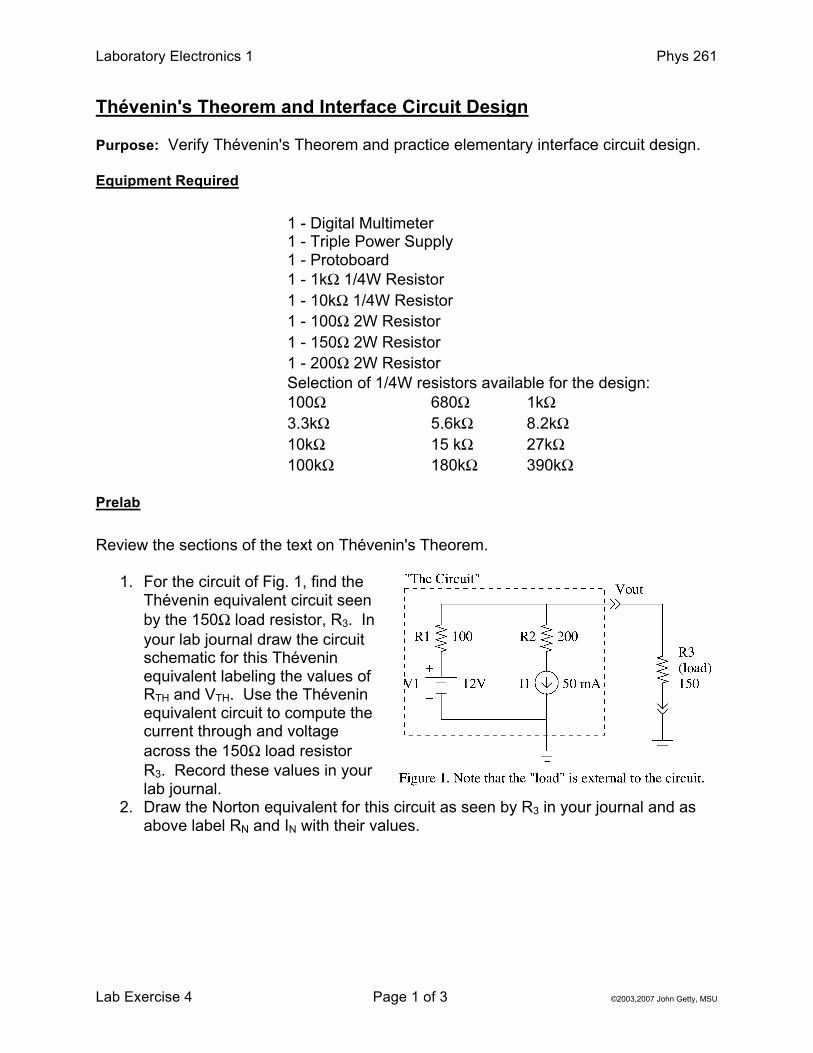
Laboratory Electronics 1 Phys 261 Lab Exercise 4 Page 1 of 3 ©2003,2007 John Getty, MSU Thévenin's Theorem and Interface Circuit Design Purpose: Verify Thévenin's Theorem and practice elementary interface circuit design. Equipment Required 1 - Digital Multimeter 1 - Triple Power Supply 1 - Protoboard 1 - 1kΩ 1/4W Resistor 1 - 10kΩ 1/4W Resistor 1 - 100Ω 2W Resistor 1 - 150Ω 2W Resistor 1 - 200Ω 2W Resistor Selection of 1/4W resistors available for the design: 100Ω 680Ω 1kΩ 3.3kΩ 5.6kΩ 8.2kΩ 10kΩ 15 kΩ 27kΩ 100kΩ 180kΩ 390kΩ Prelab Review the sections of the text on Thévenin's Theorem. 1. For the circuit of Fig. 1, find the Thévenin equivalent circuit seen by the 150Ω load resistor, R 3 . In your lab journal draw the circuit schematic for this Thévenin equivalent labeling the values of R TH and V TH . Use the Thévenin equivalent circuit to compute the current through and voltage across the 150Ω load resistor R 3 . Record these values in your lab journal. 2. Draw the Norton equivalent for this circuit as seen by R 3 in your journal and as above label R N and I N with their values.
Transcript of Thévenin's Theorem and Interface Circuit...
Laboratory Electronics 1 Phys 261
Lab Exercise 4 Page 1 of 3 ©2003,2007 John Getty, MSU
Thévenin's Theorem and Interface Circuit Design Purpose: Verify Thévenin's Theorem and practice elementary interface circuit design. Equipment Required
1 - Digital Multimeter 1 - Triple Power Supply 1 - Protoboard 1 - 1kΩ 1/4W Resistor 1 - 10kΩ 1/4W Resistor 1 - 100Ω 2W Resistor 1 - 150Ω 2W Resistor 1 - 200Ω 2W Resistor Selection of 1/4W resistors available for the design: 100Ω 680Ω 1kΩ 3.3kΩ 5.6kΩ 8.2kΩ 10kΩ 15 kΩ 27kΩ 100kΩ 180kΩ 390kΩ
Prelab Review the sections of the text on Thévenin's Theorem.
1. For the circuit of Fig. 1, find the Thévenin equivalent circuit seen by the 150Ω load resistor, R3. In your lab journal draw the circuit schematic for this Thévenin equivalent labeling the values of RTH and VTH. Use the Thévenin equivalent circuit to compute the current through and voltage across the 150Ω load resistor R3. Record these values in your lab journal.
2. Draw the Norton equivalent for this circuit as seen by R3 in your journal and as above label RN and IN with their values.
Laboratory Electronics 1 Phys 261
Lab Exercise 4 Page 2 of 3 ©2003,2007 John Getty, MSU
Procedure 1. Build the Thévenin and Norton equivalent circuits
a. Build the circuit of Figure 1. Measure and record both VOC and ISC. b. Now construct the Thévenin equivalent circuit and measure and record both
VOC and ISC.
c. Connect the 150Ω load to this circuit and measure and record VOUT.
d. Build the Norton equivalent for this circuit (now you’ll have to configure the source for a constant current equal to IN) and repeat the measurements requested in parts 1b and 1c.
2. Interface design This part of the lab will give you some experience thinking about interface circuits.
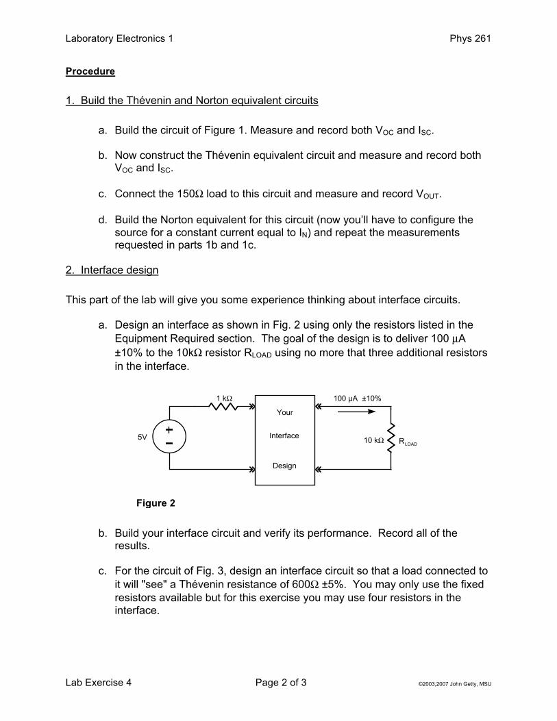
a. Design an interface as shown in Fig. 2 using only the resistors listed in the Equipment Required section. The goal of the design is to deliver 100 µA ±10% to the 10kΩ resistor RLOAD using no more that three additional resistors in the interface.
b. Build your interface circuit and verify its performance. Record all of the
results.
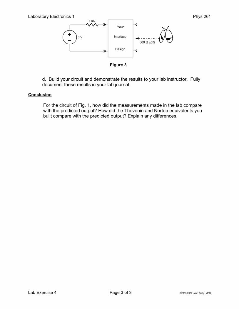
c. For the circuit of Fig. 3, design an interface circuit so that a load connected to it will "see" a Thévenin resistance of 600Ω ±5%. You may only use the fixed resistors available but for this exercise you may use four resistors in the interface.
1 kΩ
Your
Interface
Design
100 µA ±10%
10 kΩ RLOAD5V
Figure 2
Laboratory Electronics 1 Phys 261
Lab Exercise 4 Page 3 of 3 ©2003,2007 John Getty, MSU
d. Build your circuit and demonstrate the results to your lab instructor. Fully
document these results in your lab journal. Conclusion
For the circuit of Fig. 1, how did the measurements made in the lab compare with the predicted output? How did the Thévenin and Norton equivalents you built compare with the predicted output? Explain any differences.
1 kΩ
Your
Interface
Design
5 V600 Ω ±5%
Figure 3