Three-dimensional guidance for Endovascular Aortic Repair
87
Three-dimensional guidance for Endovascular Aortic Repair Giasemi Koutouzi Department of Radiology Institute of Clinical Sciences Sahlgrenska Academy at University of Gothenburg Gothenburg 2017
Transcript of Three-dimensional guidance for Endovascular Aortic Repair
Three-dimensional guidance for Endovascular Aortic Repair
Giasemi Koutouzi
Department of Radiology Institute of Clinical Sciences
Sahlgrenska Academy at University of Gothenburg
Gothenburg 2017

Three-dimensional guidance for Endovascular Aortic Repair © Giasemi Koutouzi 2017 [email protected] ISBN 978-91-629-0240-7 (Printed edition) ISBN 978-91-629-0241-4 (Electronic edition) http://hdl.handle.net/2077/52420 Printed in Gothenburg, Sweden 2017 Ineko AB

Τὰ πάντα ῥεῖ.
Everything flows.
Heraclitus (c. 535 – c. 475 BC)
To my family

i
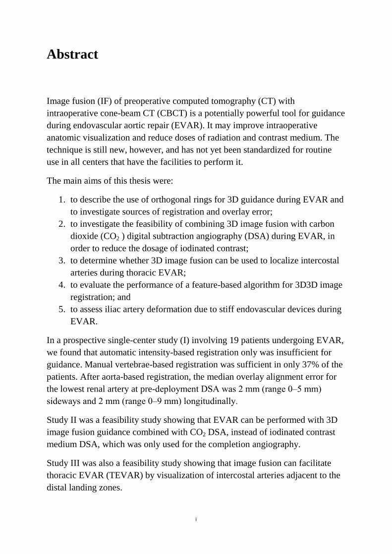
Abstract
Image fusion (IF) of preoperative computed tomography (CT) with intraoperative cone-beam CT (CBCT) is a potentially powerful tool for guidance during endovascular aortic repair (EVAR). It may improve intraoperative anatomic visualization and reduce doses of radiation and contrast medium. The technique is still new, however, and has not yet been standardized for routine use in all centers that have the facilities to perform it.
The main aims of this thesis were:
1. to describe the use of orthogonal rings for 3D guidance during EVAR and to investigate sources of registration and overlay error;
2. to investigate the feasibility of combining 3D image fusion with carbon dioxide (CO2 ) digital subtraction angiography (DSA) during EVAR, in order to reduce the dosage of iodinated contrast;
3. to determine whether 3D image fusion can be used to localize intercostal arteries during thoracic EVAR;
4. to evaluate the performance of a feature-based algorithm for 3D3D image registration; and
5. to assess iliac artery deformation due to stiff endovascular devices during EVAR.
In a prospective single-center study (I) involving 19 patients undergoing EVAR, we found that automatic intensity-based registration only was insufficient for guidance. Manual vertebrae-based registration was sufficient in only 37% of the patients. After aorta-based registration, the median overlay alignment error for the lowest renal artery at pre-deployment DSA was 2 mm (range 0‒5 mm) sideways and 2 mm (range 0‒9 mm) longitudinally.
Study II was a feasibility study showing that EVAR can be performed with 3D image fusion guidance combined with CO2 DSA, instead of iodinated contrast medium DSA, which was only used for the completion angiography.
Study III was also a feasibility study showing that image fusion can facilitate thoracic EVAR (TEVAR) by visualization of intercostal arteries adjacent to the distal landing zones.
ii
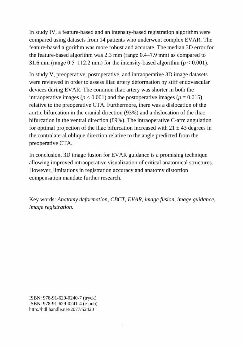
In study IV, a feature-based and an intensity-based registration algorithm were compared using datasets from 14 patients who underwent complex EVAR. The feature-based algorithm was more robust and accurate. The median 3D error for the feature-based algorithm was 2.3 mm (range 0.4‒7.9 mm) as compared to 31.6 mm (range 0.5‒112.2 mm) for the intensity-based algorithm (p < 0.001).
In study V, preoperative, postoperative, and intraoperative 3D image datasets were reviewed in order to assess iliac artery deformation by stiff endovascular devices during EVAR. The common iliac artery was shorter in both the intraoperative images (p < 0.001) and the postoperative images (p = 0.015) relative to the preoperative CTA. Furthermore, there was a dislocation of the aortic bifurcation in the cranial direction (93%) and a dislocation of the iliac bifurcation in the ventral direction (89%). The intraoperative C-arm angulation for optimal projection of the iliac bifurcation increased with 21 ± 43 degrees in the contralateral oblique direction relative to the angle predicted from the preoperative CTA.
In conclusion, 3D image fusion for EVAR guidance is a promising technique allowing improved intraoperative visualization of critical anatomical structures. However, limitations in registration accuracy and anatomy distortion compensation mandate further research.
Key words: Anatomy deformation, CBCT, EVAR, image fusion, image guidance, image registration.
ISBN: 978-91-629-0240-7 (tryck) ISBN: 978-91-629-0241-4 (e-pub) http://hdl.handle.net/2077/52420
iii
List of studies
I. Orthogonal Rings, Fiducial Markers, and Overlay Accuracy When
Image Fusion is Used for EVAR Guidance. Koutouzi G, Sandström C, Roos H, Henrikson O, Leonhardt H, Falkenberg M. Eur J Vasc Endovasc Surg. 2016 Nov;52(5):604-611. DOI: 10.1016/j.ejvs.2016.07.024.
II. EVAR Guided by 3D Image Fusion and CO2 DSA: A New Imaging Combination for Patients with Renal Insufficiency. Koutouzi G, Henrikson O, Roos H, Zachrisson K, Falkenberg M. J Endovasc Ther. 2015 Dec;22(6):912-7. DOI: 10.1177/1526602815605468.
III. 3D Image Fusion to Localise Intercostal Arteries during TEVAR. Koutouzi G, Sandström C, Skoog P, Roos H, Falkenberg M. EJVES Short Reports 2017 35, 7e10. IV. Performance of a Feature Based Algorithm for 3D-3D Registration of
CT Angiography to Cone Beam CT for Endovascular Repair of Complex Abdominal Aortic Aneurysms. Koutouzi
G, Nasihatkton
B, Danielak-Nowak M, Leonhardt H,
Falkenberg
M, Kahl F. Submitted 2017.
V. Deformation of the Iliac Artery during EVAR Koutouzi
G, Pfister
M, Breininger
K, Hellström M, Roos H, Falkenberg
M. Manuscript.
The papers have been reprinted with the permission of the publishers:
Copyright © 2016 Elsevier (Paper I) Copyright © 2015 Sage (Paper II) Copyright © 2017 Elsevier (Paper III)
iv
Table of contents
I Abstract ............................................................................................................... i
II List of studies ................................................................................................. iii
III Table of contents ........................................................................................... iv
IV Abbreviations ................................................................................................ vi
1. Introduction ..................................................................................................... 1
1.1 Aortic anatomy ............................................................................................. 1
1.2 Aortic aneurysm ........................................................................................... 2
1.3 Aortic dissection ........................................................................................... 3
1.4 Open repair ................................................................................................... 5
1.5 EVAR ........................................................................................................... 5
1.6 Preoperative imaging.................................................................................... 9
1.7 Intraoperative guidance .............................................................................. 10
2. Aims ................................................................................................................ 25
3. Patients and methods .................................................................................... 27
Ethics ................................................................................................................ 27
Patients and study design ................................................................................. 27
Image protocols and analysis ........................................................................... 31
Statistics ............................................................................................................ 34
4.Results .............................................................................................................. 39
4.1 Study I ........................................................................................................ 39
4.2 Study II ....................................................................................................... 40
4.3 Study III ...................................................................................................... 41
4.4 Study IV ..................................................................................................... 41
4.5 Study V ....................................................................................................... 43
5. Discussion ....................................................................................................... 47
5.1 3D3D registration ....................................................................................... 47
5.2 Accuracy of 2D3D overlay ........................................................................ 49
v
5.3 Vessel deformation ..................................................................................... 50
5.4 Applications of 3D image fusion ............................................................... 50
5.5 Limitations ................................................................................................. 51
6. Conclusions .................................................................................................... 53
6.1 Study I ........................................................................................................ 53
6.2 Study II ....................................................................................................... 53
6.3 Study III ...................................................................................................... 53
6.4 Study IV ..................................................................................................... 53
6.5 Study V ....................................................................................................... 54
7. Future perspectives ....................................................................................... 55
7.1 Accuracy ..................................................................................................... 55
7.2 Applications ............................................................................................... 55
8. Sammanfattning på svenska ......................................................................... 57
9. Acknowledgements ........................................................................................ 59
10. References .................................................................................................... 63
11. Studies ........................................................................................................... 76
vi
Abbreviations
3D: Three-dimensional
2D: Two-dimensional
AAA: Abdominal aortic aneurysm
AD: Aortic dissection
AP: Anteroposterior
BEVAR: Branched endovascular aortic repair
CBCT: Cone-beam computed tomography
CC: Craniocaudal
CO2: Carbon dioxide
CT: Computed tomography
CTA: Computed tomography angiography
DSA: Digital subtraction angiography
ePTFE: expanded polytetrafluoroethylene
EVAR: Endovascular aortic repair
FEVAR: Fenestrated endovascular aortic repair
FOV: Field of view
fps: frames per second
FT: Fluoroscopy time
ICC: Interclass correlation coefficient
IF: Image fusion
LAO: Left anterior oblique
MIP: Multiple intensity projections
vii
MPR: Multi-planar reconstruction
MRA: Magnetic resonance angiography
MRI: Magnetic resonance imaging
mSv: Millisievert
N: Number
OR: Open repair
OT: Operating time
PCI: Percutaneous coronary intervention
RAO: Right anterior oblique
SD: Standard deviation
SMA: Superior mesenteric artery
TAVR: Transcatheter aortic valve replacement
TIPS: Transjugular intrahepatic portosystemic shunt
VRT: Volume rendering technique

viii
1
1. Introduction
1.1 Aortic anatomy
The aorta is the largest artery of the human body and it transfers oxygenated blood from the left ventricle of the heart to the rest of the body through systemic circulation. The aortic wall has three layers: intima, media, and the outer tunica adventitia [1]. The aortic segment above the diaphragm is called the thoracic aorta and includes the ascending aorta, the aortic arch, and the descending aorta. The aortic segment below the diaphragm is called the abdominal aorta.
Branches originate from each part of the aorta. The coronary arteries arise from the ascending aorta. The aortic arch has three main branches, which are located close to each other and supply the head, neck, and upper limbs: the brachiocephalic trunk, the left common carotid artery, and the left subclavian artery. The descending aorta has many small branches: the pericardial, bronchial, mediastinal, esophageal, superior phrenic, posterior intercostal (nine pairs), and subcostal arteries. The abdominal aorta has five main branches: the coeliac artery, superior mesenteric artery (SMA), renal arteries, and inferior mesenteric artery. All of them except the inferior mesenteric artery are located within a short aortic segment. Furthermore, smaller branches arise from the abdominal aorta―including the median sacral, gonadal, inferior phrenic, and lumbar arteries (usually four pairs). Distally, the aorta bifurcates into the common iliac arteries [2].
The aortic branches communicate through a rich collateral network, often allowing occlusion of several small branches as well as the inferior mesenteric artery. Occasionally, if it is essential, even the left subclavian artery or the internal iliac arteries may be intentionally covered [3, 4].
2
1.2 Aortic aneurysm
Definition
The term aneurysm comes from the ancient Greek word “ανεύρυσμα”, which means dilatation. An aneurysm is a localized arterial dilation to more than 50% of the normal diameter of the artery [5, 6]. Aneurysms may occur in any part of the aorta. Abdominal aortic aneurysms (AAAs) are the most common.
Epidemiology
AAA occurs mostly in elderly men. According to screening studies, AAA has a prevalence of approximately 1.3% in women aged 65‒80 and 4.0‒7.7% in men of the same age [7, 8, 9, 10, 11, and 12]. Recent studies have found that the incidence of AAA is decreasing, suggesting that smoking may have contributed to this decrease [13, 14]. Known risk factors for AAA apart from age and male gender include atherosclerosis, smoking [15], hypertension, and a history of AAA in a first-degree relative [16].
Symptoms/diagnosis
Most AAAs are asymptomatic, making them difficult to detect. Some patients may, however, feel a pulsatile mass in the abdomen. The natural history of aneurysm is progressive expansion, and with increasing diameter the risk of rupture increases [17, 18]. Patients with a ruptured aneurysm present with sudden onset of abdominal or back pain. The overall mortality of aortic rupture is estimated to be about 80%, and half of the deaths occur before the patient reaches the operating room [19].
If AAA is suspected, diagnosis can be set with transabdominal ultrasound. However, ultrasound has a low sensitivity regarding rupture. Computed tomography (CT) is generally the modality of choice in acute situations as well as for detailed anatomical assessment, which is crucial for preoperative planning.
3
Treatment strategies
The decision between a conservative approach and prophylactic aneurysm repair is a balance between the risk of rupture and the risk from the operation. Furthermore, the patient’s life expectancy and personal preferences should be taken into account [20].
Results from two large, randomized studies [21, 22] have indicated that it is safe to wait for an abdominal aneurysm to reach a diameter of 5.5 cm before intervening with surgery if the patient is compliant with surveillance routines. Aortic repair should also be considered if growth of the aneurysm is rapid or if there are symptoms [23].
The threshold diameter for treatment of thoracic aortic aneurysms (TAAs) is 5.5-6 cm. Above this diameter, the risk of death, rupture, or dissection is estimated to be 15.6% per year [24, 25].
There are two options for aortic aneurysm repair: open repair (OR) and minimally invasive endovascular aortic repair (EVAR).
1.3 Aortic dissection
Definition
Aortic dissection (AD) is a life threatening condition caused by intima tear and penetration of blood into the space between the intima and media, forming a second blood-filled lumen within the aortic wall. Depending on the length of time from the onset of symptoms, AD can be divided into acute (< 2 weeks from symptoms), subacute (2‒6 weeks from symptoms), and chronic (> 6 weeks from symptoms). Furthermore, there are anatomic classifications of aortic dissection, which are important since they have a central role in decision-making regarding treatment. According to the Stanford classification, aortic dissections can be divided into type A, involving the ascending aorta (proximal to the brachiocephalic artery) regardless of the location of the intima tear, and type B, which does not involve the ascending aorta [25].
4
Epidemiology
The incidence of AD is estimated to be 2.6–3.5 cases per 100,000 person-years [26, 27, 28] and approximately two-thirds are type A and one-third are type B [29]. Risk factors include hypertension [30], connective tissue disorders such as Marfan syndrome in young patients [31, 32], and bicuspid aortic valve [25].
Symptoms/diagnosis
Most of the patients with AD present with abrupt onset of pain located in the chest, in the back, or in the abdomen―but this symptom is non-specific. Depending on the arteries involved in the dissection, the patients may also have other symptoms. Syncope or stroke are often seen when the carotid arteries are involved. Cardiac tamponade by blood pericardial effusion and acute aortic insufficiency may be present in type A dissections. Symptoms from renal, mesenteric, or limb ischemia may be present when the respective arteries are involved [33, 34, 35]. The preferred imaging modality for diagnosis is computed tomography angiography (CTA) and transesophageal echocardiography for type A dissections and CTA for type B dissections [36]. Magnetic resonance angiography (MRA) is the modality of choice for surveillance, especially in young patients [37, 38].
Treatment strategies
Open surgical repair is the treatment of choice for type A dissections. Medical treatment is indicated for uncomplicated type B dissections, whereas surgical or endovascular repair is appropriate for descending aorta dissections that are complicated by rupture, malperfusion, ongoing pain, or hypotension [39, 40].
5
1.4 Open repair
The traditional treatment for AAA is OR. OR is also the treatment of choice for type A aortic dissections. In 1951, Dubost performed the first OR with replacement of an aortic aneurysm with a homograft [41]. Synthetic vascular grafts were introduced in the 1950s [42, 43]. In 1966, Creech described the surgical technique of endoaneurysmorraphy with intraluminal graft replacement [44]. OR is performed under general anesthesia. The abdominal aorta lying in the retroperitoneal space is exposed through a large incision. Vascular clamps are then placed proximal and distal to the aneurysm. The aneurysm is opened and excluded with an inlay prosthetic straight or bifurcated graft made of knitted or woven Dacron sealed with collagen or gelatin, or of expanded polytetrafluoroethylene (ePTFE) [45, 46].
OR has good long-term durability, but perioperative morbidity and mortality remain high, with perioperative complications such as spinal cord, cerebral, and visceral ischemia [47, 48, 49].
1.5 EVAR
EVAR and thoracic EVAR (TEVAR) were pioneered by Volodos, Parodi, and Dake in the 1990s [50, 51, 52, 53]. Since then, there has been increasing interest in endovascular treatment of aortic aneurysm and aortic dissection.
With EVAR, laparotomy and aortic cross-clamping are avoided, the blood loss is less compared to OR, and the hospital stay is typically shorter for the patient. EVAR can be performed under general anesthesia but even under local or regional anesthesia, occasionally allowing aneurysm repair for patients who are not eligible for OR [54].
Large randomized controlled trials of treatment for AAAs showed a significantly lower 30-day mortality with EVAR compared to OR (1.7% as
6
opposed to 4.7%). However, the long-term mortality results are controversial. There have been studies showing similar mortality rates for the two methods, while in a 15-year follow-up of the randomized EVAR 1 study, OR appeared to have reduced mortality rates compared to EVAR. [55, 56, 57, 58, 59]. According to the Swedish National Registry for Vascular Surgery, EVAR accounted for 60% of infrarenal AAA procedures in 2016.
For standard infrarenal EVAR, a “proximal neck” of healthy aorta of at least 10‒15 mm between the renal arteries and the aneurysm is required. A modular stent graft system is placed within the aorta in order to exclude the aneurysm and prevent aneurysm growth and rupture [50, 51, 60, 61, 62]. A stent graft consists of a fabric tube (often polyester or ePTFE) and an expanding metal stent framework (of stainless steel or nitinol). The procedure is performed via small access holes in the common femoral arteries. The stent graft is then advanced into the aorta using catheters and guide wires under fluoroscopic image guidance. The proximal seal zone for an infrarenal aneurysm is just below the lowest renal artery and the distal seal zones are in the common iliac arteries just above the internal iliac arteries. A possible disadvantage of EVAR is the risk of incomplete aneurysm sealing, resulting in persistent blood flow in the aneurysm sac, either because the graft does not seal completely at the proximal or distal attachment zones (type I endoleak) or between the modular components, or due to blood flow through holes in the endograft (type III endoleak). Endoleak may also appear due to retrograde filling of the aneurysm from other small aortic branches (type II endoleak). Furthermore, a disadvantage of endovascular repair is the use of radiation and contrast medium during the procedure.
There is a continuous rapid evolution of endografts, which are available in a variety of sizes with durable materials and improved delivery systems, allowing not only the treatment of infrarenal aneurysms but also thoracic and complex aortic aneurysms that engage the aortic branches.
TEVAR
TEVAR involves aortic repair with a stent graft in the thoracic aorta. Indications are thoracic aneurysms in the descending aorta, complicated acute type B
7
dissection, progressive dilatation of chronic type B dissection, symptomatic penetrating aortic ulcer, and traumatic transection [39, 63].
The proximal landing zone is often close to the aortic arch. Occasionally, the left subclavian artery is intentionally covered by the stent graft in order to achieve an adequate seal. The distal landing zone is above the celiac trunk. However, the decision about treatment length of the descending aorta should take into consideration the risk of spinal cord ischemia, which is increased with coverage of longer aortic segments [64]. Postoperative paraplegia is one of the most serious complications after repair of the descending and thoraco-abdominal aorta.
The blood supply to the distal spinal cord is mainly via the anterior and posterior radicular branches of the intercostal and lumbar arteries. There is also a collateral network with branches arising from subclavian and internal iliac arteries. Often, one of the radicular arteries is dominant and is called the artery of Adamkiewiezc, or arteria radicularis magna, and it is thought to be the major artery supplying the anterior spinal artery of the spinal cord. This artery tends to arise between the ninth thoracic vertebra and the second lumbar vertebra in most people (85%) [65, 66].
Fenestrated/branched EVAR
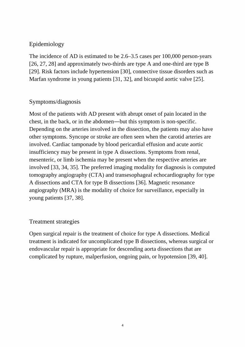
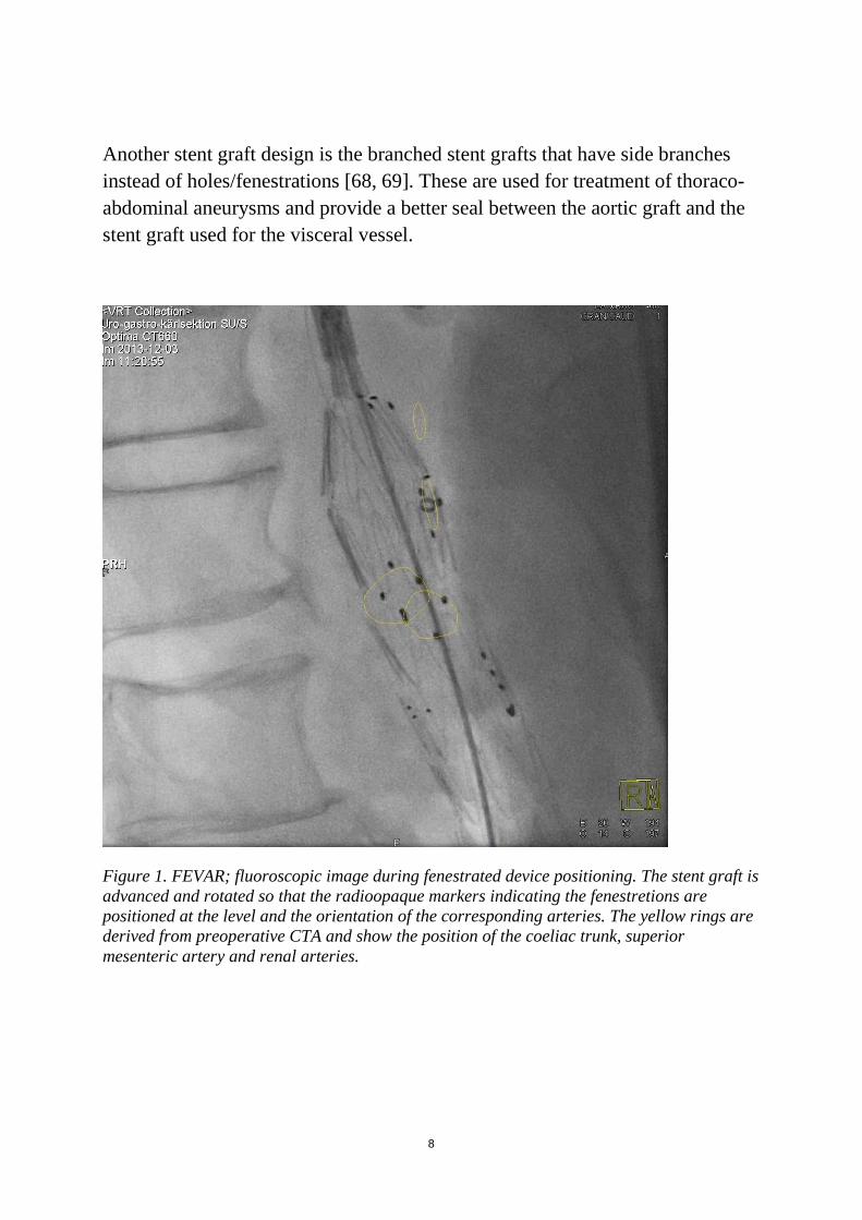
Complex aortic aneurysms with short proximal aortic neck or engagement of the visceral and renal arteries can now also be treated with minimally invasive technique (fenestrated and branched EVAR―FEVAR and BEVAR). FEVAR was first described in 1996 [67]. Fenestrated stent grafts have openings (fenestrations) in the fabric that allow perfusion of the visceral vessels. The fenestrations are in the proximal part of the stent graft at the height and orientation of the target vessels. FEVAR is a challenging and time-consuming procedure. The stent graft should be accurately positioned to match the position of the aortic branches without covering them, and should enable vessel catheterization through the fenestrations (Figure 1).
8
Another stent graft design is the branched stent grafts that have side branches instead of holes/fenestrations [68, 69]. These are used for treatment of thoraco-abdominal aneurysms and provide a better seal between the aortic graft and the stent graft used for the visceral vessel.
Figure 1. FEVAR; fluoroscopic image during fenestrated device positioning. The stent graft is advanced and rotated so that the radioopaque markers indicating the fenestretions are positioned at the level and the orientation of the corresponding arteries. The yellow rings are derived from preoperative CTA and show the position of the coeliac trunk, superior mesenteric artery and renal arteries.
9
1.6 Preoperative imaging
Pre-procedural planning has a central role in the success of EVAR. Imaging is essential for assessment of the extent and morphology of an aneurysm, and in deciding the feasibility of EVAR.
Computed tomography angiography
CTA is a fast, non-invasive, widely available and reproducible modality that can provide all necessary anatomical information for operation planning.
CTA is the modality of choice for a detailed assessment of the aortic anatomy and pathology prior to aortic repair, unless there is a contraindication such as renal insufficiency. In such cases, reasonable alternatives are magnetic resonance imaging (MRI), CT without contrast medium combined with additional CO2 DSA, or CTA with low kilovoltage and minimal administration of contrast medium.
Ideally, images should be acquired in arterial phase and reconstructed with thin slices―preferably < 1 mm. The whole thoracic and abdominal aorta should be included in the images, as 12% of patients with an AAA will have a multilevel aortic disease [70].
The morphology of proximal and distal landing zones and also the dimensions of access vessels should be carefully assessed. The relation to adjacent aortic branches should be taken into account. Furthermore, preoperative CTA is used to predict optimal C-arm angulations for visualization of the anatomy during the actual procedure. Measurements are usually performed using 3D visualization software allowing calculation of center lumen of flow.
The disadvantages of CTA include the radiation and nephrotoxic contrast agents.
10
Magnetic Resonance Angiography
MRA can also be used in the preoperative assessment. MRA is obtained without radiation or iodinated contrast medium. Other benefits are the ability to differentiate the aortic wall from the aortic lumen and to assess arterial wall movement and quantify blood flow. However, MRA requires a longer time for image acquisition and the image quality may be impaired by artifacts. MRA gives less information about aortic calcifications than CT. The cost of MR is higher that of CT, and it is contraindicated for patients with implantations such as pacemakers. Furthermore, MRI usually has lower spatial resolution than CT and is less accessible [71].
1.7 Intraoperative guidance
Fluoroscopy and Digital Subtraction Angiography (DSA)
Although EVAR planning is performed using 3D preoperative CT images, the actual procedure is usually performed with two-dimensional (2D) fluoroscopic and digital subtraction angiography (DSA) guidance.
During fluoroscopy, multiple images are acquired, resulting in a movie-like dataset of consecutive images. Fluoroscopy facilitates guidance during endovascular procedures when advancing and manipulating catheters, guide wires, and devices. However, for assessment and visualization of vessel anatomy, the use of contrast is needed. The most common form of angiography during EVAR is DSA.
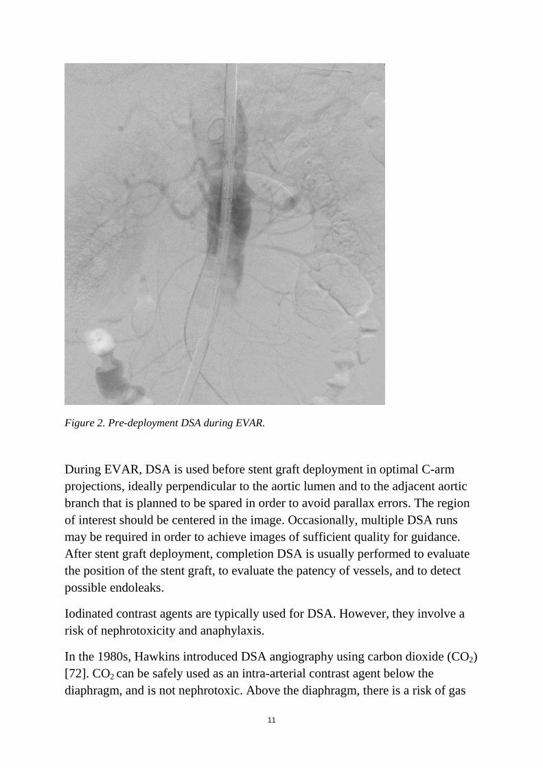
During DSA, the surrounding tissues and vessel wall are subtracted from images acquired after introduction of contrast; thus, only the lumen of the vessel is visible (Figure 2). Contrast, brightness, and sharpness can be adjusted. Roadmaps derived from DSA can also be displayed on the real-time fluoroscopic screen for guidance. However, the images are two-dimensional and therefore valid only for the exact C-arm angulation and table position of that specific acquisition. Furthermore, patient movement may impair the image quality.
11
Figure 2. Pre-deployment DSA during EVAR.
During EVAR, DSA is used before stent graft deployment in optimal C-arm projections, ideally perpendicular to the aortic lumen and to the adjacent aortic branch that is planned to be spared in order to avoid parallax errors. The region of interest should be centered in the image. Occasionally, multiple DSA runs may be required in order to achieve images of sufficient quality for guidance. After stent graft deployment, completion DSA is usually performed to evaluate the position of the stent graft, to evaluate the patency of vessels, and to detect possible endoleaks.
Iodinated contrast agents are typically used for DSA. However, they involve a risk of nephrotoxicity and anaphylaxis.
In the 1980s, Hawkins introduced DSA angiography using carbon dioxide (CO2) [72]. CO2 can be safely used as an intra-arterial contrast agent below the diaphragm, and is not nephrotoxic. Above the diaphragm, there is a risk of gas
12
embolism in the spinal, coronary, and cerebral arteries [73]. However, the image quality may be inferior to that with iodinated contrast DSA due to gas buoyancy, bolus fragmentation, and poorer vessel demarcation.
CBCT
Intraoperative cone-beam computed tomography (CBCT) is an imaging technique that uses data acquired with a flat-panel detector C-arm angiography system to generate intraoperative CT-like images. Modern angiography suites are now often equipped with such advanced imaging systems.
To obtain the projection data, the C-arm performs a sweep around the patient, acquiring up to several hundred images, depending on the scan protocol selected. The sweep usually covers a range of 200 degrees (180 degrees plus detector fan angle) so that a projection of the object can be acquired from all angles in order to reconstruct the object in three dimensions. First used in neuroradiology [74, 75], CBCT is now also used in interventional radiology and vascular surgery, often to align preoperative data to the C-arm or to check and document actual stent graft deployment at the end of the procedure.
The commercially available CBCT systems are DynaCT (Siemens Medical Solutions, Forcheim, Germany), XperCT (Philips Medical Systems, Eindhoven, the Netherlands), and Innova CT (GE Healthcare, Waukesha, WI, USA).
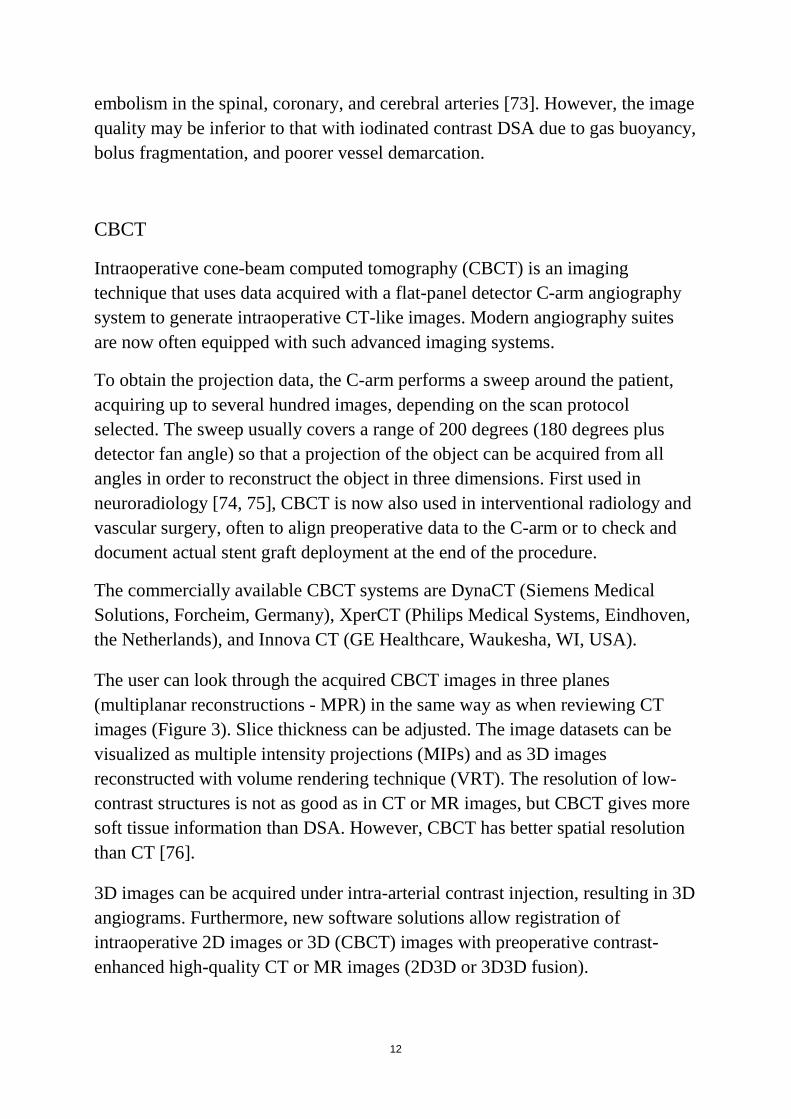
The user can look through the acquired CBCT images in three planes (multiplanar reconstructions - MPR) in the same way as when reviewing CT images (Figure 3). Slice thickness can be adjusted. The image datasets can be visualized as multiple intensity projections (MIPs) and as 3D images reconstructed with volume rendering technique (VRT). The resolution of low-contrast structures is not as good as in CT or MR images, but CBCT gives more soft tissue information than DSA. However, CBCT has better spatial resolution than CT [76].
3D images can be acquired under intra-arterial contrast injection, resulting in 3D angiograms. Furthermore, new software solutions allow registration of intraoperative 2D images or 3D (CBCT) images with preoperative contrast-enhanced high-quality CT or MR images (2D3D or 3D3D fusion).
13
Image acquisition for CBCT has a duration of 4‒20 seconds, depending on the protocol and system used.
Figure 3. Unenhanced intraoperative CBCT at the level of the abdominal aorta. MPR and VRT images.
Contrast-enhanced CBCT
CBCT with intra-arterial contrast results in a 3D angiogram. 3D angiograms during EVAR can be used for intraoperative guidance before stent graft deployment, or as completion angiograms to confirm aneurysm sac exclusion, or for immediate detection of endoleaks [77]. CBCT with or without contrast can also be used during EVAR to detect kinks or stent graft compression [78].
The patient should be positioned so that the region of interest is at the center of rotation of the system (iso-center). The image delay may vary depending on the
14
size of the vessel to be depicted and the proximity of the catheter to the region of interest. For aorta and iliac arteries, the optimal imaging delay is approximately 2‒3 sec.
Compared to DSA, findings and locations from CBCT are easier to correlate with information from previous CT or MRI scans. Furthermore, vascular structures can be more accurately assessed in relation to complex overlapping anatomy [79].
Dual-volume CBCT is another alternative for visualization of arterial anatomy. A first acquisition may serve as a mask and a second acquisition as a 3D angiography, thus allowing reconstruction of subtracted images in 3D. This can be helpful for assessment of complex anatomy adjacent to radiopaque material such as coils, and also for detection of bleeding and endoleaks. Dual-volume CBCT can also be useful for assessment of contrast enhancement patterns in oncological interventions [76].
Image fusion
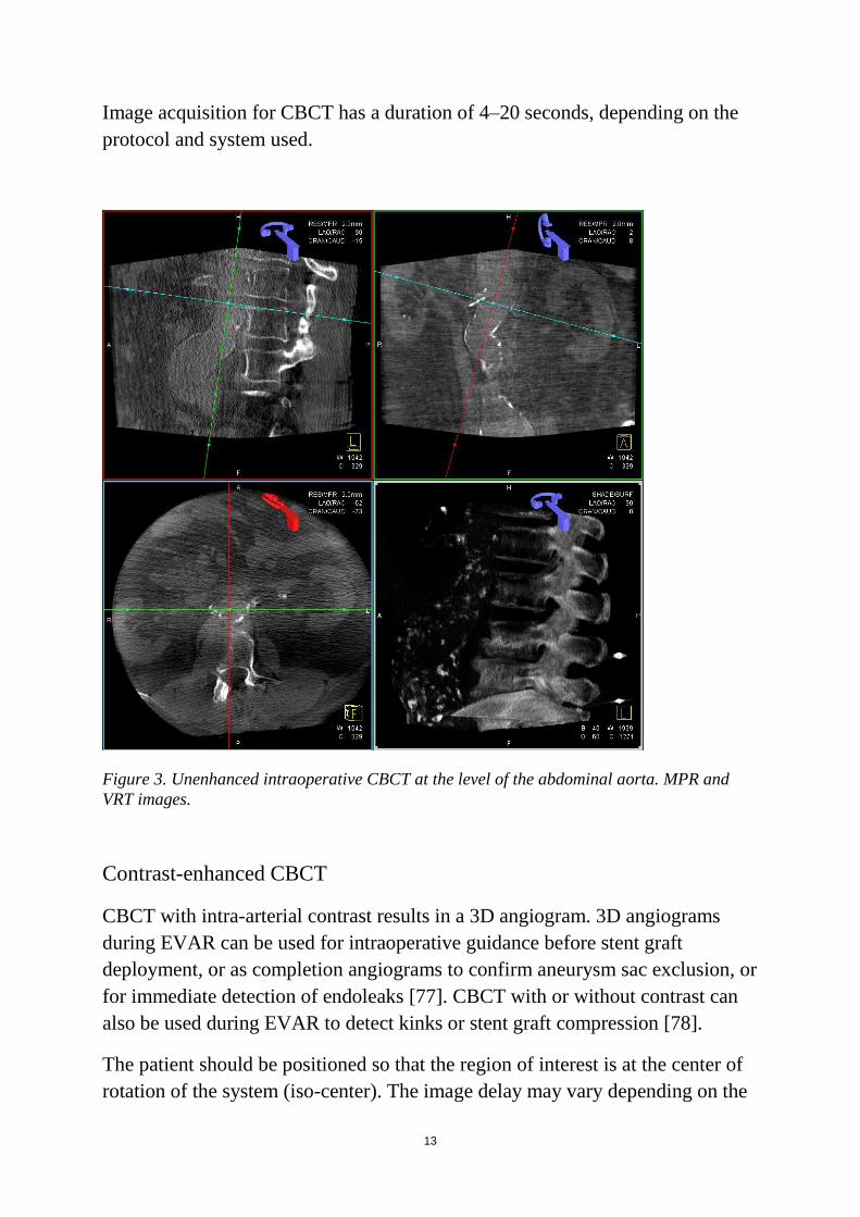
IF is a technique that allows overlay of two or more datasets together on one screen. In interventional radiology, this technique is used to project anatomical 3D information derived from preoperative CTA or MRA on the live fluoroscopic image [80, 81].
The typical workflow is as follows (Figure 4):
Figure 4. Image fusion workflow for EVAR.
15
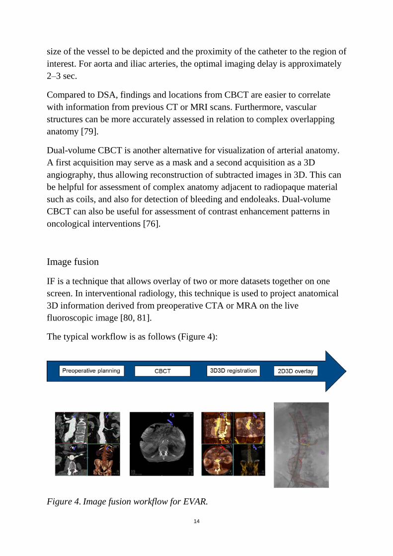
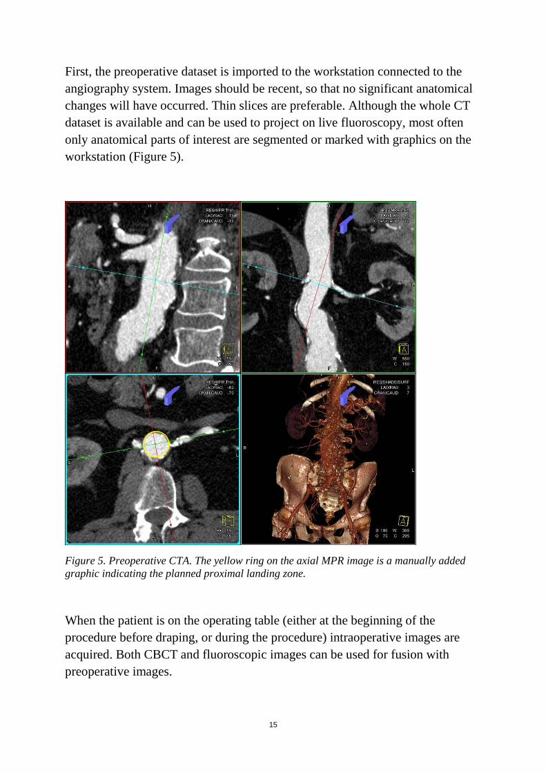
First, the preoperative dataset is imported to the workstation connected to the angiography system. Images should be recent, so that no significant anatomical changes will have occurred. Thin slices are preferable. Although the whole CT dataset is available and can be used to project on live fluoroscopy, most often only anatomical parts of interest are segmented or marked with graphics on the workstation (Figure 5).
Figure 5. Preoperative CTA. The yellow ring on the axial MPR image is a manually added graphic indicating the planned proximal landing zone.
When the patient is on the operating table (either at the beginning of the procedure before draping, or during the procedure) intraoperative images are acquired. Both CBCT and fluoroscopic images can be used for fusion with preoperative images.
16
The next step is registration of intraoperative images to preoperative images. Images during the operation facilitate recognition of the exact position of the patient in relation to the angiography system. After image registration, the anatomy from the two datasets is aligned and transformed to one coordinate system.
All the information included in the preoperative dataset is available for projection on the live fluoroscopic screen. Using dedicated software, information from preoperative planning can be overlaid on the live fluoroscopic monitor for guidance. The overlay can be made to adapt automatically to changes in C-arm angulation, table position, and zoom―but current technology does not yet allow correction for patient motion and anatomic changes in the patient.
The 3D information is available during the whole procedure. However, since several different factors may affect the accuracy of the overlaid information, there is still a need to have intraoperative feedback on anatomy and to adjust the overlaid information before relying on it.
3D3D image registration
3D3D registration means alignment of two different 3D datasets, translating them into the same coordinate system [82]. Image registration may be rigid or deformable, and can be achieved by matching features or intensity.
For EVAR, there is usually an intraoperative CBCT superimposed on a preoperative CT so that the anatomy and the pathology in the area of interest match. The intraoperative CBCT is usually performed without contrast at the start of the procedure, before vascular access. The images are automatically transferred to the post-processing workstation. Registration can be performed either manually by aligning MPR projections, or by using automatic algorithms, or semi-automatically.
Fully manual registration is often time-consuming and requires thorough anatomical and procedural insight. The vertebral column is clearly depicted in both datasets, and it is an appealing anatomical region for manual alignment. However, since the area of interest for EVAR is the aorta, the alignment should be rather focused on the aorta itself, checking for alignment of aortic outline and calcifications. Bone alignment may serve as a rough initial superimposition.
17
Automatic registration algorithms in commercially available systems are often intensity-based using normalized mutual information as similarity measure. These algorithms calculate the statistical dependence between the image intensities of corresponding voxels in both images, which is assumed to be maximal if the images are geometrically aligned. Time can be saved when automatic registration has sufficient results. However, fully automatic registration faces several difficulties. The field of view (FOV) of a CTA is often much larger than that of a CBCT. The exact posture of the patient may also differ between the preoperative and intraoperative image acquisitions. The aorta is enhanced by contrast in CTA whereas the CBCT images are not enhanced. Finally, the slice thickness of the available preoperative CTA is not always optimal.
The performance of currently available algorithms for automatic 3D3D registration is not fully satisfactory, and there is often a need for time-consuming manual adjustments, which are difficult to perform from the operating table.
2D3D image registration
Image registration can also be facilitated by 2D fluoroscopic images rather than by intraoperative CBCT. For registration in three planes, two 2D images perpendicular to each other can be registered to the preoperative examination.
The 2D3D approach may be more convenient, since it requires less time and almost no radiation compared to the 3D3D approach. However, when using 2D3D fusion the registration is usually focused on bones only and not on the aorta. Furthermore, the registration―although seemingly easier―requires alignment of two datasets from completely different modalities (typically alignment of a 3D volume-rendered reconstruction from preoperative CT to a fluoroscopic image), which may also be a challenging task.
Advantages with image fusion
The concept of intraoperative image fusion with preoperative diagnostic 3D images is a potentially powerful guiding tool to help operators during endovascular procedures. Image fusion may boost the confidence of the
18
operating physicians during the procedure, but such benefits are difficult to evaluate.
Several authors have, however, reported their early clinical experience with fused imaging during EVAR, suggesting that the method is feasible and can reduce both the radiation and the contrast medium doses.
Reduction of Radiation exposure
Patients undergoing EVAR are exposed to a considerable amount of radiation from preoperative imaging, from the procedure, and from postoperative surveillance. Additional radiation may also be accumulated when there is reoperation.
The medical staff is also exposed to radiation, since they perform several procedures each year.
In a prospective study, Sailer et al. (2014) evaluated the radiation exposure of abdominal CBCT [83]. The estimated average effective dose for abdominal CBCT in that study was 4.3 mSv (range 1.1‒7.4 mSv). This corresponds to half of the radiation of an abdominal multi-detector CT (8 mSv, range 3.5‒25 mSv) and to approximately 7 minutes of fluoroscopy time in the same region. The medical staff are often in a protected area during CBCT acquisition, but the patient is exposed.
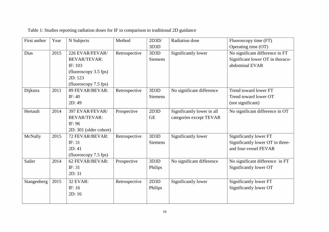
However, using image fusion may reduce total radiation dose and/or fluoroscopy/operating time for EVAR. From 2011 to the present, six studies have compared radiation doses, fluoroscopy time, and operating time using image fusion or fluoroscopic guidance (Table 1) [83, 84, 85, 86, 87, 88]. Three studies reported on FEVAR/BEVAR, one study on standard EVAR, and two studies on both complex and standard EVAR. Four studies included patients where 3D3D registration was used and two studies included patients where 2D3D registration was used. Both prospective and retrospective studies have been performed. The retrospective studies have the advantage of having no bias for actively trying to reduce dose in the fusion group.
19
Table 1: Studies reporting radiation doses for IF in comparison to traditional 2D guidance
First author Year N Subjects Method 2D3D/ 3D3D
Radiation dose
Fluoroscopy time (FT) Operating time (OT)
Dias 2015 226 EVAR/FEVAR/ BEVAR/TEVAR: IF: 103 (fluoroscopy 3.5 fps) 2D: 123 (fluoroscopy 7.5 fps)
Retrospective 3D3D Siemens
Significantly lower
No significant difference in FT Significant lower OT in thoraco-abdominal EVAR
Dijkstra 2011 89 FEVAR/BEVAR: IF: 40 2D: 49
Retrospective 3D3D Siemens
No significant difference Trend toward lower FT Trend toward lower OT (not significant)
Hertault 2014 397 EVAR/FEVAR/ BEVAR/TEVAR: IF: 96 2D: 301 (older cohort)
Prospective 2D3D GE
Significantly lower in all categories except TEVAR
No significant difference in OT
McNally 2015 72 FEVAR/BEVAR: IF: 31 2D: 41 (fluoroscopy 7.5 fps)
Retrospective 3D3D Siemens
Significantly lower Significantly lower FT Significantly lower OT in three- and four-vessel FEVAR
Sailer 2014 62 FEVAR/BEVAR: IF: 31 2D: 31
Prospective 3D3D Philips
No significant difference No significant difference in FT Significantly lower OT
Stangenberg 2015 32 EVAR: IF: 16 2D: 16
Retrospective 2D3D Philips
Significantly lower Significantly lower FT Significantly lower OT
20
Reduction of Contrast medium dose
EVAR involves an increased risk of development of renal complications, mostly related to administration of contrast agents (contrast-induced nephropathy, CIN) but also due to removal of embolic debris during manipulation of endovascular devices [90, 91, 92]. CIN is more frequent in patients with pre-existing renal insufficiency, and contrast should therefore be used with caution in this patient group especially.
Recent studies have suggested that image fusion may reduce the use of iodinated contrast. In 2011, Kobeiter et al. reported the first zero-contrast TEVAR using 3D3D registration for image fusion [93]. In 2015, Kaladji et al. reported on 6 cases (5 standard EVAR and 1 TEVAR) using no contrast in the preoperative CT nor during the procedure [94]. To check the accuracy of the overlay, the vessels that were planned to be spared were catheterized instead. Ultrasound was used for endoleak detection. A recent paper from Ahmad et al. (2016) described a complex FEVAR and iliac-branched case using no iodinated contrast, but carbon dioxide instead [95].
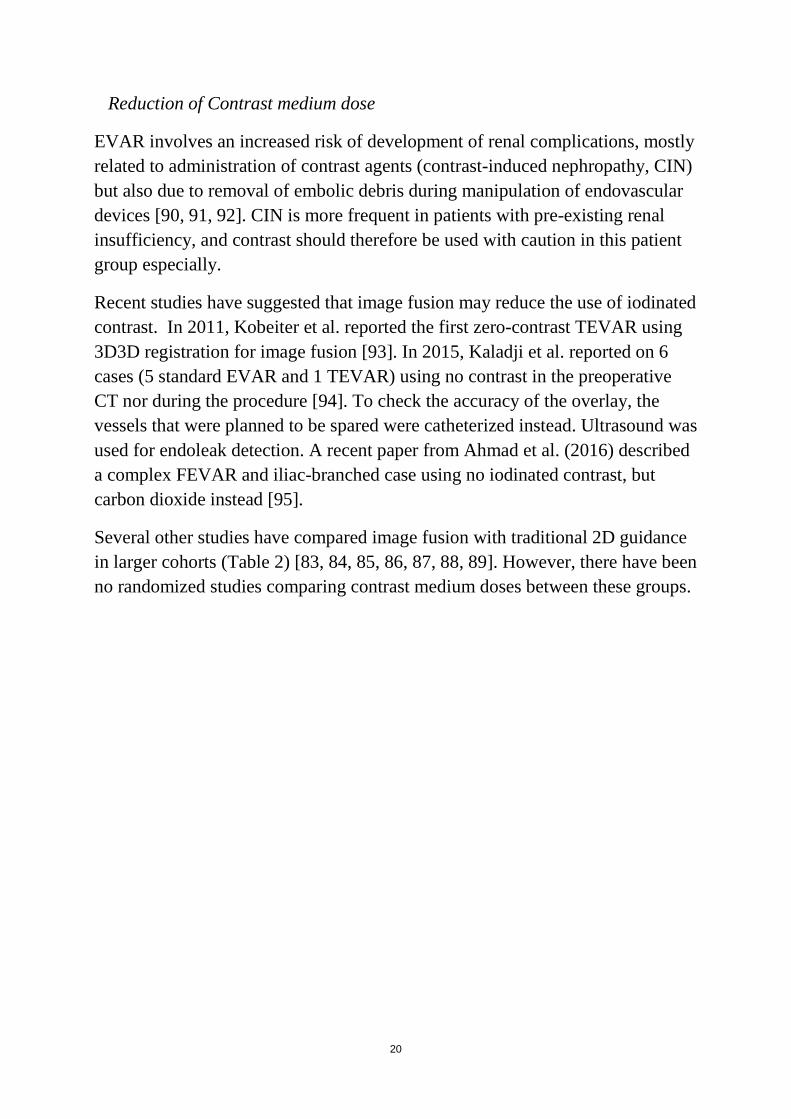
Several other studies have compared image fusion with traditional 2D guidance in larger cohorts (Table 2) [83, 84, 85, 86, 87, 88, 89]. However, there have been no randomized studies comparing contrast medium doses between these groups.
21
Table 2: Studies reporting contrast medium doses for IF in comparison to 2D guidance
First author Year Subjects Method 2D3D/3D3D Contrast Volume
Dias 2015 226 EVAR/ FEVAR/ BEVAR/TEVAR: IF: 103 2D: 123
Retrospective 3D3D Siemens
Significantly lower
Dijkstra 2011 89 FEVAR/BEVAR: IF: 40 2D: 49
Retrospective 3D3D Siemens
Significantly lower
Hertault 2014 397 EVAR/FEVAR/ BEVAR/TEVAR: IF: 96 2D: 301 (older cohort)
Prospective 2D3D GE
Significantly lower in FEVAR/BEVAR
McNally 2015 72 FEVAR/BEVAR: IF: 31 2D: 41
Retrospective 3D3D Siemens
Significantly lower
Sailer 2014 62 FEVAR/BEVAR: IF: 31 2D: 31
Prospective 3D3D Philips Significantly lower
Strangenberg 2015 32 EVAR: IF: 16 2D: 16
Retrospective 2D3D Philips
Significantly lower
Tacher 2013 23 Complex EVAR: IF: 14 2D: 9
Retrospective 3D3D Philips
Significantly lower
22
Limitations with image fusion
Although the above data suggest that image fusion may reduce two important parameters (radiation and contrast dose), this technique is still novel and is not yet standardized for routine use in all centers that have the facilities to perform it. There are several limitations that may explain this.
Time
Medical staff may feel that using image fusion is time-consuming.
Preoperative image preparation may be time-consuming, but does not necessarily have to be performed on the same day as the procedure; it can be done in advance instead. Image acquisition itself and image reconstruction are relatively fast with modern fluoroscopic systems and take only a few seconds.
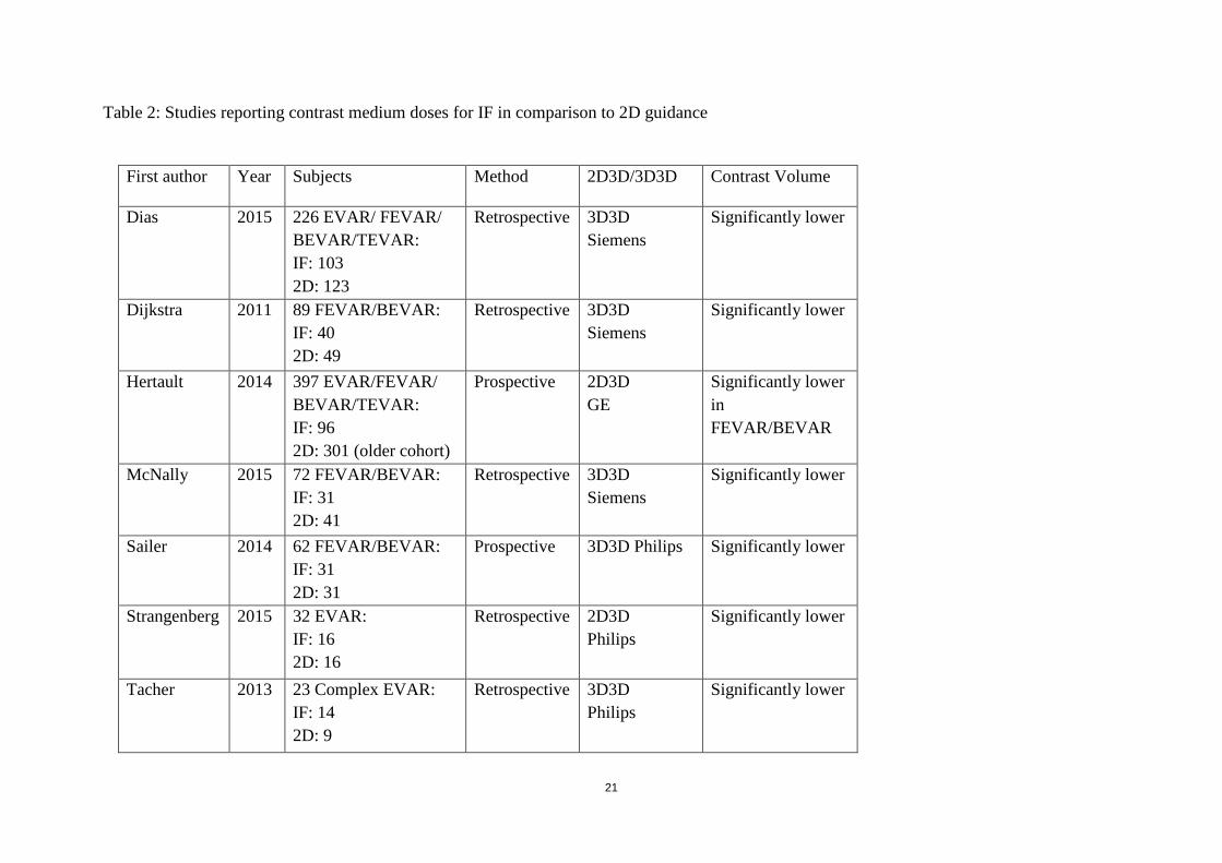
There are, however, several other tasks that may take time: positioning of the patient on the operating table so that the C-arm can sweep without collision, draping of the patient to maintain sterility during image acquisition (Figure 6), selection of an appropriate protocol, and positioning of the area of interest in the field of view prior to image acquisition. Image registration can be the most cumbersome task if the automatic tools do not work, since it is time-consuming and requires interaction with advanced software.
Figure 6. Image from the hybrid operating room of Sahlgrenska University hospital. Patient draping allowing CBCT aquisition while preserving sterility.
23
The total time taken for these tasks will of course depend on how familiar the team is with the equipment, and the frequency of use of image fusion. This additional time may overshadow the possible reduction in duration of the procedure and the reduction in total radiation dose, and may limit the use of this valuable technology.
Accuracy
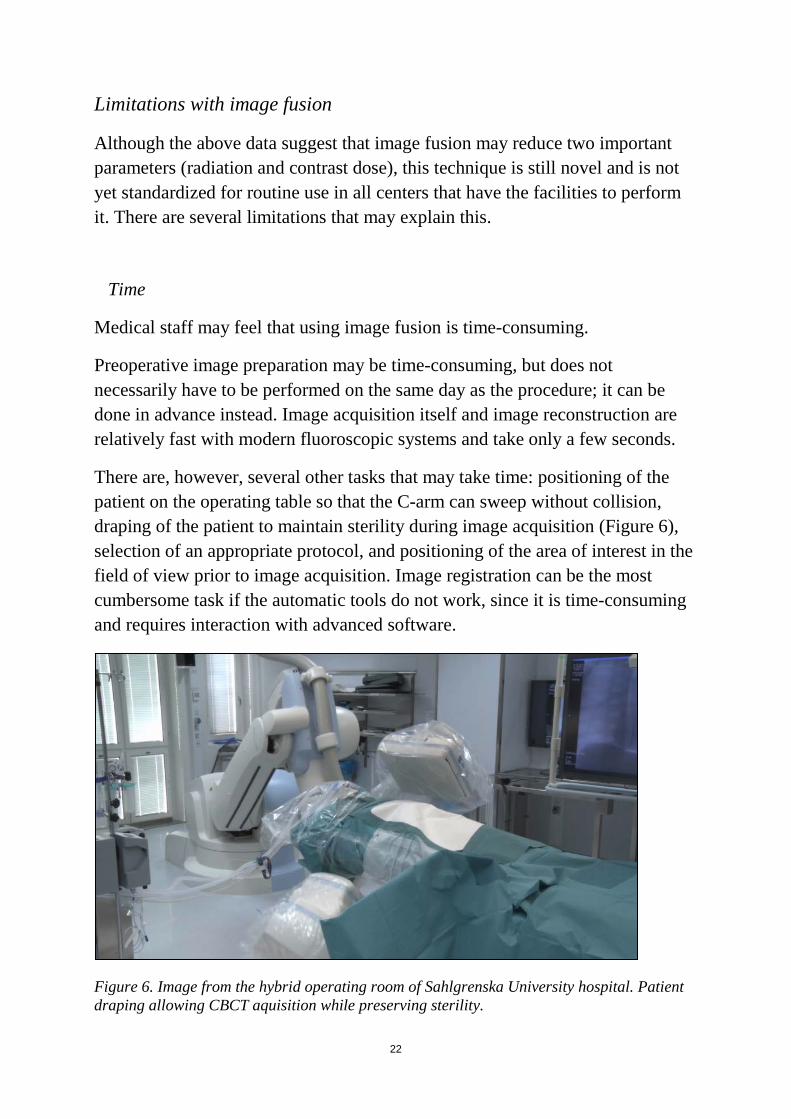
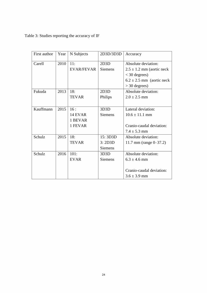
Another factor that influences the use of image fusion is the accuracy of the method. Information projected on a live fluoroscopic screen is derived from the preoperative dataset which was performed at a different time point, on a different table, and with the patient in a somewhat different position―all of which may affect the precision of the overlaid image (Figure 7). In addition, the accuracy may be adversely affected by anatomy distortion from endovascular devices and patient movements, including breathing. Tortuous vessels may straighten upon insertion of stiff endovascular guide wires. At certain points, vessels may be relatively fixed by connective tissue, whereas in other parts the vessels may be more mobile. Recent studies have described experience with image fusion, showing that the method is not sufficiently accurate to be solely relied upon (Table 3) [96, 97, 98, 99, 100]. At present there have been no reports from randomized studies comparing the accuracy of 2D3D fusion with the accuracy of 3D3D fusion.
Figure 7. Pre-deployment DSA. Suboptimal accuracy of 2D3D overlay.
24
Table 3: Studies reporting the accuracy of IF
First author Year N Subjects 2D3D/3D3D Accuracy
Carell
2010 11: EVAR/FEVAR
2D3D Siemens
Absolute deviation: 2.5 ± 1.2 mm (aortic neck < 30 degrees) 6.2 ± 2.5 mm (aortic neck > 30 degrees)
Fukuda 2013 18: TEVAR
2D3D Philips
Absolute deviation: 2.0 ± 2.5 mm
Kauffmann 2015 16 : 14 EVAR 1 BEVAR 1 FEVAR
3D3D Siemens
Lateral deviation: 10.6 ± 11.1 mm Cranio-caudal deviation: 7.4 ± 5.3 mm
Schulz 2015 18: TEVAR
15: 3D3D 3: 2D3D Siemens
Absolute deviation: 11.7 mm (range 0‒37.2)
Schulz 2016 101: EVAR
3D3D Siemens
Absolute deviation: 6.3 ± 4.6 mm Cranio-caudal deviation: 3.6 ± 3.9 mm
25
2. Aims Overall aim:
To improve the use of CBCT and image fusion for EVAR guidance and to investigate sources of error.
Specific aims:
1. To describe the use of orthogonal rings for 3D guidance during EVAR and to investigate sources of registration and overlay error;
2. To investigate the feasibility of combining 3D fusion with CO2 DSA during EVAR in order to reduce the dose of iodinated contrast;
3. To investigate the use of 3D image fusion in order to localize and preserve intercostal arteries during TEVAR;
4. To compare the accuracy of a feature-based algorithm for 3D3D image registration of preoperative CTA with intraoperative CBCT with that of a traditional intensity-based algorithm;
5. To assess iliac artery deformation due to stiff endovascular devices during EVAR.

26

27
3. Patients and methods
3.1 Ethics
This thesis involved patients treated with EVAR with 3D guidance in the hybrid room of Sahlgrenska University Hospital during the period 2012‒2017. All the invasive procedures evaluated in this project are established routines at Sahlgrenska University Hospital and the imaging techniques and equipment used during the procedures (hardware and software) have CE marking for clinical use. To ensure compliance with good research practice, two ethical applications were submitted and they were approved by the regional ethical board (entry nos. 132-14 and 593-16).
3.2 Patients and study design
Study I
This was a prospective single-center study describing the use of 3D image fusion for intraoperative guidance during EVAR. Nineteen patients who underwent EVAR at Sahlgrenska University Hospital during 2014-2015 were included. Renal arteries and targeted stent graft positions were marked manually with 3D graphics/rings orthogonal to the respective center lines in the preoperative CT. A CBCT without contrast was acquired at the start of the procedure. Radiopaque reference objects (ECG electrodes) (Figure 8) attached to the back of the patient were used as fiducial markers in order to detect patient movement intraoperatively.
Figure 8. ECG-electrodes used as fiducial markers.
28
The accuracy of automatic (intensity-based) 3D3D registration and vertebrae-based registration in aligning the lowest renal artery ostium was evaluated. Finally, the accuracy of 2D3D overlay after aortic wall-based 3D3D registration was quantified, using fluoroscopy and DSA as ground truth.
Study II
This was a feasibility study presenting a new combination of imaging techniques that may help to reduce the use of iodinated contrast during EVAR. We presented our initial experience from three patients with pre-existing renal insufficiency who were undergoing EVAR. Relevant anatomical structures were marked in the preoperative CT. A 3D3D image registration between the preoperative CT and an intraoperative CBCT was performed in order to overlay anatomical information on live fluoroscopy. Verification of the correct overlay position (or adjustment if necessary) was based on CO2 DSA instead of iodine DSA. The stent grafts were positioned and deployed based on the information overlaid.
Study III
This was a feasibility study presenting the use of 3D image fusion for intraoperative localization of intercostal arteries during TEVAR, in order to minimize the risk of postoperative paraparesis.
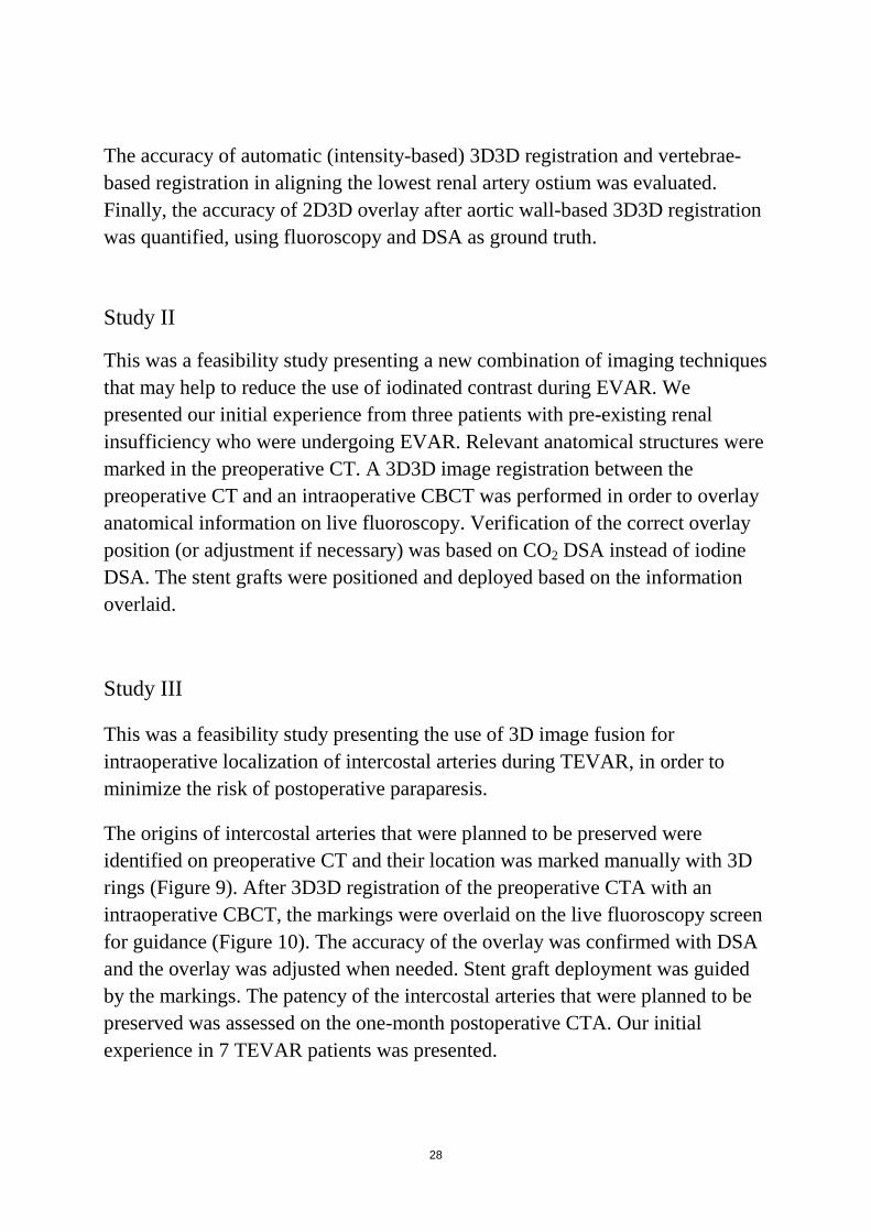
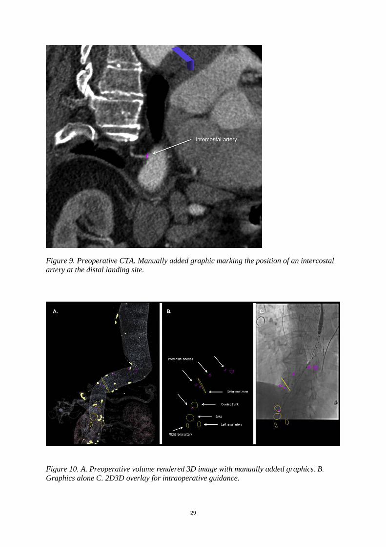
The origins of intercostal arteries that were planned to be preserved were identified on preoperative CT and their location was marked manually with 3D rings (Figure 9). After 3D3D registration of the preoperative CTA with an intraoperative CBCT, the markings were overlaid on the live fluoroscopy screen for guidance (Figure 10). The accuracy of the overlay was confirmed with DSA and the overlay was adjusted when needed. Stent graft deployment was guided by the markings. The patency of the intercostal arteries that were planned to be preserved was assessed on the one-month postoperative CTA. Our initial experience in 7 TEVAR patients was presented.
29
Figure 9. Preoperative CTA. Manually added graphic marking the position of an intercostal artery at the distal landing site.
Figure 10. A. Preoperative volume rendered 3D image with manually added graphics. B. Graphics alone C. 2D3D overlay for intraoperative guidance.

30
Study IV This was a retrospective study with off-line validation (not during the procedure, but afterwards) of a new feature-based algorithm for automatic 3D3D registration and comparison of its accuracy with that of a commercially available intensity-based algorithm. The new algorithm was evaluated using CT-CBCT datasets from 14 patients with complex abdominal aortic aneurysms that were treated with fenestrated or branched EVAR in the hybrid operating room of Sahlgrenska University Hospital between 2012 and 2015. Automatic 3D3D registration of a pre-procedural CTA with an intra-procedural unenhanced CBCT was performed after the procedures. Positions (3D coordinates) of six predetermined anatomical landmarks (three aortic calcifications and three distinct points in the nearby vertebrae) were identified in both datasets independently by two radiologists and the distances between each set of coordinates (for each landmark) were calculated. The same evaluations were performed using the intensity-based algorithm, and the results were compared.
Study V
In this study, we reviewed and analyzed both intraoperative contrast-enhanced CBCT images and pre- and postoperative CT images from 17 patients who underwent EVAR at Sahlgrenska University Hospital during the period 2013‒2017. CBCT was contrast-enhanced and was acquired after deployment of the main body trunk and insertion of a stiff guide wire through the contralateral stump (Figure 11). The CBCT images were used to guide subsequent deployment of the iliac limbs bilaterally. The CBCT images were retrospectively compared with the pre- and postoperative CT images to assess iliac artery deformation by the stiff devices and whether anatomy deformation affects optimal C-arm angulations to project iliac bifurcations.

31
Figure 11. Contrast-enhanced CBCT with stiff devices in both iliac arteries.
3.3 Image protocols and analysis
Preoperative CTA
All patients who were included in studies I‒V had a preoperative CT performed within 8 months of the EVAR procedure. Throughout the studies, a variety of 64-slice multi-detector spiral CT scanners from different manufacturers were used for the preoperative CTs at Sahlgrenska University Hospital and the referral hospitals of the region. All CT scans were acquired in arterial phase―except for one patient in study II, who had a preoperative CT without contrast due to renal insufficiency. Routine protocols designed for aortic imaging were used. The tube voltage varied between 80 and 120 kV. The contrast medium used was of non-ionic low-osmolar type at a concentration of 350 mg/mL iodine and an injection rate of 4‒5 mL/s. The available datasets at
32
the time of the procedures had a slice thickness varying between 0.7 and 3.0 mm.
For case planning (studies I, II, and III), the images were imported in the 3D visualization and processing application (syngo InSpace; Siemens Healthcare GmbH). For patients included in studies I and II, rings were manually drawn around the origins of the renal arteries and one larger ring was drawn around the aorta, orthogonal to its center line, at the optimal cranial extension of the aortic stent graft. For patients in study III, the ostia of intercostal arteries in the aortic segment of the planned distal attachment and also the ostia of the coeliac trunk, the superior mesenteric artery, and the renal arteries were marked with rings. Furthermore a large circumferential ring marked the aortic lumen, orthogonal to its center line at the targeted distal landing site.
CBCT
All CBCTs were performed intraoperatively with the patients under general anesthesia in the hybrid operating room of Sahlgrenska University Hospital.
This hybrid operating room is equipped with a flat-panel detector C-arm angiography system (Artis zeego; Siemens Healthcare GmbH). The sweep is configured to go from 84° LAO to 113° RAO, in which a series of 248 frames over 5 seconds at intervals of 0.8 degrees are acquired around an axis perpendicular to the detector plane.
The size of the detector is 30 cm × 40 cm and it can be orientated both in landscape mode and in portrait mode. The resulting projection images are transferred automatically to a dedicated workstation (syngo X Workplace with syngo DynaCT reconstruction software; Siemens Healthcare GmbH) connected to the angiography system and reconstructed to a volume of isotropic voxel size. For landscape orientation, the reconstructed volume has 372 axial slices with a voxel size of 0.5 mm, resulting in a cylinder of diameter 25.6 cm and a height in craniocaudal direction of 18.6 cm. For portrait orientation, 305 axial slices with a voxel size of 0.78 mm are obtained, resulting in a cylinder 20.0 cm in diameter and 23.7 cm high.
For studies I‒IV, intraoperative CBCT studies were performed without contrast and for study V, intraoperative CBCT was contrast-enhanced.
33
Studies I‒IV The patients were centered on the table so that the anatomical area of interest was included in the field of view, to provide the best conditions for the 3D fusion process that followed. For studies I and II, the patients were centered on the table so that the spine was visible in the middle of a frontal view and the iliac spines at the caudal end. In the lateral view, the lumbar vertebrae were visible in the lower aspect of the image. For patients included in study IV, the field of view was positioned slightly cranially in order to depict the aortic segment that includes the coeliac trunk and superior mesenteric artery. In study III, the patients were centered so that the spine was slightly on the right side of the field of view in a frontal view and both the distal landing site of the descending aorta and the diaphragm were included in the images. For patients included in study I, fiducial markers (ECG-electrodes) were attached to the back of the patient close to the anatomical area of treatment, between Th12 and L4. The fiducials were included in CBCT and their position was marked manually with rings in the post-processing workstation. Study V In study V, CBCTs were performed focusing on the iliac arteries, after deployment of the main stent graft trunk and after insertion of a stiff guide wire into the contralateral gate, and before deployment of iliac stent graft limbs. At this time point, there was blood flow to both iliac arteries through the contralateral gate of the main trunk. During image acquisition, diluted iodine contrast agent (Omnipaque, 100 mg/mL iodine) was injected into the aortic aneurysm with an injection rate of 7 ml/s, resulting in a total contrast volume of 42 ml and a total iodine dose of 4.2 g.
34
Accuracy of 3D3D Registration
Automatic rigid intensity-based registration:
For all patients in studies I‒IV, an intensity-based normalized mutual information algorithm was used for automatic image registration (syngo InSpace 3D-3D Fusion; Siemens Healthcare GmbH). The alignment of the aortic wall and visceral ostia was visually checked on MPR fused images and whenever unsatisfactory manual adjustments or completely manual re-registration was performed.
The accuracy of the 3D registration based on the above algorithm was evaluated in studies I and IV using the post-processing workstation (syngo X Workplace).
In study I, acceptable accuracy was defined as < 3 mm 3D alignment error of the lowest renal artery ostium.
In study IV, the accuracy of the intensity-based algorithm was quantified by measuring the 3D registration error between six predefined landmarks (vascular calcifications and bony structures) on CTA and the corresponding landmarks on CBCT. For estimation of inter-observer agreement, the landmarks were identified in CBCT by two independent radiologists who were blinded as to each other’s landmarks and regarding the results of the registrations.
Automatic feature-based registration
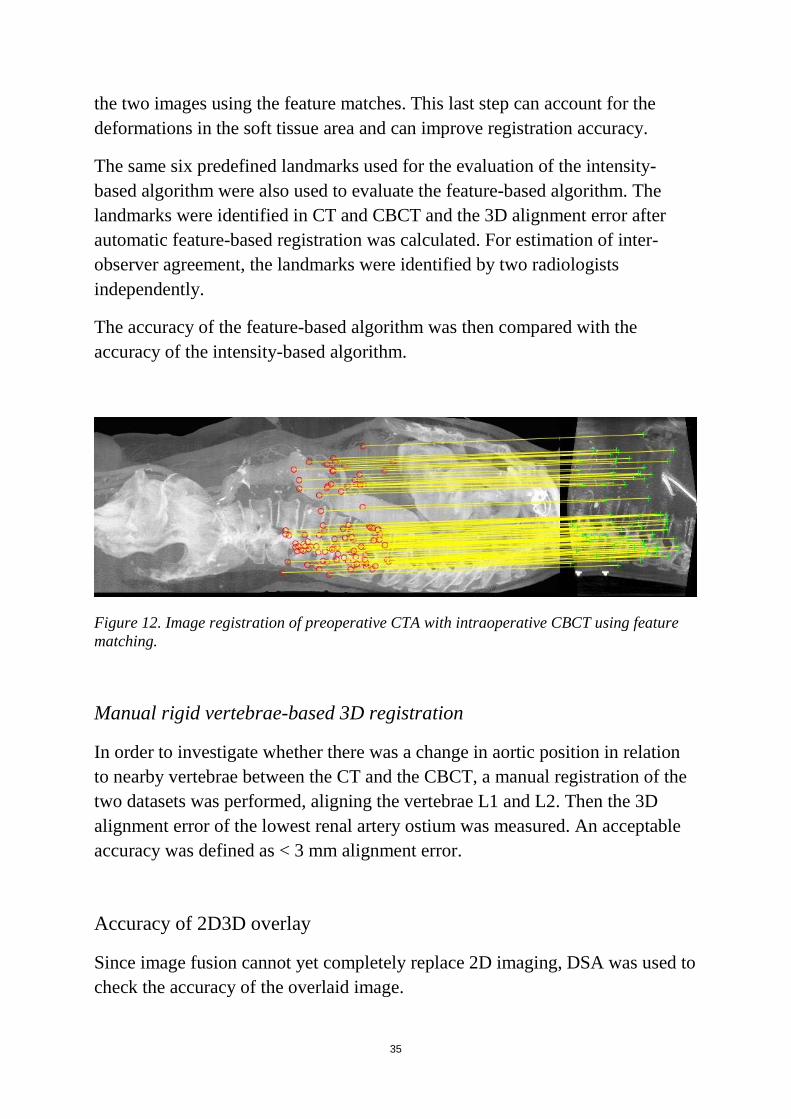
A new automatic feature-based algorithm was evaluated in study IV. This algorithm is based on matching 3D features such as points, edges, and contours detected in both CT and CBCT images (Figure 12). First, an affine transformation of the datasets is performed. Such transformations do not necessarily preserve angles between lines or distances between points, but parallel lines remain parallel and the ratio between the distances of the features is preserved. Then, taking into account the initial affine estimate, the algorithm removes all points that do not belong to the transformed CBCT volume and repeats the feature-matching procedure locally in a 1-cm radius of its transformed location in the other image. In a final step, the algorithm computes a thin-plate spline transformation, which is a non-linear deformation, between
35
the two images using the feature matches. This last step can account for the deformations in the soft tissue area and can improve registration accuracy.
The same six predefined landmarks used for the evaluation of the intensity-based algorithm were also used to evaluate the feature-based algorithm. The landmarks were identified in CT and CBCT and the 3D alignment error after automatic feature-based registration was calculated. For estimation of inter-observer agreement, the landmarks were identified by two radiologists independently.
The accuracy of the feature-based algorithm was then compared with the accuracy of the intensity-based algorithm.
Figure 12. Image registration of preoperative CTA with intraoperative CBCT using feature matching.
Manual rigid vertebrae-based 3D registration
In order to investigate whether there was a change in aortic position in relation to nearby vertebrae between the CT and the CBCT, a manual registration of the two datasets was performed, aligning the vertebrae L1 and L2. Then the 3D alignment error of the lowest renal artery ostium was measured. An acceptable accuracy was defined as < 3 mm alignment error.
Accuracy of 2D3D overlay
Since image fusion cannot yet completely replace 2D imaging, DSA was used to check the accuracy of the overlaid image.
36
For studies I and III, iodinated contrast was used as contrast agent and CO2 was used instead in study II.
The accuracy of the overlaid image during interventions was evaluated in study I. We measured the sideways and cranio-caudal misalignment error of the fiducial markers as seen on fluoroscopy and the corresponding CBCT-derived rings. This was performed in order to evaluate intraoperative patient motion, which might affect the accuracy of image registration.
Furthermore, after DSA the sideways and cranio-caudal alignment error of the lowest renal artery between DSA and the corresponding CT-derived ring was measured.
Postoperative CT
Studies III and V also included a review of postoperative CTAs. In study III, the postoperative images were reviewed to check the patency of the intercostal arteries that were planned to be preserved. In study V, the postoperative CTAs were reviewed to assess common iliac artery length and tortuosity index after EVAR.
Iliac artery deformation
In study V, iliac artery anatomy was compared between preoperative CTA, intraoperative contrast-enhanced CBCT, and first follow-up CTA. Comparisons included common iliac artery lengths along the center lumen line and common iliac artery tortuosity index (defined as common iliac artery length along the center lumen line divided by the 3D distance between aortic and iliac bifurcation). Optimal angulations for visualization of the iliac bifurcation were computed. The location of the aortic and the iliac bifurcation was compared between the preoperative CTA and the CBCT. The anatomic assessment was performed using a syngo InSpace prototype workstation.
37
3.4 Statistics No formal sample size calculations were performed, due to the exploratory design of the studies. Statistical calculations were performed with SPSS 24 (IBM Corp., Armonk, NY, USA). Study I
Descriptive statistics were used in this study. Relative frequencies were used to express the percentage of successful 3D3D registration, and median with range was used to present accuracy data (due to the small sample size).
Studies II and III
Absolute values have been reported, since these papers described our experience from a small number of cases.
Study IV
Continuous data are presented as median with range (for data that were not normally distributed) and as mean with standard deviation (for normally distributed data). The Wilcoxon signed rank test was used for comparison of accuracy between the feature-based algorithm and the intensity-based algorithm and for comparison of accuracy between aortic and bony landmarks for each algorithm. Interclass correlation coefficient (ICC) (2,1) was used to assess inter-rater reliability. Furthermore, Spearman’s rank correlation coefficient was used to investigate whether the slice thickness of the preoperative CT influenced the registration accuracy.
Study V
Data have been presented as mean and standard deviation (for normally distributed data) or median and range (for data that were not normally distributed). The distribution of data was checked with the Kolmogorov-Smirnov test. The paired-samples t-test was used to compare common iliac artery length between preoperative and intraoperative data and also between preoperative and postoperative data. The paired-samples t-test was also used to

38
compare optimal C-arm projections between preoperative and intraoperative data. Wilcoxon’s signed rank test was used to compare common iliac tortuosity index between preoperative and intraoperative data and also between preoperative and postoperative data. Any p-value of less than 0.05 was considered to be statistically significant.
39
4. Results
4.1 Study I
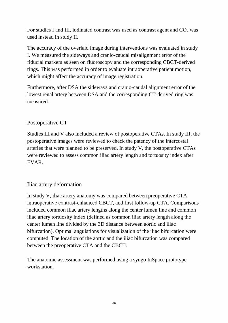
Orthogonal rings readily facilitated visualization of anatomical positions and guided optimal C-arm projections without obscuring the fluoroscopic field of view. Fiducial makers helped in detecting misalignment caused by patient movement during the procedures. Automatic intensity-based registration alone was insufficient for EVAR guidance. Manual registration based on vertebrae L1 and L2 was sufficient in only 7 of 19 patients (37%). Using the final adjusted registration as overlay, the median alignment error for the lower renal artery at pre-deployment DSA was 2 mm (range 0‒5 mm) sideways and 2 mm (range 0‒9 mm) longitudinally, and was predominantly in the cranial direction (Figure 13).
Figure 13. Diagram showing the measured misalignment of the lower renal artery in pre-deployment DSA and the corresponding 3D ring (centre of diagram) after 2D3D overlay.
40
4.2 Study II
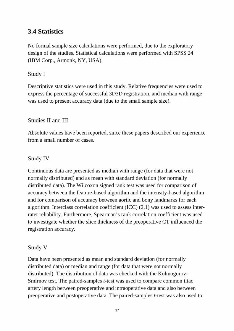
Three EVAR procedures in patients with renal insufficiency were presented. 3D image fusion in combination with CO2 DSA was feasible and helpful for guidance during EVAR (Figure 14). All procedures were performed successfully using 2.2 g (patient 1), 4.8 g (patient 2), and 4 g (patient 3) iodinated contrast for the completion angiography.
Figure 14. (A) VR image from preoperative CTA of a 75-year-old man with juxtarenal abdominal aortic aneurysm; 3D graphics idetify the renal arteries, the superior mesenteric artery (SMA), and the proximal landing zone just below the SMA ostium. (B) 2D3D overlay: graphics from the CTA are overlaid on the fluoroscopy screen for intraoperative guidance. (C) Ring-guided catheterization of the right renal artery. CO2 DSA with opacification of the aorta and the right renal artery confirms the correct position of the catheter. (D) Parallel stent-grafts to both renal arteries and the main bifurcated stent-graft are placed immediately below the SMA.
41
4.3 Study III 3D image fusion guidance was feasible, and technical success was achieved in all cases. In total, 15 intercostal arteries in the vicinity of the distal landing zone were planned to be preserved, and all appeared to be patent at postoperative CTA. 4.4 Study IV
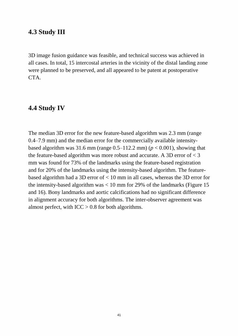
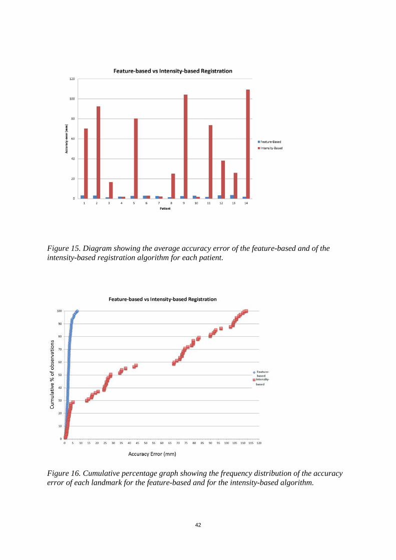
The median 3D error for the new feature-based algorithm was 2.3 mm (range 0.4‒7.9 mm) and the median error for the commercially available intensity-based algorithm was 31.6 mm (range 0.5‒112.2 mm) (p < 0.001), showing that the feature-based algorithm was more robust and accurate. A 3D error of < 3 mm was found for 73% of the landmarks using the feature-based registration and for 20% of the landmarks using the intensity-based algorithm. The feature-based algorithm had a 3D error of < 10 mm in all cases, whereas the 3D error for the intensity-based algorithm was < 10 mm for 29% of the landmarks (Figure 15 and 16). Bony landmarks and aortic calcifications had no significant difference in alignment accuracy for both algorithms. The inter-observer agreement was almost perfect, with ICC > 0.8 for both algorithms.
42
Figure 15. Diagram showing the average accuracy error of the feature-based and of the intensity-based registration algorithm for each patient.
Figure 16. Cumulative percentage graph showing the frequency distribution of the accuracy error of each landmark for the feature-based and for the intensity-based algorithm.
43
4.5 Study V
Iliac artery length
There was a significant decrease in length of the common iliac artery from the preoperative CT to the intraoperative CBCT, with a mean decrease of 5.6 mm (SD = 5.8 and 95% CI from 3.5 to 7.7 mm). There was also a significant decrease in length of the common iliac artery from the preoperative CT to the postoperative CT, with a mean decrease of 3.2 mm (SD = 7.0 with 95% CI from 0.7 to 5.8 mm).
Common iliac artery tortuosity index
There was a significant reduction in the common iliac artery tortuosity index in intraoperative CBCT relative to preoperative CTA. However, we found no significant difference in the tortuosity index of the common iliac artery between preoperative and postoperative CTA.
Position of aortic bifurcation
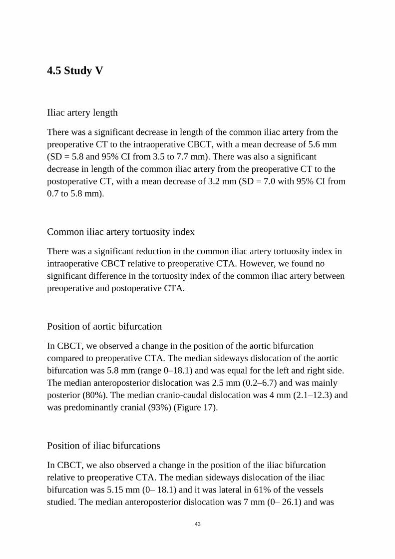
In CBCT, we observed a change in the position of the aortic bifurcation compared to preoperative CTA. The median sideways dislocation of the aortic bifurcation was 5.8 mm (range 0‒18.1) and was equal for the left and right side. The median anteroposterior dislocation was 2.5 mm (0.2‒6.7) and was mainly posterior (80%). The median cranio-caudal dislocation was 4 mm (2.1‒12.3) and was predominantly cranial (93%) (Figure 17).
Position of iliac bifurcations
In CBCT, we also observed a change in the position of the iliac bifurcation relative to preoperative CTA. The median sideways dislocation of the iliac bifurcation was 5.15 mm (0‒ 18.1) and it was lateral in 61% of the vessels studied. The median anteroposterior dislocation was 7 mm (0‒ 26.1) and was
44
mostly anterior (89%). The median cranio-caudal dislocation was 5.8 mm (0.5‒ 15.5) and was mostly cranial (66%) (Figure 17).
Figure 17. Scatter plots showing the displacement of aortic and iliac bifurcations.
Optimal angulations
The optimal angulation for projection of iliac bifurcation predicted from preoperative CTA and intraoperative CBCT differed. There was a significant increase in the anterior oblique angulation needed during the procedure for optimal projection of iliac bifurcation, with a mean increase towards the contralateral side of 21.0 degrees (SD = 43.0 and 95% CI from 5.4 to 36.5) (Figure 18).
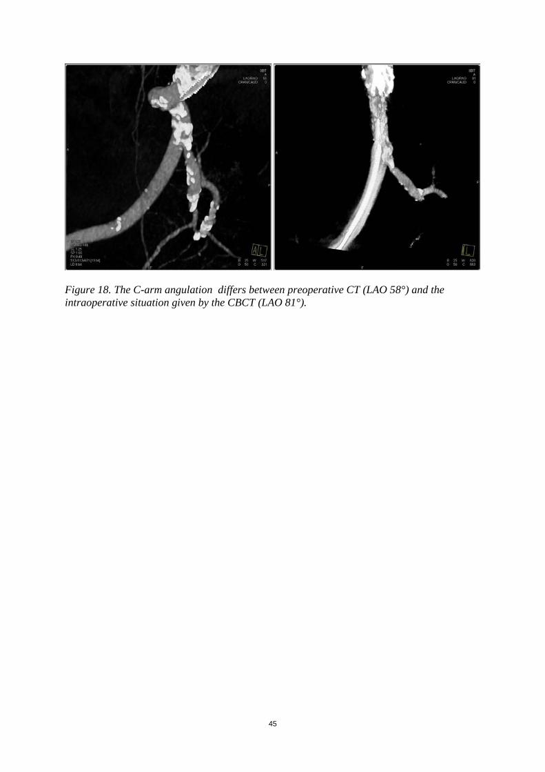
45
Figure 18. The C-arm angulation differs between preoperative CT (LAO 58°) and the intraoperative situation given by the CBCT (LAO 81°).

46
47
5. Discussion
Several aspects of three-dimensional guidance for EVAR have been addressed in the present thesis.
Different sources of error in image fusion were investigated in study I, including errors initiated during the 3D3D registration process and errors due to patient movement. Furthermore, the accuracy of 2D3D overlay was assessed. Studies II and III highlighted the role of image fusion in two different patient categories: patients undergoing EVAR who are at risk of further renal insufficiency and patients undergoing TEVAR who are at risk of spinal cord ischemia. In study IV, we evaluated a new automatic algorithm for 3D3D registration that may reduce errors and simplify the registration process. Finally, in study V we assessed iliac artery deformation by stiff endovascular devices, which affects the accuracy of 2D3D overlay.
5.1 3D3D registration
Automatic registration
The performance of automatic registration using a standard commercially available rigid, intensity-based algorithm proved to be insufficient when used in 19 clinical cases in study I. There is a clear need for better automatic tools.
Image registration is a key step in image fusion. Automatic tools for image registration are particularly helpful when they are accurate. Automatic registration of CT to CBCT is, however, a challenging task due to different sources of movement and due to the differences in the characteristics of the modalities. Rigid registration presumes that the spatial relationship between anatomical structures in the patient is constant. However, in reality, breathing movements, different positioning of the patient, and different timing of respective image acquisition are factors that may affect the anatomy. Furthermore, differences between modalities―such as different size of scanned area, different resolution, and presence or absence of contrast in one of the
48
modalities―make the task of registration even more challenging, especially for algorithms that are based on matching of voxel intensities.
To the best of our knowledge, there are only few publications evaluating 3D3D image fusion of CT to CBCT in clinical cases, and all refer to intensity-based algorithms [99, 101]. In study IV, we evaluated a feature-based algorithm for registration of CTA to CBCT and found that it was more accurate and robust than a standard intensity-based algorithm. The 3D error for the feature-based algorithm was found to be < 3 mm in 73% of the landmarks, and the error was <10 mm for all landmarks. No extreme registration errors were found and the error measured probably reflects an even smaller error on 2D3D overlay, since only two dimensions are involved in each projection. The fact that the feature-based algorithm was not rigid makes it possible to compensate for minor differences in inner anatomy.
Since none of the algorithms is as yet accurate enough to be completely relied upon, it is important that systems that integrate them are user-friendly and allow easy human interaction for adjustments when needed.
Bone registration
Another important finding of study I was that fusing part of a patient’s anatomy does not guarantee that other parts will also be successfully registered. Bony structures of the spine are easy to use as landmarks for image registration, since they are clearly visible in both modalities. However, we showed that registration of vertebrae L1-L2, which although this lies very close to the aortic part involving visceral ostia, results in sufficient (< 3 mm) registration of the lowest renal artery ostium in just 37% of patients. This error may be caused by different positioning of the patient during the two acquisitions. For example, during CTA the patient’s legs are usually slightly bent whereas during EVAR, the patient generally lies on the operating table with the legs straight. Different phases of respiration may also contribute to this error.
This finding is of importance because bony structures serve as reference points for image registration in a 2D3D image fusion approach, since they are visible both in fluoroscopy and in CT. 2D3D registration may be less time-consuming and involves less radiation, since no CBCT is necessary. Even so, we should bear in mind that when registration is based on bony structures only, we might
49
initiate an error already in the registration phase. Errors may then be magnified with longer distances from the registration points. Compromising of accuracy may eventually translate into extra contrast medium and radiation doses. There have still been no studies comparing the accuracy and effect of 2D3D and 3D3D approaches for image registration on contrast and radiation dose.
5.2 Accuracy of 2D3D overlay
A limitation of image fusion as currently used in clinical practice is the assumption of preserved and stable anatomy during the procedures. In study I, we assessed the accuracy of 2D3D overlay. We showed that errors are partially due to change in patient position during the procedure, but greater error is caused by other factors―such as the insertion of stiff devices in the vessels.
Our results are in line with results in other publications [98, 102]. There is a pattern in error direction. In most of the cases, the visceral ostia are displaced cranially at the time of pre-deployment DSA. In practice, this means that if stent graft positioning was to rely completely on the fused image, the stent would most probably not cover the ostia but there would be a risk of inadequate sealing.
For detection of patient movement, we found it very helpful to use fiducial markers attached to the skin of the patient. What is necessary is that structures used as reference points are radiopaque and visible both in CBCT and in fluoroscopy. Vertebrae included on CBCT could also serve as reference points. However, the spine is a relatively complex structure geometrically and misalignments can be difficult to detect.
Skin markers were easily available, disposable, and did not cause any harm to the patient. Radiopaque structures closer to the aorta would probably be even better―for example, radiopaque markers from pre-existing stent graft in the aorta. In our study, all the patients who were included received general anesthesia. Detection of patient movement could be of even greater importance when using image fusion in patients who are under local anesthesia.
50
5.3 Vessel deformation
In study IV, we found that there is a pattern in iliac artery deformation by stiff devices. The aortic bifurcation, which is generally thought to be a relatively stable point of the aorta, moves cranially and dorsally in the majority of the cases when introducing stiff devices into the aorta.
Iliac bifurcations tend to have a more ventral position after introduction of stiff endovascular wires, when comparing to preoperative CTA. The introduction of stiff devices also affects the length of the arteries. The length along the center line of the lumen was shorter after introduction of stiff devices, which probably not only straightened the vessels but also appeared to compress them. This is of clinical importance, since detailed center line measurements on preoperative CT may not apply exactly to the actual intraoperative lengths. In postoperative CTA, we found that the length of the iliac artery recovers only partially.
Lastly, one important finding in study V was that vessel deformation from devices also affects the orientation of the iliac bifurcation. We found that a more contralateral oblique angulation of the C-arm was needed in the majority of cases to optimally visualize the iliac bifurcation and avoid errors caused by parallax.
5.4 Applications of image fusion
New techniques should be used not just because of their novelty but also because they benefit the patient and/or the treating personnel. The field of image fusion has still not been completely explored, and it is possible that this technique will benefit several categories of patients in the future. Previous studies have focused mostly on challenging, complex EVAR procedures. In study IV, we found that the use of image fusion in combination with CO2 DSA can help to minimize the amount of contrast medium required during the procedure. In contrast to patients undergoing OR, patients undergoing EVAR are likely to be exposed to much more contrast and doses of radiation during their lifetime―not only due to the procedural requirements but also due to the
51
surveillance programs. Preservation of renal function is important, especially in patients with pre-existing renal insufficiency.
In study III, we presented another patient category that may benefit from the use of 3D image fusion for intraoperative guidance: patients undergoing TEVAR. It is known that covering longer aortic segments involves a higher risk of spinal cord ischemia and paraparesis. Knowing the position of these arteries may help to actively spare those that are close to the landing zone and not covering unnecessarily longer part of the aorta.
5.5 Limitations
Study I
The limitations of study I included the small sample size and absence of a control group for evaluation of visualization options. Furthermore, in some cases the fiducial markers could detect intraoperative patient movement, but they were attached to the skin of the patient and not, as would be ideal, closer to the origin of the renal artery. Evaluation was performed for the Siemens system only. Other commercially available software from Siemens and other companies have a 2D3D fusion approach (between CTA and two perpendicular intraoperative 2D images) to overlay data from preoperative CT on the live fluoroscopic image.
Studies II and III
The major limitations of these studies were the small sample sizes and the absence of any control group. In addition, study III was not sufficiently powered to investigate whether the risk of spinal cord ischemia was less when image fusion was used for guidance.
52
Study IV A limitation of this study was that preoperative CTs were performed with a variety of different equipment and the reconstructed MPR images available had a slice thickness that varied between 0.7mm and 3.0 mm. However, this represents a real-world clinical situation, where preoperative examinations are not always of optimal quality.
Study IV
A limitation of this study was that the renal ostia and the deep femoral arteries were not included in all CBCTs, due to the finite acquisition volume size. Neither total treatment lengths between the lowest renal artery and internal iliac arteries nor tortuosity index for the entire iliac artery could be studied. Another limitation was that the preoperative and postoperative CTAs varied in slice thickness. Thick slices may result in less accurate measurements.
53
6. Conclusions
6.1 Study I
3D image fusion can facilitate intraoperative guidance during EVAR. Orthogonal rings and fiducial markers are useful for visualization and overlay correction. However, registration errors can occur due to different patient positioning, movements during the procedure, and vessel deformations. There is a need for further development to allow precise automatic registration and deformable real-time adjustment of the fluoroscopic overlay.
6.2 Study II
The combination of 3D image fusion and CO2 DSA during EVAR can help to minimize the use of iodinated contrast medium in order to preserve residual renal function in patients with pre-existing renal insufficiency.
6.3 Study III
3D image fusion can be used to localize the origins of intercostal arteries intraoperatively. This method may help to preserve some intercostal arteries during TEVAR and possibly reduce the risk of postoperative spinal cord ischemia.
6.4 Study IV
A new feature-based algorithm for 3D3D registration of CTA with CBCT was presented. This algorithm was more accurate and robust than a commercially available intensity-based algorithm. The evaluation was performed using datasets from a group of clinical cases where image fusion is highly beneficial and increasingly being used.

54
6.5 Study V
Deformation of the iliac artery occurs upon introduction of stiff endovascular devices during EVAR. This has an impact on preoperative planning as well as image fusion guidance.
55
7. Future perspectives Three-dimensional imaging is a continuously developing field, and we have not yet seen the full potential of this technique. The increased complexity of the procedures performed nowadays often makes the use of 3D image fusion guidance necessary in order to obtain acceptable outcomes. However, such advanced tools must provide a higher level of accuracy and must at the same time be easy for health providers to use. Making these advanced imaging tools less complex may help in dissemination of these techniques in a large proportion of hospitals. 7.1 Accuracy A disadvantage of current fusion technique is that it presumes that the anatomy is rigid and still. Small alterations in patient positioning may lead to errors. Future developments in fusion technology may focus on creation of more accurate and robust tools for automatic image registration that can account for different patient positioning. Furthermore, algorithms that can adjust these techniques for moving organs such as the heart and compensate for chest movement due to breathing is a goal that should be achieved in the coming years. Non-linear organ deformation due to insertion of instruments such as endovascular catheters can lead to changes relative to the preoperative anatomy. A better understanding of these mechanisms is necessary in order to develop algorithms that can automatically compensate for these changes. Higher accuracy may lead to even further reduction in the doses of contrast medium and in radiation exposure of both patients and health providers. Doctors and medical engineers should have closer collaboration, with a view to solving these problems faster and more effectively.
7.2 Applications Improved imaging technologies will probably make this technique beneficial to a wider variety of patients. Procedures such as transcatheter aortic valve replacement (TAVR), percutaneous coronary intervention (PCI), TEVAR
56
involving the aortic arch, transjugular intrahepatic portosystemic shunt (TIPS), and peripheral artery interventions (including chronic total occlusions) would be the next fields in which to evaluate this technique. Difficult biopsies and punctures―especially in deep-lying organs―may be areas that fusion technique might be applied to in the future. The need for less invasive techniques in order to reduce the length and costs of hospitalization and to improve patient comfort makes further development of these techniques even more necessary. Refined image fusion tools may facilitate intraoperative visualization of liver tumors during laparoscopic resections, since manual investigation of the liver during laparoscopic procedures is not an option.
57
8. Svensk Sammanfattning
Bildfusion av preoperativ datortomografi (DT) med intraoperativ Cone Beam CT (CBCT) är ett potentiellt värdefullt verktyg för peroperativ tre-dimensionell (3D) vägledning som kan bidra till säkrare ingrepp med reduktion av strål- och kontrastmedelsdoser vid endovaskulär aorta reparation (EVAR).
Tekniken är dock relativt ny och används inte på alla sjukhus som har adekvat utrustning.
Huvudsyften med avhandlingen är:
1. att utvärdera 3D3D registrering och precision av överlagrad bildinformation på genomlysningsskärmen samt att belysa teknikens felkällor;
2. att undersöka kombinationen av bildfusion och koldioxidangiografi för vägledning av EVAR på njursjuka patienter;
3. att undersöka om bildfusion kan användas för att lokalisera interkostalartärer vid torakal EVAR;
4. att utvärdera precision av en feature-baserad algoritm för 3D3D registrering;
5. att kartlägga deformering av bäckenkärlen vid EVAR.
I delstudie I inkluderades 19 patienter som genomgick abdominal EVAR. Automatisk intensitets-baserad registrering var inte tillräcklig för vägledning. Manuell skelett-baserad registrering var tillräcklig i endast 37 % av patienterna. Efter aorta-baserad registrering var median registreringsfelet för den nedre njurartären 2 mm (0-5) sidledes och 2mm (0-9) longitudinellt jämfört med digital subtraktions angiografi (DSA).
Delstudie II var en genomförbarhetsstudie studie som visade att EVAR kan utföras med vägledning av 3D fusion kombinerat med CO2 DSA, istället för jod-kontrast DSA, vilket användes enbart vid den avslutande kontrollen.
Delstudie III visade att bildfusion kan användas vid torakal EVAR för att visualisera och bevara interkostalartärer som avgår i anslutning till stentgraftets distala infästningszon i torakalaorta.
58
I delstudie IV jämfördes postoperativt en feature-baserad algoritm med en intensitets-baserad algoritm för automatisk registrering av DT med CBCT från 14 patienter som tidigare genomgått komplex EVAR med 3D vägledning. Den feature-baserade algoritmen var mer exakt än den intensitetsbaserade; median 3D fel för den feature-baserade algoritmen var 2.3mm (0.4-7.9 mm) jämfört med 31.6 mm (0.5-112.2 mm) för den intensitetsbaserade (p < 0.001).
I delstudie V granskades pre-, post- samt intraoperativa 3D bilder för att kartlägga deformering av bäckenkärlen från styva endovaskulära instrument. Arteria iliaca communis var kortare både intra- och postoperativt jämfört med preoperativt. Aortabifurkationen dislocerades kranialt (93 % av fallen) och iliacabifurkationen ventralt (89% av fallen). Optimal intraoperativ C-båge vinkel för visualisering av iliacabifurkationen skiljde sig från den vinkel som kunde predikteras från de preoperativa DT bilderna; den hade ökat med 21 ± 43 grader i kontralateral riktning.
Den övergripande slutsatsen av detta avhandlingsarbete är att 3D bildfusion för vägledning vid EVAR är en lovande teknik för att peroperativt visualisera kritiska anatomiska strukturer, som dock fortfarande är under utveckling. Ytterligare forskning är angelägen för att definiera dess potential och optimala användning.
59
9. Acknowledgements 3D image fusion is a new method that was introduced and evaluated in the hybrid operating room of Sahlgrenska University Hospital during the very first period of its utilization. This project was complex and could not have been performed without the willingness for cooperation between the Radiology and Vascular Surgery departments. I would like to express my sincere gratitude to all people who have helped directly and indirectly for making this thesis a reality.
I would like to offer my special thanks to:
Associate Professor Mårten Falkenberg, my principal supervisor, for inspiring enthusiasm, never-ending encouragement, generosity and for improving my clinical understanding of patients undergoing EVAR. It is a privilege and an honour to work with you. Without you, I could not have completed this thesis. Thank you for your around-the-clock tireless support for this project. Birthe Nörgaard, for welcoming me into your family and providing me with endearing advice and support.
Professor Mikael Hellström, my co-supervisor, for your encouragement and exceptional tutoring. It was of great importance that I knew you were available for my questions and unquestionably your answers would always be of the highest scientific level.
Henrik Leonhardt, MD, PhD, my co-supervisor, for your excellent cooperation throughout these years. Your clinical, scientific, and educational skills helped me complete this thesis and develop my understanding on research methodology.
Håkan Roos, MD, PhD, for your friendship and support. Your help to collect the patient sample was invaluable. Your patient-orientated clinical approach, your novel ideas, as well as your scientific skills are an example for me to follow.
Charlotte Sandström, MD, for your friendship and for believing in me during my first steps in the radiology department. Your enthusiasm and continuous support was always encouraging and inspiring. Your clinical skills, as well as your strong personality are remarkable.
Olof Henrikson, MD, my mentor, for your guidance, enthusiasm and friendship. Your fresh ideas, as well as your unconventional way of thinking are admirable. Your clinical skills are at the highest level and together with your humility create a wonderful combination.
60
Karin Zachrisson, MD, Head of the Department of Abdominal Radiology, for your valuable support and encouragement during this effort. Your door was always open and I appreciate that you always tried to facilitate things.
John Brandberg, MD, PhD, former Head of the Department of Abdominal Radiology, for your encouragement during the very first steps in my career in the Radiology Department.
All the endovascular nurses, for your support, enthusiasm and assistance. This thesis could not have been completed without you. I am especially grateful to Lise Andersen and Roya Razzazian for your continuous efforts in collecting data, arranging details, and solving problems. Marie Broström, for your understanding and for helping with all the necessary arrangements.
All colleagues and friends at Vascular Surgery Department for your cooperation, support, and trust you showed to me during these years. Your patience during the first steps of this effort was remarkable and your participation was absolutely necessary.
All my colleagues and friends at Abdominal Radiology Department. Without your cooperation this thesis could not have been completed. Your understanding, kindness and clinical skills made every day in the department educative and self-improving.
Martin von Roden from Siemens Healthcare, for your invaluable help in introducing and understanding of the 3D imaging world. Your skills are unique and every minute beside you was an instrumental learning experience.
Professor Fredrik Kahl and Assistant Professor Behrooz Nasihatkon, from Chalmers University of Technology for introducing me to feature-based registration algorithm that we evaluated in study IV.
Monika Danielak-Nowak, MD, for your cooperation and helping with measurements in study IV. Marcus Pfister, PhD, from Siemens Healthcare and Katharina Breininger from the Department of Computer Science, Friedrich-Alexander-University Erlangen-Nürnberg, for excellent collaboration and for helping quantify vessel deformation in study V. Anders Broman and Magnus Eriksson for your technical support and professionalism.
Jimmy Holmström, from Siemens Healthcare for your positive attitude and technical support during this thesis.
61
Lotta Robertsson and Suzana Gudmundsson, for your skillful administrative assistance during these years.
Forskarskolan, for introducing me to the world of research and giving me the stimulation to focus on practical and ethical aspects during medical research.
John and Anastasia Koutouzis, my beloved parents for your unconditional love and for standing by me at all times. I can never thank you enough.
Michael and Theofilos Koutouzis, my brothers - the brightest people I know. You are my rock and my best friends. I will always look up to you.
Stavros Kotsakis, my husband, for your never ending love, encouragement, patience and support. There are no words to convey how grateful I feel to have you in my life.
At the end, I would like to thank all the patients involved in this study for their support and unconditional trust in our research project.

62
63
10. References
1. BravermanAC, Thompson RW, Sanchez LA. Diseases of the
aorta. In: Bonow RO, Mann DL, Zipes DP, Libby P, (eds). Braunwald’s Heart Disease. 9th ed. Philadelphia: Elsevier Saunders; 2012, p1309–1337
2. Moore, K. and Dalley, A. (1999). Clinically oriented anatomy. Philadelphia: Lippincott Williams & Wilkins, pp.151-153.
3. Bratby MJ, Munneke GM, Belli AM, Loosemore TM, Loftus I, et
al. How safe is Bilateral Internal Iliac Artery Embolization Prior to EVAR? Cardiovasc Intervent Radiol. 2008;246–53.
4. Contrella BN, Sabri SS, Tracci MC, Stone JR, Kern JA,
Upchurch GR, et al. Outcomes of Coverage of the Left Subclavian Artery during Endovascular Repair of the Thoracic Aorta. J Vasc Interv Radiol [Internet]. Elsevier; 26(11):1609–14. http://dx.doi.org/10.1016/j.jvir.2015.07.022
5. Johnston KW, Rutherford RB, Tilson MD, Shah DM, Hollier L, Stanley JC. Suggested standards for reporting on arterial aneurysms. Subcommittee on Reporting Standards for Arterial Aneurysms, Ad Hoc Committee on Reporting Standards, Society for Vascular Surgery and North American Chapter, International Society for Cardiovascular Surgery. J Vasc Surg. United States; 1991 Mar;13(3):452–8.
6. Sonesson B, Toste L, Hansen F. Infrarenal Aortic Diameter in the
Healthy Person. 1994;95:89–95.
7. Ashton HA , Buxton MJ, Day NE, Kim LG, Marteau TM, et al. The Multicentre Aneurysm Screening Study (MASS) into the effect of abdominal aortic aneurysm screening on mortality in
64
men: a randomised controlled trial. Lancet 2002;360(9345):1531–9.
8. Ashton HA, Gao L, Kim LG, Druce PS, Thompson SG, et
al.Fifteen-year follow-up of a randomized clinical trial of ultrasonographic screening for abdominal aortic aneurysms. British Journal of Surgery 2007;94(6):696-701.
9. Norman PE, Jamrozik K, Lawrence-brown MM, Le MTQ, Spencer CA, Tuohy RJ, et al. Population based randomised controlled trial on impact of screening on mortality from abdominal aortic aneurysm. 2004;55(November).
10. Lindholt JS, Juul S, Fasting H, Henneberg EW. Screening for
abdominal aortic aneurysms : single centre. 2005;82(March).
11. Scott RAP, Bridgewater S, Ashton HA. Randomised clinical trial of screening for abdominal aortic aneurysm in women. British Journal of Surgery 2002;89(3):283–5.
12. Nordon IM, Hinchliffe RJ, Loftus IM, Thompson MM.
Pathophysiology and epidemiology of abdominal aortic aneurysms. Nature Reviews Cardiology 2011;8(2):92–102.
13. Sandiford P, Mosquera D, Bramley D. Trends in incidence and
mortality from abdominal aortic aneurysm in New Zealand. Br J Surg. England; 2011 May;98(5):645–51.
14. Anjum A , von Allmen R, Greenhalgh R, Powell JT. Explaining
the decrease in mortality from abdominal aortic aneurysm rupture. British Journal of Surgery 2012;99(5):637–45.
15. Lederle FA, Nelson DB, Joseph AM. Smokers’ relative risk for
aortic aneurysm compared with other smoking-related diseases: a systematic review. Journal of Vascular Surgery 2003;38(2):329–34.
65
16. Ballard DJ, Filardo G, Fowkes FG, Powell JT. Surgery for small asymptomatic abdominal aortic aneurysms. Cochrane Database of Systematic Reviews 1999, Issue 3.
17. Scott RA, Tisi P V, Ashton HA, Allen DR. Abdominal aortic
aneurysm rupture rates: a 7-year follow-up of the entire abdominal aortic aneurysm population detected by screening. J Vasc Surg. United States; 1998 Jul;28(1):124–8.
18. Conway KP, Byrne J, Townsend M, Lane IF. Prognosis of
patients turned down for conventional abdominal aortic aneurysm repair in the endovascular and sonographic era : Szilagyi revisited 1999;752–7.
19. Johansen K, Kohler TR, Nicholls SC, Zierler RE, Clowes AW,
Kazmers A. Ruptured abdominal aortic aneurysm: the Harborview experience. J Vasc Surg. United States; 1991 Feb;13(2):240–7.
20. Cronenwett, Johnston. Rutherford’s Vascular Surgery, 2014
21. Uk T, Aneurysm S, Participants T. Mortality results for
randomised controlled trial of early elective surgery or ultrasonographic surveillance for small abdominal aortic aneurysms. 1998;352:1649–55.
22. Lederle FA, Wilson SE, Johnson GR. The Department of Veterans Affairs Aneurysm Detection and Management (ADAM) Study. Circulation [Internet]. 2000 Nov 21;102(21):2672 LP-2672.
23. Moll FL, Powell JT, Fraedrich G, Verzini F, Haulon S, Waltham M, et al. Management of abdominal aortic aneurysms clinical practice guidelines of the European society for vascular surgery. Eur J Vasc Endovasc Surg. 2011;41(SUPPL. 1).
66
24. Davies RR, Goldstein LJ, Coady MA, Tittle SL, Rizzo JA, Kopf GS, et al. ORIGINAL ARTICLES : CARDIOVASCULAR Yearly Rupture or Dissection Rates for Thoracic Aortic Aneurysms : Simple Prediction Based on Size. 2002;4975(1).
25. Hiratzka LF, Bakris GL, Beckman JA, Bersin RM, Carr VF,
Casey DEJ, et al. 2010 ACCF/AHA/AATS/ACR/ASA/SCA/SCAI/SIR/STS/SVM guidelines for the diagnosis and management of patients with thoracic aortic disease: Circulation. 2010;121:e266-e369.
26. Clouse WD, Hallett JWJ, Schaff H V, Spittell PC, Rowland CM,
Ilstrup DM, et al. Acute aortic dissection: population-based incidence compared with degenerative aortic aneurysm rupture. Mayo Clin Proc. England; 2004 Feb;79(2):176–80.
27. Meszaros I, Morocz J, Szlavi J, Schmidt J, Tornoci L, Nagy L, et
al. Epidemiology and clinicopathology of aortic dissection. Chest. United States; 2000 May;117(5):1271–8.
28. Nienaber CA, Clough RE. Management of acute aortic
dissection. Lancet [Internet]. Elsevier Ltd; 2015;385(9970):800–11.
29. Howard DP, Banerjee A, Fairhead JF, Perkins J, Silver LE, et. al.
Population- based study of incidence and outcome of acute aortic dissection and premorbid risk factor control: 10-year results from the Oxford Vascular Study. Circulation 2013; 127:2031–2037.
30. Baguet J-P, Chavanon O, Sessa C, Thony F, Lantelme P, Barone-Rochette G, et al. European Society of Hypertension scientific newsletter: hypertension and aortic diseases. Journal of hypertension. England; 2012. p. 440–3.
31. Attias D, Stheneur C, Roy C, Collod-Beroud G, Detaint D, Faivre
L, et al. Comparison of clinical presentations and outcomes between patients with TGFBR2 and FBN1 mutations in Marfan
67
syndrome and related disorders. Circulation. United States; 2009 Dec;120(25):2541–9.
32. Nienaber CA, Von Kodolitsch Y. Therapeutic management of patients with Marfan syndrome: focus on cardiovascular involvement. Cardiol Rev. United States; 1999;7(6):332–41.
33. Suzuki T, Mehta RH, Ince H, Nagai R, Sakomura Y, Weber F, et al. Clinical profiles and outcomes of acute type B aortic dissection in the current era: lessons from the International Registry of Aortic Dissection (IRAD). Circulation. United States; 2003 Sep;108 Suppl 1:II312-7.
34. Tsai TT, Nienaber CA, Eagle KA. Acute aortic syndromes.
Circulation. United States; 2005 Dec;112(24):3802–13.
35. Klompas M. Does this patient have an acute thoracic aortic dissection. JAMA. 2002 May 1;287(17):2262–72.
36. Hagan PG, Nienaber CA, Isselbacher EM, Bruckman D, Karavite
DJ, Russman PL, et al. The International Registry of Acute Aortic Dissection (IRAD): new insights into an old disease. JAMA. United States; 2000 Feb;283(7):897–903.
37. Martin DR, Semelka RC. Health effects of ionising radiation from diagnostic CT. Lancet (London, England). England; 2006 May;367(9524):1712–4.
38. Clough RE, Waltham M, Giese D, Phys D, Taylor PR, Schaeffter
T. A new imaging method for assessment of aortic dissection using four-dimensional phase contrast magnetic resonance imaging. J Vasc Surg. 2012; 55(4):914–23.
39. Fanelli F, Dake MD. Standard of practice for the endovascular
treatment of thoracic aortic aneurysms and type B dissections. Cardiovasc Intervent Radiol. 2009;32(5):849–60.
68
40. Fanelli F, Cannavale A, O’Sullivan GJ, Gazzetti M, Cirelli C,
Lucatelli P, et al. Endovascular Repair of Acute and Chronic Aortic Type B Dissections Main Factors Affecting Aortic Remodeling and Clinical Outcome. JACC Cardiovasc Interv. 2016;9(2):183–91.
41. Dubost C, Allary M, Oeconomos N. Resection of an aneurysm of
the abdominal aorta: reestablishment of the continuity by a preserved human arterial graft, with result after five months. AMA Arch Surg. United States; 1952 Mar;64(3):405–8.
42. De Bakey ME, Colley DA, Crawford ES, Morris GCJ. Clinical
application of a new flexible knitted dacron arterial substitute. Am Surg. United States; 1958 Dec;24(12):862–9.
43. Yao JST. Commentary: Surgical treatment of aortic aneurysm:
50-some years later. Cardiovasc Surg. England; 2003 Oct;11(5):413–5.
44. Creech OJ. Endo-aneurysmorrhaphy and treatment of aortic
aneurysm. Ann Surg. United States; 1966 Dec;164(6):935–46.
45. DeBakey ME, Cooley DA, Crawford ES, Morris GC,Jr. Clinical application of a new flexible knitted dacron arterial substitute. AMA Arch Surg. 1958;77:713-24
46. Chiesa R, Melissano G, Castellano R, Astore D, Castrucci M, del Maschio A, et al. A new ePTFE stretch graft for aorto-iliac reconstructions. Surgical evaluation and one year follow-up with magnetic resonance imaging. J Cardiovasc Surg [Torino] 1995;36:135-41.
47. Crawford ES, Saleh SA, Babb JW 3rd, Glaeser DH, Vaccaro PS, Silvers A. Infrarenal abdominal aortic aneurysm: factors influencing survival after operation performed over a 25-year period. Ann Surg. United States; 1981 Jun;193(6):699–709.
69
48. Johnston KW. Nonruptured abdominal aortic aneurysm: six-year
follow-up results from the multicenter prospective Canadian aneurysm study. Canadian Society for Vascular Surgery Aneurysm Study Group. J Vasc Surg. United States; 1994 Aug;20(2):163–70.
49. Biancari F, Ylonen K, Anttila V, Juvonen J, Romsi P, Satta J, et
al. Durability of open repair of infrarenal abdominal aortic aneurysm: a 15-year follow-up study. J Vasc Surg. United States; 2002 Jan;35(1):87–93.
50. Parodi JC, Palmaz JC, Barone HD. Transfemoral intraluminal
graft implantation for abdominal aortic aneurysms. Ann Vasc Surg. 1991;5(6):491–9.
51. Volodos’ NL, Shekhanin VE, Karpovich IP, Troian VI, Gur’ev
IA. [A self-fixing synthetic blood vessel endoprosthesis]. Vestn Khir Im I I Grek. Russia (Federation); 1986 Nov;137(11):123–5.
52. Volodos NL, Karpovich IP, Troyan VI, YuV K, Shekhanin VE,
Ternyuk NE, et al. Clinical experience of the use of self-fixing synthetic prostheses for remote endoprosthetics of the thoracic and the abdominal aorta and iliac arteries through the femoral artery and as intraoperative endoprosthesis for aorta reconstruction. Vasa Suppl. Switzerland; 1991;33:93–5.
53. Dake MD, Miller DC, Semba CP, Mitchell RS, Walker PJ,
Liddell RP. Transluminal placement of endovascular stent-grafts for the treatment of descending thoracic aortic aneurysms. N Engl J Med. United States; 1994 Dec;331(26):1729–34.
54. Ii JJR, Malgor RD, Oderich GS. Basic Data Underlying Clinical
Decision Making in Endovascular Therapy Endovascular Abdominal Aortic Aneurysm Repair : Part I.. Ann Vasc Surg Inc.; 1991;23(6):799–812.
70
55. Endovascular aneurysm repair versus open repair in patients with abdominal aortic aneurysm (EVAR trial 1): randomised controlled trial. Lancet (London, England). England; 2005 Jun;365(9478):2179–86.
56. Prinssen M, Verhoeven ELG, Buth J, Cuypers PWM, van
Sambeek MRHM, Balm R, et al. A randomized trial comparing conventional and endovascular repair of abdominal aortic aneurysms. N Engl J Med. United States; 2004 Oct;351(16):1607–18.
57. Lederle FA, Freischlag JA, Kyriakides TC, Padberg FTJ,
Matsumura JS, Kohler TR, et al. Outcomes following endovascular vs open repair of abdominal aortic aneurysm: a randomized trial. JAMA. United States; 2009 Oct;302(14):1535–42.
58. Greenhalgh RM, Brown LC, Powell JT, Thompson SG, Epstein
D, Sculpher MJ. Endovascular versus open repair of abdominal aortic aneurysm. N Engl J Med. United States; 2010 May;362(20):1863–71.
59. Patel R, Sweeting MJ, Powell JT, Greenhalgh RM; EVAR trial
investigators. Endovascular versus open repair of abdominal aortic aneurysm in 15-years' follow-up of the UK endovascular aneurysm repair trial 1 (EVAR trial 1): a randomised controlled trial. Lancet. 2016 Nov 12;388(10058):2366-2374.
60. Marin ML, Veith FJ, Sanchez LA, Cynamon J, Lyon RT, Suggs
WD, et al. Endovascular repair of aortoiliac occlusive disease. World J Surg. United States; 1996;20(6):679–86.
61. Blum U, Voshage G, Lammer J, Beyersdorf F, Tollner D,
Kretschmer G, et al. Endoluminal stent-grafts for infrarenal abdominal aortic aneurysms. N Engl J Med. United States; 1997 Jan;336(1):13–20.
71
62. White GH, Yu W, May J, Waugh R, Chaufour X, Harris JP, et al. Three-year experience with the White-Yu Endovascular GAD Graft for transluminal repair of aortic and iliac aneurysms. J Endovasc Surg. United States; 1997 May;4(2):124–36.
63. Cao CQ, Bannon PG, Shee R, Yan TD, Thoracic Endovascular
Aortic Repair-indications and Evidence. Ann Thorac Cardiovasc Surg 2011; 17: 1–6
64. Koshino T, Murakami G, Morishita K, Mawatari T, Abe T,
Svensson L. Does the Adamkiewicz artery originate from the larger segmental arteries? J Thorac Cardiovasc Surg. 1999;117(5):898–905.
65. Drinkwater SL, Goebells A, Haydar A, Bourke P et al. The
incidence of spinal cord ischemia following thoracic and thoracoabdominal aortic endovascular intervention. Eur J Vasc Endovasc Surg 2010; 40:729-735.
66. Milen M.T; Bloom D.A.; Culligan J.; Murasko. Albert
Adamkiewicz ( 1850 - 1921 ) - his artery and its significance for the retroperitoneal surgeon. World J Urol. 1999;17:168–70.
67. Park JH, Chung JW, Choo IW, Kim SJ, Lee JY, Han MC.
Fenestrated stent-grafts for preserving visceral arterial branches in the treatment of abdominal aortic aneurysms: preliminary experience. J Vasc Interv Radiol. United States; 1996;7(6):819–23.
68. Greenberg RK, West K, Pfaff K, Foster J, Skender D, Haulon S,
et al. Beyond the aortic bifurcation: branched endovascular grafts for thoracoabdominal and aortoiliac aneurysms. J Vasc Surg. United States; 2006 May;43(5):877–9.
69. Chuter TA, Gordon RL, Reilly LM, Pak LK, Messina LM. Multi-
branched stent-graft for type III thoracoabdominal aortic aneurysm. J Vasc Interv Radiol. United States; 2001 Mar;12(3):391–2.
72
70. Crawford ES, Cohen ES. Aortic aneurysm: a multifocal disease.
Presidential address. Arch Surg. 1982 Nov;117(11):1393-400.
71. Cesare ED, Splendiani A, Barile A, Squillaci E, Cesare AD, Brunese L, Masciocchi C. CT and MR imaging of the thoracic aorta. Open Med. 2016; 11:143-151
72. Hawkins IF. Carbon dioxide digital subtraction angiography. AJR
Am J Roentgenol. 1982;139:19–24.
73. Caridi JG, Hawkins IF Jr. CO2 digital subtraction angiography: potential complications and their prevention. J Vasc Interv Radiol. 1997 May-Jun;8(3):383-91.
74. Rossitti S, Pfister M., 3D Road-Mapping in the
EndovascularTreatment of Cerebral Aneurysms and Arteriovenous Malformations., Interventional Neurorad. 15: 283-290, 2009.
75. Söderman M, Babic D, Holmin S, Andersson T. Brain imaging
with a flat detector C-arm. Neuroradiology (2008) 50:863–868.
76. Tacher V, Radaelli A, Lin M, Geschwind J-F. How I Do It: Cone-Beam CT during Transarterial Chemoembolization for Liver Cancer. Radiology. 2015;274(2):320–34.
77. Schulz CJ, Schmitt M, Böckler D, Geisbüsch P. computed
tomography to assess technical success during endovascular aneurysm repair. J Vasc Surg. Elsevier; 2015;64(3):577–84.
78. Törnqvist P, Dias N, Sonesson B, Kristmundsson T, Resch T.
Intra-operative Cone Beam Computed Tomography can Help Avoid Reinterventions and Reduce CT Follow up after Infrarenal EVAR. Eur J Vasc Endovasc Surg. 2015;49(4):390–5.
79. Wallace MJ, Kuo MD, Glaiberman C, Binkert CA, Orth RC,
Soulez G. Three-Dimensional C-arm Cone-beam CT: Applications in the Interventional Suite. J Vasc Interv Radiol. 2008;19(6):799–813.
73
80. Abi-Jaoudeh N, Kobeiter H, Xu S, Wood BJ. Image fusion during
vascular and nonvascular image-guided procedures. Tech Vasc Interv Radiol; 2013;16(3):168–76.
81. Tacher V, Desgranges P, You K, Ridouani F, Marzelle J,
Kobeiter H. Feasibility of Three-Dimensional MR Angiography Image Fusion Guidance for Endovascular Abdominal Aortic Aneurysm Repair. J Vasc Interv Radiol; 2016;27(2):188–93.
82. Abi-Jaoudeh N, Kruecker J, Kadoury S, et al. Multimodality
Image Fusion Guided Procedures: Technique, Accuracy, and Applications. Cardiovascular and interventional radiology. 2012;35(5):986-998.
83. Sailer AM, De Haan MW, Peppelenbosch AG, Jacobs MJ, Wildberger JE, Schurink GWH. CTA with fluoroscopy image fusion guidance in endovascular complex aortic aneurysm repair. Eur J Vasc Endovasc Surg; 2014;47(4):349–56
84. Dijkstra ML, Eagleton MJ, Greenberg RK, Mastracci T,
Hernandez A. Intraoperative C-arm cone-beam computed tomography in fenestrated/branched aortic endografting. J Vasc Surg. 2011;53(3):583–90.
85. Hertault A, Maurel B, Sobocinski J, Martin Gonzalez T, Le Roux M, Azzaoui R, et al. Impact of hybrid rooms with image fusion on radiation exposure during endovascular aortic repair. Eur J Vasc Endovasc Surg; 2014;48(4):382–90.
86. Dias N V., Billberg H, Sonesson B, Törnqvist P, Resch T,
Kristmundsson T. The effects of combining fusion imaging, low-frequency pulsed fluoroscopy, and low-concentration contrast agent during endovascular aneurysm repair. J Vasc Surg Society for Vascular Surgery; 2016;63(5):1147–55.
87. McNally MM, Scali ST, Feezor RJ, Neal D, Huber TS, Beck
AW. Three-dimensional fusion computed tomography decreases radiation exposure, procedure time, and contrast use during fenestrated endovascular aortic repair. J Vasc Surg. Society for Vascular Surgery; 2015;61(2):309–16.
74
88. Stangenberg L, Shuja F, Carelsen B, Elenbaas T, Wyers MC,
Schermerhorn ML. A novel tool for three-dimensional roadmapping reduces radiation exposure and contrast agent dose in complex endovascular interventions. J Vasc Surg. Society for Vascular Surgery; 2015;62(2):448–55.
89. Tacher V, Lin M, Desgranges P, Deux JF, Grünhagen T,
Becquemin JP, et al. Image guidance for endovascular repair of complex aortic aneurysms: Comparison of two-dimensional and three-dimensional angiography and image fusion. J Vasc Interv Radiol; 2013;24(11):1698–706.
90. Saratzis AN, Goodyear S, Sur H, Saedon M, Imray C, Mahmood
A. Acute kidney injury after endovascular repair of abdominal aortic aneurysm. J Endovasc Ther. United States; 2013 Jun;20(3):315–30.
91. Walsh SR, Tang TY, Boyle JR, et al. Renal consequences of endovascular abdominal aortic aneurysm repair. J Endovasc Ther. 2008;15:73–82
92. Tepel M, Aspelin P, Lameire N. Contrast-induced nephropathy: a clinical and evidence-based approach. Circulation. 2006;113:1799–1806.
93. Kobeiter H, Nahum J, Becquemin J-P. Zero-contrast thoracic
endovascular aortic repair using image fusion. Circulation. United States; 2011 Sep;124(11):e280-2.
94. Kaladji A, Dumenil A, Mahé G, Castro M, Cardon A, Lucas A, et
al. Safety and accuracy of endovascular aneurysm repair without pre-operative and intra-operative contrast agent. Eur J Vasc Endovasc Surg; 2015;49(3):255–61.
95. Ahmad W, Gawenda M, Brunkwall S, Shahverdyan R, Brunkwall
JS. Endovascular Aortoiliac Aneurysm Repair with Fenestrated Stent Graft and Iliac Side Branch Using Image Fusion without Iodinated Contrast Medium. Ann Vasc Surg. Netherlands; 2016 May;33:231.e5-9.
96. Carrell TWG, Modarai B, Brown JRI, Penney GP. Feasibility and
limitations of an automated 2D-3D rigid image registration

75
system for complex endovascular aortic procedures. J Endovasc Ther. 2010;17(4):527–33.
97. Fukuda T, Matsuda H, Doi S, Sugiyama M, Morita Y, Yamada
M, et al. Evaluation of automated 2D-3D image overlay system utilizing subtraction of bone marrow image for EVAR: feasibility study. Eur J Vasc Endovasc Surg. England; 2013 Jul;46(1):75–81.
98. Schulz CJ, Schmitt M, Böckler D, Geisbüsch P. Fusion Imaging to Support Endovascular Aneurysm Repair Using 3D-3D Registration. J Endovasc Ther. 2016;23(5):791–9.
99. Schulz CJ, Schmitt M, Böckler D, Geisbüsch P. Feasibility and
accuracy of fusion imaging during thoracic endovascular aortic repair. J Vasc Surg. Society for Vascular Surgery; 2016;63(2):314–22.
100. Kauffmann C, Douane F, Therasse E, Lessard S, Elkouri S,
Gilbert P, et al. Source of errors and accuracy of a two-dimensional/three-dimensional fusion road map for endovascular aneurysm repair of abdominal aortic aneurysm. J Vasc Interv Radiol. 2015;26(4):544–51.
101. Miao S, Liao R, Pfister M, Zhang L, Ordy V. System and method
for 3-D/3-D registration between non-contrast-enhanced CBCT and contrast-enhanced CT for abdominal aortic aneurysm stenting. Lect Notes Comput Sci (including Subser Lect Notes Artif Intell Lect Notes Bioinformatics). 2013;8149 LNCS(PART 1):380–7.
102. Maurel B, Hertault A, Gonzalez TM, Sobocinski J, Le Roux M,
Delaplace J, et al. Evaluation of visceral artery displacement by endograft delivery system insertion. J Endovasc Ther. United States; 2014 Apr;21(2):339–47.