The Peak in Performance LPS
47
g g g Line Protection System MULTILIN MULTILIN MULTILIN MULTILIN LPS • Distance based line protection • 3/4-1 cycle operating times • 64 samples per cycle The Peak in Performance The Peak in Performance
Transcript of The Peak in Performance LPS
ggggLine Protection System
MULTILINMULTILINMULTILINMULTILINLPS
• Distance based line protection
• 3/4-1 cycle operating times
• 64 samples per cycle
The Peak in PerformanceThe Peak in Performance
ggggLine Protection System
MULTILINMULTILINMULTILINMULTILINLPS
Protection Features
•Application on any voltage line
•Single and three phase tripping
•Four zones of phase & ground distance
functions
•Pilot ground directional overcurrent
•Selectable pilot scheme logic
•Optional Recloser
•Optional Sync Check
ggggLine Protection System
MULTILINMULTILINMULTILINMULTILINLPS
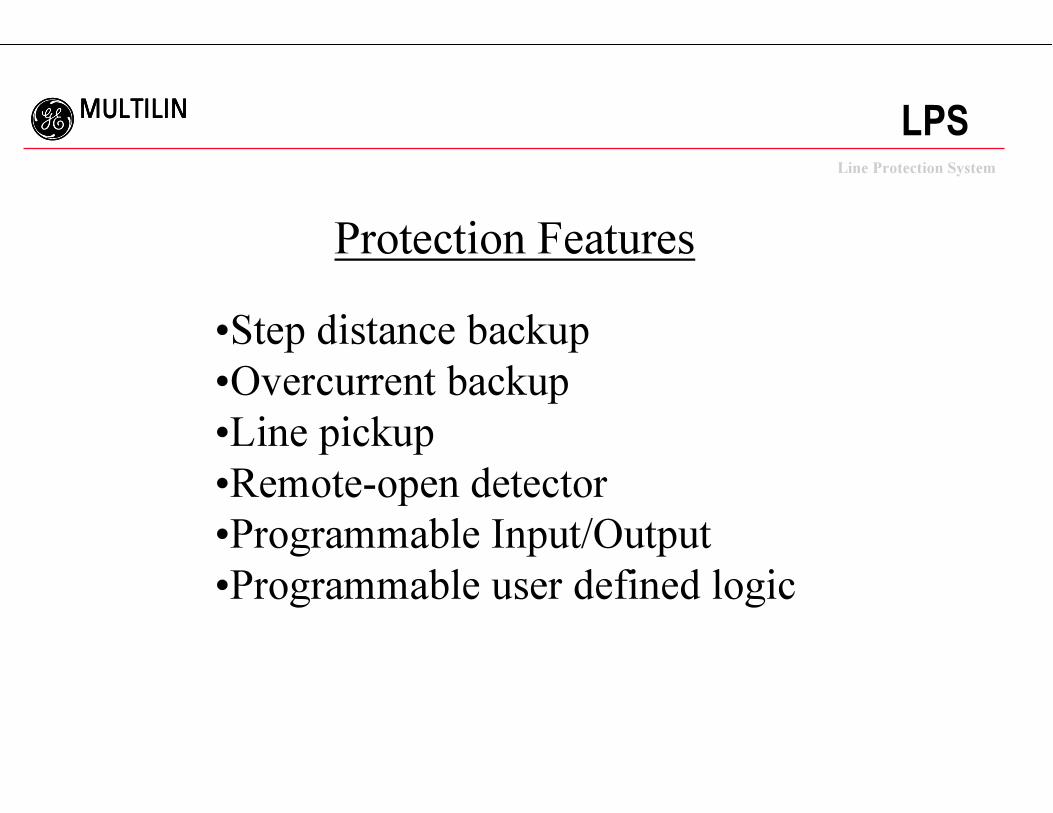
Protection Features
•Step distance backup
•Overcurrent backup
•Line pickup
•Remote-open detector
•Programmable Input/Output
•Programmable user defined logic
ggggLine Protection System
MULTILINMULTILINMULTILINMULTILINLPS
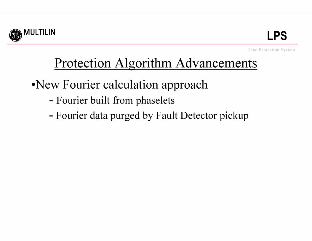
Protection Algorithm Advancements
•New Fourier calculation approach
- Fourier built from phaselets
- Fourier data purged by Fault Detector pickup
ggggLine Protection System
MULTILINMULTILINMULTILINMULTILINLPS
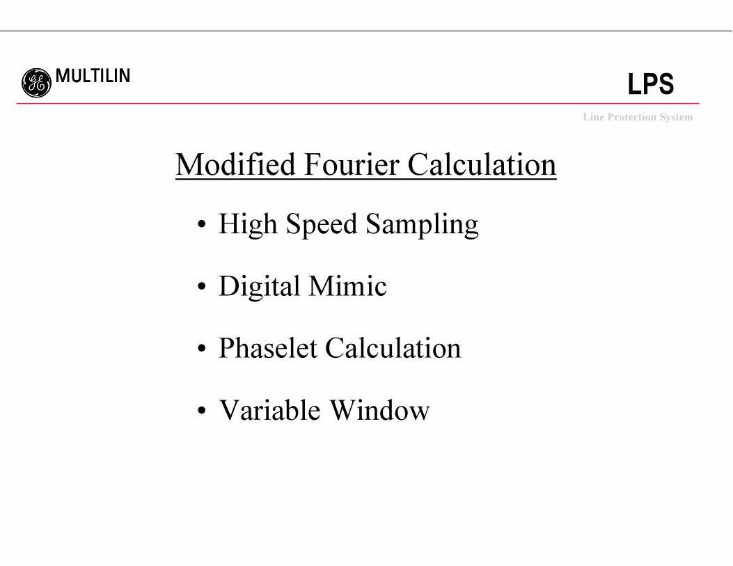
Modified Fourier Calculation
• High Speed Sampling
• Digital Mimic
• Phaselet Calculation
• Variable Window
ggggLine Protection System
MULTILINMULTILINMULTILINMULTILINLPS
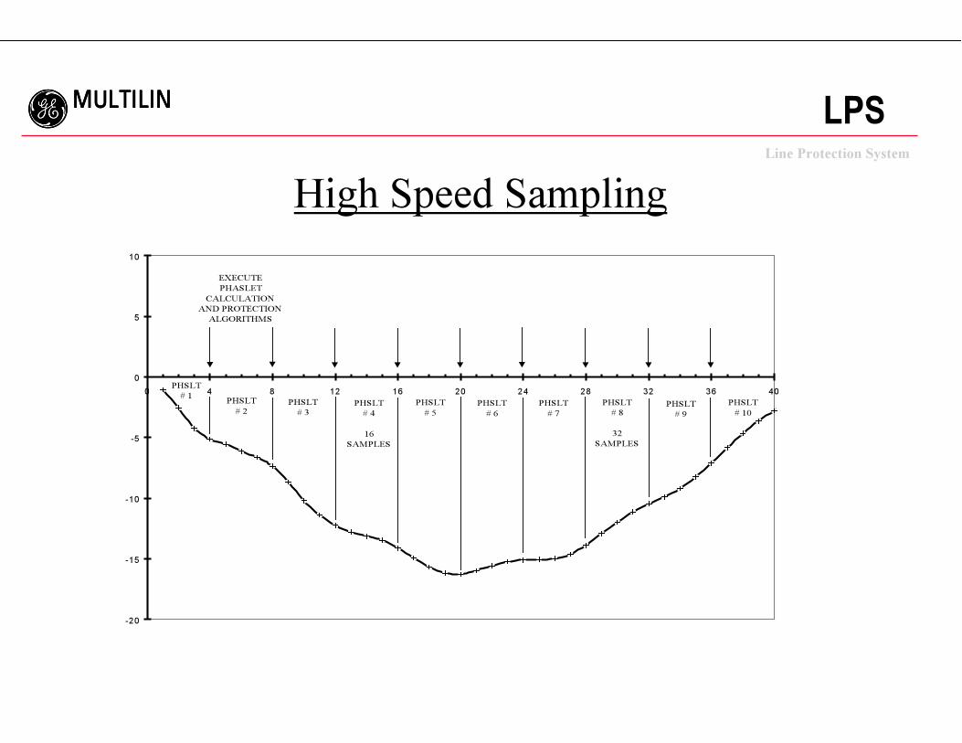
High Speed Sampling
-20
-15
-10
-5
0
5
10
0 4 8 12 16 20 24 28 32 36 40
PHSLT
# 4
16
SAMPLES
PHSLT
# 8
32
SAMPLES
EXECUTE
PHASLET
CALCULATION
AND PROTECTION
ALGORITHMS
PHSLT
# 1PHSLT
# 2
PHSLT
# 3
PHSLT
# 5
PHSLT
# 6
PHSLT
# 7
PHSLT
# 9
PHSLT
# 10
ggggLine Protection System
MULTILINMULTILINMULTILINMULTILINLPS
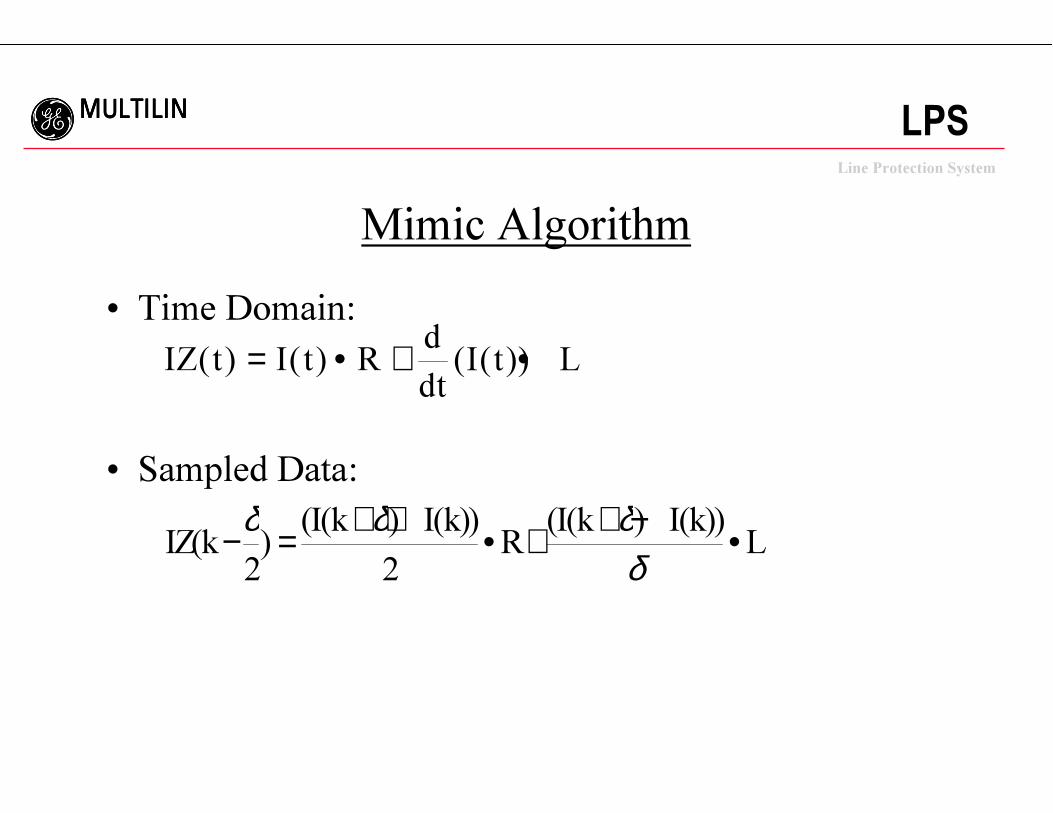
Mimic Algorithm
• Time Domain:
• Sampled Data:
IZ t I t Rd
dtI t L( ) ( ) ( ( ))= • + •
IZ kI k I k
RI k I k
L( )( ( ) ( )) ( ( ) ( ))− = + + • + + − •δ δ δ
δ2 2
ggggLine Protection System
MULTILINMULTILINMULTILINMULTILINLPS
Phaselet Definition
• Phaselets are partial sums of the productsof the waveform samples and thesine/cosine coefficients.
• Input signals are sampled 64 times percycle; protection algorithms are executed16 times per cycle.
• Groups of phaselets may be scaled andadded together to create a phasor.
ggggLine Protection System
MULTILINMULTILINMULTILINMULTILINLPS
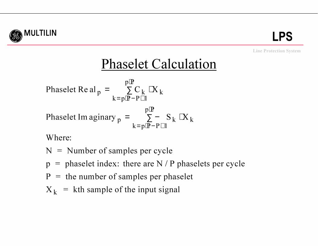
Phaselet Calculation
Phaselet al C X
Phaselet aginary S X
Where
p kk p P P
p P
k
pk p P P
p P
k k
Re
Im
:
= ∑ ⋅
= −∑ ⋅
= ⋅ − +
⋅
= ⋅ − +
⋅1
1
N = Number of samples per cycle
p = phaselet index: there are N / P phaselets per cycle
P = the number of samples per phaselet
X = kth sample of the input signalk
ggggLine Protection System
MULTILINMULTILINMULTILINMULTILINLPS
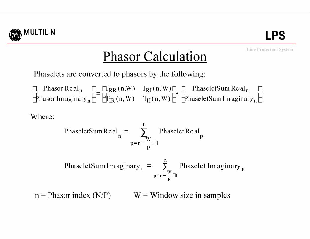
Phasor Calculation
Phasor al
Phasor aginary
T nW T n W
T n W T n W
PhaseletSum al
PhaseletSum aginary
n
n
RR RI
IR II
n
n
Re
Im
( , ) ( , )
( , ) ( , )
Re
Im
=
•
Phaselets are converted to phasors by the following:
Where:
PhaseletSum al Phaselet aln p
p nW
P
n
Re Re== − +
∑1
PhaseletSum aginary Phaselet aginaryn p
p nW
P
n
Im Im= ∑= − +1
n = Phasor index (N/P) W = Window size in samples
ggggLine Protection System
MULTILINMULTILINMULTILINMULTILINLPS
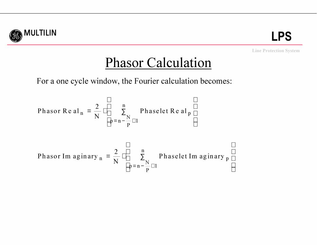
For a one cycle window, the Fourier calculation becomes:
Phaso r alN
Phase le t a l
Ph aso r ag in aryN
Phase le t ag in ary
n p
p nN
P
n
n p
p nN
P
n
R e R e
Im Im
= ⋅ ∑
= ⋅ ∑
= − +
= − +
2
2
1
1
Phasor Calculation
ggggLine Protection System
MULTILINMULTILINMULTILINMULTILINLPS
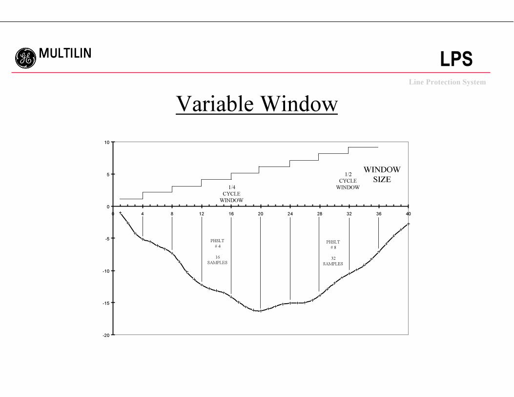
Variable Window
-20
-15
-10
-5
0
5
10
0 4 8 12 16 20 24 28 32 36 40
WINDOW
SIZE1/2
CYCLE
WINDOW1/4
CYCLE
WINDOW
PHSLT
# 4
16
SAMPLES
PHSLT
# 8
32
SAMPLES
ggggLine Protection System
MULTILINMULTILINMULTILINMULTILINLPS
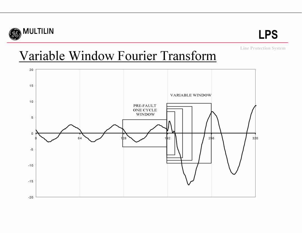
Variable Window Fourier Transform
-20
-15
-10
-5
0
5
10
15
20
0 64 128 192 256 320
PRE-FAULT
ONE CYCLE
WINDOW
VARIABLE WINDOW
ggggLine Protection System
MULTILINMULTILINMULTILINMULTILINLPS
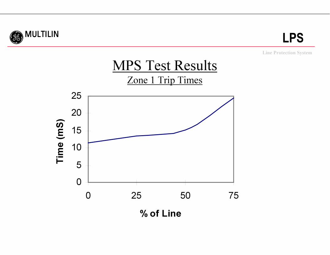
MPS Test ResultsZone 1 Trip Times
0
5
10
15
20
25
0 25 50 75
% of Line
Tim
e (mS)
ggggLine Protection System
MULTILINMULTILINMULTILINMULTILINLPS
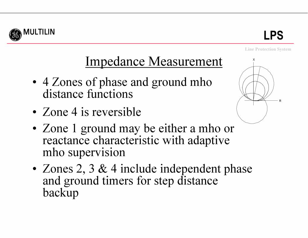
Impedance Measurement
• 4 Zones of phase and ground mhodistance functions
• Zone 4 is reversible
• Zone 1 ground may be either a mho orreactance characteristic with adaptivemho supervision
• Zones 2, 3 & 4 include independent phaseand ground timers for step distancebackup
R
X
ggggLine Protection System
MULTILINMULTILINMULTILINMULTILINLPS
Overcurrent Functions
• Fault Detector (FD)
• Distance function supervision (IT, IB)
• Phase & ground instantaneous units (50, 50G)
• Ground time overcurrent (51G)
• Instantaneous & TOC may be directionallycontrolled.
• Unbalanced current alarm (CT intergrity)
• Overload alarm (2 level)
ggggLine Protection System
MULTILINMULTILINMULTILINMULTILINLPS
Directional Functions
• Forward and reverse negative sequencedirectional functions with adjustablecompensation (NT, NB)
• Use in ground directional overcurrentprotection (IPT, IPB)
• Supervise instantaneous & time overcurrentfunctions
ggggLine Protection System
MULTILINMULTILINMULTILINMULTILINLPS
Voltage Functions
• Positive sequence undervoltage detector
• 3 fixed pickup undervoltage detectors
• 3 single phase over/undervoltage detectors
• Potential fuse failure detection logic
ggggLine Protection System
MULTILINMULTILINMULTILINMULTILINLPS
Pilot Schemes
• Blocking
• PUTT
• POTT1 - Standard permissive overreaching• POTT2 - POTT with blocking functions toimprove transient blocking performance
• Hybrid - Includes Echo/Repeat logic and optionalweak infeed tripping
• Step Distance backup is included in all schemes
• Programmable logic
ggggLine Protection System
MULTILINMULTILINMULTILINMULTILINLPS
Other Protection Features
• 4 Setting Groups
• Line Pickup Logic
• Remote Open Detection for faster clearingof unbalanced faults
• Continuous Monitor
• PT Fuse Failure Detection
ggggLine Protection System
MULTILINMULTILINMULTILINMULTILINLPS
Optional Recloser
• Features:– Up to 4 Shot Attempts
– Internal, External, Both Recloser Control
– 1 Pole or 3 Pole Operation Mode
• Inputs: Outputs:– 52/b Status - Close
– 1or 3 Pole Initiate - Reclose in Progress
– Hold/Pause - Three Pole Trip Enable
– Reclose Cancel - Lockout
– Lockout
– Reset
ggggLine Protection System
MULTILINMULTILINMULTILINMULTILINLPS
Optional Synchronism Check
• Features:– Sync Check and/or Voltage Supervison
– Va, Vb, Vc, Vab, Vbc or Vca
– Voltage Supervison Options
• Live Bus Dead Line
• Dead Bus Live Line
• Dead Bus Dead Line
• Closing Delta Voltage between Line & Bus
• Closing Voltage Angle & Frequency
ggggLine Protection System
MULTILINMULTILINMULTILINMULTILINLPS
Monitoring Features
•Fault location calculation
•Event reporting
•Oscillography data capture
•Circuit breaker trip coil monitor
•Accumulated breaker duty
•Relay self test
ggggLine Protection System
MULTILINMULTILINMULTILINMULTILINLPS
Metering Features
• Local metering on LCD display
• Remote metering via communications
• True RMS calculation
• Current: Ia, Ib, Ic, and 3I0
• Voltage: Vag, Vbg, Vcg
• Frequency
• Three phase watts and vars
ggggLine Protection System
MULTILINMULTILINMULTILINMULTILINLPS
RMS Metering Values
• Compute RMS by taking the average ofsquares of each sample data
• RMS values are computed 16 times per cyclebased on a sliding window of one cycle
• Local Interface display of values is updatedonce every 4 seconds
• PC Interface display of values is updated onceevery 1 to 30 seconds (user selectable)
ggggLine Protection System
MULTILINMULTILINMULTILINMULTILINLPS
Communications Features
•Protocols•ASCII and GE-modem protocols standard•Plug-in communications protocol converter
•Communication ports•Front nine pin RS232 port•Rear 25 pin RS232 or 4 pin PhoenixRS485•Optional second rear 25 pin RS232/RS485
•All ports independently settable•Select ASCII or GE-Modem•Rear ports can be RS232 or RS485
ggggLine Protection System
MULTILINMULTILINMULTILINMULTILINLPS
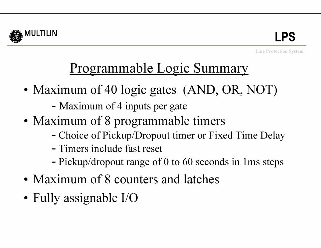
Programmable Logic Summary
• Maximum of 40 logic gates (AND, OR, NOT)
- Maximum of 4 inputs per gate
• Maximum of 8 programmable timers- Choice of Pickup/Dropout timer or Fixed Time Delay
- Timers include fast reset
- Pickup/dropout range of 0 to 60 seconds in 1ms steps
• Maximum of 8 counters and latches
• Fully assignable I/O
ggggLine Protection System
MULTILINMULTILINMULTILINMULTILINLPS
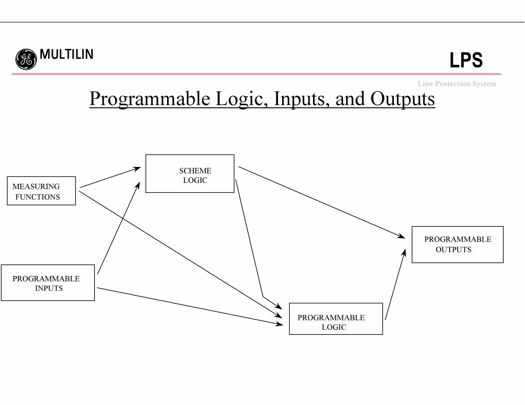
Programmable Logic, Inputs, and Outputs
PROGRAMMABLE
INPUTS
PROGRAMMABLE
LOGIC
MEASURING
FUNCTIONS
PROGRAMMABLE
OUTPUTS
SCHEME
LOGIC
ggggLine Protection System
MULTILINMULTILINMULTILINMULTILINLPS
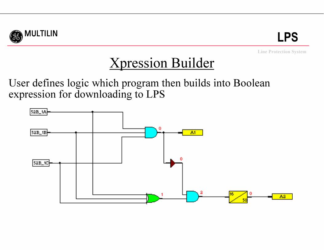
Xpression Builder
User defines logic which program then builds into Boolean expression for downloading to LPS
ggggLine Protection System
MULTILINMULTILINMULTILINMULTILINLPS
Examples of Special Logic
• Single breaker recloser
• Breaker failure
• Multi-phase fault indication
ggggLine Protection System
MULTILINMULTILINMULTILINMULTILINLPS
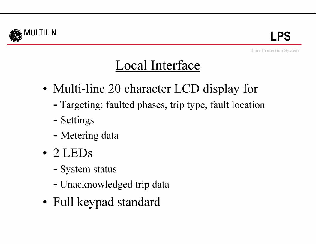
Local Interface
• Multi-line 20 character LCD display for
- Targeting: faulted phases, trip type, fault location
- Settings
- Metering data
• 2 LEDs
- System status
- Unacknowledged trip data
• Full keypad standard
ggggLine Protection System
MULTILINMULTILINMULTILINMULTILINLPS
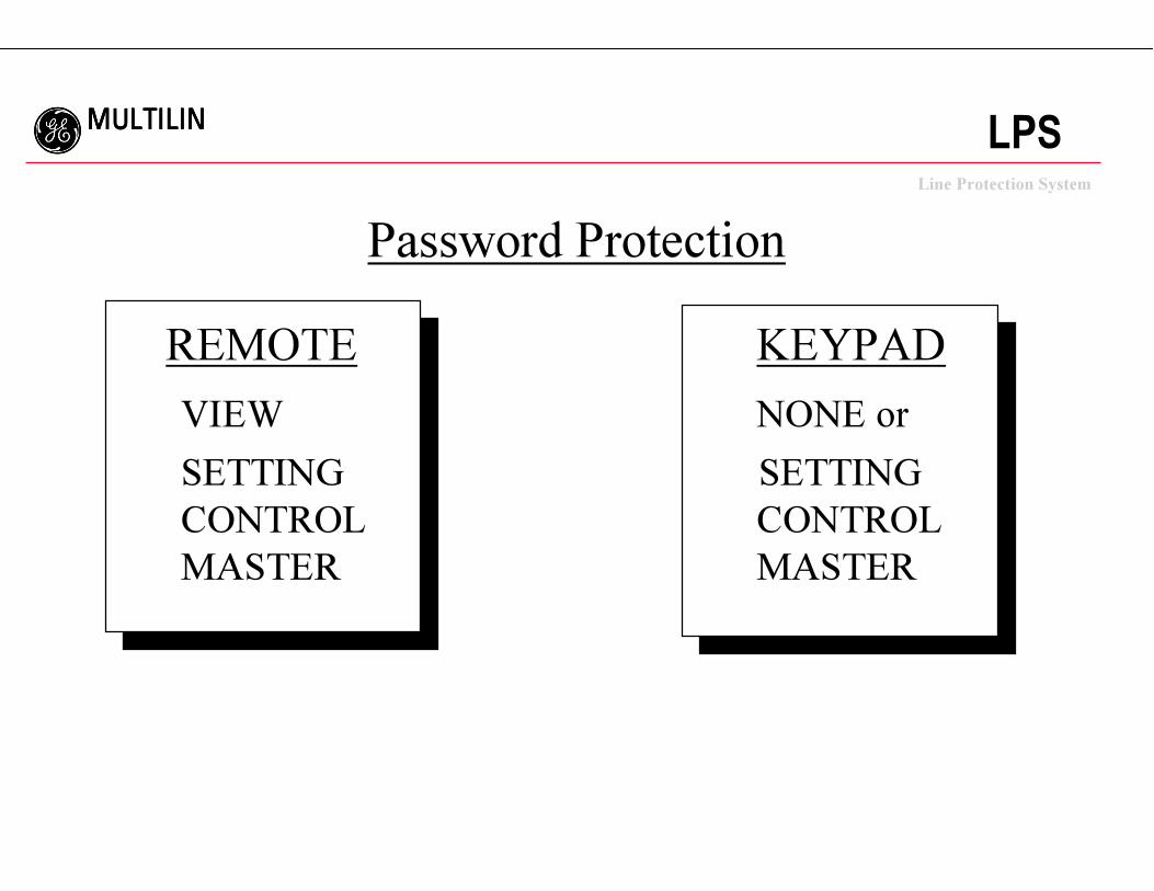
Password Protection
REMOTE KEYPAD
VIEW NONE or
SETTING SETTING
CONTROL CONTROL
MASTER MASTER
ggggLine Protection System
MULTILINMULTILINMULTILINMULTILINLPS
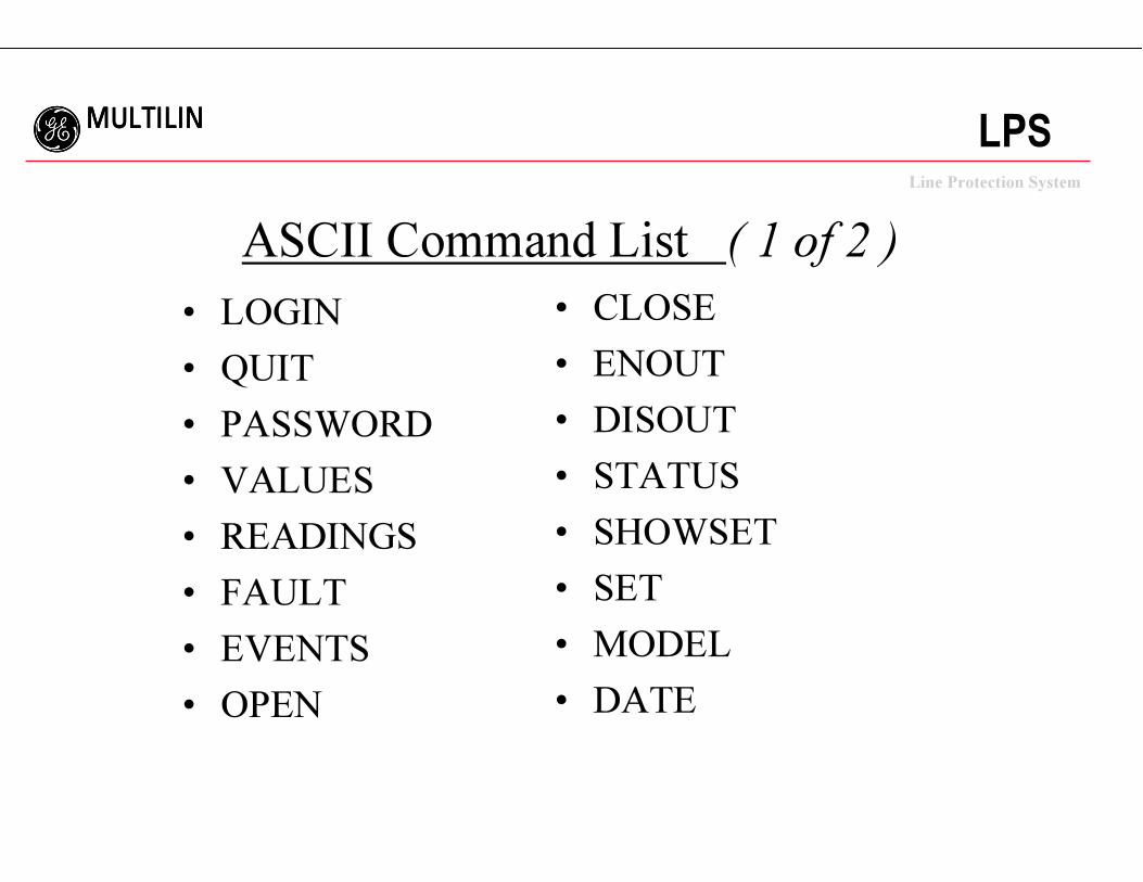
ASCII Command List ( 1 of 2 )
• LOGIN
• QUIT
• PASSWORD
• VALUES
• READINGS
• FAULT
• EVENTS
• OPEN
• CLOSE
• ENOUT
• DISOUT
• STATUS
• SHOWSET
• SET
• MODEL
• DATE
ggggLine Protection System
MULTILINMULTILINMULTILINMULTILINLPS
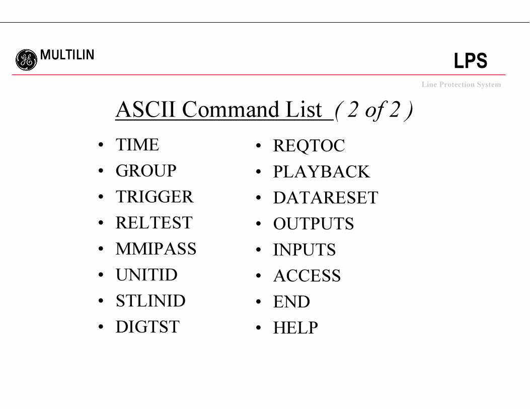
ASCII Command List ( 2 of 2 )
• TIME
• GROUP
• TRIGGER
• RELTEST
• MMIPASS
• UNITID
• STLINID
• DIGTST
• REQTOC
• PLAYBACK
• DATARESET
• OUTPUTS
• INPUTS
• ACCESS
• END
• HELP
ggggLine Protection System
MULTILINMULTILINMULTILINMULTILINLPS
Oscillography Data
• 64 samples per cycle data including:
- Currents & voltages
- Contact input & output status
- Internal sequence of events
• Flexible triggering & event storage
- 6 events at 72 cycles to 36 events at 12 cycles
• Files may be stored in COMTRADE format
ggggLine Protection System
MULTILINMULTILINMULTILINMULTILINLPS
Oscillography Data Playback
• Replay oscillography data from relay or PC
• ALPS data format
• Data run through protection algorithms & logic
• Allows testing of relay without test set
ggggLine Protection System
MULTILINMULTILINMULTILINMULTILINLPS
Support Software• ALPS-LINK:
- Windows based communications using GE-Modem
• ALPS-SET:
- Windows based settings calculations and file creation
• ALPS-TEST:
- Windows based test quantity calculation
• Xpression Builder:
- Windows based programmable logic design
• GE-DATA:
- DOS based Oscillography data analysis program• GE-OSC:
- Windows based Oscillography data analysis program
ggggLine Protection System
MULTILINMULTILINMULTILINMULTILINLPS
Upgrade Features
• Flash memory
- Upgrade without changing relay hardware
• Plug-in communications module
- Upgrade to future communications protocols
• High speed data bus access
- Future peer-to-peer communications
ggggLine Protection System
MULTILINMULTILINMULTILINMULTILINLPS
I/O Summary
• Inputs:
- Current: Ia, Ib, Ic- Voltage: Vag, Vbg, Vcg
• Digital Inputs:- 12 programmable inputs
• Demodulated IRIG-B
ggggLine Protection System
MULTILINMULTILINMULTILINMULTILINLPS
I/O Summary• Outputs:
- 24 programmable contacts
- 2 alarm contacts
Power Supply
Critical Failure
- Analog distance to fault plus faulted
phase identification for SCADA
ggggLine Protection System
MULTILINMULTILINMULTILINMULTILINLPS
Packaging
• Vertical or horizontal mounting
• 3RU 19 inch rack mount
• 5.25 X 17.25 vertical mount- Fits the cutout of EM distance relays
• Reversible mounting flanges
• Flexible projection mounting
• All boards removable from the front
ggggLine Protection System
MULTILINMULTILINMULTILINMULTILINLPS
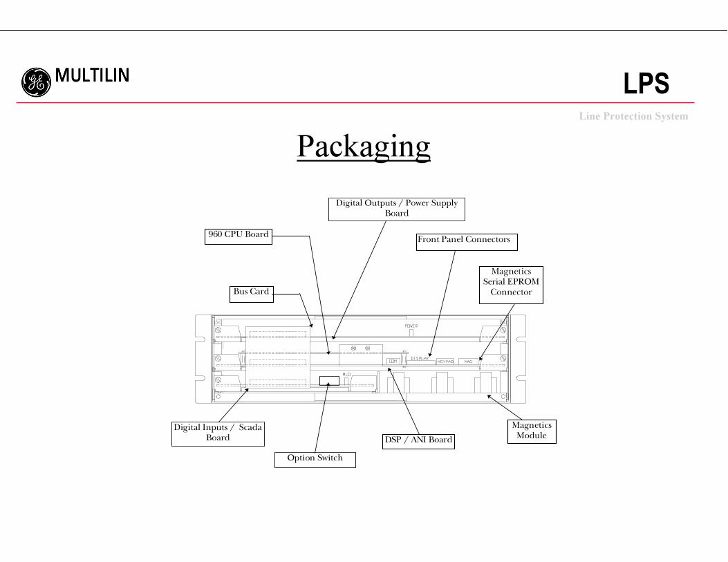
Packaging
Digital Outputs / Power SupplyBoard
Bus Card
960 CPU Board
MagneticsSerial EPROM
Connector
Front Panel Connectors
MagneticsModuleDSP / ANI Board
Digital Inputs / ScadaBoard
Option Switch
ggggLine Protection System
MULTILINMULTILINMULTILINMULTILINLPS
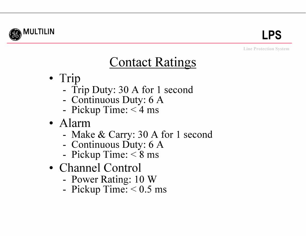
Contact Ratings
• Trip- Trip Duty: 30 A for 1 second- Continuous Duty: 6 A- Pickup Time: < 4 ms
• Alarm- Make & Carry: 30 A for 1 second- Continuous Duty: 6 A- Pickup Time: < 8 ms
• Channel Control- Power Rating: 10 W- Pickup Time: < 0.5 ms
ggggLine Protection System
MULTILINMULTILINMULTILINMULTILINLPS
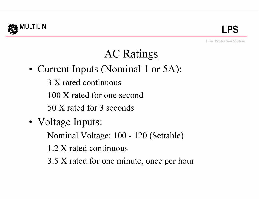
AC Ratings
• Current Inputs (Nominal 1 or 5A):
3 X rated continuous
100 X rated for one second
50 X rated for 3 seconds
• Voltage Inputs:
Nominal Voltage: 100 - 120 (Settable)
1.2 X rated continuous
3.5 X rated for one minute, once per hour
ggggLine Protection System
MULTILINMULTILINMULTILINMULTILINLPS
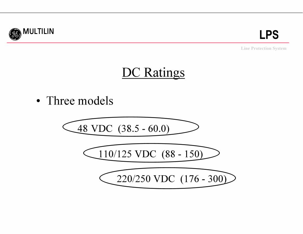
DC Ratings
• Three models
48 VDC (38.5 - 60.0)
110/125 VDC (88 - 150)
220/250 VDC (176 - 300)
ggggLine Protection System
MULTILINMULTILINMULTILINMULTILINLPS
Summary of LPS Features
• Extensive Programmable Logic and I/O
• Out of Step Tripping with Oscillography
• Flexible Communications (ASCII Included)
• Playback
• Built-In Upgradeability - Plug in Communication Card
- Flash Memory
ggggLine Protection System
MULTILINMULTILINMULTILINMULTILINLPS
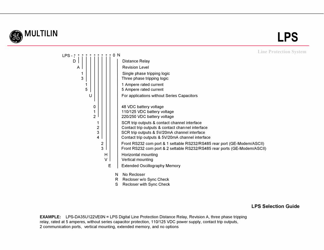
LPS Selection Guide
EXAMPLE: LPS-DA35U122VE0N = LPS Digital Line Protection Distance Relay, Revision A, three phase tripping
relay, rated at 5 amperes, without series capacitor protection, 110/125 VDC power supply, contact trip outputs,
2 communication ports, vertical mounting, extended memory, and no options
LPS -
D Distance Relay
A Revision Level
1 Single phase tripping logic
3 Three phase tripping logic
1 1 Ampere rated current
5 5 Ampere rated current
U For applications without Series Capacitors
0 48 VDC battery voltage
1 110/125 VDC battery voltage
2 220/250 VDC battery voltage
1 SCR trip outputs & contact channel interface
2 Contact trip outputs & contact channel interface
3 SCR trip outputs & 5V/20mA channel interface
4 Contact trip outputs & 5V/20mA channel interface
2 Front RS232 com port & 1 settable RS232/RS485 rear port (GE-Modem/ASCII)
3 Front RS232 com port & 2 settable RS232/RS485 rear ports (GE-Modem/ASCII)
H Horizontal mounting
V Vertical mounting
E Extended Oscillography Memory
* * * * * * * * * * 0 N
N No Recloser
R Recloser w/o Sync Check
S Recloser with Sync Check