The new French standard for the application ofcfpbolivia.com/2015/Frank/NF-EC7-design-of-deep...1...
41
Roger Frank, Ecole des ponts Sébastien Burlon, IFSTTAR The new French standard for the application of Eurocode 7 for deep foundations
Transcript of The new French standard for the application ofcfpbolivia.com/2015/Frank/NF-EC7-design-of-deep...1...

1 1
Roger Frank, Ecole des ponts Sébastien Burlon, IFSTTAR
The new French standard for the application of Eurocode 7 for deep foundations
2
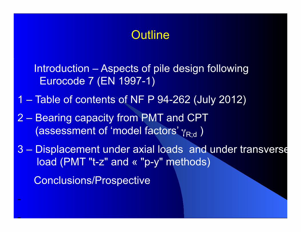
Outline
Introduction – Aspects of pile design following Eurocode 7 (EN 1997-1)
1 – Table of contents of NF P 94-262 (July 2012)
2 – Bearing capacity from PMT and CPT (assessment of ‘model factors’ γR;d )
3 – Displacement under axial loads and under transverse load (PMT "t-z" and « "p-y" methods)
Conclusions/Prospective
- -
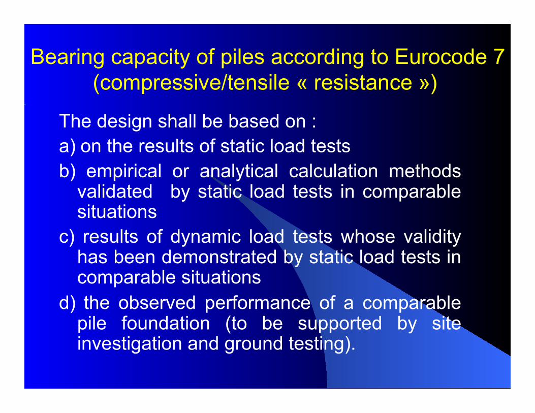
Bearing capacity of piles according to Eurocode 7(compressive/tensile « resistance »)
The design shall be based on : a) on the results of static load tests b) empirical or analytical calculation methods
validated by static load tests in comparable situations
c) results of dynamic load tests whose validity has been demonstrated by static load tests in comparable situations
d) the observed performance of a comparable pile foundation (to be supported by site investigation and ground testing).
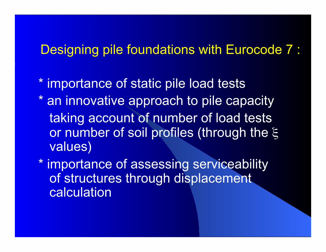
* importance of static pile load tests * an innovative approach to pile capacity
taking account of number of load tests or number of soil profiles (through the ξ values)
* importance of assessing serviceability of structures through displacement calculation
Designing pile foundations with Eurocode 7 :
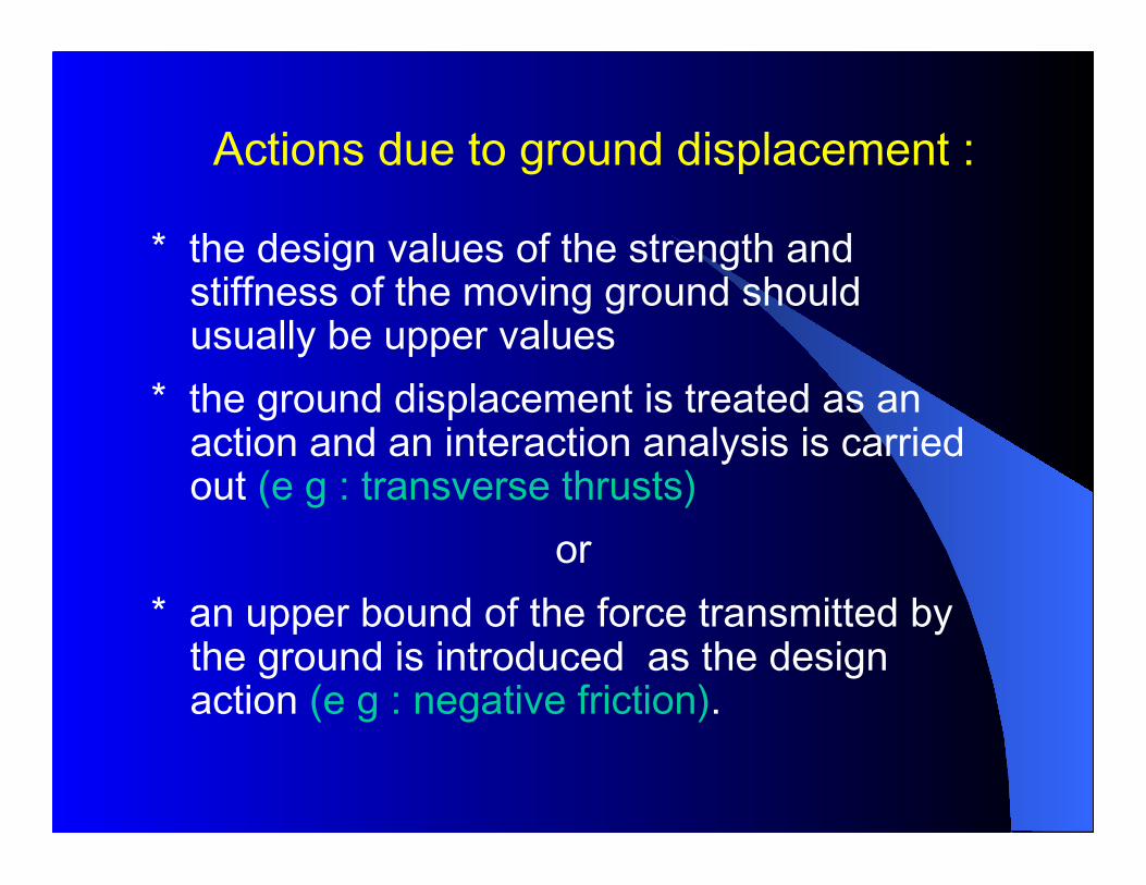
Actions due to ground displacement :
* the design values of the strength and stiffness of the moving ground should usually be upper values
* the ground displacement is treated as an action and an interaction analysis is carried out (e g : transverse thrusts)
or * an upper bound of the force transmitted by
the ground is introduced as the design action (e g : negative friction).
6
French standard for the Application of Eurocode 7 july 2012
7
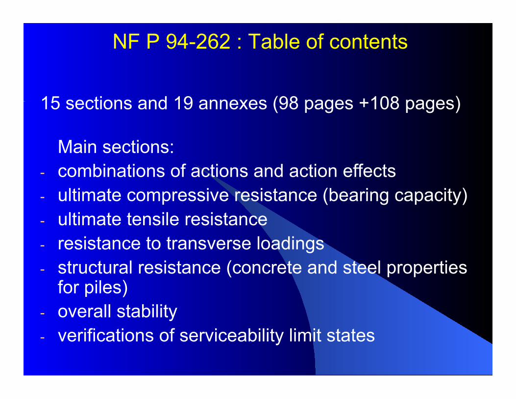
NF P 94-262 : Table of contents
15 sections and 19 annexes (98 pages +108 pages)
Main sections: - combinations of actions and action effects - ultimate compressive resistance (bearing capacity) - ultimate tensile resistance - resistance to transverse loadings - structural resistance (concrete and steel properties
for piles) - overall stability - verifications of serviceability limit states
8
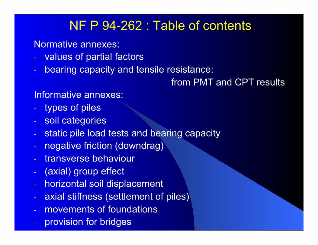
NF P 94-262 : Table of contents Normative annexes: - values of partial factors - bearing capacity and tensile resistance:
from PMT and CPT results Informative annexes: - types of piles - soil categories - static pile load tests and bearing capacity - negative friction (downdrag) - transverse behaviour - (axial) group effect - horizontal soil displacement - axial stiffness (settlement of piles) - movements of foundations - provision for bridges
9
2. Bearing capacity from PMT and CPT (assessment of ‘model factors’ γR;d )
- -
10
Background for establishing a ‘model factor’ γRd Eurocode 7 - Part 1 ‘Geotechnical design – General rules (2004), Section 7 : - requires that the validity of calculation methods be demonstrated by static load tests in comparable situation - advocates the introduction of an explicit ‘model factor’ γRd (applied to the calculation model) when designing piles from ground test results
11
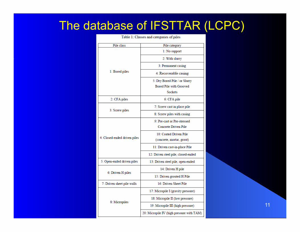
The database of IFSTTAR (LCPC)
12

13
14
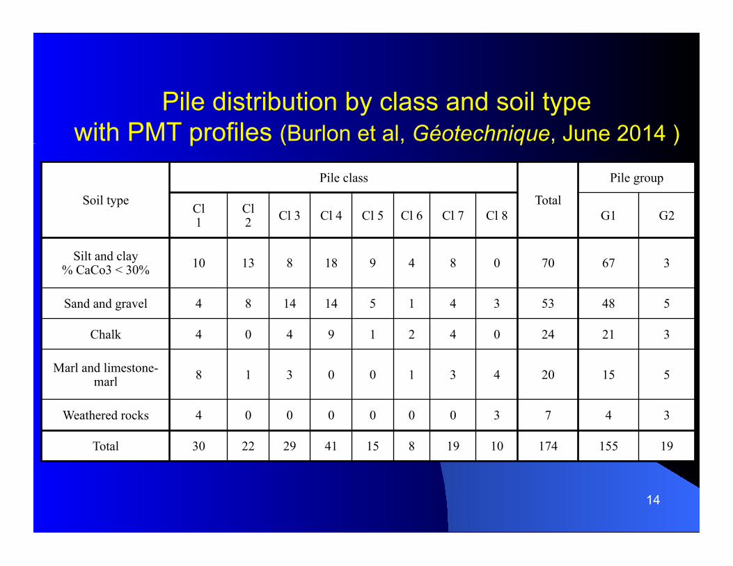
Soil type
Pile class
Total
Pile group
Cl 1
Cl 2 Cl 3 Cl 4 Cl 5 Cl 6 Cl 7 Cl 8 G1 G2
Silt and clay % CaCo3 < 30% 10 13 8 18 9 4 8 0 70 67 3
Sand and gravel 4 8 14 14 5 1 4 3 53 48 5
Chalk 4 0 4 9 1 2 4 0 24 21 3
Marl and limestone-marl 8 1 3 0 0 1 3 4 20 15 5
Weathered rocks 4 0 0 0 0 0 0 3 7 4 3
Total 30 22 29 41 15 8 19 10 174 155 19
Pile distribution by class and soil type with PMT profiles (Burlon et al, Géotechnique, June 2014 )
15
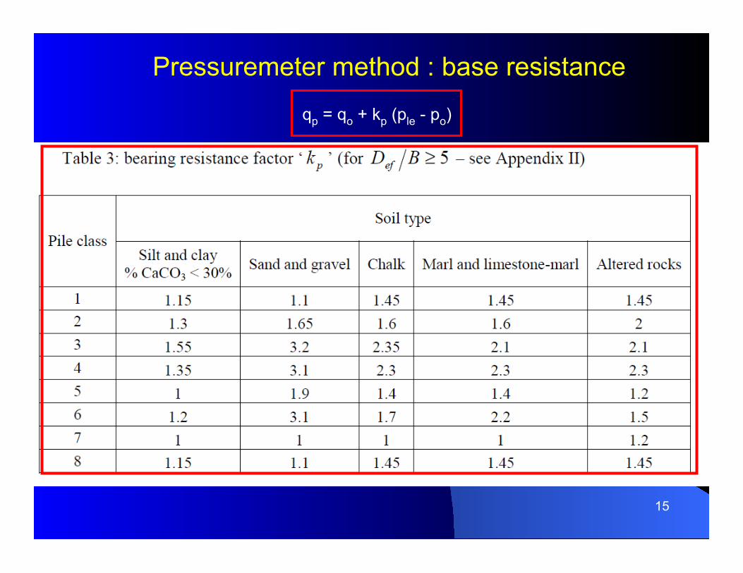
Pressuremeter method : base resistance
qp = qo + kp (ple - po)
16
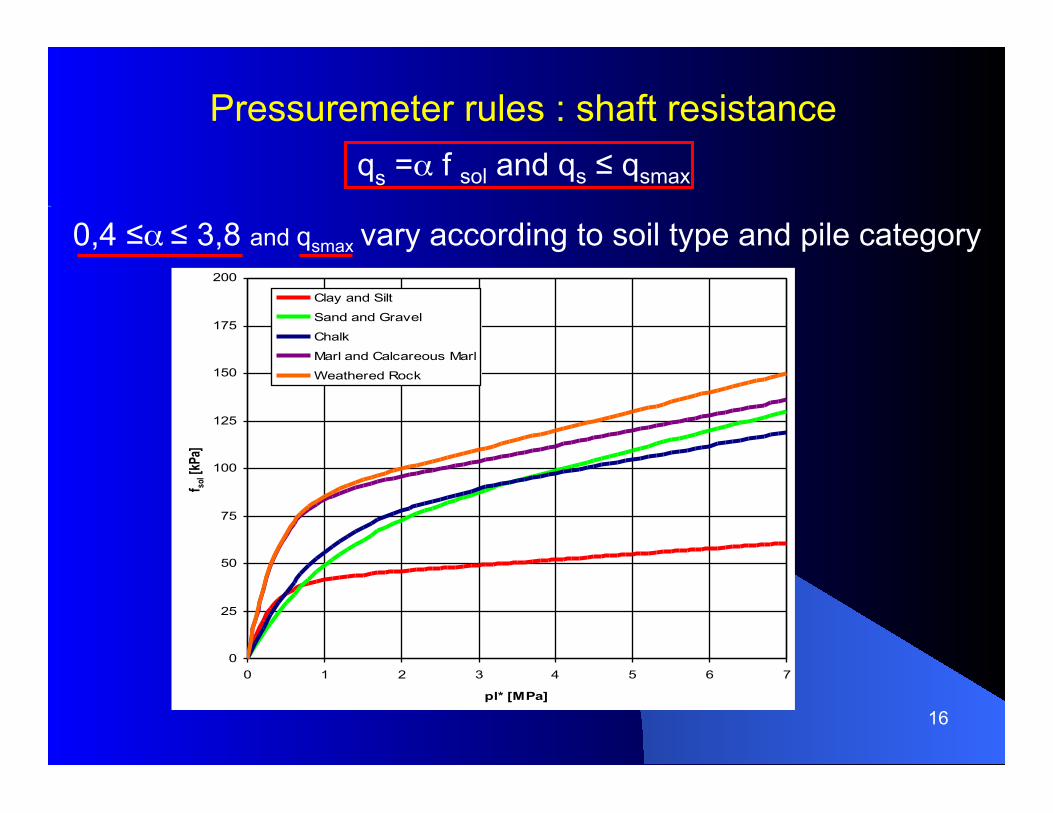
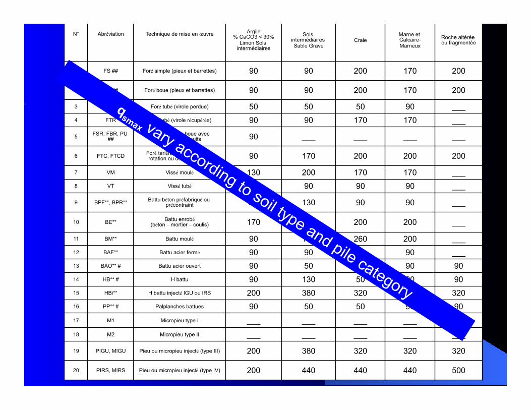
Pressuremeter rules : shaft resistance
qs =α f sol and qs ≤ qsmax f s
ol
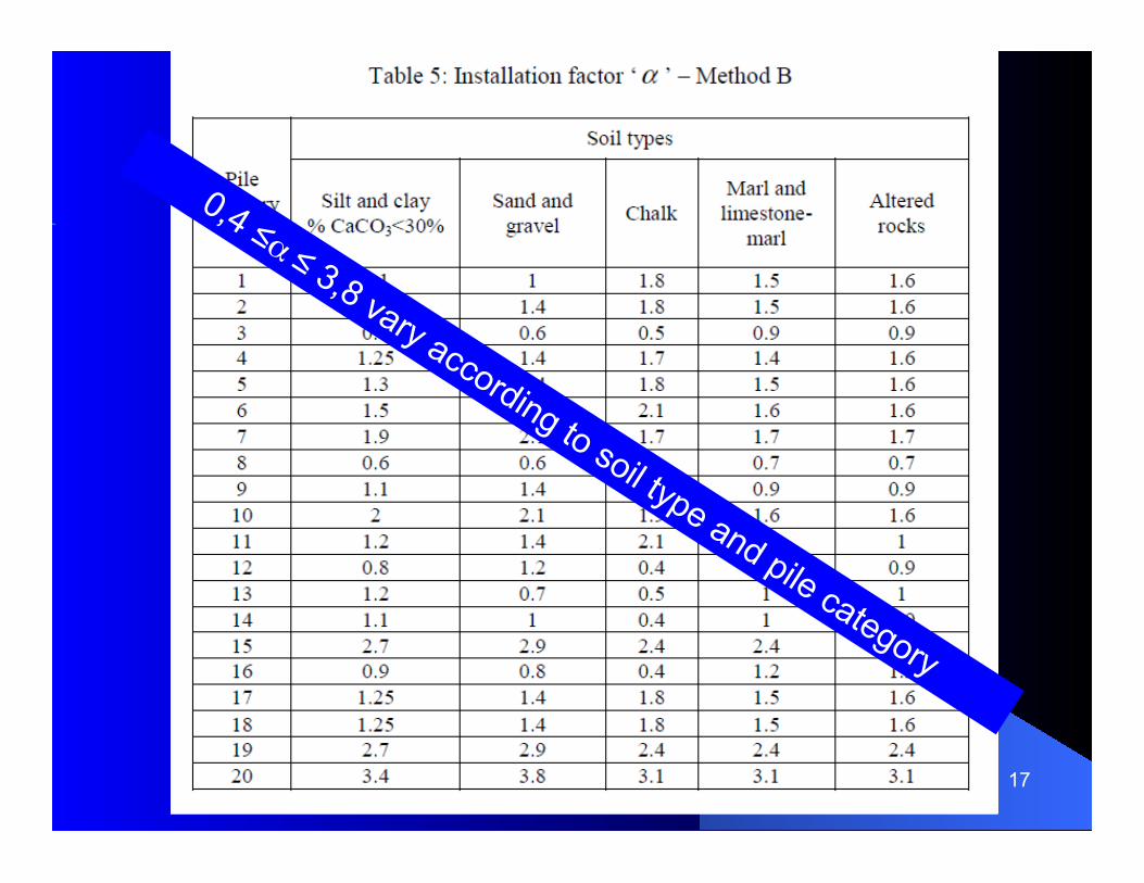
0,4 ≤α ≤ 3,8 and qsmax vary according to soil type and pile category
0
25
50
75
100
125
150
175
200
0 1 2 3 4 5 6 7
pl* [MPa]
f sol [k
Pa]
Clay and Silt
Sand and Gravel
Chalk
Marl and Calcareous Marl
Weathered Rock
17
18
N° Abréviation Technique de mise en œuvre Valeurs en kPa
Argile % CaCO3 < 30%
Limon Sols intermédiaires
Sols intermédiaires Sable Grave Craie Marne et
Calcaire-Marneux Roche altérée
ou fragmentée
1 FS ## Foré simple (pieux et barrettes) 90 90 200 170 200
2 FB ## Foré boue (pieux et barrettes) 90 90 200 170 200
3 FTP Foré tubé (virole perdue) 50 50 50 90 ___ 4 FTR Foré tubé (virole récupérée) 90 90 170 170 ___
5 FSR, FBR, PU ## Foré simple ou boue avec
rainurage ou puits 90 ___ ___ ___ ___
6 FTC, FTCD Foré tarière continue simple rotation ou double rotation 90 170 200 200 200
7 VM Vissé moulé 130 200 170 170 ___ 8 VT Vissé tubé 50 90 90 90 ___
9 BPF**, BPR** Battu béton préfabriqué ou précontraint 130 130 90 90 ___
10 BE** Battu enrobé (béton – mortier – coulis) 170 260 200 200 ___
11 BM** Battu moulé 90 130 260 200 ___ 12 BAF** Battu acier fermé 90 90 50 90 ___ 13 BAO** # Battu acier ouvert 90 50 50 90 90 14 HB** # H battu 90 130 50 90 90 15 HBi** H battu injecté IGU ou IRS 200 380 320 320 320 16 PP** # Palplanches battues 90 50 50 90 90 17 M1 Micropieu type I ___ ___ ___ ___ ___ 18 M2 Micropieu type II ___ ___ ___ ___ ___
19 PIGU, MIGU Pieu ou micropieu injecté (type III) 200 380 320 320 320
20 PIRS, MIRS Pieu ou micropieu injecté (type IV) 200 440 440 440 500
19
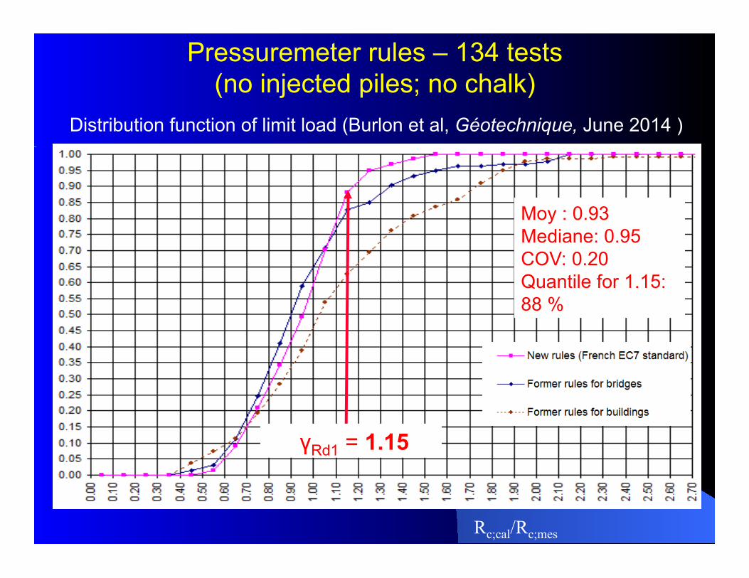
Pressuremeter rules – 134 tests (no injected piles; no chalk)
Rc;cal/Rc;mes
Distribution function of limit load (Burlon et al, Géotechnique, June 2014 )
Moy : 0.93 Mediane: 0.95 COV: 0.20 Quantile for 1.15: 88 %
γRd1 = 1.15
20
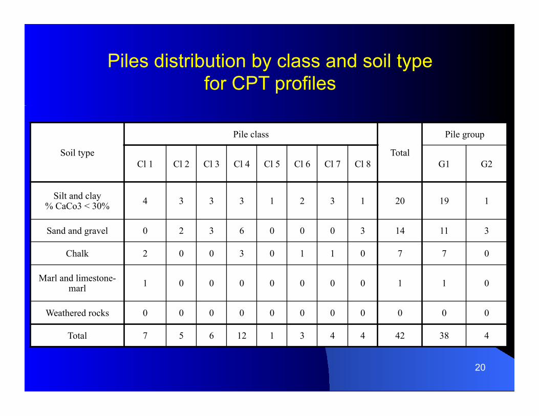
Soil type
Pile class
Total
Pile group
Cl 1 Cl 2 Cl 3 Cl 4 Cl 5 Cl 6 Cl 7 Cl 8 G1 G2
Silt and clay % CaCo3 < 30% 4 3 3 3 1 2 3 1 20 19 1
Sand and gravel 0 2 3 6 0 0 0 3 14 11 3
Chalk 2 0 0 3 0 1 1 0 7 7 0
Marl and limestone-marl 1 0 0 0 0 0 0 0 1 1 0
Weathered rocks 0 0 0 0 0 0 0 0 0 0 0
Total 7 5 6 12 1 3 4 4 42 38 4
Piles distribution by class and soil type for CPT profiles
21
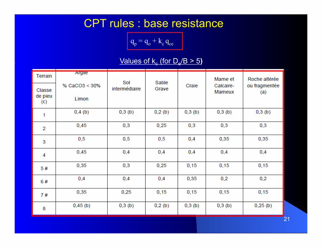
qp = qo + kc qce
Values of kc (for De/B > 5)
CPT rules : base resistance
22
0
25
50
75
100
125
150
175
200
0 2 4 6 8 10 12 14 16 18 20qc [MPa]
f sol [
kPa]
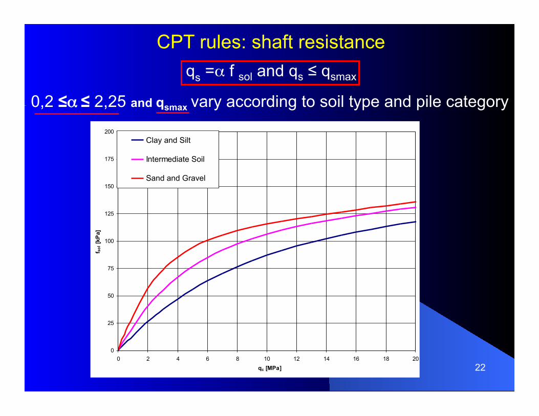
Clay and Silt
Intermediate Soil
Sand and Gravel
CPT rules: shaft resistance
qs =α f sol and qs ≤ qsmax
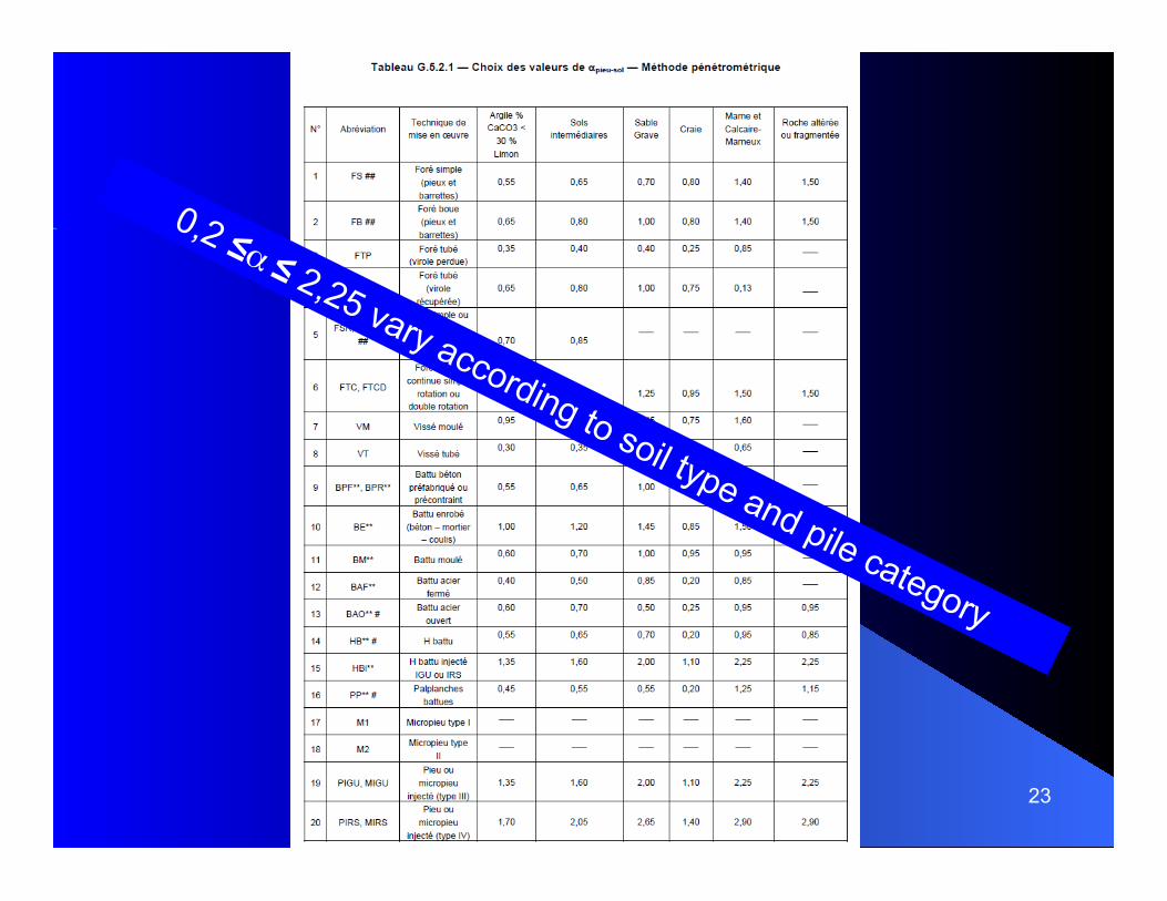
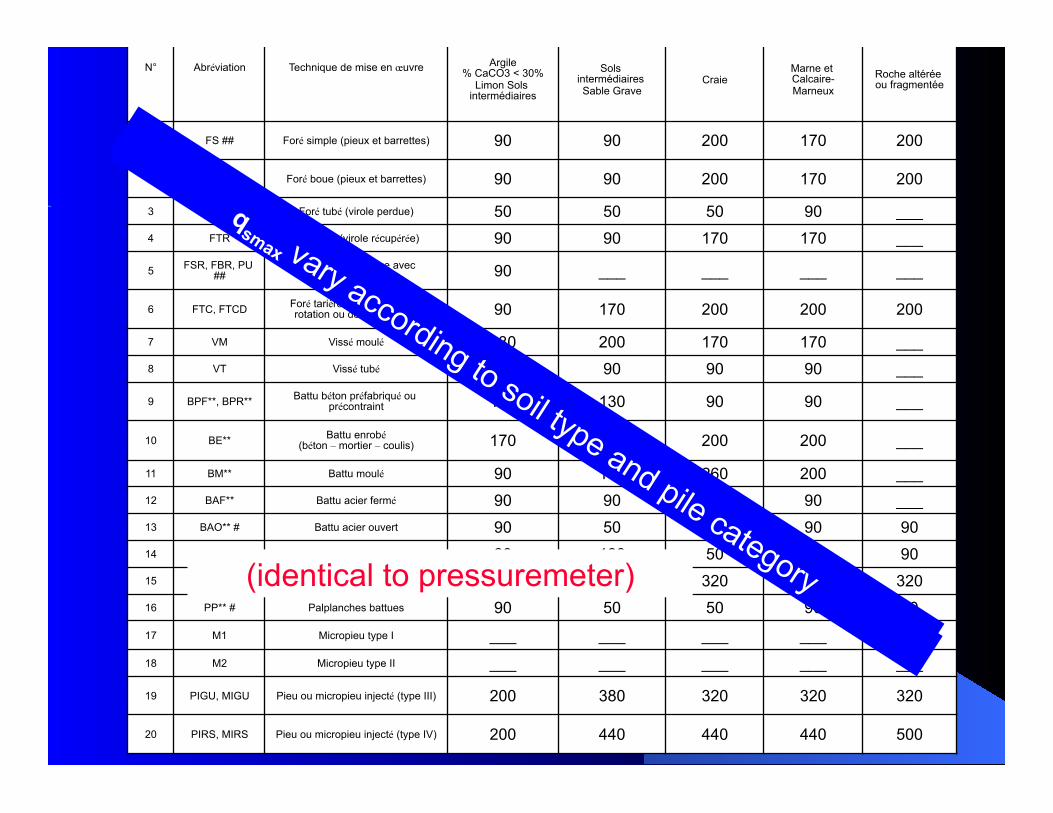
0,2 ≤α ≤ 2,25 and qsmax vary according to soil type and pile category
23
24
N° Abréviation Technique de mise en œuvre Valeurs en kPa
Argile % CaCO3 < 30%
Limon Sols intermédiaires
Sols intermédiaires Sable Grave Craie Marne et
Calcaire-Marneux Roche altérée
ou fragmentée
1 FS ## Foré simple (pieux et barrettes) 90 90 200 170 200
2 FB ## Foré boue (pieux et barrettes) 90 90 200 170 200
3 FTP Foré tubé (virole perdue) 50 50 50 90 ___ 4 FTR Foré tubé (virole récupérée) 90 90 170 170 ___
5 FSR, FBR, PU ## Foré simple ou boue avec
rainurage ou puits 90 ___ ___ ___ ___
6 FTC, FTCD Foré tarière continue simple rotation ou double rotation 90 170 200 200 200
7 VM Vissé moulé 130 200 170 170 ___ 8 VT Vissé tubé 50 90 90 90 ___
9 BPF**, BPR** Battu béton préfabriqué ou précontraint 130 130 90 90 ___
10 BE** Battu enrobé (béton – mortier – coulis) 170 260 200 200 ___
11 BM** Battu moulé 90 130 260 200 ___ 12 BAF** Battu acier fermé 90 90 50 90 ___ 13 BAO** # Battu acier ouvert 90 50 50 90 90 14 HB** # H battu 90 130 50 90 90 15 HBi** H battu injecté IGU ou IRS 200 380 320 320 320 16 PP** # Palplanches battues 90 50 50 90 90 17 M1 Micropieu type I ___ ___ ___ ___ ___ 18 M2 Micropieu type II ___ ___ ___ ___ ___
19 PIGU, MIGU Pieu ou micropieu injecté (type III) 200 380 320 320 320
20 PIRS, MIRS Pieu ou micropieu injecté (type IV) 200 440 440 440 500
(identical to pressuremeter)
25
0.00
0.05
0.10
0.15
0.20
0.25
0.30
0.35
0.40
0.45
0.50
0.55
0.60
0.65
0.70
0.75
0.80
0.85
0.90
0.95
1.00
0.00
0.10
0.20
0.30
0.40
0.50
0.60
0.70
0.80
0.90
1.00
1.10
1.20
1.30
1.40
1.50
1.60
1.70
1.80
1.90
2.00
2.10
2.20
2.30
2.40
2.50
2.60
2.70
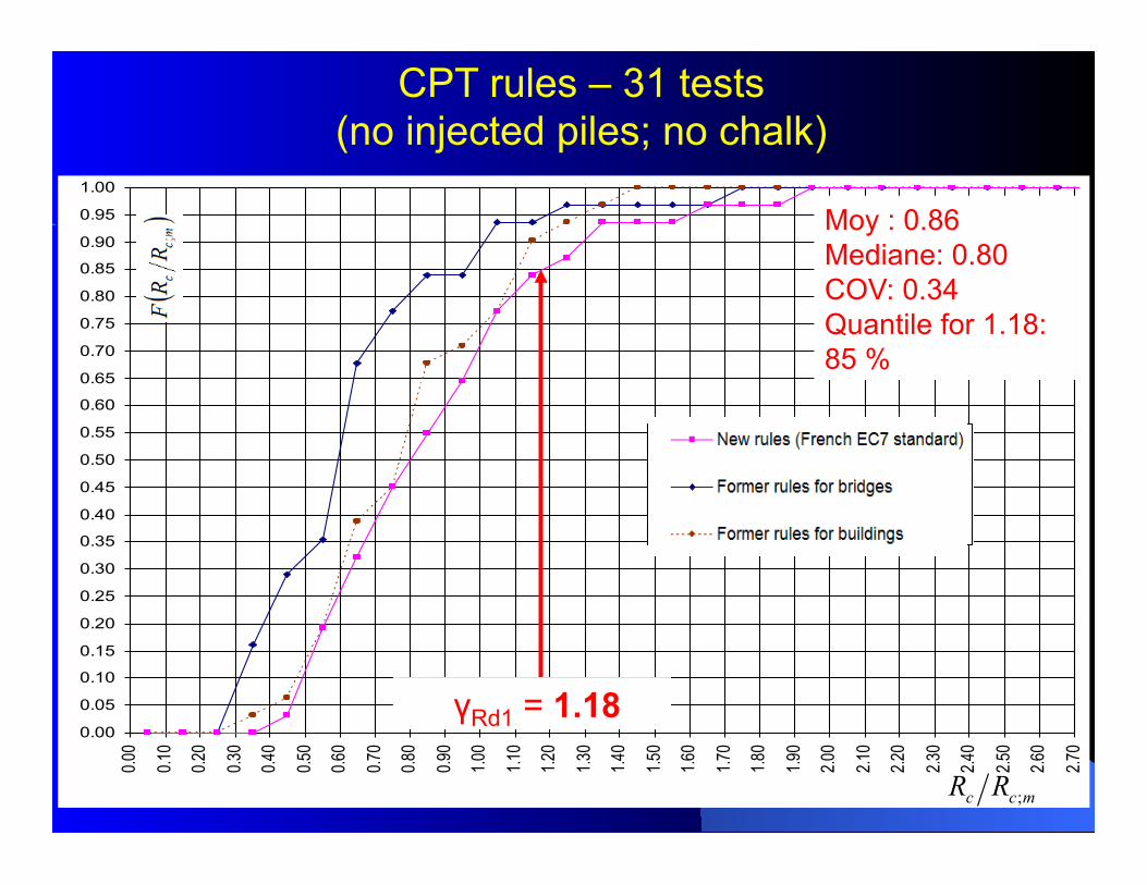
F62TV - 31 essais
DTU - 31 essais
B&G - 31 essais - Etape 4
mcc RR ;
γRd1 = 1.18
Moy : 0.86 Mediane: 0.80 COV: 0.34 Quantile for 1.18: 85 %
CPT rules – 31 tests (no injected piles; no chalk)
26
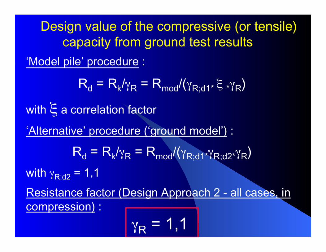
Design value of the compressive (or tensile) capacity from ground test results‘Model pile’ procedure :
Rd = Rk/γR = Rmod/(γR;d1* ξ *γR)
with ξ a correlation factor
‘Alternative’ procedure (‘ground model’) : Rd = Rk/γR = Rmod/(γR;d1*γR;d2*γR)
with γR;d2 = 1,1 Resistance factor (Design Approach 2 - all cases, in compression) : γR = 1,1
27
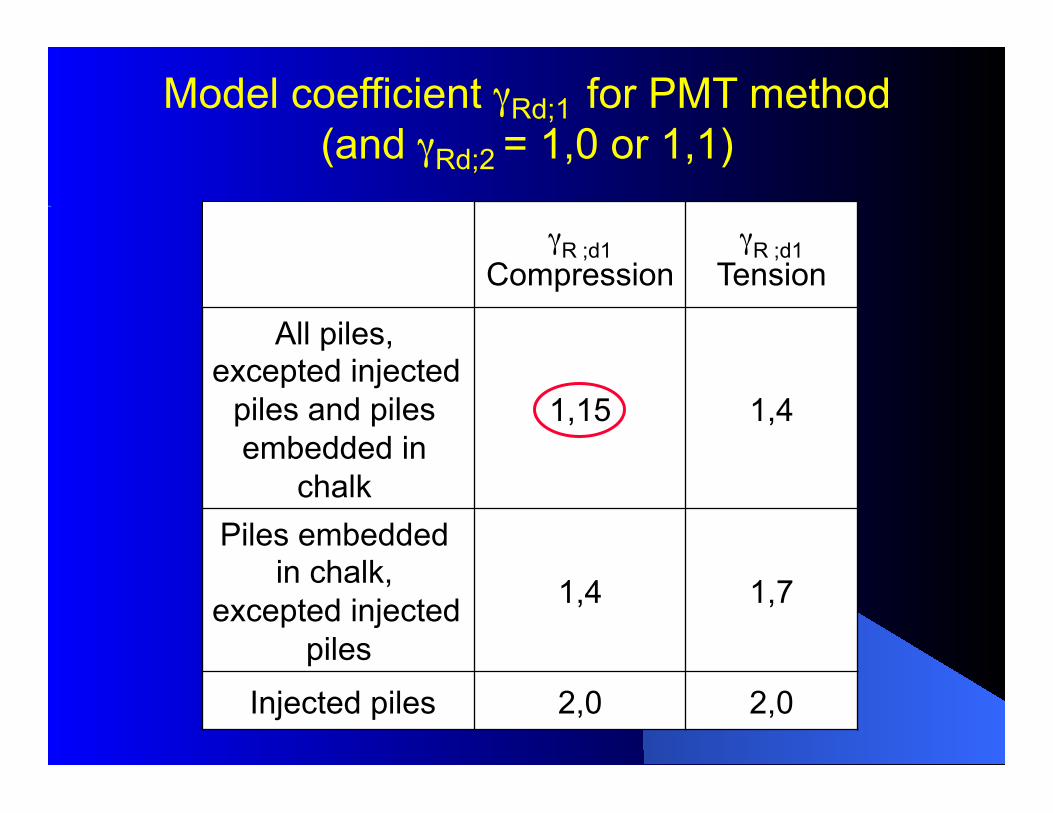
Model coefficient γRd;1 for PMT method (and γRd;2 = 1,0 or 1,1)
γR ;d1 Compression
γR ;d1 Tension
All piles, excepted injected
piles and piles embedded in
chalk
1,15 1,4
Piles embedded in chalk,
excepted injected piles
1,4 1,7
Injected piles 2,0 2,0
28
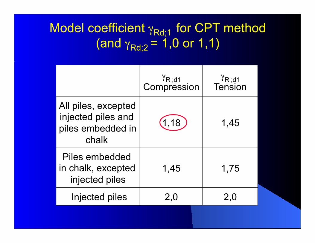
γR ;d1 Compression
γR ;d1 Tension
All piles, excepted injected piles and piles embedded in
chalk
1,18 1,45
Piles embedded in chalk, excepted
injected piles 1,45 1,75
Injected piles 2,0 2,0
Model coefficient γRd;1 for CPT method (and γRd;2 = 1,0 or 1,1)
29
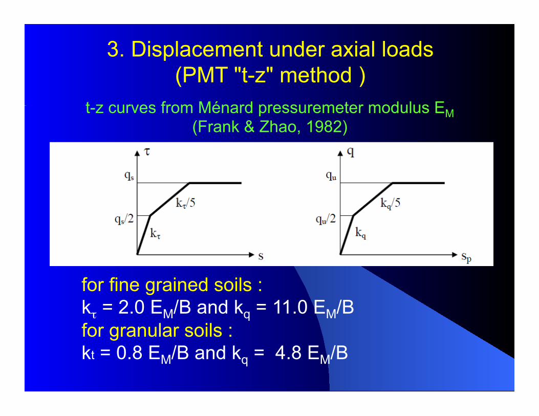
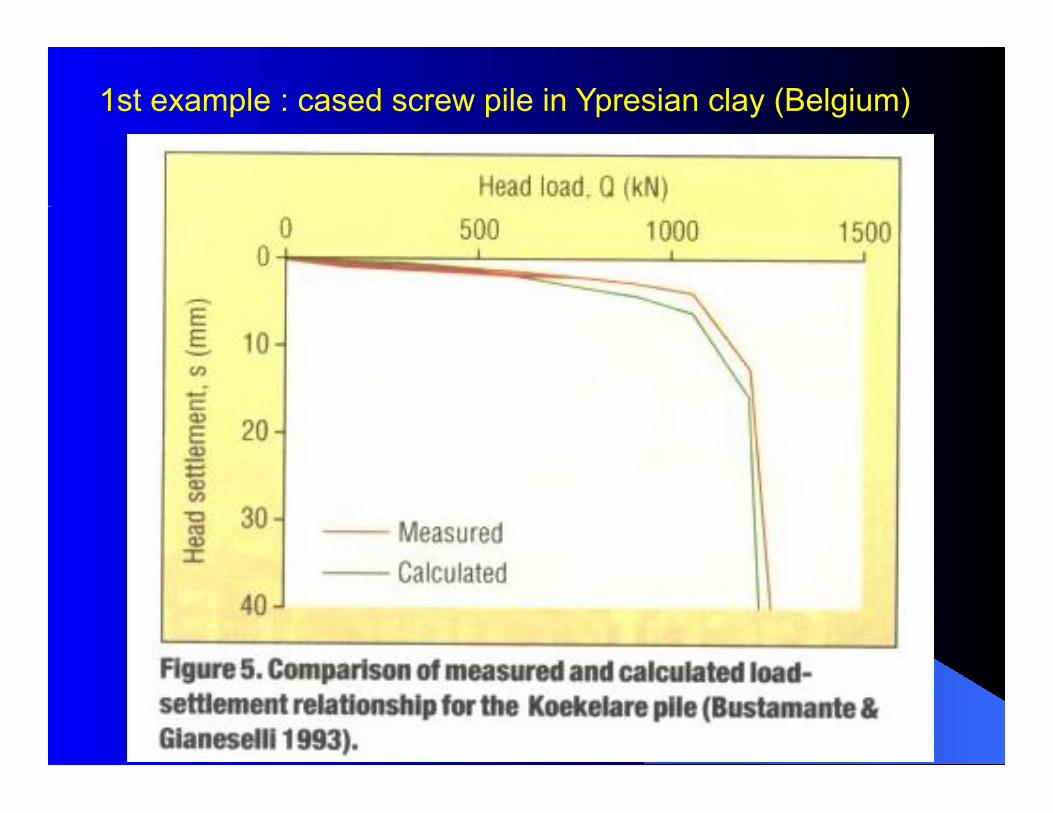
t-z curves from Ménard pressuremeter modulus EM (Frank & Zhao, 1982)
3. Displacement under axial loads (PMT "t-z" method )
for fine grained soils : kτ = 2.0 EM/B and kq = 11.0 EM/B for granular soils : kt = 0.8 EM/B and kq = 4.8 EM/B
30
1st example : cased screw pile in Ypresian clay (Belgium)
31
32
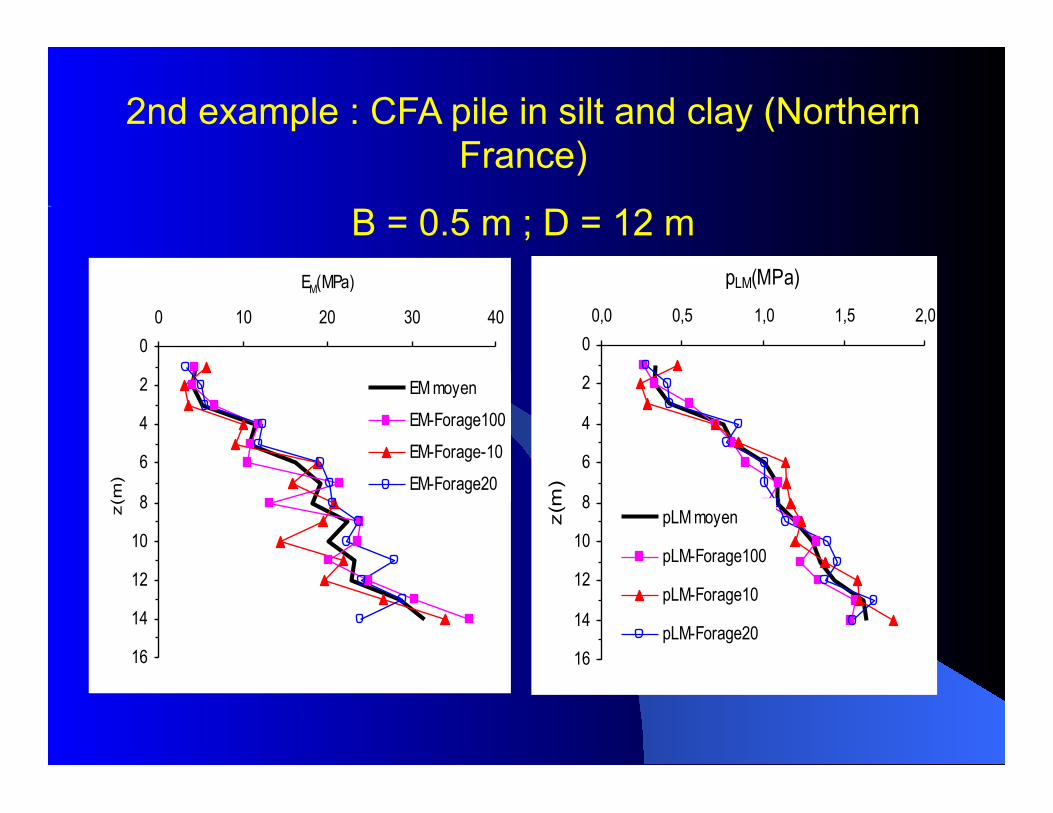
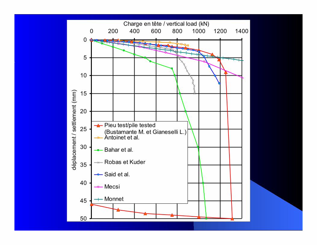
2nd example : CFA pile in silt and clay (Northern France)
B = 0.5 m ; D = 12 m
0
2
4
6
8
10
12
14
16
0 10 20 30 40
EM(MPa)
z(m
)
EM moyen
EM-Forage100
EM-Forage-10
EM-Forage20
0
2
4
6
8
10
12
14
16
0,0 0,5 1,0 1,5 2,0
pLM(MPa)
z(m
)
pLM moyen
pLM-Forage100
pLM-Forage10
pLM-Forage20
33
0
5
10
15
20
25
30
35
40
45
50
0 200 400 600 800 1000 1200 1400Charge en tête / vertical load (kN)
dépl
acem
ent /
set
tlem
ent (
mm
)
Pieu test/pile tested(Bustamante M. et Gianeselli L.)Antoinet et al.
Bahar et al.
Robas et Kuder
Said et al.
Mecsi
Monnet
34
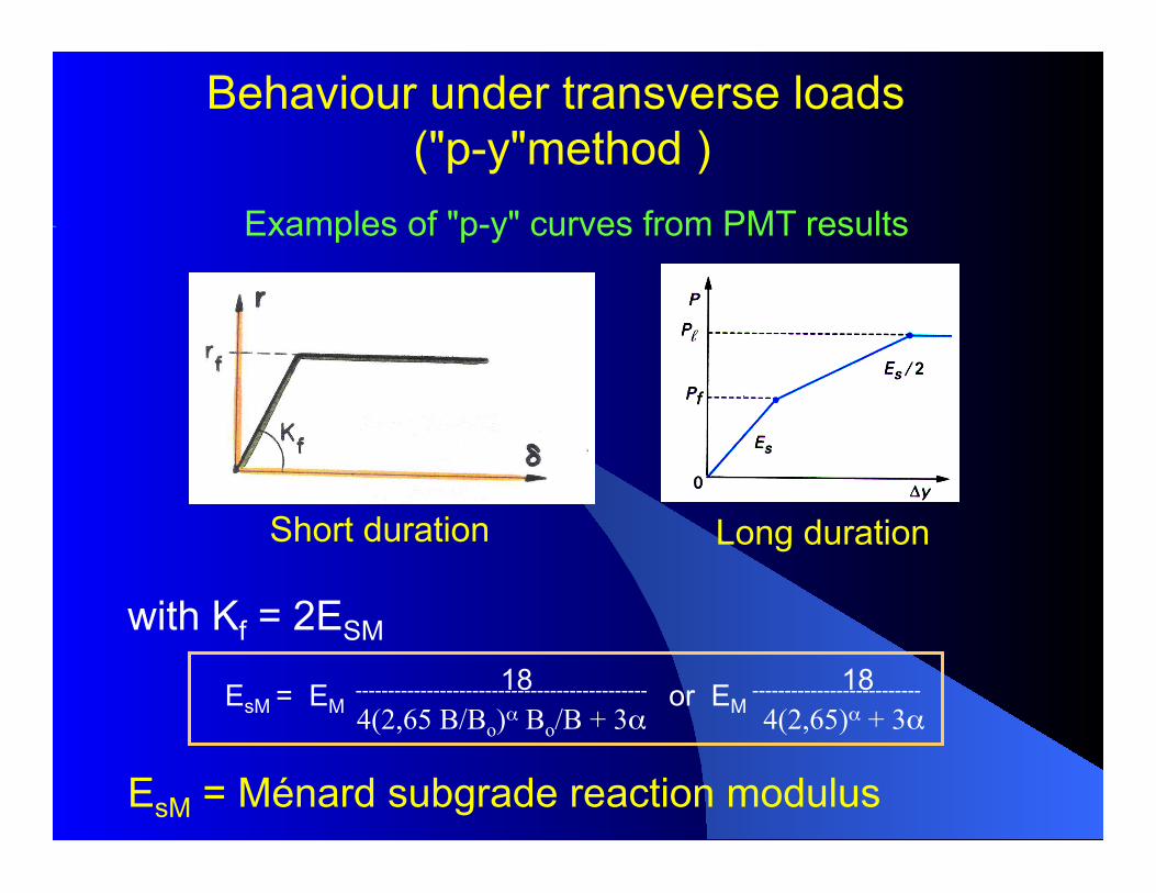
with Kf = 2ESM 18 18 EsM = EM
--------------------------------------------- or EM --------------------------
4(2,65 B/Bo)α Bo/B + 3α 4(2,65)α + 3α EsM = Ménard subgrade reaction modulus
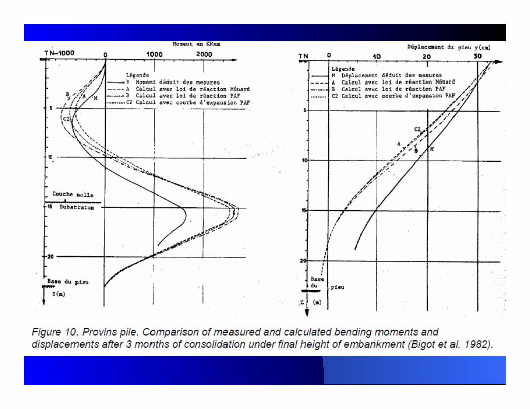
Examples of "p-y" curves from PMT results
Short duration Long duration
Behaviour under transverse loads ("p-y"method )
35
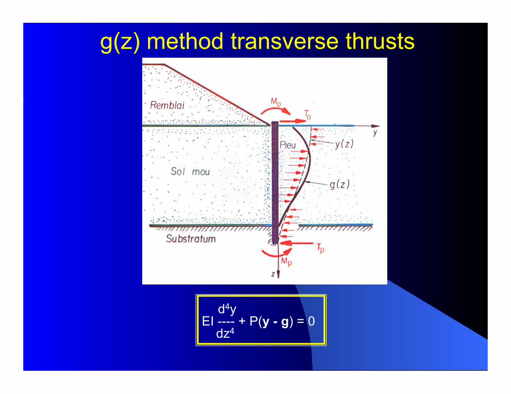
g(z) method transverse thrusts
d4y EI ---- + P(y - g) = 0 dz4
36
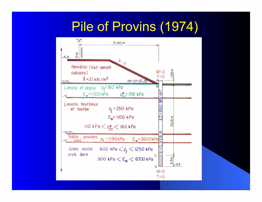
Pile of Provins (1974)
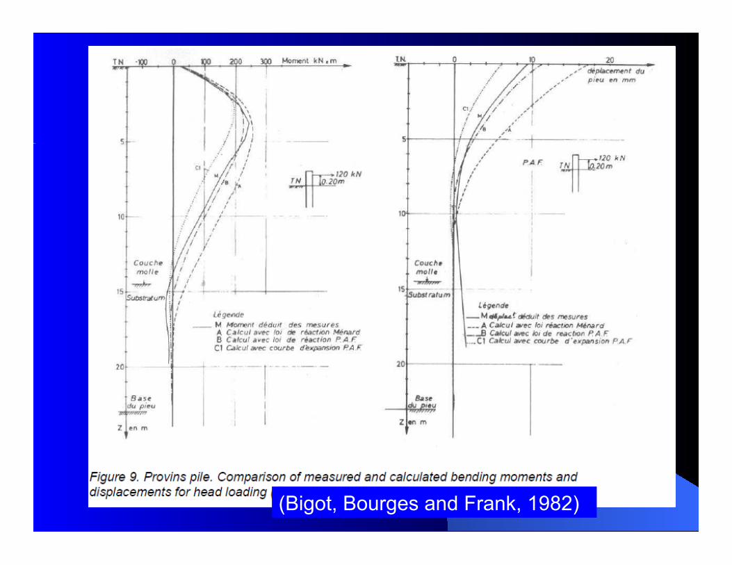
37 (Bigot, Bourges and Frank, 1982)
38
39
Conclusions/Summary
The recent PMT rules for piles have just elaborated in France (new standard for piles, compatible with Eurocode 7, 2012). They have been fully calibrated against the databank of more than 170 full scale static load tests on instrumented piles. These full scale tests were mainly conducted at the occasion of real projects/case studies. The corresponding CPT rules have also been calibrated (but there are much less data, of course).
40
Conclusions/Prospective
l In accordance with Eurocode 7 the calculation methods are based on the results of full scale load tests on piles
l The important role of displacements of foundations of structures is fully recognised (more than the safety with regard to soil failure ?…)
l Are we ready to base our SLS verifications solely on displacement assessments? … and is the structural engineer ready himself/herself?

41 41
Thank you for your attention !
Acknowledgments: