Table of Contents - Μονάδες Αριστείας of Contents About Inkscape ... Create a New...
143
This is a free, user-editable, open source software manual.
Transcript of Table of Contents - Μονάδες Αριστείας of Contents About Inkscape ... Create a New...

This is a free, user-editable, open source software manual.
Table of ContentsAbout Inkscape....................................................................................................................................................1
About SVG...........................................................................................................................................................2Objectives of the SVG Format.................................................................................................................2The Current State of SVG Software........................................................................................................2
Inkscape Interface...............................................................................................................................................3The Menu.................................................................................................................................................3The Commands Bar.................................................................................................................................3The Toolbox and Tool Controls Bar........................................................................................................4The Canvas...............................................................................................................................................4 Rulers......................................................................................................................................................5Guides......................................................................................................................................................6
How to use.........................................................................................................................................6Moving Guides...........................................................................................................................6Deleting guides...........................................................................................................................6Guide Visibility...........................................................................................................................6
Grids.........................................................................................................................................................7How to Use .......................................................................................................................................8
Enabled ......................................................................................................................................8Visible.........................................................................................................................................8Grid Units...................................................................................................................................8Origin X and Y...........................................................................................................................8Spacing X and Y.........................................................................................................................8Angle X and Y............................................................................................................................8Grid line color.............................................................................................................................8 Show dots instead of lines.........................................................................................................8
Swatches..................................................................................................................................................8How to Use .......................................................................................................................................9
Status Bar.................................................................................................................................................9
Working with files.............................................................................................................................................10Create a New Document........................................................................................................................10
Using...............................................................................................................................................10Additional Information....................................................................................................................10
Opening a Document.............................................................................................................................10Usage...............................................................................................................................................10Additional Information....................................................................................................................10
Saving files............................................................................................................................................11How to use.......................................................................................................................................11Parts.................................................................................................................................................11Type.................................................................................................................................................11Name...............................................................................................................................................12Formats............................................................................................................................................12.svg (native Inkscape)......................................................................................................................12.svg (plain).......................................................................................................................................12.svgz (compressed)..........................................................................................................................12.pdf...................................................................................................................................................12.svg (Adobe Illustrator 9+ , Adobe Illustrator)................................................................................12.outline.............................................................................................................................................12.xaml................................................................................................................................................12.png..................................................................................................................................................13.bmp.................................................................................................................................................13.wbmp..............................................................................................................................................13
i
Table of ContentsWorking with files
.ico, .cur...........................................................................................................................................13
.jpg, .jpeg.........................................................................................................................................13
.pnm, .pgm, .pbm, .ppm...................................................................................................................13
.ras...................................................................................................................................................13
.tiff...................................................................................................................................................13
.xpm, .xbm.......................................................................................................................................13
.tga, .targa........................................................................................................................................13
.pcx..................................................................................................................................................13
.ps (Postscript), .eps (encapsulated postscript), .epsi (encapsulated postscript interchange).........14
.dia (dia)...........................................................................................................................................14
.ggr (Gimp Gradient).......................................................................................................................14
.ani (animated).................................................................................................................................14
.tex...................................................................................................................................................14
.odg..................................................................................................................................................14
.dxf...................................................................................................................................................14
.pov..................................................................................................................................................14
.xcf...................................................................................................................................................14
Selector Tool......................................................................................................................................................15How to Use............................................................................................................................................15
Selecting Objects.............................................................................................................................15 Adding Objects to and Removing Objects from Selection............................................................15Rubberband Selection......................................................................................................................15Touch Selection...............................................................................................................................15Inverting Object Selection...............................................................................................................16Moving Objects...............................................................................................................................16Transforming Objects......................................................................................................................16Scaling.............................................................................................................................................17Rotating...........................................................................................................................................17Rotation Center................................................................................................................................18Skewing or Shearing.......................................................................................................................18Mirroring.........................................................................................................................................19Scaling of Stroke Width, Rectangle Corners, and Fills...................................................................19
Tips........................................................................................................................................................20
Node Tool ..........................................................................................................................................................21How to Use............................................................................................................................................21.........................................................................................................................................................21
Add Node........................................................................................................................................21.........................................................................................................................................................21Subtract Node..................................................................................................................................21..................................................................................................................................................21Join Nodes.......................................................................................................................................21..................................................................................................................................................21.........................................................................................................................................................21Joing Nodes with New Segment.....................................................................................................21..................................................................................................................................................21Split Path Between Two non-Endpoint Nodes................................................................................21Break Path at Selected Nodes..........................................................................................................21Make Selected Nodes Corner (Convert to Cusp)............................................................................22Make Selected Nodes Smooth.........................................................................................................22Make Selected Nodes Symmetric....................................................................................................22..................................................................................................................................................22Make Selected Segments Lines.......................................................................................................22Make Selected Segments Curves....................................................................................................22Convert Selected Object to Path......................................................................................................22..................................................................................................................................................22Convert Selected Object's Stroke to Paths......................................................................................22Show the Bezier Handles of Selected Nodes..................................................................................22Show Next Path Effect Parameter for Editing.................................................................................22Invert Node selection.......................................................................................................................22..................................................................................................................................................23
ii
Table of ContentsNode Tool
Hotkeys.................................................................................................................................................23Multiple select.................................................................................................................................23Near selection..................................................................................................................................23Adding nodes...................................................................................................................................23Other................................................................................................................................................23
Tips........................................................................................................................................................23
Tweak Tool.......................................................................................................................................................25 How to Use...........................................................................................................................................25
Width...............................................................................................................................................25Force................................................................................................................................................25Path editing modes..........................................................................................................................25Push.................................................................................................................................................26Shrink and Grow.............................................................................................................................26
Attract and Repel......................................................................................................................26Roughen....................................................................................................................................27Fidelity......................................................................................................................................27
Color editing modes........................................................................................................................27Channels..........................................................................................................................................28
Usage notes...............................................................................................................................28Hotkeys..................................................................................................................................................29
Zoom Tool..........................................................................................................................................................30How to use.............................................................................................................................................30
Zooming .........................................................................................................................................30Unzoom ..........................................................................................................................................30Zoom to 1:1 ....................................................................................................................................30Zoom to 1:2 ....................................................................................................................................30Zoom to 2:1 ....................................................................................................................................30Adjust selection to window ............................................................................................................30Adjust drawing to window .............................................................................................................31Adjust page to window...................................................................................................................31Adjust page width to window.........................................................................................................31Previous zoom ................................................................................................................................31Next zoom ......................................................................................................................................31
Hotkeys..................................................................................................................................................31Tips........................................................................................................................................................31
Rectangle Tool...................................................................................................................................................32How to Use............................................................................................................................................32 Hotkeys.................................................................................................................................................32
3D Box Tool.......................................................................................................................................................33 Basic Usage...........................................................................................................................................33
Drawing a 3D box...........................................................................................................................34Editing a 3D box..............................................................................................................................34Moving a 3D box.............................................................................................................................34Handling vanishing points...............................................................................................................35Rotating perspective lines...............................................................................................................35Changing mode of perspective lines...............................................................................................35
Tips........................................................................................................................................................35Inside 3D Box tool..........................................................................................................................35
iii
Table of ContentsEllipse.................................................................................................................................................................37
How to Use............................................................................................................................................37Tips........................................................................................................................................................37
Star Tool............................................................................................................................................................38How to Use............................................................................................................................................38
Options............................................................................................................................................38Drawing a Regular Polygon or Star................................................................................................38Corners............................................................................................................................................39 Spoke Ratio....................................................................................................................................39Rounded...........................................................................................................................................39Randomised.....................................................................................................................................39Default.............................................................................................................................................40Additional information....................................................................................................................40
Spiral..................................................................................................................................................................41How to use.............................................................................................................................................41Key Commands......................................................................................................................................42
Outer handle:..................................................................................................................................42 Inner handle:...................................................................................................................................42
Pencil Tool.........................................................................................................................................................43How to use.............................................................................................................................................43 Tips.......................................................................................................................................................43
Bezier with Pen Tool.........................................................................................................................................44How to use Bézier..............................................................................................................................44
Delete a Segment.............................................................................................................................44Draw a Curve...................................................................................................................................44Continue a Path...............................................................................................................................44
Tips........................................................................................................................................................44
Calligraphy Tool...............................................................................................................................................46How to Use............................................................................................................................................46
Options............................................................................................................................................46Width........................................................................................................................................46
Input Device Pressure.........................................................................................................46Drawing...........................................................................................................................................49
Adding a New Stroke to a Calligraphy Object.........................................................................49Tracking a Shape......................................................................................................................49Engraving..................................................................................................................................51
Bucket Fill Tool.................................................................................................................................................52How to use.............................................................................................................................................52
Style.................................................................................................................................................52Controls...........................................................................................................................................53
Hotkeys..................................................................................................................................................53
Text tool.............................................................................................................................................................55 How to Us.............................................................................................................................................55Special Characters..................................................................................................................................55 Tips.......................................................................................................................................................55
iv
Table of ContentsConnector Tool..................................................................................................................................................56
How to Use............................................................................................................................................56Connecting.......................................................................................................................................56Rerouting.........................................................................................................................................57Arranging.........................................................................................................................................57.........................................................................................................................................................58
Gradients...........................................................................................................................................................59How to use.............................................................................................................................................59
Types of gradients...........................................................................................................................59More colors......................................................................................................................................59Selecting multiple stops...................................................................................................................60Editing intermediate stops...............................................................................................................60Automatic duplication of gradients.................................................................................................61
Dropper Tool....................................................................................................................................................62How to Use............................................................................................................................................62Hotkeys..................................................................................................................................................63Tips........................................................................................................................................................63
Path modification Effects.................................................................................................................................64Available effects....................................................................................................................................64
Envelope and Perspective................................................................................................................64Add Nodes.......................................................................................................................................64Color Markers to Match Stroke.......................................................................................................64Flatten Beziers.................................................................................................................................65Fractalize.........................................................................................................................................65Jitter nodes.......................................................................................................................................65Straighten Segments........................................................................................................................66Whirl................................................................................................................................................66
Styling Text .......................................................................................................................................................67Text Selection........................................................................................................................................67Text Aspect............................................................................................................................................67Hot Keys................................................................................................................................................67
.............................................................................................................................................................................68
Text Effects........................................................................................................................................................69Lorem Ipsum Example...........................................................................................................................69Replace Text..........................................................................................................................................69Sentence Case........................................................................................................................................69Title Case...............................................................................................................................................70UPPER CASE........................................................................................................................................70fLIP cASE..............................................................................................................................................70lower case...............................................................................................................................................71rANdOm CasE ......................................................................................................................................71
Text and Paths...................................................................................................................................................72Put on Path / Remove from Path............................................................................................................72Flow into Frame / Unflow from Frame..................................................................................................72.........................................................................................................................................................72
Copy, Clone and Duplicate...............................................................................................................................74Introduction............................................................................................................................................74How to Use............................................................................................................................................74
Copy................................................................................................................................................74
v
Table of ContentsCopy, Clone and Duplicate
Duplicate.........................................................................................................................................74Clone...............................................................................................................................................74Unlink clone....................................................................................................................................75Select original..................................................................................................................................75
Clipping paths and masks................................................................................................................................76Introduction............................................................................................................................................76Clipping.................................................................................................................................................76Masking.................................................................................................................................................78
Introduction to Positionning ...........................................................................................................................79Raise to Top...........................................................................................................................................79Lower to Bottom....................................................................................................................................79Raise.......................................................................................................................................................79Lower.....................................................................................................................................................80
Align and Distribute.........................................................................................................................................81.............................................................................................................................................................................82
How to Use............................................................................................................................................82"Relative to"....................................................................................................................................82Align................................................................................................................................................82Distribute.........................................................................................................................................83Remove overlaps.............................................................................................................................83Connector network layout...............................................................................................................83Nodes...............................................................................................................................................83
Layers.................................................................................................................................................................84The Layers Widget on the Status Bar....................................................................................................84The Layers Dialog..................................................................................................................................84Blend Mode and Opacity.......................................................................................................................84How to Use............................................................................................................................................85
Adding Layers.................................................................................................................................85Renaming Layer..............................................................................................................................85Selecting Layers..............................................................................................................................85Moving a Selection Between Layers...............................................................................................85Moving Layers................................................................................................................................85Deleting Layers...............................................................................................................................86Locking Layers................................................................................................................................86Hiding Layers..................................................................................................................................86Blend Mode.....................................................................................................................................86Opacity............................................................................................................................................86
Grouping............................................................................................................................................................87How to Use............................................................................................................................................87
Creating and Releasing Groups.......................................................................................................87Working with Objects in a Group...................................................................................................87Selecting Objects within a Group (from outside the group)...........................................................87Adding Objects to a Group..............................................................................................................87
Introduction to Styling.....................................................................................................................................89 Fill.........................................................................................................................................................89Stroke Paint............................................................................................................................................89Stroke Width..........................................................................................................................................89
vi
Table of ContentsIntroduction to Styling
Application of Styles.............................................................................................................................89Copy Styles from Other Objects.....................................................................................................89Copy Dimensions from Other Objects............................................................................................89
Pattern Fill.........................................................................................................................................................91How to use.............................................................................................................................................91
Object to pattern..............................................................................................................................91
Stroke Style........................................................................................................................................................92How to Use............................................................................................................................................92
Creating New Markers....................................................................................................................92
Color Swatches..................................................................................................................................................93Introduction............................................................................................................................................93How to Use............................................................................................................................................93
Customize the Swatch Palette.........................................................................................................93Swatch Size...............................................................................................................................94
Small Option......................................................................................................................94Huge Option.......................................................................................................................94
Wrap..........................................................................................................................................94Shape.........................................................................................................................................94
Tall Option.........................................................................................................................94Wide Option.......................................................................................................................94
Libraries....................................................................................................................................94Create a Custom Swatch Library.....................................................................................................94
Live Path Effects...............................................................................................................................................96Details about operation..........................................................................................................................96.........................................................................................................................................................96Applying effects.....................................................................................................................................96Editing effect parameters.......................................................................................................................96Available effects....................................................................................................................................97Development of new effects..................................................................................................................97
Gears..................................................................................................................................................................98
Pattern along path.............................................................................................................................................99...............................................................................................................................................................99.........................................................................................................................................................99.........................................................................................................................................................99
Introduction to SVG Filter Effects................................................................................................................100Basics...................................................................................................................................................100Filter primitives....................................................................................................................................100Filter UI................................................................................................................................................101
Parts of the dialog..........................................................................................................................101Managing filters............................................................................................................................102Managing filter primitives.............................................................................................................102
Color Management........................................................................................................................................104Calibrated SVG Color including CMYK.............................................................................................104Display Adjustment.............................................................................................................................104Proofing...............................................................................................................................................104Operation Systems Support.................................................................................................................105Creating ICC Profiles...........................................................................................................................105
vii

Table of ContentsGenerate Template..........................................................................................................................................106
Installing Inkscape on Windows...................................................................................................................108
Create a Basic Icon.........................................................................................................................................114Create New Icon File ..........................................................................................................................114Save the File.........................................................................................................................................114Start Work............................................................................................................................................115Exporting to PNG................................................................................................................................121
License..............................................................................................................................................................123
Authors............................................................................................................................................................124
General Public License..................................................................................................................................130
viii
About InkscapeInkscape is an open source drawing tool for creating and editing SVG graphics. More than just a text vectoreditor, Inkscape provides a WYSIWYG interface for manipulation of vector images, allowing the artist toexpress himself freely. While other free and proprietary software exists with similar capabilities, Inkscapeprovides an interface to directly manipulate the underlying SVG code, which allows one to be certain that thecode is in compliance with W3C standards. Since the beginning of its development, the Inkscape project hasbeen a very active, providing stability for the current software and growth of capacities in the future.
Like other drawing programs, Inkscape offers creation of basic shapes (such as ellipses, rectangles, stars,polygons and spirals) as well as the ability to transform and manipulate these basic shapes by rotation,stretching and skewing.
Inkscape also offers functionality to manipulate objects more precisely by adjusting node points and curves. These functions are indispensable to useful drawing software, and allow the advanced artist to freely createwhat he imagines.
The properties of objects can either be manipulated individually and precisely through the XML editor, ormore generally in an intuitive fashion by input devices such as mice, pen tablets or even touch screen.
In addition, Inkscape allows one to insert text and bitmaps (such as PNG, another W3C recommended bitmapimage format) into an image as well as perform some basic editing functions on them. If further bitmapediting is required, other tools may be used (such as the GIMP) on images before importing them or after. Infact, if a linked bitmap is edited in another program, Inkscape will reflect these changes once the SVG isreloaded.
All of these characteristics make Inkscape a model drawing application, especially considering its flexibilityand many other capabilities. Its strict compliance with the W3C SVG standards allow excellent portability ofimages to many applications and platforms on which these applications are used.
About Inkscape 1
About SVGThose who work with graphics for internet use are familiar with the problems tied to publication of images onthe web. Traditionally, bitmap images (such as JPG or GIF) have been the only option for use in suchdocuments, with the disadvantage that these images are either too large for quick transfer or, if they are smallor highly compressed to reduce file-size, of poor quality.
As a solution to this problem, Macromedia created the Flash image format. While Flash satisfactorily solvedthe main problems inherent to bitmap images, there has been discontent for some users that the commonvector format for the web is dependent solely on Macromedia for development of the file format andsoftware. In order to address this discontent and provide an open option for vector graphics, the W3C createdthe SVG file format, making a freely usable vector format available to everyone.
Most image files are only able to be read by specific software that renders the image. SVG, however, isdescribed in XML and CSS, and its files can be opened and edited in any ASCII text editor. While it ispossible to create SVG images in this manner, it is highly unproductive and unintuitive. SVG editors andrenderers have the ability to easily open and manipulate SVG files without a special interpreter.
Objectives of the SVG Format
The advantages of SVG are the same as for any vector image: high-quality images that are smooth and crispability to resize the image to any dimensions without diminishing quality, which is impossible with bitmapimages. The SVG standard also defines animation, and with a little use of Javascript, one can make SVGinteractive. Finally, since SVG is written in XML, it is possible to create graphics based on data that is storedin other XML-based formats, such as graphs, charts and maps. Despite its benefits, there is a lack of usablesoftware to create and edit SVG files and take full advantage of its capacities; for this reason, SVG is not asusable at the moment as Flash.
The Current State of SVG Software
Creation of SVG files can be accomplished with several software applications today, both free andproprietary: Inkscape, Sketch/Skencil, sK1, Karbon14, xfig, Adobe Illustrator, Corel Draw, Xara, and anyASCII text editor.
Currently, although SVG is not well supported by most web browsers, Mozilla (Firefox, Netscape) and otherbrowsers (such as Safari, Konqueror) support a basic subset of SVG, and there are plugins available forInternet Explorer (i.e. Renesis) which support most of the SVG standard. Amaya has good support for SVGdisplay, including animations, and can also be used as a basic editor.
The Batik toolkit is a very useful tool for SVG display, and is often used as a reference for checking SVGimplementations.
About SVG 2
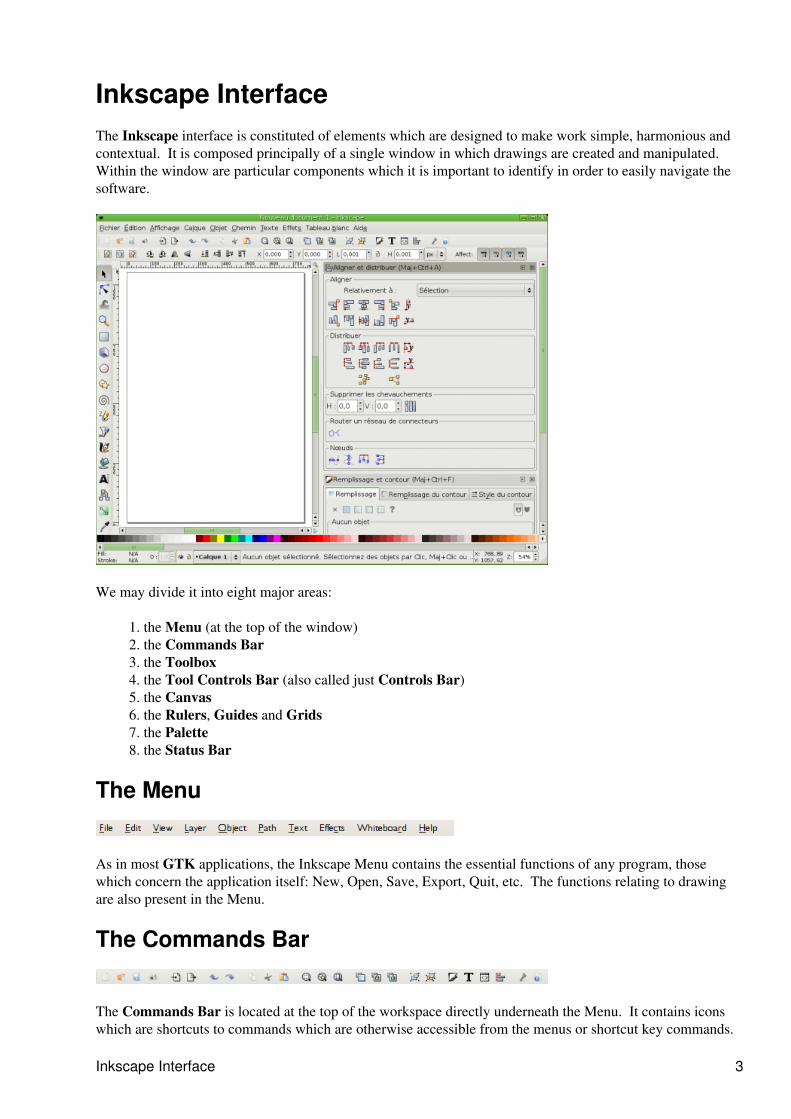
Inkscape InterfaceThe Inkscape interface is constituted of elements which are designed to make work simple, harmonious andcontextual. It is composed principally of a single window in which drawings are created and manipulated. Within the window are particular components which it is important to identify in order to easily navigate thesoftware.
We may divide it into eight major areas:
the Menu (at the top of the window)1. the Commands Bar2. the Toolbox3. the Tool Controls Bar (also called just Controls Bar)4. the Canvas5. the Rulers, Guides and Grids6. the Palette7. the Status Bar 8.
The Menu
As in most GTK applications, the Inkscape Menu contains the essential functions of any program, thosewhich concern the application itself: New, Open, Save, Export, Quit, etc. The functions relating to drawingare also present in the Menu.
The Commands Bar
The Commands Bar is located at the top of the workspace directly underneath the Menu. It contains iconswhich are shortcuts to commands which are otherwise accessible from the menus or shortcut key commands.
Inkscape Interface 3
It also contains other controls for manipulating the document and drawing objects. For example, from theCommands Bar you can open a new or existing document, print, import an image, undo previous commands,zoom, open the dialog to adjust document properties, etc. It is possible to see all the functions by hoveringover each one and reading the tooltips.
There may be an arrow on the right side of the Commands Bar pointing down which you can click to revealany command shortcuts that were not able to fit on the bar due to monitor size or resolution settings.
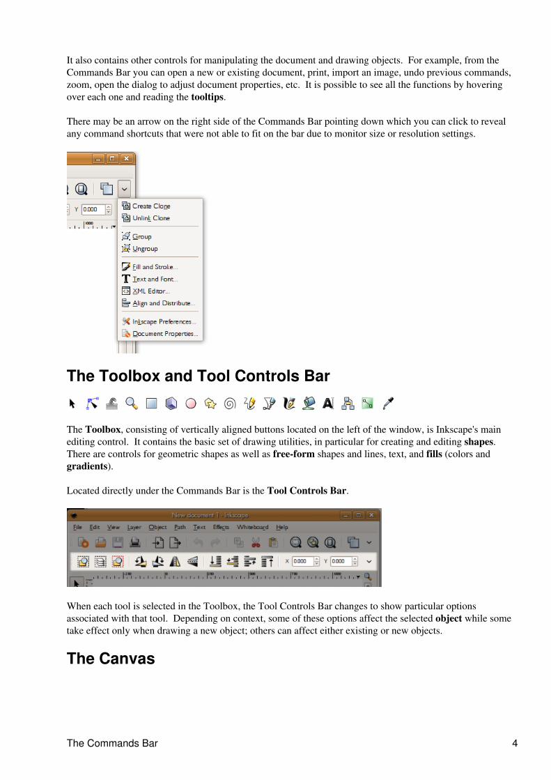
The Toolbox and Tool Controls Bar
The Toolbox, consisting of vertically aligned buttons located on the left of the window, is Inkscape's mainediting control. It contains the basic set of drawing utilities, in particular for creating and editing shapes. There are controls for geometric shapes as well as free-form shapes and lines, text, and fills (colors andgradients).
Located directly under the Commands Bar is the Tool Controls Bar.
When each tool is selected in the Toolbox, the Tool Controls Bar changes to show particular optionsassociated with that tool. Depending on context, some of these options affect the selected object while sometake effect only when drawing a new object; others can affect either existing or new objects.
The Canvas
The Commands Bar 4
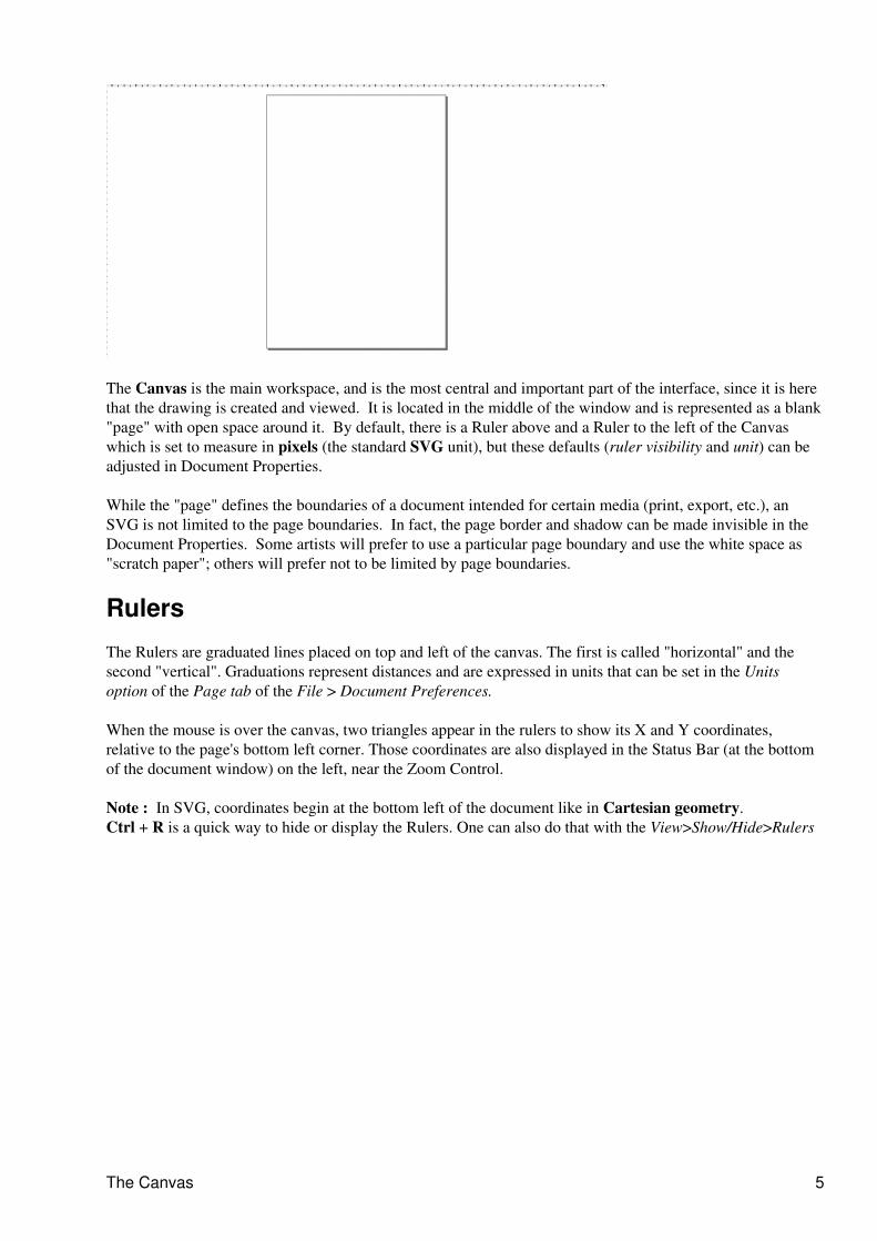
The Canvas is the main workspace, and is the most central and important part of the interface, since it is herethat the drawing is created and viewed. It is located in the middle of the window and is represented as a blank"page" with open space around it. By default, there is a Ruler above and a Ruler to the left of the Canvaswhich is set to measure in pixels (the standard SVG unit), but these defaults (ruler visibility and unit) can beadjusted in Document Properties.
While the "page" defines the boundaries of a document intended for certain media (print, export, etc.), anSVG is not limited to the page boundaries. In fact, the page border and shadow can be made invisible in theDocument Properties. Some artists will prefer to use a particular page boundary and use the white space as"scratch paper"; others will prefer not to be limited by page boundaries.
Rulers
The Rulers are graduated lines placed on top and left of the canvas. The first is called "horizontal" and thesecond "vertical". Graduations represent distances and are expressed in units that can be set in the Unitsoption of the Page tab of the File > Document Preferences.
When the mouse is over the canvas, two triangles appear in the rulers to show its X and Y coordinates,relative to the page's bottom left corner. Those coordinates are also displayed in the Status Bar (at the bottomof the document window) on the left, near the Zoom Control.
Note : In SVG, coordinates begin at the bottom left of the document like in Cartesian geometry.Ctrl + R is a quick way to hide or display the Rulers. One can also do that with the View>Show/Hide>Rulers
The Canvas 5
Guides
Guides are user-defined 'magnetic' lines. Using Guides makes object alignment easy even with the mouse. Touse Guides, click and drag from the Rulers to the point where the Guide is to be inserted and release. Clickingand dragging from the horizontal Ruler produces a horizontal Guide. Clicking and dragging from the verticalRuler produces a vertical Guide.
How to use
Moving Guides
When the Selector Tool F1 is active, passing the mouse over a Guide will change its color tored. Then, click and drag the Guide where you want.
Deleting guides
To delete a guide, just drag it to the appropriate Ruler with the Selector Tool F1
Guide Visibility
To make Guides invisible, without deleting them, select View > Guides from the Menu Bar.The keyboard shortcut for toggling Guide visibility is Shift | (hold shift and press the pipe - | -key, which is usually paired with the backslash key.)
File > Document properties let define if Guides should be displayed as default and change thecolor both of the Guide itself and for the highlight when the mouse passing over.
Rulers 6
Guides are also often used with snapping that makes it much more easier to place object onthe canvas, especially for precise or technical drawings. In this case just check the Snapguides while dragging checkbox.
Grids
Instead of using lots of Guides, it can be useful to activate Grids. Do this with the View > Grid menu or press# (Shift + 3 ).
There are of 2 types : rectangular and axonometric. They can be defined in the window from the DocumentProperties > File menu. Most commonly used is the rectangular Grid which is made of vertical and horizontallines.
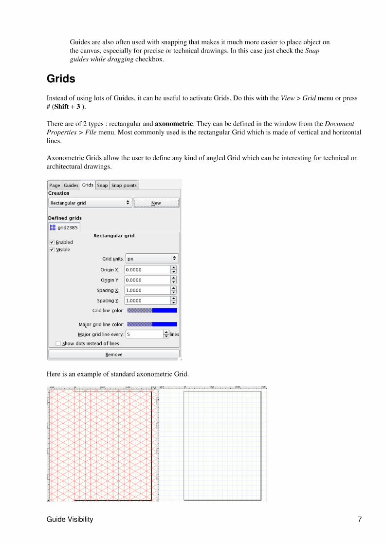
Axonometric Grids allow the user to define any kind of angled Grid which can be interesting for technical orarchitectural drawings.
Here is an example of standard axonometric Grid.
Guide Visibility 7
How to Use
To chose between one of those, just drop down the list in the document properties and click the new button. Anew tab is created within the main one (one can define several Grids for a single document). Then define theunits you would like to use and both the Origin point and the distance between to lines of the Grid. When onAxonometric Grids another option to define the angle is available.
Enabled
The user will use or not this Grid in the document
Visible
The user will see or not the grid on the canvas. This is the default value for that grid. But ifthe View > Grid is uncheck, the Grid won't be visible on the Canvas even if Visible is checkedhere.
Grid Units
Many commonly used units are available from mm, to feet and px. Choose the one that bestsuits your needs. If no special needs, keep the default px.
Origin X and Y
Define the beginning point of the Grid. Usually set to '0' (zero) it is useful to change if anoffset is needed especially to define margins from the Canvas side.
Spacing X and Y
Defines the space between to lines of the Grid. These spaces can be different for horizontaland vertical lines so that the Grid pattern can be set to any kind of rectangle.
Angle X and Y
Only available for axonometric Grids, lets define the angle of the Grid lines.
Grid line color
Default color for the Grid is blue, but this can be changed here. There are two kinds of line.The most often used is the Grid line, but the major Grid line helps to evaluate the distanceespecially when the grid spacing is short and that many lines are displayed. In this case, onecan define a different color for each, and set the frequency of major grid line , usually 5 or 10.
Show dots instead of lines
Since lines can overload the screen, it can be uneasy to work with Drawing Tools. It can bedone here.
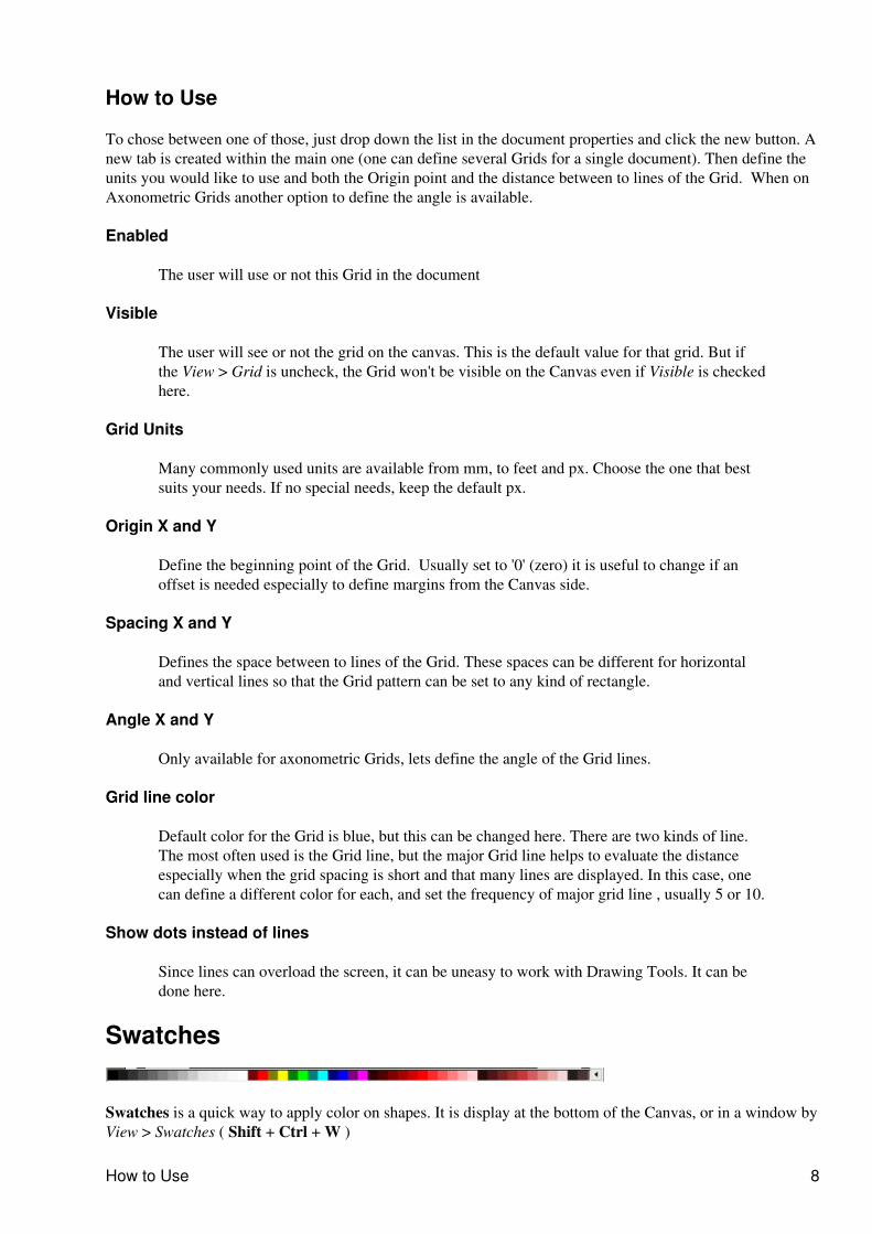
Swatches
Swatches is a quick way to apply color on shapes. It is display at the bottom of the Canvas, or in a window byView > Swatches ( Shift + Ctrl + W )
How to Use 8
How to Use
To find the color you like, just scroll the swatch line and choose. Yo can change the color by another preset byclicking the triangle at the right of the bar and choose one.
To apply a color in a shape as a fill color, just click on a color after selecting one or more shapes.
To apply the color on the stroke, press Shift while clicking and it's done.
Status Bar
Status Bar is the bottom-most of Inkscape interface. It includes (from left to right) :
Color indicator for the object• Quick layer selector• Help message area• Mouse Coordinate indicator• and finally a zoom factor in which one can right the factor he wants to use.•
How to Use 9
Working with files
Create a New Document
Document creation is an important step for working. This function allow access to a new blank page fordrawing. The File > New menu gives access to numerous predefined formats.
During new document creation, a new instance of the Inkscape window is opened with its own menu andown bars. There is no dialog that asks you to set the page properties. Instead the document defaultparameters are used. The default is a portrait A4 page, though this may be changed by creating a newdefault template.
Default settings are stored in a template in your directory share (on Linux, most often/usr/local/inkscape/share/templates). The template name Default.svg could be replacedby a customised file that contains your own options like size, border, zoom, metadata and so on...
Using
You can create a new file in several ways including:
By using the File Menu: File > New• By using the keyboard shortcut:Ctrl + N•
Additional Information
To change the document size after it's created, go to File > Document preferences.
Opening a Document
Instead of creating a new file you may wish to open an existing SVG document. This process can be usefulfor:
modifying an existing document;• getting some part of a document to reuse it for another one;• analysing the method used to create a picture, especially by viewing the code in the Inkscape XMLsource code editor;
•
exporting the document in a new format.•
Usage
This command can be called by several ways including:
By the File m=Menu: File->Open• By the keyboard shortcut: Ctrl + O•
Additional Information
Documents are always opened in a new window. This way, the work on newly opened documents istotally independent from concurrently open documents.
•
The closing of one document window does not close others.• It is possible to exchange objects from one document to another by copy/paste functions.•
Working with files 10
Warning : this menu allows optimum opening only for SVG documents. This operation doesn't modify thetype of the document. The opened formats are the same as the imported ones.
Saving files
As with document opening or creation, the saving of your file is an essential action, allowing you to finish theproduction later or to share the document with others.
Two functions are traditionally used for saving:
Save - modify existing document by saving changes. This operation should be done often, such aswhen the document reaches a new important step or is finished. Save modifies only the file it was lastsaved as.
•
Save as... save under a different file name. The save as method allows you to save several versions ofthe same document by changing the document name (by adding an incremental version number, forexample). Any new file should be immediately saved with this function to identify it.
•
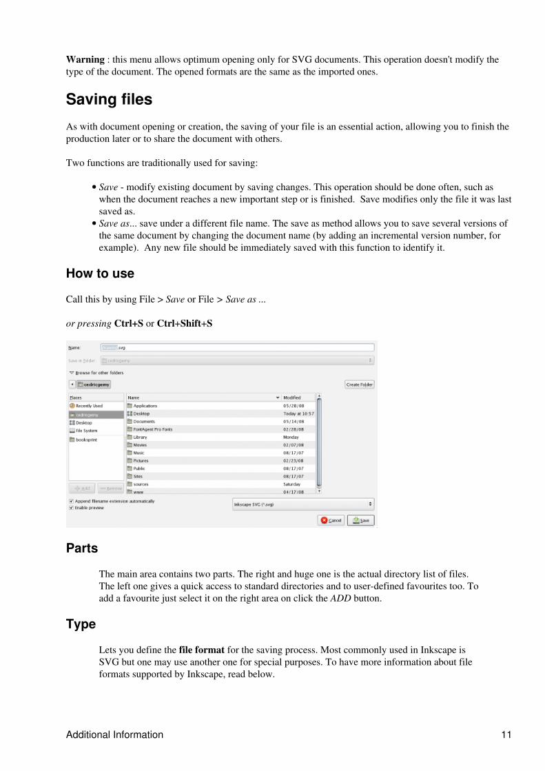
How to use
Call this by using File > Save or File > Save as ...
or pressing Ctrl+S or Ctrl+Shift+S
Parts
The main area contains two parts. The right and huge one is the actual directory list of files.The left one gives a quick access to standard directories and to user-defined favourites too. Toadd a favourite just select it on the right area on click the ADD button.
Type
Lets you define the file format for the saving process. Most commonly used in Inkscape isSVG but one may use another one for special purposes. To have more information about fileformats supported by Inkscape, read below.
Additional Information 11
Name
Just write the name of your new file here. You can add the extension (i.e. .svg, .pdf ...) so thatyou won't have to choose it the the format list.
Plain SVG is the most standard SVG. Use it if you don't know with what kind of SVG editorthe file will be read on. It's also the best for interoperability and export path to Gimp orBlender.
Inkscape SVG ( the default one) is to be considered as the most comprehensive as it keepsevery detail of your drawing, including Inkscape specific stuff like live shapes, layers... Thisformat may not be fully readable by other editors.
Formats
.svg (native Inkscape)
Inkscape default format, that keeps every shapes as easily editable aspossible.
.svg (plain)
SVG recommended format, fully compliant with W3C's spec. In this formatmany of the shapes (especially primitives) will be transformed to paths.
.svgz (compressed)
Compressed SVG with gzip compression. Low file size for quickerdownloading or uploading on the web.
Exchange format created by Adobe. Inkscape's PDF is 1.4 only, and needs tobe improved.
.svg (Adobe Illustrator 9+ , Adobe Illustrator)
Adobe Illustrator file format, with its specification. For those who have towork with proprietary software users.
.outline
text outline format
.xaml
eXtensible Application Markup Language, developed by Microsoft todefined Windows Vista Graphical Interface.
Name 12
.png
Raster image format recommended by W3C with alpha support.
.bmp
Raster image basic format. Produces very heavy pictures.
.wbmp
Wireless Bitmap format aimed for 2-bits (BW) encoding especially for earlymobile applications.
.ico, .cur
Microsoft Windows format for cursor and icons.
.jpg, .jpeg
Raster image format commonly used for photos on the internet. many camerado save pictures in JPEG format too.
.pnm, .pgm, .pbm, .ppm
Portable Anymap, Portable greymap, Portable bitmap, Portable Pixmap :Raster image format
.ras
Raster image format used by Sun Microsystems computers, typically createdon a Unix workstation; supports 1, 8, 24, and 32 bits per pixel; can beuncompressed or compressed using RLE compression; recognized by mostimage viewing programs.
.tiff
Raster image format especially made for professional printing process.
.xpm, .xbm
Raster image format used on X11 server for icons.
.tga, .targa
High level Raster image format frequently used in 3D-design for textures oralpha support.
.pcx
Old raster image format used mainly in the '80 and '90s. JPEG and PNG arenow recommended instead.
.png 13
.ps (Postscript), .eps (encapsulated postscript), .epsi(encapsulated postscript interchange)
Printers main language. Commonly used since early '80s to late '90s for rasterand vector mixing. Now mainly replaced by PDF.
.dia (dia)
Dia (software) editors diagrams
.ggr (Gimp Gradient)
GIMP gradient file format
.ani (animated)
Commonly used for animated cursors, especially on windows
.tex
LateX file format
.odg
Openoffice.org Draw (software), not fully compatible
.dxf
Standard format for technical drawings. Used to exchange with software asAutocad.
.pov
Pov ray file format for scripted 3D rendering.
.xcf
Gimp's file format file layer kept.
.ps (Postscript), .eps (encapsulated postscript), .epsi (encapsulated postscript interchange) 14
Selector ToolThe Selector Tool is used to select, position and transform objects on the Canvas with the mouse or otherinput device.
How to Use
Click once on an object with the Selector Tool to select it. The object will be framed with a bounding box (ablack, dashed line) and scale handles will appear. Click again on the same object and the scale handles willchange to rotation and skew handles. If the object is part of a group, the group will be selected, and draggingthe object handles will transform the group. Double-click an object with the Selector Tool and the tool willchange to the appropriate tool to edit the object (i.e., if you double-click an ellipse, the Ellipse Tool will beactivated, etc.).
Selecting Objects
Just click any object once to select it.
Adding Objects to and Removing Objects from Selection
Shift+Click objects to add them to the current selection or to remove them from the selection.
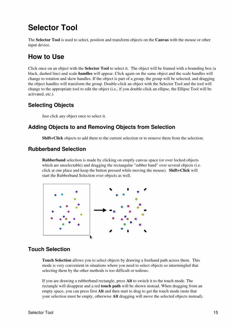
Rubberband Selection
Rubberband selection is made by clicking on emptly canvas space (or over locked objectswhich are unselectable) and dragging the rectangular "rubber band" over several objects (i.e.click at one place and keep the button pressed while moving the mouse). Shift+Click willstart the Rubberband Selection over objects as well.
Touch Selection
Touch Selection allows you to select objects by drawing a freehand path across them. Thismode is very convenient in situations where you need to select objects so intermingled thatselecting them by the other methods is too difficult or tedious.
If you are drawing a rubberband rectangle, press Alt to switch it to the touch mode. Therectangle will disappear and a red touch path will be shown instead. When dragging from anempty space, you can press first Alt and then start to drag to get the touch mode (note thatyour selection must be empty, otherwise Alt dragging will move the selected objects instead).
Selector Tool 15
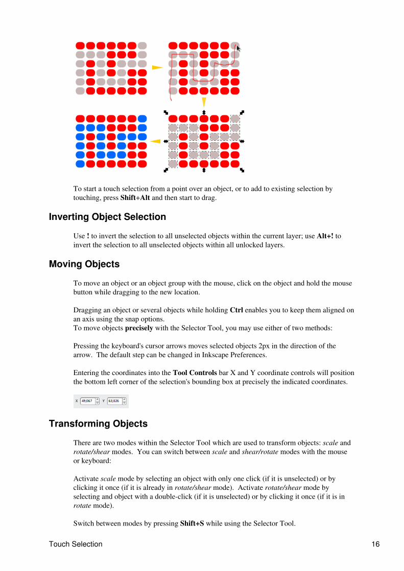
To start a touch selection from a point over an object, or to add to existing selection bytouching, press Shift+Alt and then start to drag.
Inverting Object Selection
Use ! to invert the selection to all unselected objects within the current layer; use Alt+! toinvert the selection to all unselected objects within all unlocked layers.
Moving Objects
To move an object or an object group with the mouse, click on the object and hold the mousebutton while dragging to the new location.
Dragging an object or several objects while holding Ctrl enables you to keep them aligned onan axis using the snap options.To move objects precisely with the Selector Tool, you may use either of two methods:
Pressing the keyboard's cursor arrows moves selected objects 2px in the direction of thearrow. The default step can be changed in Inkscape Preferences.
Entering the coordinates into the Tool Controls bar X and Y coordinate controls will positionthe bottom left corner of the selection's bounding box at precisely the indicated coordinates.
Transforming Objects
There are two modes within the Selector Tool which are used to transform objects: scale androtate/shear modes. You can switch between scale and shear/rotate modes with the mouseor keyboard:
Activate scale mode by selecting an object with only one click (if it is unselected) or byclicking it once (if it is already in rotate/shear mode). Activate rotate/shear mode byselecting and object with a double-click (if it is unselected) or by clicking it once (if it is inrotate mode).
Switch between modes by pressing Shift+S while using the Selector Tool.
Touch Selection 16
Scaling
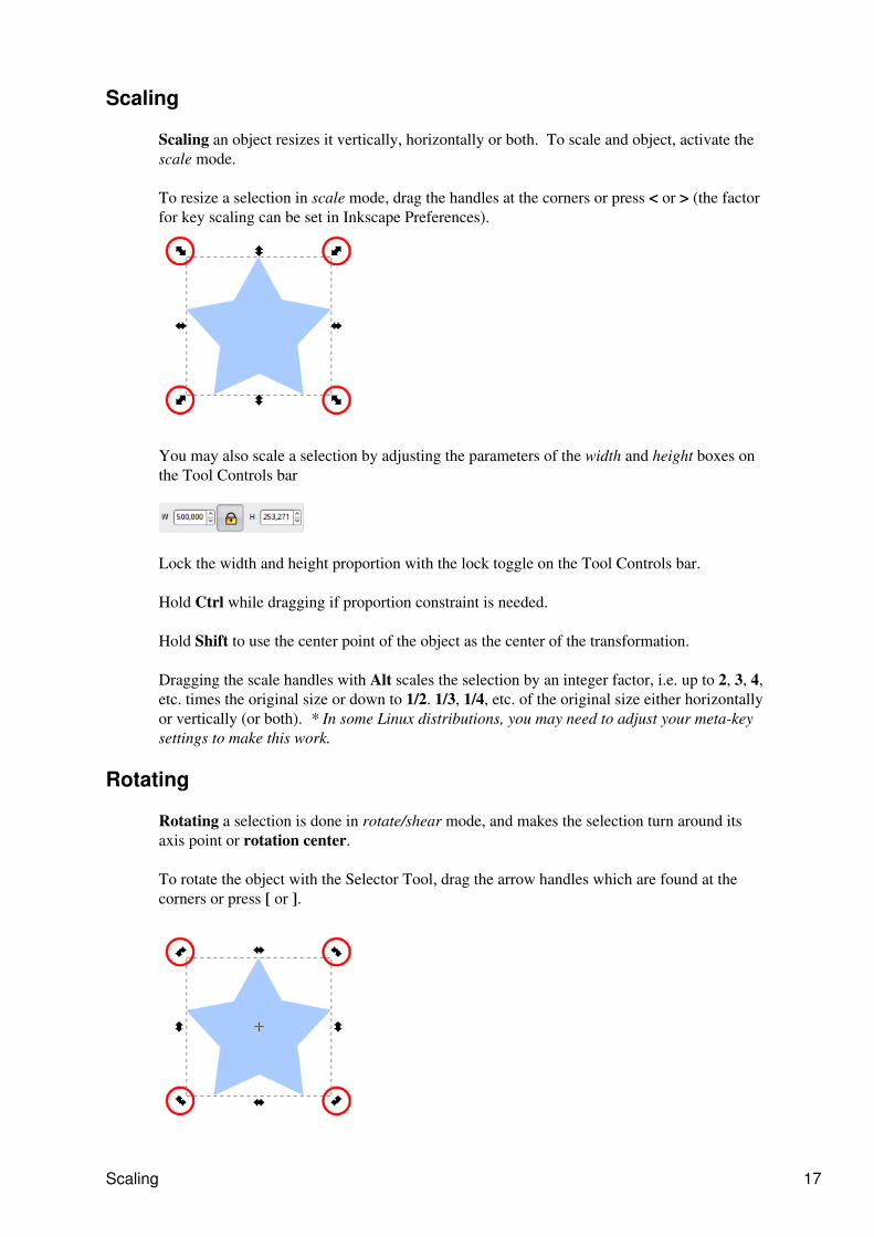
Scaling an object resizes it vertically, horizontally or both. To scale and object, activate thescale mode.
To resize a selection in scale mode, drag the handles at the corners or press < or > (the factorfor key scaling can be set in Inkscape Preferences).
You may also scale a selection by adjusting the parameters of the width and height boxes onthe Tool Controls bar
Lock the width and height proportion with the lock toggle on the Tool Controls bar.
Hold Ctrl while dragging if proportion constraint is needed.
Hold Shift to use the center point of the object as the center of the transformation.
Dragging the scale handles with Alt scales the selection by an integer factor, i.e. up to 2, 3, 4,etc. times the original size or down to 1/2. 1/3, 1/4, etc. of the original size either horizontallyor vertically (or both). * In some Linux distributions, you may need to adjust your meta-keysettings to make this work.
Rotating
Rotating a selection is done in rotate/shear mode, and makes the selection turn around itsaxis point or rotation center.
To rotate the object with the Selector Tool, drag the arrow handles which are found at thecorners or press [ or ].
Scaling 17
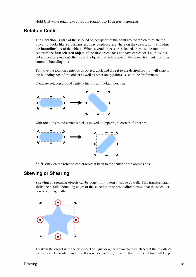
Hold Ctrl while rotating to constrain rotations to 15 degree increments.
Rotation Center
The Rotation Center of the selected object specifies the point around which to rotate theobject. It looks like a crosshairs and may be placed anywhere on the canvas, not just withinthe bounding box of the object. When several objects are selected, they use the rotationcenter of the first selected object. If the first object does not have center set (i.e. if it's in adefault central position), then several objects will rotate around the geometric center of theircommon bounding box
To move the rotation center of an object, click and drag it to the desired spot. It will snap tothe bounding box of the object as well as other snap points as set in the Preferences.
Compare rotation around center which is in it default position
with rotation around center which is moved to upper right corner of a shape:
Shift+click on the rotation center resets it back to the center of the object's box.
Skewing or Shearing
Skewing or shearing objects can be done in rotate/shear mode as well. This transformationshifts the parallel bounding edges of the selection in opposite directions so that the selectionis warped diagonally.
To skew the object with the Selector Tool, just drag the arrow handles placed at the middle ofeach sides. Horizontal handles will skew horizontally, meaning that horizontal line will keep
Rotating 18
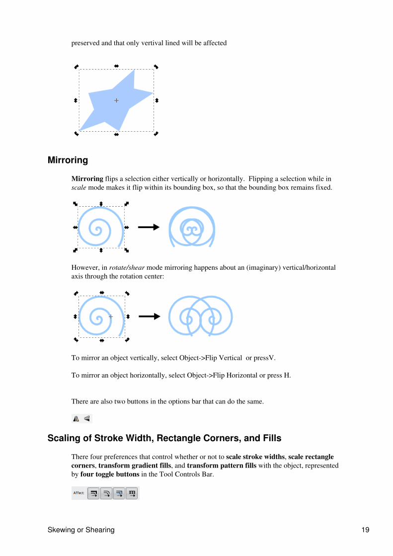
preserved and that only vertival lined will be affected
Mirroring
Mirroring flips a selection either vertically or horizontally. Flipping a selection while inscale mode makes it flip within its bounding box, so that the bounding box remains fixed.
However, in rotate/shear mode mirroring happens about an (imaginary) vertical/horizontalaxis through the rotation center:
To mirror an object vertically, select Object->Flip Vertical or pressV.
To mirror an object horizontally, select Object->Flip Horizontal or press H.
There are also two buttons in the options bar that can do the same.
Scaling of Stroke Width, Rectangle Corners, and Fills
There four preferences that control whether or not to scale stroke widths, scale rectanglecorners, transform gradient fills, and transform pattern fills with the object, representedby four toggle buttons in the Tool Controls Bar.
Skewing or Shearing 19

Tips
The Transform Window (Object->Transform or Shift+Ctrl+M) can be used for precisetransformations. Changes
1.
Press Esc to deselect, cancel selection, or cancels drag or transformation.2. Ctrl+Click or Shift+Ctrl+Click will select objects within groups from outside that group.3. Select Under: in Selector, Alt+click selects the object at cursor which is below (in z-order) thecurrently selected object at cursor; if the bottom object is reached, Alt+click again selects the topobject. Thus, several Alt+clicks will cycle selection through the z-order stack at the click point.Combining Alt with Ctrl ("select in groups") and Shift ("add to selection") works, too. Note that onLinux, many window managers steal Alt+click by default; reconfigure your WM so you can useAlt+click in Inkscape.
4.
Drag Selected: in Selector, Alt+Drag moves the currently selected object(s) no matter where youstart the drag, unlike regular drag that first selects the object under cursor. This is convenient fordragging objects that are behind other objects in z-order. On Linux, you may need to disable draggingthe window with Alt in your WM if you want to use "drag selected".
5.
Tips 20
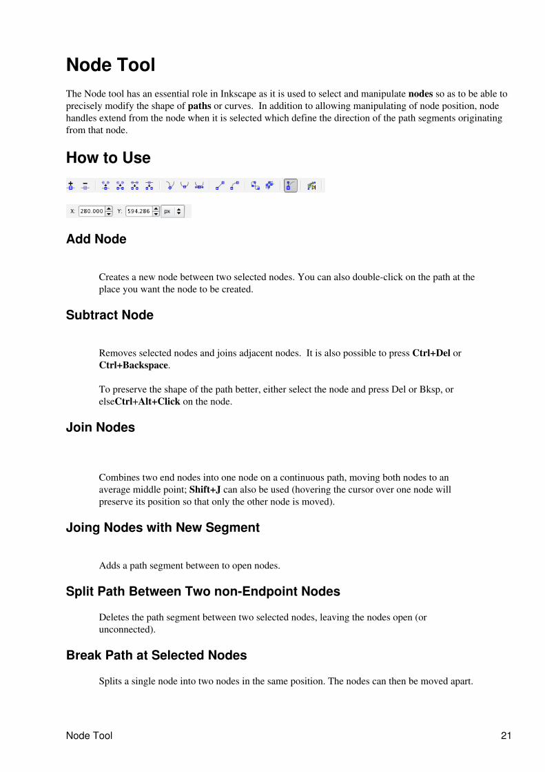
Node Tool The Node tool has an essential role in Inkscape as it is used to select and manipulate nodes so as to be able toprecisely modify the shape of paths or curves. In addition to allowing manipulating of node position, nodehandles extend from the node when it is selected which define the direction of the path segments originatingfrom that node.
How to Use
Add Node
Creates a new node between two selected nodes. You can also double-click on the path at theplace you want the node to be created.
Subtract Node
Removes selected nodes and joins adjacent nodes. It is also possible to press Ctrl+Del orCtrl+Backspace.
To preserve the shape of the path better, either select the node and press Del or Bksp, orelseCtrl+Alt+Click on the node.
Join Nodes
Combines two end nodes into one node on a continuous path, moving both nodes to anaverage middle point; Shift+J can also be used (hovering the cursor over one node willpreserve its position so that only the other node is moved).
Joing Nodes with New Segment
Adds a path segment between to open nodes.
Split Path Between Two non-Endpoint Nodes
Deletes the path segment between two selected nodes, leaving the nodes open (orunconnected).
Break Path at Selected Nodes
Splits a single node into two nodes in the same position. The nodes can then be moved apart.
Node Tool 21
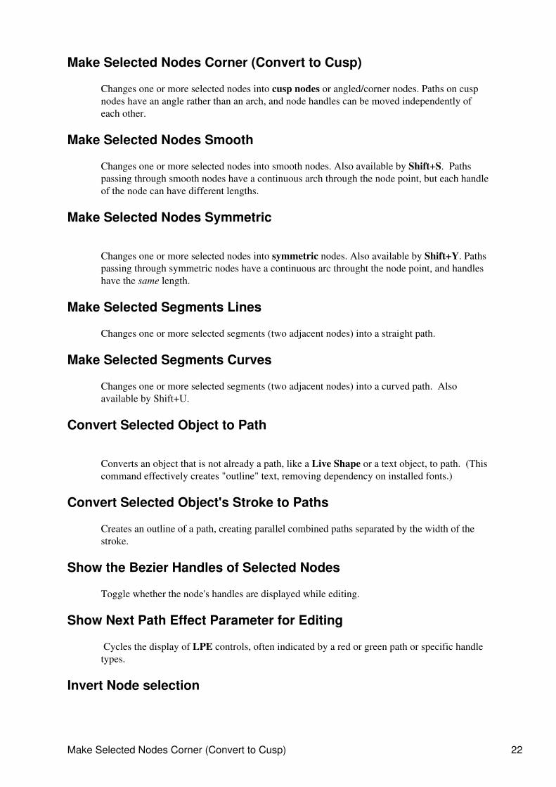
Make Selected Nodes Corner (Convert to Cusp)
Changes one or more selected nodes into cusp nodes or angled/corner nodes. Paths on cuspnodes have an angle rather than an arch, and node handles can be moved independently ofeach other.
Make Selected Nodes Smooth
Changes one or more selected nodes into smooth nodes. Also available by Shift+S. Pathspassing through smooth nodes have a continuous arch through the node point, but each handleof the node can have different lengths.
Make Selected Nodes Symmetric
Changes one or more selected nodes into symmetric nodes. Also available by Shift+Y. Pathspassing through symmetric nodes have a continuous arc throught the node point, and handleshave the same length.
Make Selected Segments Lines
Changes one or more selected segments (two adjacent nodes) into a straight path.
Make Selected Segments Curves
Changes one or more selected segments (two adjacent nodes) into a curved path. Alsoavailable by Shift+U.
Convert Selected Object to Path
Converts an object that is not already a path, like a Live Shape or a text object, to path. (Thiscommand effectively creates "outline" text, removing dependency on installed fonts.)
Convert Selected Object's Stroke to Paths
Creates an outline of a path, creating parallel combined paths separated by the width of thestroke.
Show the Bezier Handles of Selected Nodes
Toggle whether the node's handles are displayed while editing.
Show Next Path Effect Parameter for Editing
Cycles the display of LPE controls, often indicated by a red or green path or specific handletypes.
Invert Node selection
Make Selected Nodes Corner (Convert to Cusp) 22
The ! key inverts node selection in the current subpath(s) (i.e. subpaths with at least one selectednode); Alt ! inverts in the entire path. (This is similar to how these keys work in Selector, with currentsubpath(s) instead of the current layer.)
Hotkeys
Multiple select
Shift+Click to select several nodes in succession.
Near selection
Clicking on a selected path selects the two nodes closest to the click point (on either side).Shift+Click adds or removes these two nodes to the node selection (when only one path isselected; otherwise Shift+Click works as in Selector).
Adding nodes
Double-click or Shift+Alt+Click anywhere on the selected path (even if it is under otherobjects) creates a new node at the click point, without changing the shape of the path.
Tab selects the next nodeShift+Tab selects the previous node
Other
Rotate (direction of handles) by pressing [ or ] keys and scale (length of handles) by < or >keys. Ctrl+ any of these keys will affect only the left or right node handle (according towhether the left or right Ctrl key is pressed).
Rotating objects or control handles of a node with Ctrl restricts rotation to 15 degreeincrements. Dragging nodes may be restricted to horizontal/vertical with Ctrl and to thedirections of the node's handles (or there perpendiculars) with Ctrl+Alt. Dragging a node'scontrol points with Alt locks the length of the handle, and with Shift, rotates the other handleby the same angle. When several nodes are selected, pressing < or > scales, [ or ] rotates theselected nodes as if they were an �object�, around the center of that object. So, forexample, in a single-path silhouette portrait, you can select the nodes of the nose androtate/scale the nose as a whole without breaking the path into pieces. Pressing Alt with thesekeys gives pixel-sized movement depending on zoom, the same as in Selector. Also, you canpress h or v to flip the selected nodes horizontally or vertically.
Ctrl+click toggles cusp/smooth/symmetric, Ctrl+Alt+click deletes a node
Tips
When an object is selected handles appear making it possible to handle the shape of the object in anintuitive and precise way.
1.
You can switch the not-yet-finalized (red) segment of the path being drawn from curve to line (ShiftL) or back to curve (Shift U).
2.
Esc deselects, cancels selection, and cancels drag or transformation of any kind (so far only inselector and node edit). Arrows, Ctrl+a, and Tab / Shift+Tab act on nodes in node editor exactly asthey do on objects in Selector. The first Escape or empty-space click deselects any selected nodes,
3.
Hotkeys 23
the second one deselects the selected object removing the node display.The Node Tool selects objects regardless of grouping. This means you don't need to switch to selectorfor a Ctrl+click if you want to edit a grouped path.
4.
You can reverse the direction of selected path(s) either via Path > Reverse or by pressing 'r' in nodetool (useful for markers and combining paths).
5.
Ctrl+click on a node handle retracts that handle back to its node. 6. If a node does not show one or both handles (i.e. they are retracted), you can drag a handle out bydragging away from the node with Shift.
7.
Pressing Ctrl+A with some nodes selected will select not all nodes in the path but all nodes in thesubpath(s) containing the selected node(s). To select all nodes in the path unconditionally, eitherdeselect any nodes before pressing Ctrl+A, or use Select all in all subpaths (Ctrl+Alt+A) in Nodetool.
8.
Edit the selected path by dragging directly on the path.9. if you press Shift before starting to drag, you always get a node selection rubberband rectangle10. When you switch the type of the selected node to Smooth or Symmetric by pressing Shift+S /Shift+Y, you can now preserve the position of one of the two handles by hovering your mouse overit, so that only the other handle is rotated/scaled to match.
11.
You can grow or shrink node selection by hovering the mouse pointer over a node and usingmousewheel (up = grow, down = shrink) or the keys PageUp (grow) and PageDown (shrink).Growing adds the closest unselected node to the selection; shrinking deselects the farthest selectednode. There are two modes that differ by how the closest/farthest nodes are chosen:
12.
Spatial selection (mousewheel, PageUp / PageDown): distances to nodesare measured directly, regardless of which subpath a node belongs to.
◊
Linear selection (Ctrl+mousewheel, Ctrl+PageUp/Ctrl+PageDown): nodedistances are measured along the path, and only the nodes belonging to thesame subpath as the hovered node are considered (i.e. other subpaths arenever selected).
◊
This technique is convenient for quickly selecting an area in a complex path starting from a center -for example, for node sculpting.
13.
If any of the nodes in the currently selected path is mouseovered, then horizontal/vertical flipping ('H'and 'V' keys), stepwise rotation ('[' and ']' keys) and scaling ('<' and '>' keys) now all use this specificnode as center/axis. If there is no mouseovered node, the center of the bounding box is used instead(as is currently the case unconditionally). Nodes that are covered by one of their handles are alsodetected as mouseovered.
14.
Two entry fields are available on the Tool Controls bar which allow precise editing of the coordinatesof selected nodes.
15.
Tips 24
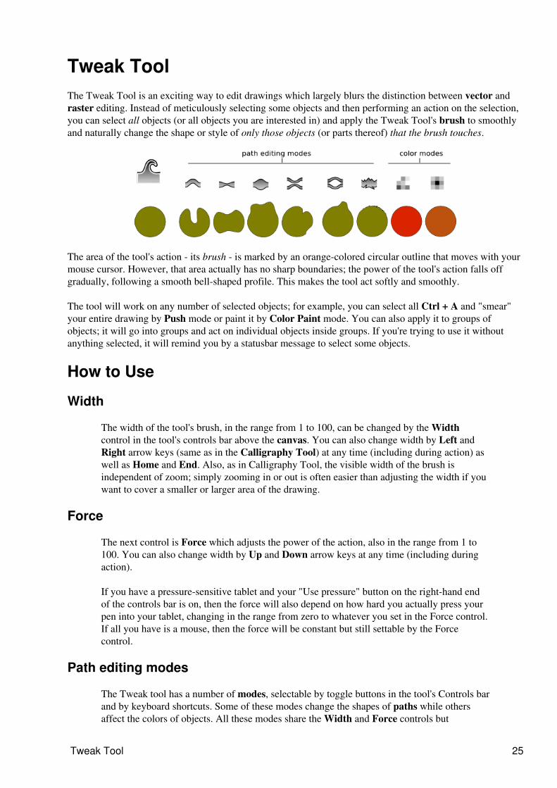
Tweak ToolThe Tweak Tool is an exciting way to edit drawings which largely blurs the distinction between vector andraster editing. Instead of meticulously selecting some objects and then performing an action on the selection,you can select all objects (or all objects you are interested in) and apply the Tweak Tool's brush to smoothlyand naturally change the shape or style of only those objects (or parts thereof) that the brush touches.
The area of the tool's action - its brush - is marked by an orange-colored circular outline that moves with yourmouse cursor. However, that area actually has no sharp boundaries; the power of the tool's action falls offgradually, following a smooth bell-shaped profile. This makes the tool act softly and smoothly.
The tool will work on any number of selected objects; for example, you can select all Ctrl + A and "smear"your entire drawing by Push mode or paint it by Color Paint mode. You can also apply it to groups ofobjects; it will go into groups and act on individual objects inside groups. If you're trying to use it withoutanything selected, it will remind you by a statusbar message to select some objects.
How to Use
Width
The width of the tool's brush, in the range from 1 to 100, can be changed by the Widthcontrol in the tool's controls bar above the canvas. You can also change width by Left andRight arrow keys (same as in the Calligraphy Tool) at any time (including during action) aswell as Home and End. Also, as in Calligraphy Tool, the visible width of the brush isindependent of zoom; simply zooming in or out is often easier than adjusting the width if youwant to cover a smaller or larger area of the drawing.
Force
The next control is Force which adjusts the power of the action, also in the range from 1 to100. You can also change width by Up and Down arrow keys at any time (including duringaction).
If you have a pressure-sensitive tablet and your "Use pressure" button on the right-hand endof the controls bar is on, then the force will also depend on how hard you actually press yourpen into your tablet, changing in the range from zero to whatever you set in the Force control.If all you have is a mouse, then the force will be constant but still settable by the Forcecontrol.
Path editing modes
The Tweak tool has a number of modes, selectable by toggle buttons in the tool's Controls barand by keyboard shortcuts. Some of these modes change the shapes of paths while othersaffect the colors of objects. All these modes share the Width and Force controls but
Tweak Tool 25
otherwise are quite different. Let's look at the path editing modes first.
Unlike the Node tool, to edit paths with the Tweak tool you don't need to worry about wherethe nodes of a path are and how to manipulate them. You just apply the tool's brush to anypoint, and the selected paths at that point will reshape smoothly and naturally - as if made ofsoft jelly - regardless of where its nodes lie. If applied to a shape or text object, the toolconverts them to paths automatically.
While not very useful for technical drawings, tweaking paths will be indispensable for artisticuses of Inkscape - cartoons, drawings, sketches, anime, etc. This new functionality issomewhat similar to the tools such as "Pucker" and "Bloat" in the latest versions of AdobeIllustrator.
There are currently six path editing modes in the Tweak Tool: Push, Shrink, Grow, Attract,Repel, and Roughen.
Push
This default mode of the tool, Push, Shift + P simply displaces the part of the path under thecursor in the direction of the drag. The path behaves like soft jelly, bending and bulgingsmoothly and naturally. It's an easy way to produce various irregular, lifelike,handmade-looking shapes starting from something as simple as an ellipse or a calligraphicstroke. For parallel-stroke hatching (engraving) done in the Calligraphy tool, pushing is aneasy way to bend, pinch, or curve the entire hatching uniformly.
Shrink and Grow
The Shrink ( Shift + S ) and Grow ( Shift + G ) are two opposite modes that move eachpoint of a path in a direction perpendicular to the path's surface at the point, either inwards(Shrink) or outwards (Grow). This is similar to the Inset and Outset commands, except thatthe Tweak Tool can act on a part of a path instead of the whole path.
For example, the visible lightness/darkness of an engraving hatching may not exactlycorrespond to your artistic intention. Also, the ends of Calligraphy pen strokes are often farfrom ideal - they may be too blunt or have unsightly bends or blobs. This is where the TweakTool may help. Select all the strokes in a hatching pattern and apply a light Shrink actionwhere you want the lines to become thinner (and the hatching to become lighter), up untiltotal disappearance. If you press hard, shrinking works as an eraser, so you can easily cleanthe strokes' ends to make them thin, sharp, and uniform. Conversely, applying Grow makesstrokes wider (i.e. the hatching becomes darker).
Of course, shrinking and growing are useful not only for calligraphic strokes. Same as withPush, with Shrink and Grow you can sculpt any path, spawning smooth treacle-likeappendages with Grow and carving holes with Shrink. Unlike the "node sculpting" mode inthe Node tool, however, this does not require adding new nodes to the shape.
Attract and Repel
The Attract ( Shift+ A )and Repel ( Shift + E ) modes work by moving each affected pointon a path towards (Attract) or from (Repel) the cursor point. In some cases this may looksimilar to Shrink and Grow, but the difference is that shrinking/growing moves pathsperpendicularly to the path in each point, whereas attracting/repelling moves them to or fromthe cursor regardless of the path shape. These modes are similar to the Pinch effect in AI; youcan use them for various central-symmetric distortions in parts of your paths.
Path editing modes 26
Roughen
The Roughen (Shift +R ) mode does exactly this: roughens the edge of the path withoutchanging its overall shape. Slight roughening simply makes the edge crooked and uneven;strong roughening tears and explodes the edge into random blobs and splotches. Note that thisoperation, especially with high Fidelity, adds a lot of nodes which increases the size of yourSVG document and may slow down Inkscape considerably. In particular, pushing, shrinking,or growing of a roughened path becomes much slower and more difficult, so it'srecommended to finalise the overall shape of a path first and roughen it, if necessary, only asthe final step.
Fidelity
Any tweaking of a path slightly distorts the entire path, including even those parts that youdidn't touch. These distortions are similar to those that a Simplify command produces. TheFidelity value (also in the range from 1 to 100, default is 50) allows you to control theamount of these distortions. With a higher fidelity, the distortions are less noticeable, but thepath may end up having a lot of nodes which inflates up the SVG size and slows downInkscape.
The best value of Fidelity depends on the nature of your artwork. If you're sculpting anamorphous blob, you can do with low fidelity of about 20. If, however, you are pushing orinflating a text string (as a single path) and want the letters outside the distorted area toremain crisp and clean, you will need to raise fidelity to 80 or more.
Color editing modes
The Color Paint ( Shift + C ) and Color Jitter ( Shift + J ) modes, unlike the path editingmodes, change the colors of objects instead of their shapes. Yet they share enough commonfeatures with the path editing modes to be part of the same tool: These modes also use acircular soft-edged brush controlled by the Width and Force parameters on the Controls barand affected by the pen pressure (if you have a pressure-sensitive tablet).
Color Paint applies the style of the tool to the selected objects under the brush. Thestyle of the tool is visible in the style swatch at the rightmost end of the tool's controlbar; it can be changed by clicking on the color palette or by any other styleassignment command, such as Fill and Stroke dialog. (Note: unlike all other tools, inTweak tool in Color Paint mode you cannot assign style directly to selected objects;any style-setting command changes the tool's style instead.)
♦
The fill from the tool's style applies to the fills of the painted objects, and the strokeapplies to the strokes. If the tool's style has no fill or no stroke, it won't affect fills orstrokes, correspondingly. For example, if you want to color the fills of objects bluebut leave their strokes untouched, assign blue fill to the tool's style (just click blue onthe palette) but set its stroke to None (middle-click the Stroke swatch in thestatusbar). Similarly, master opacity in the tool's style affects master opacities of thetouched objects (if the O channel is on, see below).This mode allows you to literally paint over objects, shifting their colors towards thetarget style of the tool. For example, if you paint with yellow fill over a blue-filledobject, the object will become greenish blue, then green, then yellowish green, andend up being exactly the yellow color you're painting with. This speed of this gradualtransition depends on both Force parameter and pen pressure; also, objects touchedby the periphery of the brush are less affected than those hit by the brush centre.Overall, using this tool is very similar to a soft brush in a raster editor such as Gimpor Photoshop.
Roughen 27
Color Jitter mode does not apply any color, but instead jitters (randomises) thecolors of the objects it touches. The force of the action determines how strong is therandomisation, i.e. how far the colors deviate from the original values. This modedoes not use the tool's style.
♦
Both modes work on flat fills and gradients; for gradients, the tool takes into account not onlythe position of the entire object with gradient, but also the position of each gradient stoprelative to the brush. This means that, for example, you can change the blue color only in anobject filled with blue-red gradient simply by painting over its blue end with a brush smallenough to not touch the red. (Note that color tweaking does not create gradients on objectsthat used flat color before, but only adjusts existing gradients in the drawing.)
Channels
Color Paint and Color Jitter honor the Channels control. This control comprises the fourbuttons: H, S, L, and O, which allow you to turn on and off the tool's action on the object'shue, saturation, lightness, and opacity, correspondingly. For example, if you want to raise thesaturation of some part of your drawing without changing the hue, select somemaximum-saturation color (e.g. pure red) and turn off all Channels buttons except S.Similarly, you can replace the hues without affecting saturation or lightness (only H pressed),or lighten/darken all colors without changing their hues and saturation (only L pressed).Pressing O allows you to apply the master opacity from the tool's style to the master opacityof objects (but not fill or stroke opacity).
Usage notes
Color painting with Tweak tool is similar, but not exactly analogous to bitmap painting. Eventhough the tool itself works as a soft brush, it still applies its color to vector objects, whichbehave as vector objects usually do. For example, if you want to change the tint of the face inyour drawing, and if a hand in the drawing is part of the same object as the face, that handwill change its tint too even if it's located far from the point you are painting. (We foresee a"fracture" command in one of the next versions of Inkscape which will help you turn amonolithic object into a mosaic of small fragments that will be then easy to paint with Tweaktool.) Still, even with this limitation, color painting is a novel way of dealing with vectordrawings which allows you to quickly and intuitively make adjustments which would beawkward and slow with traditional approach.
Drawings containing patterns or scatterings of small independent objects are best suited forcolor painting with Tweak tool. Examples include:
freehand drawings with Calligraphy pen, consisting of many separate strokes;♦ gradient meshes imported from Adobe Illustrator files (Inkscape renders these meshesas lattices of small polygons; while there's no direct support for gradient meshes inInkscape yet, color painting on such lattices is almost as good);
♦
text converted to paths and with Break Apart command applied so that each letter is aseparate path;
♦
patterns made with the Tile Clones command; note that you need to unset the filland/or stroke on the original object and use the Color tab to assign some initial colorto the clones - this will make them paintable with the Tweak tool without unlinking.
♦
Moreover, color tweaking can be useful for compositions with a few objects or even forsingle objects. Unlike all other color selection methods, painting with the Tweak toolimplements the color mixing metaphor which is much more familiar to traditional artists thanRGB sliders or even the color wheel. For example, start with a rectangle of pure blue color;then, pick different colors by Color Paint and apply light touches with minimum Force andminimum pen pressure: add a little green, a little brown, a little yellow, etc. until you have the
Color editing modes 28
exact hue you need. Similarly, you can whiten or blacken any hue by admixing white orblack.
You can also use color tweaking to add a tint, darken/lighten, saturate/desaturate, or colorjitter your entire drawing. Just select all in all layers, zoom out, choose a large brush width soit covers all of the drawing, and apply a little color tweaking (with minimum Force) that willtherefore affect all visible objects.
Hotkeys
W, Shift + F2: switch to the Tweak Tool•
Shift +P: switch to the Push mode•
Shift+S: switch to the Shrink mode•
Shift+G: switch to the Grow mode•
Shift+A: switch to the Attract mode•
Shift+E: switch to the Repel mode•
Shift+R: switch to the Roughen mode•
Shift+C: switch to the Color Paint mode•
Shift+J: switch to the Color Jitter mode•
Left, Right, Home, End: change width•
Up, Down: change force•
mouse drag: act on selected path in the current mode•
Ctrl+mouse drag: temporarily switch to Shrink (while Ctrl is down)•
Shift+Ctrl+mouse drag: temporarily switch to Grow (while Shift+Ctrl is down)•
Usage notes 29
Zoom ToolZoom Tool is a great way to navigate on the canvas. It can be accessed via several ways that are verycompletementary and comfortable. Each zoom action is saved in a special history so that one can easily bezooming and unzooming without difficulties. All zooming operations via mouse preserve the point under thecursor (no centering).
How to use
Use this tool by:
clicking in the toolbox :•
pressing : F3
or : Ctrl Alt Mouse wheel
or : Shift Middle Mouse Button
•
Zooming
Zooming is just set the zoom factor to a higher level so that one can work more precisely.Pressing + does the same.
Unzoom
Unzooming can be used to have a larger view of the drawing or area. Pressing - can unzoomtoo.
Zoom to 1:1
Just displays the drawing at real pixel size. This way a banner drawing (for example) which is468 pixels wide, will be 468 pixels on screen. If the Inkscape window is smaller, some part ofthe drawing may be invisible.
Zoom to 1:2
Just displays the drawing at half the real pixel size. This way a Banner drawing which is 468pixels wide, will be 234 pixels on screen. If the Inkscape window is smaller, some part of thedrawing may be invisible.
Zoom to 2:1
Just displays the drawing at twice the real pixel size. This way a Banner drawing which is 468pixels wide, will be 936 pixels on screen. If the Inkscape window is smaller, some part of thedrawing may be invisible.
Adjust selection to window
The selecect area will fill the entire Inkscape window.
Zoom Tool 30
Adjust drawing to window
The existing current drawing will be displayed to fit the window size.
Adjust page to window
Best to have a complete overview of the page and work on a layout, makes the whole page fitthe window size depending on the orientation. Pressing 5 does the same action.
Adjust page width to window
Same as before except the whole page may not be displayed, especially if the page is portraitoriented. Gives a better result than previous with landscape drawing. Press 6 to activate itwith keyboard.
Previous zoom
Come back to the previous zoom factor, as saved in the zoom history. Inkscape now preservesthe history of zoom settings for each document. The ` key restores previous zoom; pressing `repeatedly will guide you through all the zoom settings you've used in this session. Shift + `moves forward in the zoom history.
Next zoom
Goes back to the next zoom factor, as saved in the zoom history, especially when previouszoom has jus be used.
Hotkeys
Shift is diminishing zoom factor.
Middle click zooms in, Shift + middle click zooms out (in addition to middle button + dragwhich pans canvas).
Tips
By default, rotating the mouse wheel scrolls the canvas vertically and Ctrl+wheel zooms in and out.Now, if you turn on the Mouse wheel zooms by default checkbox in the Scrolling tab of the InksapePreferences dialog, this behavior is reversed: mouse wheel zooms without Ctrl and scrolls with Ctrl.This new mode should be familiar for users of AutoCAD and CorelDraw.
1.
Now you can use Shift+middle button drag, in any tool, to zoom into an area. This works the sameas simple drag in Zoom tool, but is faster because it does not require switching away from yourcurrent tool. Together with middle button drag (panning), middle button click (zoom in) andShift+middle button click (zoom out), this completes the set of canvas navigation shortcuts availablein any tool or context.
2.
In the Zoom tool, right mouse button always zooms out instead of calling the context menu3.
Adjust drawing to window 31
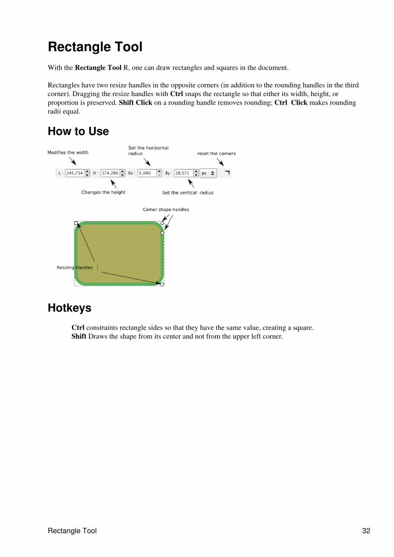
Rectangle ToolWith the Rectangle Tool R, one can draw rectangles and squares in the document.
Rectangles have two resize handles in the opposite corners (in addition to the rounding handles in the thirdcorner). Dragging the resize handles with Ctrl snaps the rectangle so that either its width, height, orproportion is preserved. Shift Click on a rounding handle removes rounding; Ctrl Click makes roundingradii equal.
How to Use
Hotkeys
Ctrl constraints rectangle sides so that they have the same value, creating a square.Shift Draws the shape from its center and not from the upper left corner.
Rectangle Tool 32
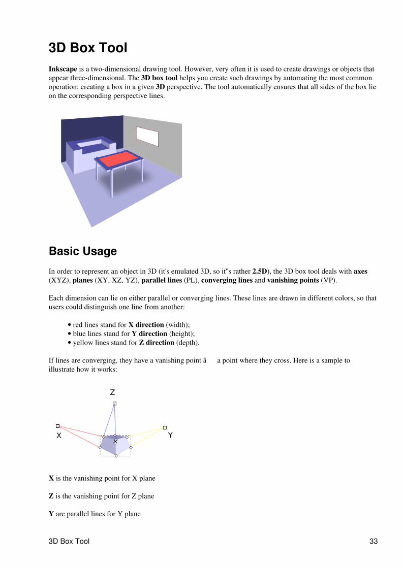
3D Box ToolInkscape is a two-dimensional drawing tool. However, very often it is used to create drawings or objects thatappear three-dimensional. The 3D box tool helps you create such drawings by automating the most commonoperation: creating a box in a given 3D perspective. The tool automatically ensures that all sides of the box lieon the corresponding perspective lines.
Basic Usage
In order to represent an object in 3D (it's emulated 3D, so it''s rather 2.5D), the 3D box tool deals with axes(XYZ), planes (XY, XZ, YZ), parallel lines (PL), converging lines and vanishing points (VP).
Each dimension can lie on either parallel or converging lines. These lines are drawn in different colors, so thatusers could distinguish one line from another:
red lines stand for X direction (width);• blue lines stand for Y direction (height);• yellow lines stand for Z direction (depth).•
If lines are converging, they have a vanishing point � a point where they cross. Here is a sample toillustrate how it works:
X is the vanishing point for X plane
Z is the vanishing point for Z plane
Y are parallel lines for Y plane
3D Box Tool 33
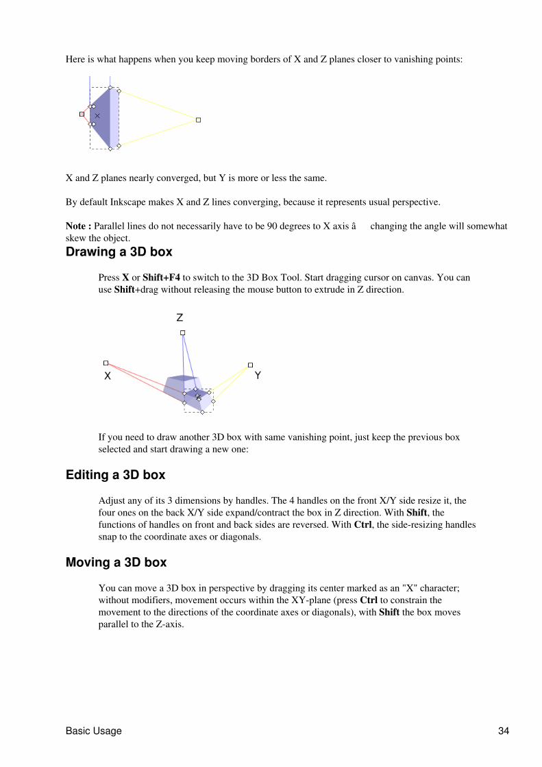
Here is what happens when you keep moving borders of X and Z planes closer to vanishing points:
X and Z planes nearly converged, but Y is more or less the same.
By default Inkscape makes X and Z lines converging, because it represents usual perspective.
Note : Parallel lines do not necessarily have to be 90 degrees to X axis � changing the angle will somewhatskew the object.Drawing a 3D box
Press X or Shift+F4 to switch to the 3D Box Tool. Start dragging cursor on canvas. You canuse Shift+drag without releasing the mouse button to extrude in Z direction.
If you need to draw another 3D box with same vanishing point, just keep the previous boxselected and start drawing a new one:
Editing a 3D box
Adjust any of its 3 dimensions by handles. The 4 handles on the front X/Y side resize it, thefour ones on the back X/Y side expand/contract the box in Z direction. With Shift, thefunctions of handles on front and back sides are reversed. With Ctrl, the side-resizing handlessnap to the coordinate axes or diagonals.
Moving a 3D box
You can move a 3D box in perspective by dragging its center marked as an "X" character;without modifiers, movement occurs within the XY-plane (press Ctrl to constrain themovement to the directions of the coordinate axes or diagonals), with Shift the box movesparallel to the Z-axis.
Basic Usage 34
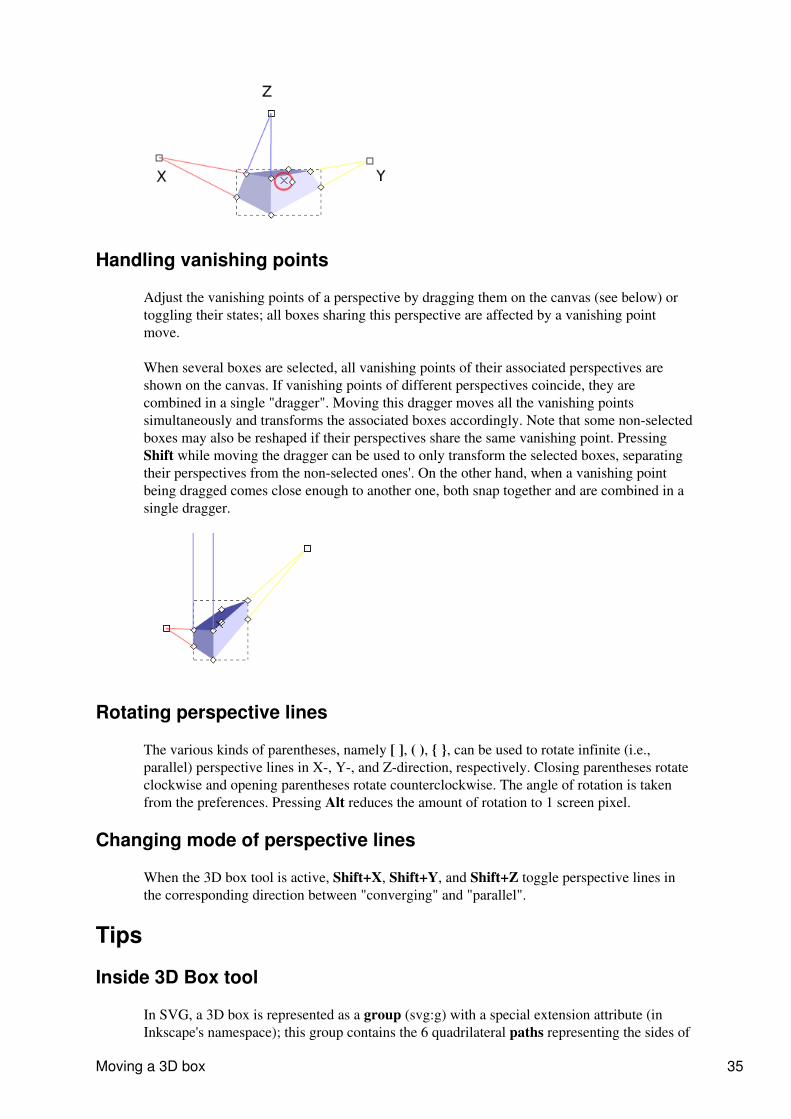
Handling vanishing points
Adjust the vanishing points of a perspective by dragging them on the canvas (see below) ortoggling their states; all boxes sharing this perspective are affected by a vanishing pointmove.
When several boxes are selected, all vanishing points of their associated perspectives areshown on the canvas. If vanishing points of different perspectives coincide, they arecombined in a single "dragger". Moving this dragger moves all the vanishing pointssimultaneously and transforms the associated boxes accordingly. Note that some non-selectedboxes may also be reshaped if their perspectives share the same vanishing point. PressingShift while moving the dragger can be used to only transform the selected boxes, separatingtheir perspectives from the non-selected ones'. On the other hand, when a vanishing pointbeing dragged comes close enough to another one, both snap together and are combined in asingle dragger.
Rotating perspective lines
The various kinds of parentheses, namely [ ], ( ), { }, can be used to rotate infinite (i.e.,parallel) perspective lines in X-, Y-, and Z-direction, respectively. Closing parentheses rotateclockwise and opening parentheses rotate counterclockwise. The angle of rotation is takenfrom the preferences. Pressing Alt reduces the amount of rotation to 1 screen pixel.
Changing mode of perspective lines
When the 3D box tool is active, Shift+X, Shift+Y, and Shift+Z toggle perspective lines inthe corresponding direction between "converging" and "parallel".
Tips
Inside 3D Box tool
In SVG, a 3D box is represented as a group (svg:g) with a special extension attribute (inInkscape's namespace); this group contains the 6 quadrilateral paths representing the sides of
Moving a 3D box 35

the box. Only the 3D box tool treats this object as a box; for all other tools it is just a group,so you can select any of the paths by Ctrl+click, apply any style to it, delete it, etc. You can ofcourse transform the entire box or any face in it using Selector or Node tools.
Inside 3D Box tool 36
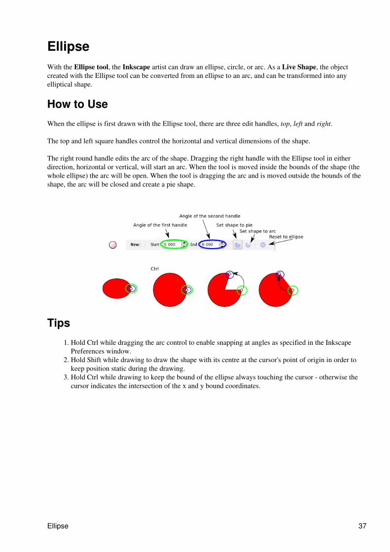
EllipseWith the Ellipse tool, the Inkscape artist can draw an ellipse, circle, or arc. As a Live Shape, the objectcreated with the Ellipse tool can be converted from an ellipse to an arc, and can be transformed into anyelliptical shape.
How to Use
When the ellipse is first drawn with the Ellipse tool, there are three edit handles, top, left and right.
The top and left square handles control the horizontal and vertical dimensions of the shape.
The right round handle edits the arc of the shape. Dragging the right handle with the Ellipse tool in eitherdirection, horizontal or vertical, will start an arc. When the tool is moved inside the bounds of the shape (thewhole ellipse) the arc will be open. When the tool is dragging the arc and is moved outside the bounds of theshape, the arc will be closed and create a pie shape.
Tips
Hold Ctrl while dragging the arc control to enable snapping at angles as specified in the InkscapePreferences window.
1.
Hold Shift while drawing to draw the shape with its centre at the cursor's point of origin in order tokeep position static during the drawing.
2.
Hold Ctrl while drawing to keep the bound of the ellipse always touching the cursor - otherwise thecursor indicates the intersection of the x and y bound coordinates.
3.
Ellipse 37
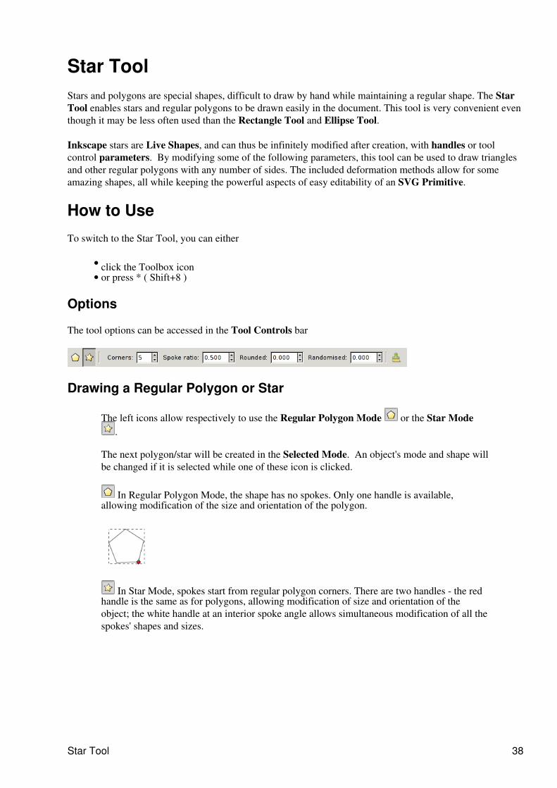
Star ToolStars and polygons are special shapes, difficult to draw by hand while maintaining a regular shape. The StarTool enables stars and regular polygons to be drawn easily in the document. This tool is very convenient eventhough it may be less often used than the Rectangle Tool and Ellipse Tool.
Inkscape stars are Live Shapes, and can thus be infinitely modified after creation, with handles or toolcontrol parameters. By modifying some of the following parameters, this tool can be used to draw trianglesand other regular polygons with any number of sides. The included deformation methods allow for someamazing shapes, all while keeping the powerful aspects of easy editability of an SVG Primitive.
How to Use
To switch to the Star Tool, you can either
click the Toolbox icon • or press * ( Shift+8 )•
Options
The tool options can be accessed in the Tool Controls bar
Drawing a Regular Polygon or Star
The left icons allow respectively to use the Regular Polygon Mode or the Star Mode.
The next polygon/star will be created in the Selected Mode. An object's mode and shape willbe changed if it is selected while one of these icon is clicked.
In Regular Polygon Mode, the shape has no spokes. Only one handle is available,allowing modification of the size and orientation of the polygon.
In Star Mode, spokes start from regular polygon corners. There are two handles - the redhandle is the same as for polygons, allowing modification of size and orientation of theobject; the white handle at an interior spoke angle allows simultaneous modification of all thespokes' shapes and sizes.
Star Tool 38
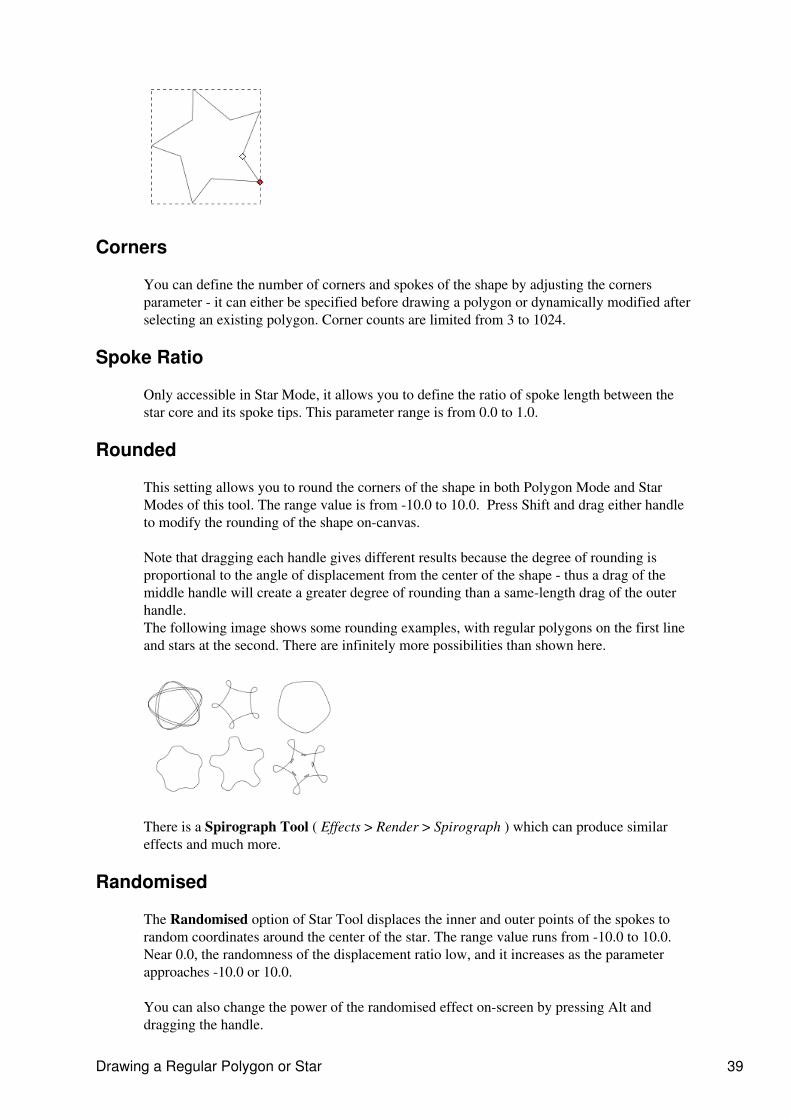
Corners
You can define the number of corners and spokes of the shape by adjusting the cornersparameter - it can either be specified before drawing a polygon or dynamically modified afterselecting an existing polygon. Corner counts are limited from 3 to 1024.
Spoke Ratio
Only accessible in Star Mode, it allows you to define the ratio of spoke length between thestar core and its spoke tips. This parameter range is from 0.0 to 1.0.
Rounded
This setting allows you to round the corners of the shape in both Polygon Mode and StarModes of this tool. The range value is from -10.0 to 10.0. Press Shift and drag either handleto modify the rounding of the shape on-canvas.
Note that dragging each handle gives different results because the degree of rounding isproportional to the angle of displacement from the center of the shape - thus a drag of themiddle handle will create a greater degree of rounding than a same-length drag of the outerhandle.The following image shows some rounding examples, with regular polygons on the first lineand stars at the second. There are infinitely more possibilities than shown here.
There is a Spirograph Tool ( Effects > Render > Spirograph ) which can produce similareffects and much more.
Randomised
The Randomised option of Star Tool displaces the inner and outer points of the spokes torandom coordinates around the center of the star. The range value runs from -10.0 to 10.0.Near 0.0, the randomness of the displacement ratio low, and it increases as the parameterapproaches -10.0 or 10.0.
You can also change the power of the randomised effect on-screen by pressing Alt anddragging the handle.
Drawing a Regular Polygon or Star 39

Default
Reset shape parameters to defaults.
Additional information
Polygons are always drawn with their geometric centers at the cursor origin - this cannot bechanged
Ctrl - Constrain the star shape to follow some angles. The cursor move allow to modify angleby regular increment. The increment value can be defined in the general preferences window:File > Inkscape Preferences... > Steps tab.
Default 40
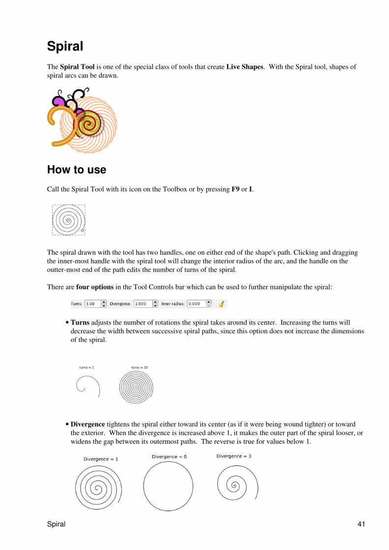
SpiralThe Spiral Tool is one of the special class of tools that create Live Shapes. With the Spiral tool, shapes ofspiral arcs can be drawn.
How to use
Call the Spiral Tool with its icon on the Toolbox or by pressing F9 or I.
The spiral drawn with the tool has two handles, one on either end of the shape's path. Clicking and draggingthe inner-most handle with the spiral tool will change the interior radius of the arc, and the handle on theoutter-most end of the path edits the number of turns of the spiral.
There are four options in the Tool Controls bar which can be used to further manipulate the spiral:
Turns adjusts the number of rotations the spiral takes around its center. Increasing the turns willdecrease the width between successive spiral paths, since this option does not increase the dimensionsof the spiral.
•
Divergence tightens the spiral either toward its center (as if it were being wound tighter) or towardthe exterior. When the divergence is increased above 1, it makes the outer part of the spiral looser, orwidens the gap between its outermost paths. The reverse is true for values below 1.
•
Spiral 41
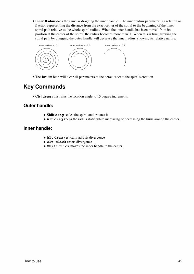
Inner Radius does the same as dragging the inner handle. The inner radius parameter is a relation orfraction representing the distance from the exact center of the spiral to the beginning of the innerspiral path relative to the whole spiral radius. When the inner handle has been moved from itsposition at the center of the spiral, the radius becomes more than 0. When this is true, growing thespiral path by dragging the outer handle will decrease the inner radius, showing its relative nature.
•
The Broom icon will clear all parameters to the defaults set at the spiral's creation.•
Key Commands
Ctrl drag constrains the rotation angle to 15 degree increments•
Outer handle:
Shift drag scales the spiral and ;rotates it♦ Alt drag keeps the radius static while increasing or decreasing the turns around the center♦
Inner handle:
Alt drag vertically adjusts divergence♦ Alt click resets divergence♦ Shift click moves the inner handle to the center♦
How to use 42
Pencil ToolWith the Pencil Tool ( P or F6 ), the Inkscape artist creates freehand paths by drawing directly on the canvasin the desired curves. Inkscape evaluates the line or shape drawn by the user and produces nodes to form thepath. After the path is drawn, the nodes of the path can be edited with the Node Tool, like other paths.
How to use
Choose the Pencil Tool and just click and drag the mouse to draw the line. By default it has no fill, but thiscan be set by any means (swatch or Fill and Stroke dialog). The line can also be set with stroke properties andcolors in the Fill and Stroke dialog.
It is possible to close the line drawn while returning towards the initial point. When the mouse is close to thispoint, the point changes color to red to specify that a release of the mouse at this moment closes the shape.
Tips
These tools can create single dots by Ctrl + click on the canvas. This creates a small circle filled with thecurrent stroke color. The radius can be set in the Preferences of the respective tools (it is specified as amultiple of the current stroke width). Shift + Ctrl + click creates a dot twice the specified size, and Alt + Ctrl+ click varies the size of the created dots randomly.
Pencil Tool 43
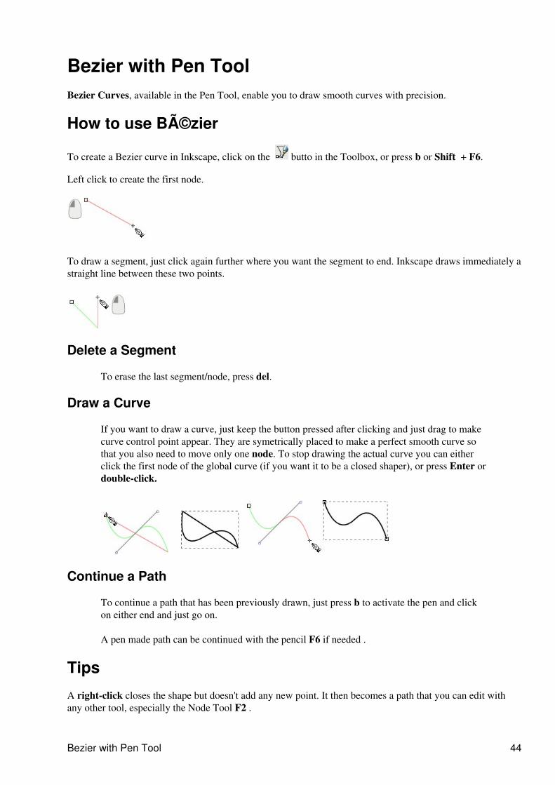
Bezier with Pen ToolBezier Curves, available in the Pen Tool, enable you to draw smooth curves with precision.
How to use Bézier
To create a Bezier curve in Inkscape, click on the butto in the Toolbox, or press b or Shift + F6.
Left click to create the first node.
To draw a segment, just click again further where you want the segment to end. Inkscape draws immediately astraight line between these two points.
Delete a Segment
To erase the last segment/node, press del.
Draw a Curve
If you want to draw a curve, just keep the button pressed after clicking and just drag to makecurve control point appear. They are symetrically placed to make a perfect smooth curve sothat you also need to move only one node. To stop drawing the actual curve you can eitherclick the first node of the global curve (if you want it to be a closed shaper), or press Enter ordouble-click.
Continue a Path
To continue a path that has been previously drawn, just press b to activate the pen and clickon either end and just go on.
A pen made path can be continued with the pencil F6 if needed .
Tips
A right-click closes the shape but doesn't add any new point. It then becomes a path that you can edit withany other tool, especially the Node Tool F2 .
Bezier with Pen Tool 44

Further editing of any curve can be accomplished with the Node Tool.
Tips 45
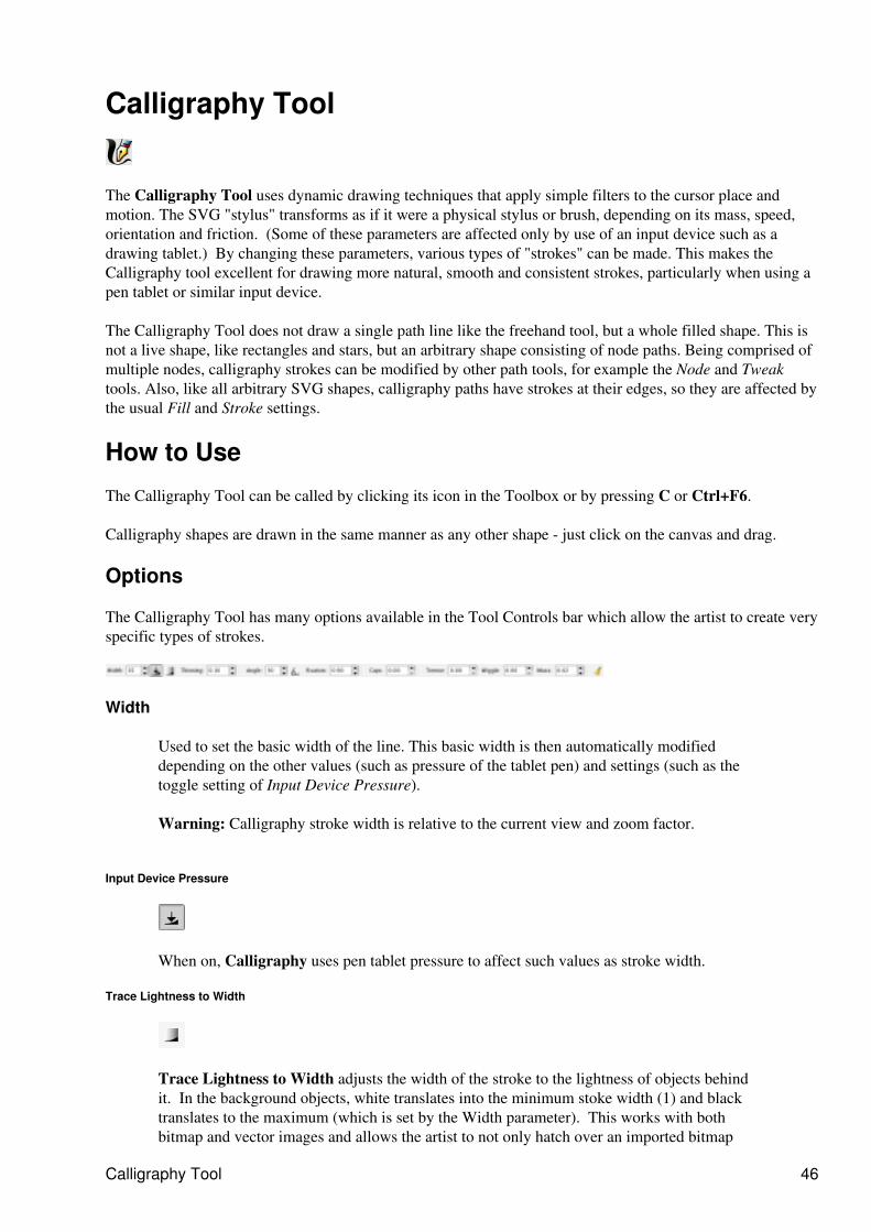
Calligraphy Tool
The Calligraphy Tool uses dynamic drawing techniques that apply simple filters to the cursor place andmotion. The SVG "stylus" transforms as if it were a physical stylus or brush, depending on its mass, speed,orientation and friction. (Some of these parameters are affected only by use of an input device such as adrawing tablet.) By changing these parameters, various types of "strokes" can be made. This makes theCalligraphy tool excellent for drawing more natural, smooth and consistent strokes, particularly when using apen tablet or similar input device.
The Calligraphy Tool does not draw a single path line like the freehand tool, but a whole filled shape. This isnot a live shape, like rectangles and stars, but an arbitrary shape consisting of node paths. Being comprised ofmultiple nodes, calligraphy strokes can be modified by other path tools, for example the Node and Tweaktools. Also, like all arbitrary SVG shapes, calligraphy paths have strokes at their edges, so they are affected bythe usual Fill and Stroke settings.
How to Use
The Calligraphy Tool can be called by clicking its icon in the Toolbox or by pressing C or Ctrl+F6.
Calligraphy shapes are drawn in the same manner as any other shape - just click on the canvas and drag.
Options
The Calligraphy Tool has many options available in the Tool Controls bar which allow the artist to create veryspecific types of strokes.
Width
Used to set the basic width of the line. This basic width is then automatically modifieddepending on the other values (such as pressure of the tablet pen) and settings (such as thetoggle setting of Input Device Pressure).
Warning: Calligraphy stroke width is relative to the current view and zoom factor.
Input Device Pressure
When on, Calligraphy uses pen tablet pressure to affect such values as stroke width.
Trace Lightness to Width
Trace Lightness to Width adjusts the width of the stroke to the lightness of objects behindit. In the background objects, white translates into the minimum stoke width (1) and blacktranslates to the maximum (which is set by the Width parameter). This works with bothbitmap and vector images and allows the artist to not only hatch over an imported bitmap
Calligraphy Tool 46
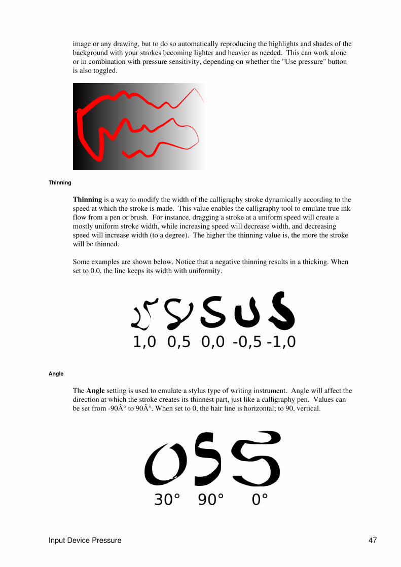
image or any drawing, but to do so automatically reproducing the highlights and shades of thebackground with your strokes becoming lighter and heavier as needed. This can work aloneor in combination with pressure sensitivity, depending on whether the "Use pressure" buttonis also toggled.
Thinning
Thinning is a way to modify the width of the calligraphy stroke dynamically according to thespeed at which the stroke is made. This value enables the calligraphy tool to emulate true inkflow from a pen or brush. For instance, dragging a stroke at a uniform speed will create amostly uniform stroke width, while increasing speed will decrease width, and decreasingspeed will increase width (to a degree). The higher the thinning value is, the more the strokewill be thinned.
Some examples are shown below. Notice that a negative thinning results in a thicking. Whenset to 0.0, the line keeps its width with uniformity.
Angle
The Angle setting is used to emulate a stylus type of writing instrument. Angle will affect thedirection at which the stroke creates its thinnest part, just like a calligraphy pen. Values canbe set from -90° to 90°. When set to 0, the hair line is horizontal; to 90, vertical.
Input Device Pressure 47
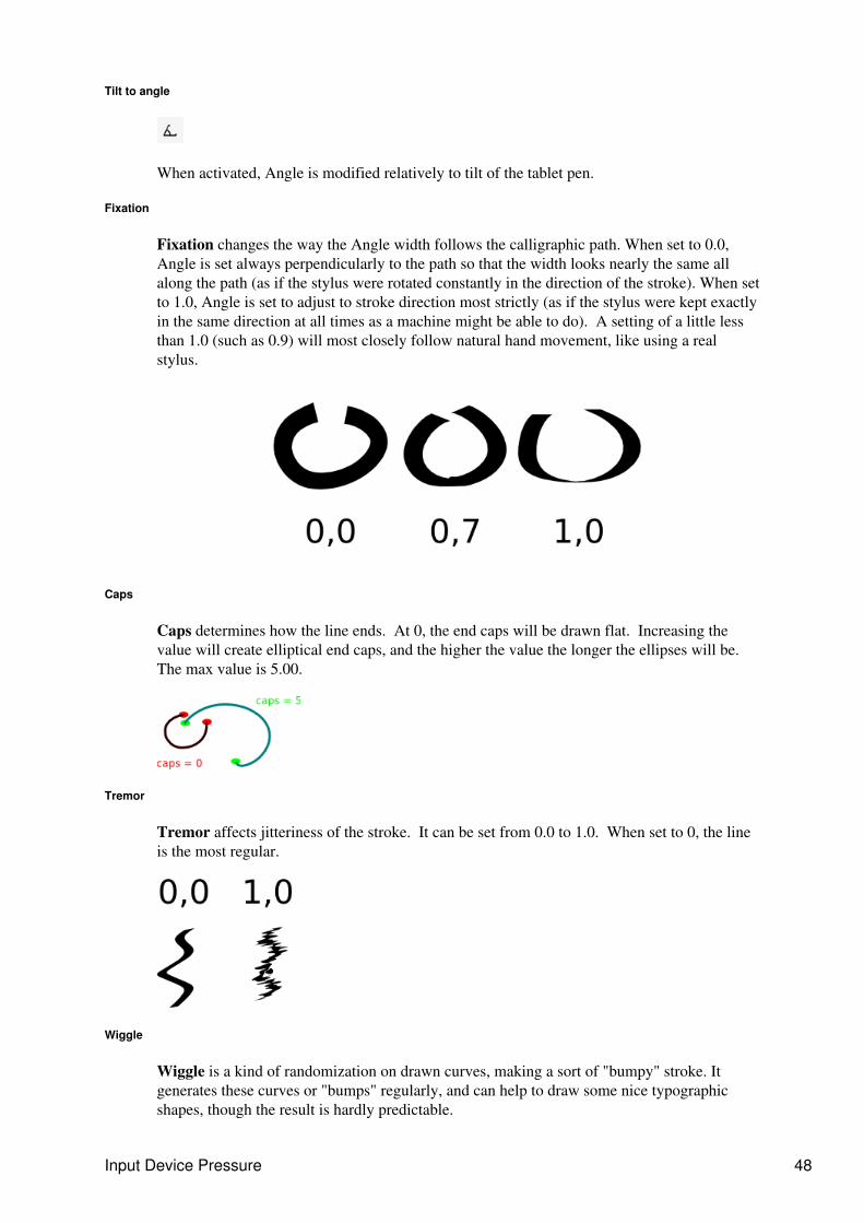
Tilt to angle
When activated, Angle is modified relatively to tilt of the tablet pen.
Fixation
Fixation changes the way the Angle width follows the calligraphic path. When set to 0.0,Angle is set always perpendicularly to the path so that the width looks nearly the same allalong the path (as if the stylus were rotated constantly in the direction of the stroke). When setto 1.0, Angle is set to adjust to stroke direction most strictly (as if the stylus were kept exactlyin the same direction at all times as a machine might be able to do). A setting of a little lessthan 1.0 (such as 0.9) will most closely follow natural hand movement, like using a realstylus.
Caps
Caps determines how the line ends. At 0, the end caps will be drawn flat. Increasing thevalue will create elliptical end caps, and the higher the value the longer the ellipses will be.The max value is 5.00.
Tremor
Tremor affects jitteriness of the stroke. It can be set from 0.0 to 1.0. When set to 0, the lineis the most regular.
Wiggle
Wiggle is a kind of randomization on drawn curves, making a sort of "bumpy" stroke. Itgenerates these curves or "bumps" regularly, and can help to draw some nice typographicshapes, though the result is hardly predictable.
Input Device Pressure 48
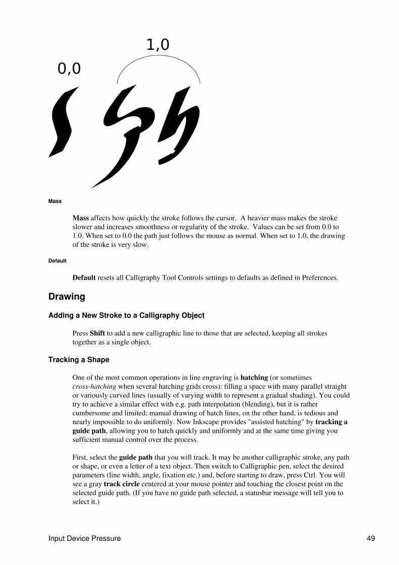
Mass
Mass affects how quickly the stroke follows the cursor. A heavier mass makes the strokeslower and increases smoothness or regularity of the stroke. Values can be set from 0.0 to1.0. When set to 0.0 the path just follows the mouse as normal. When set to 1.0, the drawingof the stroke is very slow.
Default
Default resets all Calligraphy Tool Controls settings to defaults as defined in Preferences.
Drawing
Adding a New Stroke to a Calligraphy Object
Press Shift to add a new calligraphic line to those that are selected, keeping all strokestogether as a single object.
Tracking a Shape
One of the most common operations in line engraving is hatching (or sometimescross-hatching when several hatching grids cross): filling a space with many parallel straightor variously curved lines (usually of varying width to represent a gradual shading). You couldtry to achieve a similar effect with e.g. path interpolation (blending), but it is rathercumbersome and limited; manual drawing of hatch lines, on the other hand, is tedious andnearly impossible to do uniformly. Now Inkscape provides "assisted hatching" by tracking aguide path, allowing you to hatch quickly and uniformly and at the same time giving yousufficient manual control over the process.
First, select the guide path that you will track. It may be another calligraphic stroke, any pathor shape, or even a letter of a text object. Then switch to Calligraphic pen, select the desiredparameters (line width, angle, fixation etc.) and, before starting to draw, press Ctrl. You willsee a gray track circle centered at your mouse pointer and touching the closest point on theselected guide path. (If you have no guide path selected, a statusbar message will tell you toselect it.)
Input Device Pressure 49
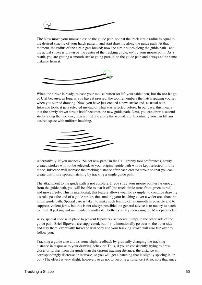
The Now move your mouse close to the guide path, so that the track circle radius is equal tothe desired spacing of your hatch pattern, and start drawing along the guide path. At thatmoment, the radius of the circle gets locked; now the circle slides along the guide path - andthe actual stroke is drawn by the center of the tracking circle, not by your mouse point. As aresult, you are getting a smooth stroke going parallel to the guide path and always at the samedistance from it.
When the stroke is ready, release your mouse button (or lift your tablet pen) but do not let goof Ctrl because, as long as you have it pressed, the tool remembers the hatch spacing you setwhen you started drawing. Now, you have just created a new stroke and, as usual withInkscape tools, it gets selected instead of what was selected before. In our case, this meansthat the newly drawn stroke itself becomes the new guide path. Next, you can draw a secondstroke along the first one, then a third one along the second, etc. Eventually you can fill anydesired space with uniform hatching.
Alternatively, if you uncheck "Select new path" in the Calligraphy tool preferences, newlycreated strokes will not be selected, so your original guide path will be kept selected. In thismode, Inkscape will increase the tracking distance after each created stroke so that you cancreate uniformly spaced hatching by tracking a single guide path.
The attachment to the guide path is not absolute. If you stray your mouse pointer far enoughfrom the guide path, you will be able to tear it off (the track circle turns from green to red)and move freely. This is intentional; this feature allows you, for example, to continue drawinga stroke past the end of a guide stroke, thus making your hatching cover a wider area than theinitial guide path. Special care is taken to make such tearing off as smooth as possible and tosuppress violent jerks, but this is not always possible; the general advice is to not try to hatchtoo fast. If jerking and unintended tearoffs still bother you, try increasing the Mass parameter.
Also, special code is in place to prevent flipovers - accidental jumps to the other side of theguide path. Brief flipovers are suppressed, but if you intentionally go over to the other sideand stay there, eventually Inkscape will obey and your tracking stroke will also flip over tofollow you.
Tracking a guide also allows some slight feedback by gradually changing the trackingdistance in response to your drawing behavior. Thus, if you're consistently trying to drawcloser or farther from the guide than the current tracking distance, the distance willcorrespondingly decrease or increase, so you will get a hatching that is slightly spacing in orout. (The effect is very slight, however, so as not to become a nuisance.) Also, note that since
Tracking a Shape 50

tracking follows the edge of the stroke, strokes of varying width (such as those tracingbackground, see below) will result in gradual bending of the hatching pattern as you proceed
Engraving
Combined with the Ctrl key, the Calligraphy Tool is able to simulate the ancient art of lineengraving. Traditional engraving is a very labour-intensive process, and while for a long timeit was the only practical way of reproducing lifelike images in black-and-white print, about acentury ago it was almost completely displaced by automatic halftone screens in industrialprocess. However, line engravings have their characteristic charm, and are often still used forcertain art applications.
Engraving 51
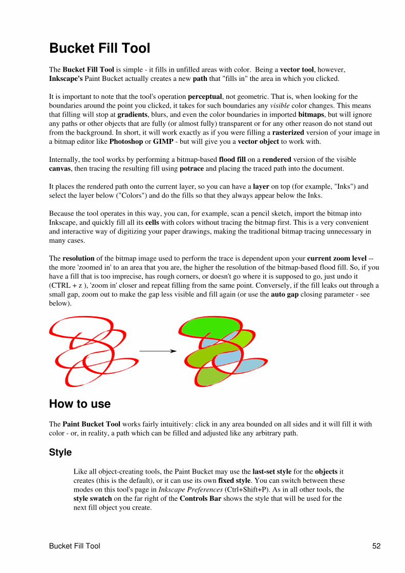
Bucket Fill ToolThe Bucket Fill Tool is simple - it fills in unfilled areas with color. Being a vector tool, however,Inkscape's Paint Bucket actually creates a new path that "fills in" the area in which you clicked.
It is important to note that the tool's operation perceptual, not geometric. That is, when looking for theboundaries around the point you clicked, it takes for such boundaries any visible color changes. This meansthat filling will stop at gradients, blurs, and even the color boundaries in imported bitmaps, but will ignoreany paths or other objects that are fully (or almost fully) transparent or for any other reason do not stand outfrom the background. In short, it will work exactly as if you were filling a rasterized version of your image ina bitmap editor like Photoshop or GIMP - but will give you a vector object to work with.
Internally, the tool works by performing a bitmap-based flood fill on a rendered version of the visiblecanvas, then tracing the resulting fill using potrace and placing the traced path into the document.
It places the rendered path onto the current layer, so you can have a layer on top (for example, "Inks") andselect the layer below ("Colors") and do the fills so that they always appear below the Inks.
Because the tool operates in this way, you can, for example, scan a pencil sketch, import the bitmap intoInkscape, and quickly fill all its cells with colors without tracing the bitmap first. This is a very convenientand interactive way of digitizing your paper drawings, making the traditional bitmap tracing unnecessary inmany cases.
The resolution of the bitmap image used to perform the trace is dependent upon your current zoom level --the more 'zoomed in' to an area that you are, the higher the resolution of the bitmap-based flood fill. So, if youhave a fill that is too imprecise, has rough corners, or doesn't go where it is supposed to go, just undo it(CTRL + z ), 'zoom in' closer and repeat filling from the same point. Conversely, if the fill leaks out through asmall gap, zoom out to make the gap less visible and fill again (or use the auto gap closing parameter - seebelow).
How to use
The Paint Bucket Tool works fairly intuitively: click in any area bounded on all sides and it will fill it withcolor - or, in reality, a path which can be filled and adjusted like any arbitrary path.
Style
Like all object-creating tools, the Paint Bucket may use the last-set style for the objects itcreates (this is the default), or it can use its own fixed style. You can switch between thesemodes on this tool's page in Inkscape Preferences (Ctrl+Shift+P). As in all other tools, thestyle swatch on the far right of the Controls Bar shows the style that will be used for thenext fill object you create.
Bucket Fill Tool 52
Controls
In the Tool Controls bar: Paint Bucket's perceptual fill can use either all visible colors orspecific color channels. Using the Fill by drop-down list, you can restrict the fill algorithm toone the following channels:
Red♦ Green♦ Blue♦ Hue♦ Saturation♦ Lightness♦ Alpha♦
The Threshold (in per cent units) controls how large the color difference must be at a point(compared to the initial click point) to stop the fill. 'Zero tolerance' means only an area whichis strictly the same color will be filled; the larger the tolerance, the easier it will be for the fillto leak into adjacent different-color areas. The default value is 10%.
Using the Grow/shrink by parameter, you can control the amount of inset/outset to beapplied to the created fill path. Setting a positive outset causes fill paths to be larger than thefilled bitmap area (good for eliminating anti-aliasing errors), while setting a negative outsetcauses the path to be smaller. This works much the same as the Outset and Inset pathcommands, except it's done automatically after every fill.
With the Close gaps parameter, you can make the Paint Bucket tool ignore any gaps in thearea boundaries that would normally cause the fill to spill out of the desired area. There arefour settings to auto gap:
None♦ Small (close gaps up to 2 pixels in size)♦ Medium (4 pixels)♦ Large (6 pixels)♦
Note : setting this parameter to anything other than None may slow down Inkscape noticeablywhile filling large areas.
Hotkeys
The tool's shortcuts are:
Single click performs filling from the click point.•
Shift+click performs filling from the click point and then unions the resulting path with the selectedpath. This way, if your first attempt did not fill in all of the desired area, you can Shift+click theremaining corner to fill it in separately and combine the result with the result of the previous fill.
•
Ctrl+click on an object simply changes that object's fill to the current fill color of the tool, andShift+Ctrl+click changes the stroke to the current stroke color.
•
Click+drag performs filling from all of the points that you pass while dragging (you will see yourpath visualized by a red line). From each point, the fill spreads to its neighbours with the colorssimilar to that point - in other words, it's like clicking with this tool at each point of the drag path andjoining the results. This lets you easily fill an area occupied by a gradient or blur - just drag from thedarkest to the lightest points in the area you want to fill.
•
Controls 53

Alt+click and drag works similarly to simple drag, except from each point of the drag path, the fillspreads to the neighbours (if any) with the colors similar to the initial point (the point where youstarted the drag). This lets you fill a series of similarly-colored yet separated areas (for example,multiple cells in a cartoon) by starting the drag in one of those areas, and Alt+dragging the toolthrough all the other areas.
•
Hotkeys 54
Text toolThe Text Tool makes it possible to write text in an SVG drawing.
How to Us
To invoke the tool, press Shift + Ctrl + T. Alternatively there is a Text menu which allows you to change theaspect of the characters or their behavior with respect to other elements of the drawing. Text Tool uses severalshort cut keys to modify typographic elements.
There are two ways to use the Text Tool :
Select the Text Tool and click on the canvas to create a simple line field. It will grow with the writtentext.
1.
Click and drag to draw a rectangle this becomes a text box : this frame will contain the text and willbe the limit for the word wrapping. The text box will not grow with the text, so if there is too muchtext for the frame, some letters will simply not be displayed. This frame can be manually resized bydragging the handle at the bottom right corner. The Flow into Frame command of the Text menumakes it easy to use any shape as a text container.
2.
Special Characters
Ctrl +Space inserts on non-breaking space•
Ctrl U allows to use Unicode encodings within the document. To find a Unicode value refer to aUnicode character map program or reference.
•
To insert an arbitrary Unicode character, type Ctrl + U, then the hexadecimal code, thenEnter. For example, type Ctrl U 2 0 1 4 Enter for an em-dash; Ctrl + U a 9 + Enter for acopyright sign.
♦
To stay in Unicode mode after inserting the character, press Space instead of Enter♦ Press Esc or another Ctrl U to cancel Unicode mode without inserting the character. ♦
Tips
If you're not sure all your text is not visible in the frame, use the Text and Font window to read it all.•
Text tool 55
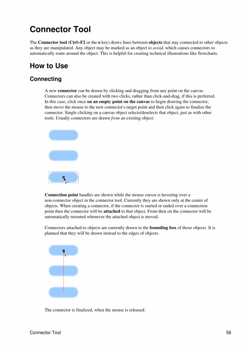
Connector ToolThe Connector tool (Ctrl+F2 or the o key) draws lines between objects that stay connected to other objectsas they are manipulated. Any object may be marked as an object to avoid, which causes connectors toautomatically route around the object. This is helpful for creating technical illustrations like flowcharts.
How to Use
Connecting
A new connector can be drawn by clicking and dragging from any point on the canvas.Connectors can also be created with two clicks, rather than click-and-drag, if this is preferred.In this case, click once on an empty point on the canvas to begin drawing the connector,then move the mouse to the new connector's target point and then click again to finalize theconnector. Single clicking on a canvas object selects/deselects that object, just as with othertools. Usually connectors are drawn from an existing object:
Connection point handles are shown while the mouse cursor is hovering over anon-connector object in the connector tool. Currently they are shown only at the center ofobjects. When creating a connector, if the connector is started or ended over a connectionpoint then the connector will be attached to that object. From then on the connector will beautomatically rerouted whenever the attached object is moved.
Connectors attached to objects are currently drawn to the bounding box of those objects. It isplanned that they will be drawn instead to the edges of objects.
The connector is finalized, when the mouse is released:
Connector Tool 56
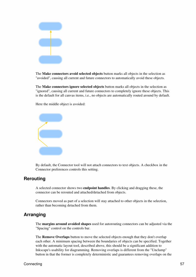
The Make connectors avoid selected objects button marks all objects in the selection as"avoided", causing all current and future connectors to automatically avoid these objects.
The Make connectors ignore selected objects button marks all objects in the selection as"ignored", causing all current and future connectors to completely ignore these objects. Thisis the default for all canvas items, i.e., no objects are automatically routed around by default.
Here the middle object is avoided:
By default, the Connector tool will not attach connectors to text objects. A checkbox in theConnector preferences controls this setting.
Rerouting
A selected connector shows two endpoint handles. By clicking and dragging these, theconnector can be rerouted and attached/detached from objects.
Connectors moved as part of a selection will stay attached to other objects in the selection,rather than becoming detached from them.
Arranging
The margins around avoided shapes used for autorouting connectors can be adjusted via the"Spacing" control on the controls bar.
The Remove Overlaps button to move the selected objects enough that they don't overlapeach other. A minimum spacing between the boundaries of objects can be specified. Togetherwith the automatic layout tool, described above, this should be a significant addition toInkscape's usability for diagramming. Removing overlaps is different from the "Unclump"button in that the former is completely deterministic and guarantees removing overlaps on the
Connecting 57

first application, but is not concerned with visual perceptive distances between objects.Unclumping, on the other hand, attempts to equalize perceptive distances between objects andcan be applied repeatedly for gradual effect.
Automatic Diagram Layout: this function is available in the Align and Distribute dialogand performs automatic layout of diagrams involving a network of shapes and connectors.Edges are treated as if they are springs such that the distance between nodes will beproportional to the path length � number of connectors � between them. Disconnectedcomponents (where not every shape is connected) will be arranged around the circumferenceof a circle.
Arranging 58
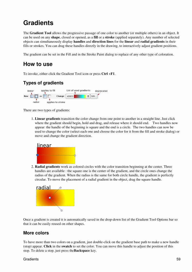
GradientsThe Gradient Tool allows the progressive passage of one color to another (or multiple others) in an object. Itcan be used on any shape, closed or opened, as a fill or a stroke (applied separately). Any number of selectedobjects can simultaneously display handles and direction lines for the linear and radial gradients in theirfills or strokes. You can drag these handles directly in the drawing, to interactively adjust gradient positions.
The gradient can be set in the Fill and in the Stroke Paint dialog to replace of any other type of coloration.
How to use
To invoke, either click the Gradient Tool icon or press Ctrl +F1.
Types of gradients
There are two types of gradients:
Linear gradients transition the color change from one point to another in a straight line. Just clickwhere the gradient should begin, hold and drag, and release where it should end. Two handles nowappear: the handle of the beginning is square and the end is a circle. The two handles can now beused to change the color (select each one and choose the color for it from the fill and stroke dialog) ormove and change the gradient direction.
1.
Radial gradients work as colored circles with the color transition beginning at the center. Threehandles are available : the square one is the center of the gradient, and the circle ones change theradius of the gradient. When the radius is the same for both circle handle, the gradient is perfectlycircular. To move the placement of a radial gradient in the object, drag the square handle.
2.
Once a gradient is created it is automatically saved in the drop-down list of the Gradient Tool Options bar sothat it can be easily reused on other shapes.
More colors
To have more than two colors on a gradient, just double-click on the gradient base path to make a new handle(stop) appear. Click in the swatch to set the color. You can move this handle to adjust the position of thisstop. To delete a stop, just press theBackspace key.
Gradients 59
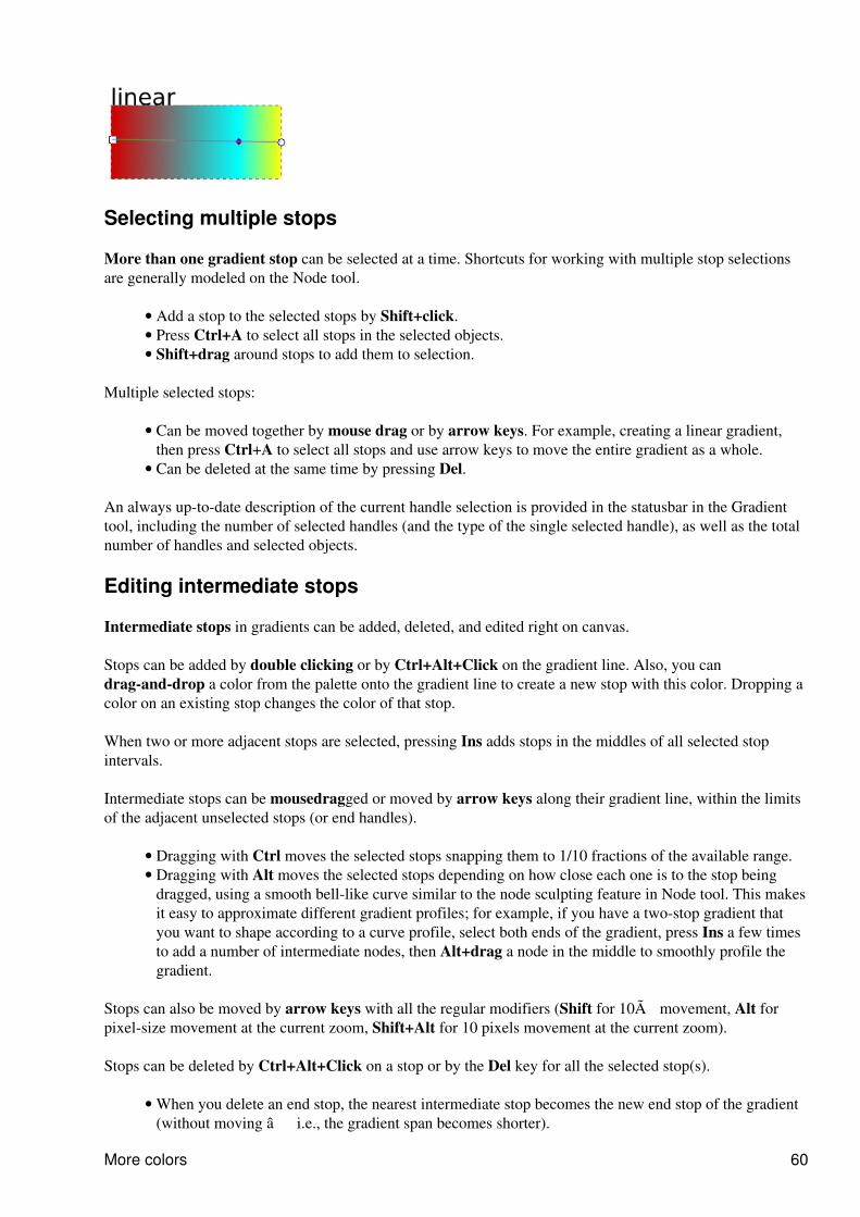
Selecting multiple stops
More than one gradient stop can be selected at a time. Shortcuts for working with multiple stop selectionsare generally modeled on the Node tool.
Add a stop to the selected stops by Shift+click.• Press Ctrl+A to select all stops in the selected objects.• Shift+drag around stops to add them to selection.•
Multiple selected stops:
Can be moved together by mouse drag or by arrow keys. For example, creating a linear gradient,then press Ctrl+A to select all stops and use arrow keys to move the entire gradient as a whole.
•
Can be deleted at the same time by pressing Del.•
An always up-to-date description of the current handle selection is provided in the statusbar in the Gradienttool, including the number of selected handles (and the type of the single selected handle), as well as the totalnumber of handles and selected objects.
Editing intermediate stops
Intermediate stops in gradients can be added, deleted, and edited right on canvas.
Stops can be added by double clicking or by Ctrl+Alt+Click on the gradient line. Also, you candrag-and-drop a color from the palette onto the gradient line to create a new stop with this color. Dropping acolor on an existing stop changes the color of that stop.
When two or more adjacent stops are selected, pressing Ins adds stops in the middles of all selected stopintervals.
Intermediate stops can be mousedragged or moved by arrow keys along their gradient line, within the limitsof the adjacent unselected stops (or end handles).
Dragging with Ctrl moves the selected stops snapping them to 1/10 fractions of the available range.• Dragging with Alt moves the selected stops depending on how close each one is to the stop beingdragged, using a smooth bell-like curve similar to the node sculpting feature in Node tool. This makesit easy to approximate different gradient profiles; for example, if you have a two-stop gradient thatyou want to shape according to a curve profile, select both ends of the gradient, press Ins a few timesto add a number of intermediate nodes, then Alt+drag a node in the middle to smoothly profile thegradient.
•
Stops can also be moved by arrow keys with all the regular modifiers (Shift for 10� movement, Alt forpixel-size movement at the current zoom, Shift+Alt for 10 pixels movement at the current zoom).
Stops can be deleted by Ctrl+Alt+Click on a stop or by the Del key for all the selected stop(s).
When you delete an end stop, the nearest intermediate stop becomes the new end stop of the gradient(without moving � i.e., the gradient span becomes shorter).
•
More colors 60
When you delete an end stop and there are no intermediate stops, the object will be painted with asolid fill taken from the color & opacity of the remaining stop.
•
Pressing Ctrl+L with some intermediate stops selected attempts to simplify the selected portion of thegradient, removing those stops that can be removed without too much change in the way the gradient looks. Inparticular, new stops created by double-clicking or pressing Ins initially do not change the appearance of thegradient, so if you press Ctrl+L, all redundant stops that weren't moved or repainted since creation will bedeleted.
Automatic duplication of gradients
When copy/pasting or duplicating an object with gradient, it automatically gets a copy of the originalgradient, so modifying it does not affect the source object's gradient anymore .
However, to accommodate the needs of users who rely on sharing the same gradient definition across objects,this behavior can be optionally suppressed. The Prevent sharing of gradient definitions checkbox on theMisc tab of Inkscape Preferences is by default checked; if you uncheck it, Inkscape does not automaticallycopy gradient definitions for new objects, which means that copy/pasting, duplicating, pasting style, andexplicit assignment of a gradient to an object via the Gradient tool controls results in a shared gradientdefinition, so that changing the colors or mid-stop positions of the gradient on one object (but not changingthe coordinates of the end handles) affects all other objects that share the same definition.
Editing intermediate stops 61
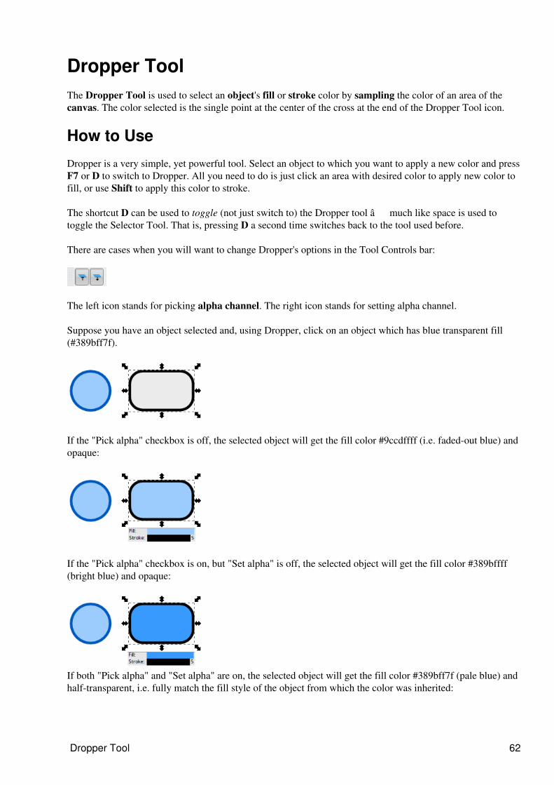
Dropper ToolThe Dropper Tool is used to select an object's fill or stroke color by sampling the color of an area of thecanvas. The color selected is the single point at the center of the cross at the end of the Dropper Tool icon.
How to Use
Dropper is a very simple, yet powerful tool. Select an object to which you want to apply a new color and pressF7 or D to switch to Dropper. All you need to do is just click an area with desired color to apply new color tofill, or use Shift to apply this color to stroke.
The shortcut D can be used to toggle (not just switch to) the Dropper tool � much like space is used totoggle the Selector Tool. That is, pressing D a second time switches back to the tool used before.
There are cases when you will want to change Dropper's options in the Tool Controls bar:
The left icon stands for picking alpha channel. The right icon stands for setting alpha channel.
Suppose you have an object selected and, using Dropper, click on an object which has blue transparent fill(#389bff7f).
If the "Pick alpha" checkbox is off, the selected object will get the fill color #9ccdffff (i.e. faded-out blue) andopaque:
If the "Pick alpha" checkbox is on, but "Set alpha" is off, the selected object will get the fill color #389bffff(bright blue) and opaque:
If both "Pick alpha" and "Set alpha" are on, the selected object will get the fill color #389bff7f (pale blue) andhalf-transparent, i.e. fully match the fill style of the object from which the color was inherited:
Dropper Tool 62
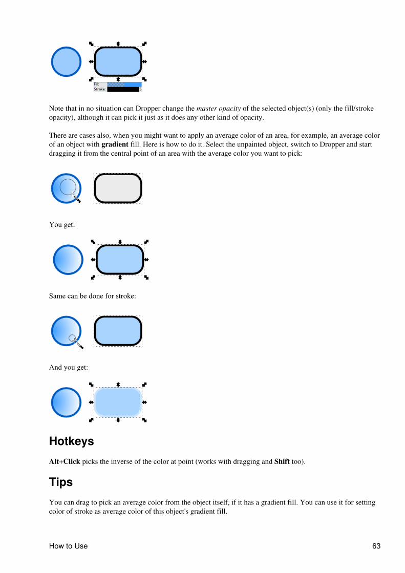
Note that in no situation can Dropper change the master opacity of the selected object(s) (only the fill/strokeopacity), although it can pick it just as it does any other kind of opacity.
There are cases also, when you might want to apply an average color of an area, for example, an average colorof an object with gradient fill. Here is how to do it. Select the unpainted object, switch to Dropper and startdragging it from the central point of an area with the average color you want to pick:
You get:
Same can be done for stroke:
And you get:
Hotkeys
Alt+Click picks the inverse of the color at point (works with dragging and Shift too).
Tips
You can drag to pick an average color from the object itself, if it has a gradient fill. You can use it for settingcolor of stroke as average color of this object's gradient fill.
How to Use 63
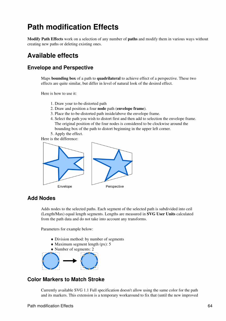
Path modification EffectsModify Path Effects work on a selection of any number of paths and modify them in various ways withoutcreating new paths or deleting existing ones.
Available effects
Envelope and Perspective
Maps bounding box of a path to quadrilateral to achieve effect of a perspective. These twoeffects are quite similar, but differ in level of natural look of the desired effect.
Here is how to use it:
Draw your to-be-distorted path1. Draw and position a four node path (envelope frame).2. Place the to-be-distorted path inside/above the envelope frame.3. Select the path you wish to distort first and then add to selection the envelope frame.The original position of the four nodes is considered to be clockwise around thebounding box of the path to distort beginning in the upper left corner.
4.
Apply the effect.5. Here is the difference:
Add Nodes
Adds nodes to the selected paths. Each segment of the selected path is subdivided into ceil(Length/Max) equal length segments. Lengths are measured in SVG User Units calculatedfrom the path data and do not take into account any transforms.
Parameters for example below:
Division method: by number of segments♦ Maximum segment length (px): 5♦ Number of segments: 2♦
Color Markers to Match Stroke
Currently available SVG 1.1 Full specification doesn't allow using the same color for the pathand its markers. This extension is a temporary workaround to fix that (until the new improved
Path modification Effects 64
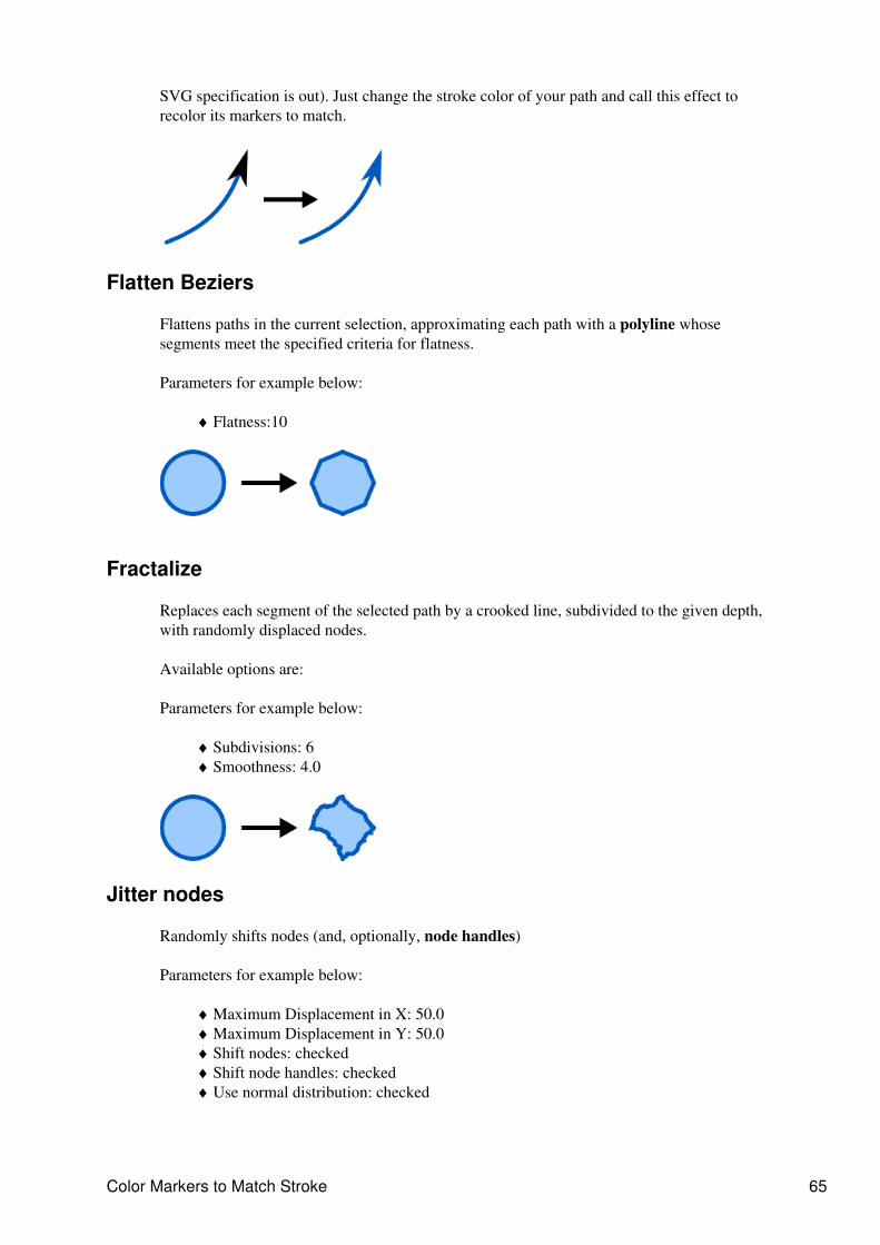
SVG specification is out). Just change the stroke color of your path and call this effect torecolor its markers to match.
Flatten Beziers
Flattens paths in the current selection, approximating each path with a polyline whosesegments meet the specified criteria for flatness.
Parameters for example below:
Flatness:10♦
Fractalize
Replaces each segment of the selected path by a crooked line, subdivided to the given depth,with randomly displaced nodes.
Available options are:
Parameters for example below:
Subdivisions: 6♦ Smoothness: 4.0♦
Jitter nodes
Randomly shifts nodes (and, optionally, node handles)
Parameters for example below:
Maximum Displacement in X: 50.0♦ Maximum Displacement in Y: 50.0♦ Shift nodes: checked♦ Shift node handles: checked♦ Use normal distribution: checked♦
Color Markers to Match Stroke 65
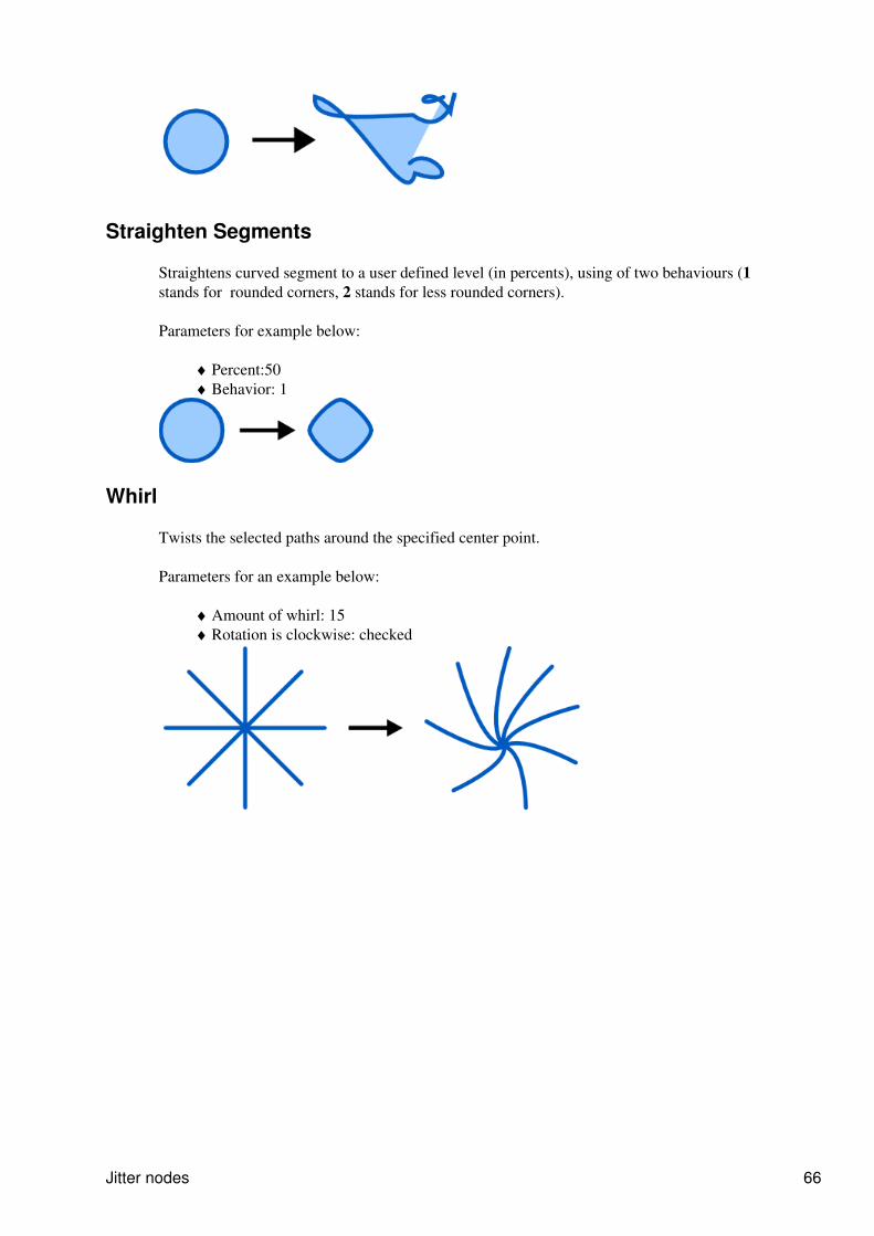
Straighten Segments
Straightens curved segment to a user defined level (in percents), using of two behaviours (1stands for rounded corners, 2 stands for less rounded corners).
Parameters for example below:
Percent:50♦ Behavior: 1♦
Whirl
Twists the selected paths around the specified center point.
Parameters for an example below:
Amount of whirl: 15♦ Rotation is clockwise: checked♦
Jitter nodes 66
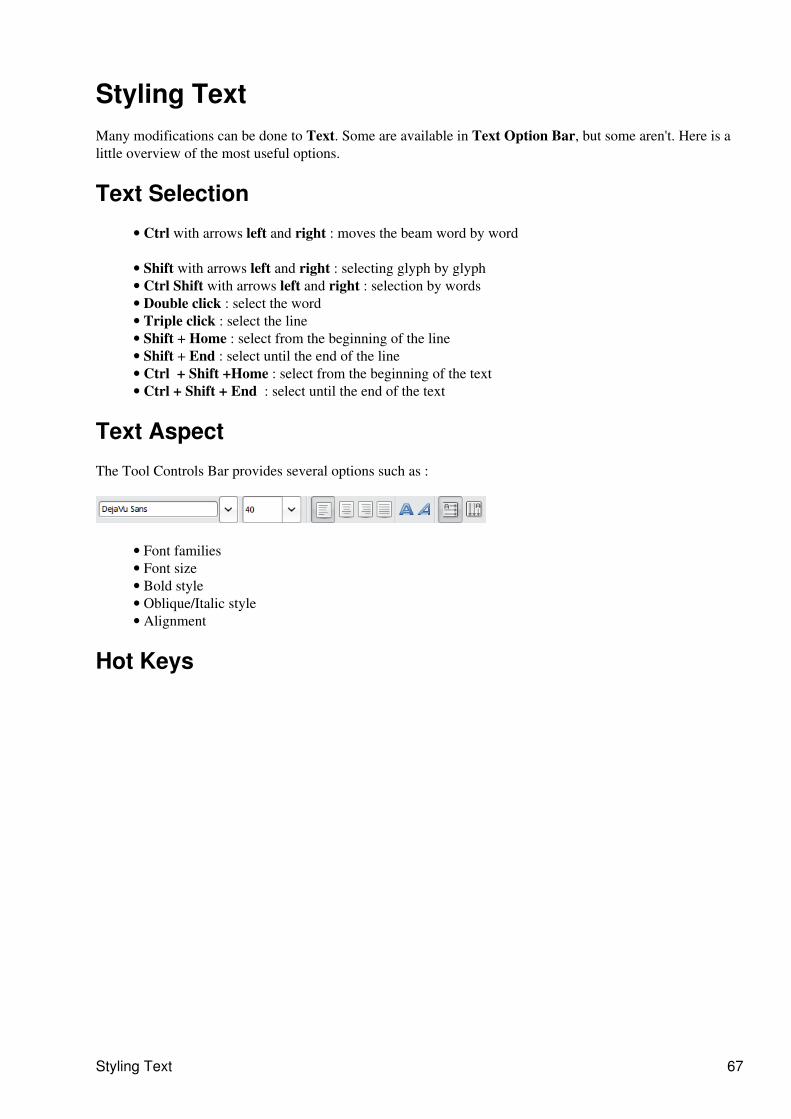
Styling Text Many modifications can be done to Text. Some are available in Text Option Bar, but some aren't. Here is alittle overview of the most useful options.
Text Selection
Ctrl with arrows left and right : moves the beam word by word•
Shift with arrows left and right : selecting glyph by glyph• Ctrl Shift with arrows left and right : selection by words• Double click : select the word• Triple click : select the line• Shift + Home : select from the beginning of the line • Shift + End : select until the end of the line• Ctrl + Shift +Home : select from the beginning of the text• Ctrl + Shift + End : select until the end of the text•
Text Aspect
The Tool Controls Bar provides several options such as :
Font families• Font size• Bold style• Oblique/Italic style• Alignment•
Hot Keys
Styling Text 67

Ctrl +B and Ctrl + I applies bold and italic to the selected text. • Kerning : Alt with arrows left and right increase or decrease the space between caracters at the endor beginning ofthe selection. You can also use Alt + >, Alt <, Shift +Alt + >, or Shift + Alt + < tochange the letter spacing more significantly. Use the Remove manual kerns menu of the Text menu ifyour are not satisfied with it.
•
Pressing Alt + [, Alt +] rotates precisely the letters; Ctrl + [, Ctrl + ] do 90° rotation at once. •
Alt arrows up and down change the vertical position of the selected text relatively to the baseline.•
68
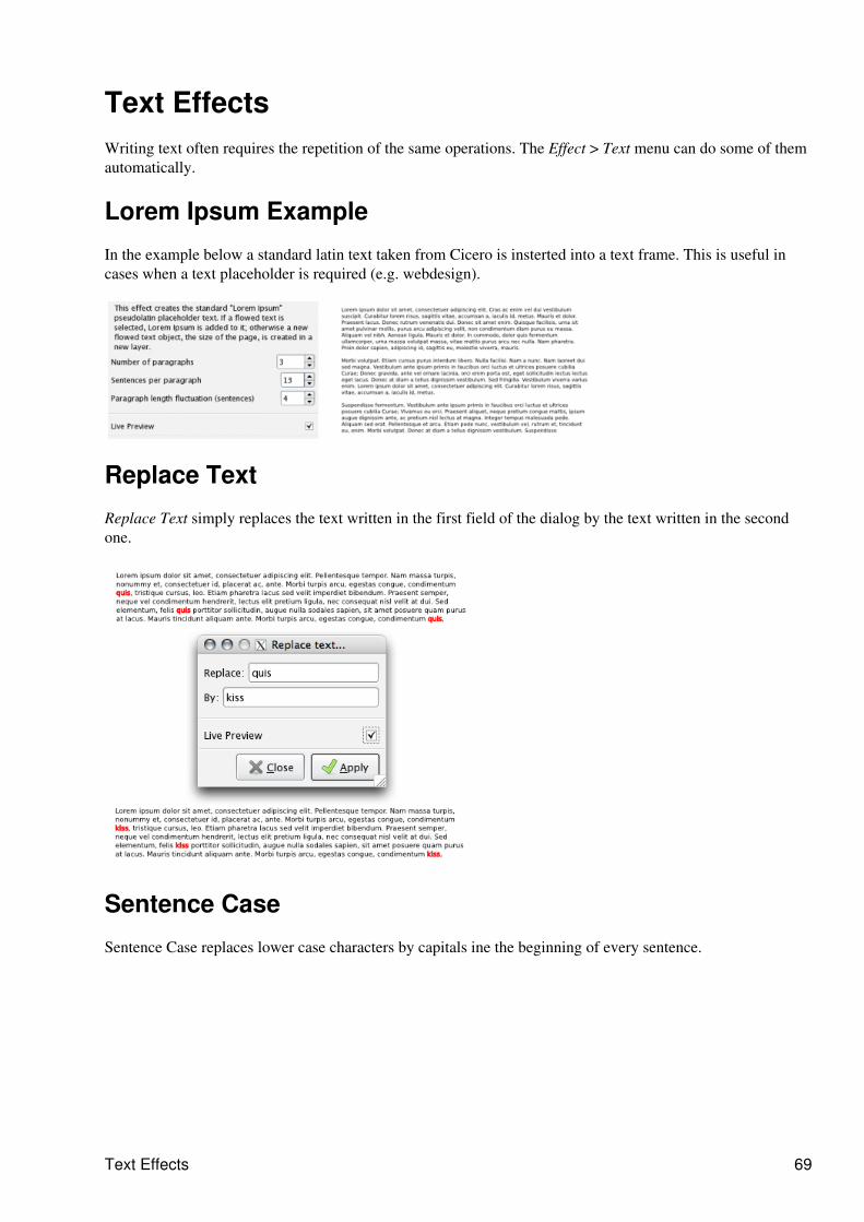
Text EffectsWriting text often requires the repetition of the same operations. The Effect > Text menu can do some of themautomatically.
Lorem Ipsum Example
In the example below a standard latin text taken from Cicero is insterted into a text frame. This is useful incases when a text placeholder is required (e.g. webdesign).
Replace Text
Replace Text simply replaces the text written in the first field of the dialog by the text written in the secondone.
Sentence Case
Sentence Case replaces lower case characters by capitals ine the beginning of every sentence.
Text Effects 69
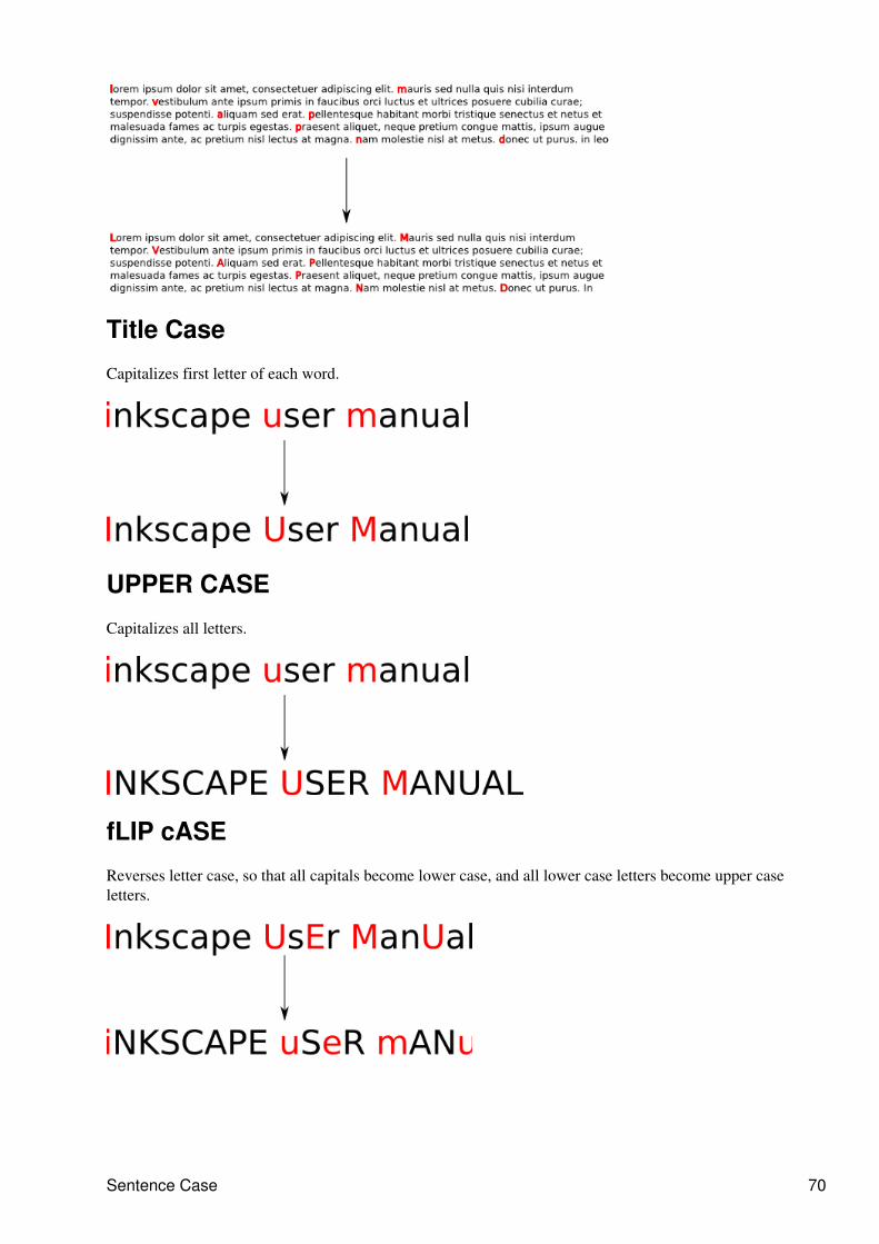
Title Case
Capitalizes first letter of each word.
UPPER CASE
Capitalizes all letters.
fLIP cASE
Reverses letter case, so that all capitals become lower case, and all lower case letters become upper caseletters.
Sentence Case 70
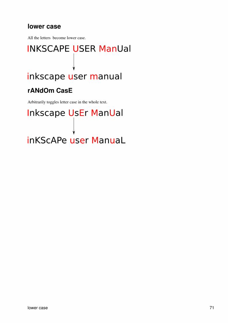
lower case
All the letters become lower case.
rANdOm CasE
Arbitrarily toggles letter case in the whole text.
lower case 71
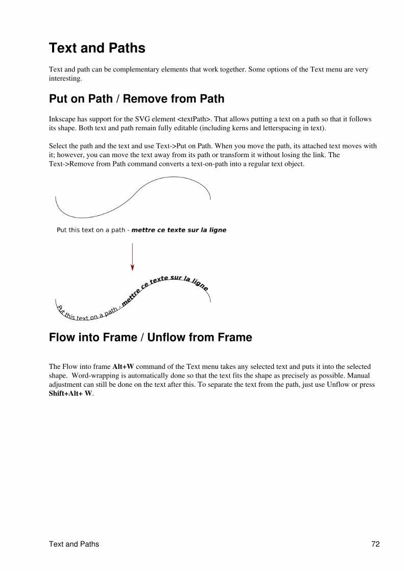
Text and PathsText and path can be complementary elements that work together. Some options of the Text menu are veryinteresting.
Put on Path / Remove from Path
Inkscape has support for the SVG element <textPath>. That allows putting a text on a path so that it followsits shape. Both text and path remain fully editable (including kerns and letterspacing in text).
Select the path and the text and use Text->Put on Path. When you move the path, its attached text moves withit; however, you can move the text away from its path or transform it without losing the link. TheText->Remove from Path command converts a text-on-path into a regular text object.
Flow into Frame / Unflow from Frame
The Flow into frame Alt+W command of the Text menu takes any selected text and puts it into the selectedshape. Word-wrapping is automatically done so that the text fits the shape as precisely as possible. Manualadjustment can still be done on the text after this. To separate the text from the path, just use Unflow or pressShift+Alt+ W.
Text and Paths 72
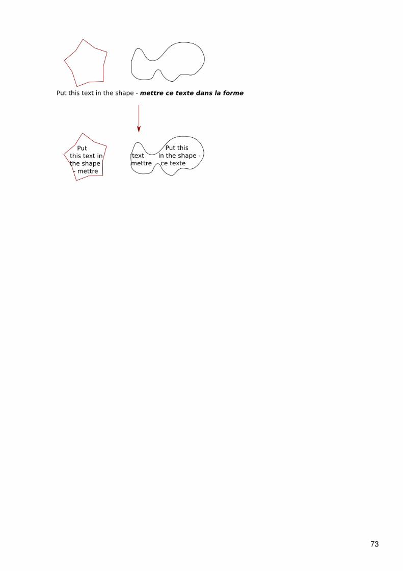
73
Copy, Clone and Duplicate
Introduction
The artist may have need, at some point in his work, to replicate an object he has created for any number ofpurposes. Possibly he is populating a scene with bubbles or blades of grass which will all look exactly alike,or else he may want to create a very similar object which has some minor modifications.
Fortunately, Inkscape offers several tools to replicate objects. Each one has advantages in disadvantages, ofcourse, which will be defined also by the purpose of the replicant object.
A strict copy of an object repeats the object on screen and within the xml code, and the new object is entirelyseparate from the original. This means that changes can be made to the replicant indifferently to the original,and changes made to the original do not affect the replicant either. This is done with either the Copy orDuplicate commands.
A clone is merely a repetition of the original on screen and in the code. Most modifications made to theoriginal, like fill and transparency, are transferred to the replicant as well, and only a few modifications, suchas transform and position, may be made to the replicant directly (some of these only under certaincircumstances). Clones are created with the Clone command.
How to Use
Copy
The Copy command ( Ctrl + C or Edit > Copy or the command bar button) makes an exact copy of theselection in Inkscape's memory; the Paste command ( Ctrl + V or Edit > Paste or the command bar button)puts an exact copy under the cursor. The last selection to be copied can be pasted an indefinite number oftimes. It is also possible to paste the object wherever it is needed, for instance on an other layer, without thetrouble of having to reposition the copy after its creation.
Duplicate
The Duplicate command ( Ctrl + D or Edit > Duplicate ) allows you to copy and paste a selectionautomatically with one command. The new object or selection is in exactly the same position as the originaland is selected (instead of the original), ready for further manipulation.
Clone
The Clone command ( Alt + D or Edit > Clone ) allows you to create a copy of the selection that is linked tothe original, also known as its parent. The clone's shape, style (fill and stroke, transparency) and dimensionsare linked to its parent. Thus, editing the parent's transparency (etc.) will also affect the clone's transparency.
You can clone multiple object by grouping them first.
A clone can be a parent to another clone. Any modifications to the original will affect all clones down thehierarchy of clones.
The fill and stroke paint of a clone is the same as its parent's unless the parent has "Unset paint" activated foreither in the Fill and Stroke dialog. Unsetting fill will make the parent's fill black as well as the clone's, but theclone's fill can then be reset while the parent's cannot; unsetting stroke paint will make the stroke disappear sothat the clone's stroke and stroke paint can be adjusted while the parent's cannot (it will remain invisible
Copy, Clone and Duplicate 74

unless paint is reset for the parent).
Unlink clone
Unlink clone ( Alt + Shift + D or Edit > Clone > Unlink clone ) separates a clone definitively from its parent,effectively making it only a copy. After that you can apply changes to the parent without changing the copy.Select original
Use Select original ( Shift + D or Edit > Clone > Select original ) to find the parent of a selected clone. Thisis very useful when you have lost your parent.
Clone 75
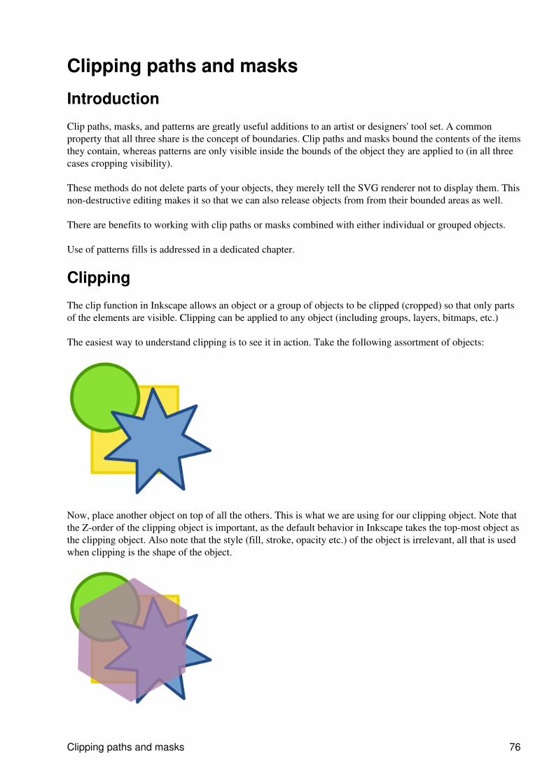
Clipping paths and masks
Introduction
Clip paths, masks, and patterns are greatly useful additions to an artist or designers' tool set. A commonproperty that all three share is the concept of boundaries. Clip paths and masks bound the contents of the itemsthey contain, whereas patterns are only visible inside the bounds of the object they are applied to (in all threecases cropping visibility).
These methods do not delete parts of your objects, they merely tell the SVG renderer not to display them. Thisnon-destructive editing makes it so that we can also release objects from from their bounded areas as well.
There are benefits to working with clip paths or masks combined with either individual or grouped objects.
Use of patterns fills is addressed in a dedicated chapter.
Clipping
The clip function in Inkscape allows an object or a group of objects to be clipped (cropped) so that only partsof the elements are visible. Clipping can be applied to any object (including groups, layers, bitmaps, etc.)
The easiest way to understand clipping is to see it in action. Take the following assortment of objects:
Now, place another object on top of all the others. This is what we are using for our clipping object. Note thatthe Z-order of the clipping object is important, as the default behavior in Inkscape takes the top-most object asthe clipping object. Also note that the style (fill, stroke, opacity etc.) of the object is irrelevant, all that is usedwhen clipping is the shape of the object.
Clipping paths and masks 76
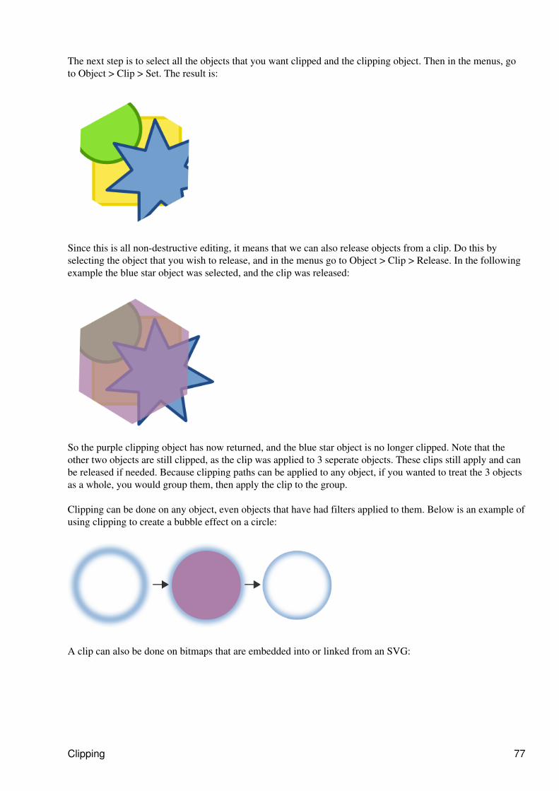
The next step is to select all the objects that you want clipped and the clipping object. Then in the menus, goto Object > Clip > Set. The result is:
Since this is all non-destructive editing, it means that we can also release objects from a clip. Do this byselecting the object that you wish to release, and in the menus go to Object > Clip > Release. In the followingexample the blue star object was selected, and the clip was released:
So the purple clipping object has now returned, and the blue star object is no longer clipped. Note that theother two objects are still clipped, as the clip was applied to 3 seperate objects. These clips still apply and canbe released if needed. Because clipping paths can be applied to any object, if you wanted to treat the 3 objectsas a whole, you would group them, then apply the clip to the group.
Clipping can be done on any object, even objects that have had filters applied to them. Below is an example ofusing clipping to create a bubble effect on a circle:
A clip can also be done on bitmaps that are embedded into or linked from an SVG:
Clipping 77
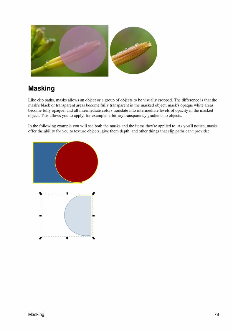
Masking
Like clip paths, masks allows an object or a group of objects to be visually cropped. The difference is that themask's black or transparent areas become fully transparent in the masked object; mask's opaque white areasbecome fully opaque; and all intermediate colors translate into intermediate levels of opacity in the maskedobject. This allows you to apply, for example, arbitrary transparency gradients to objects.
In the following example you will see both the masks and the items they're applied to. As you'll notice, masksoffer the ability for you to texture objects, give them depth, and other things that clip paths can't provide:
Masking 78
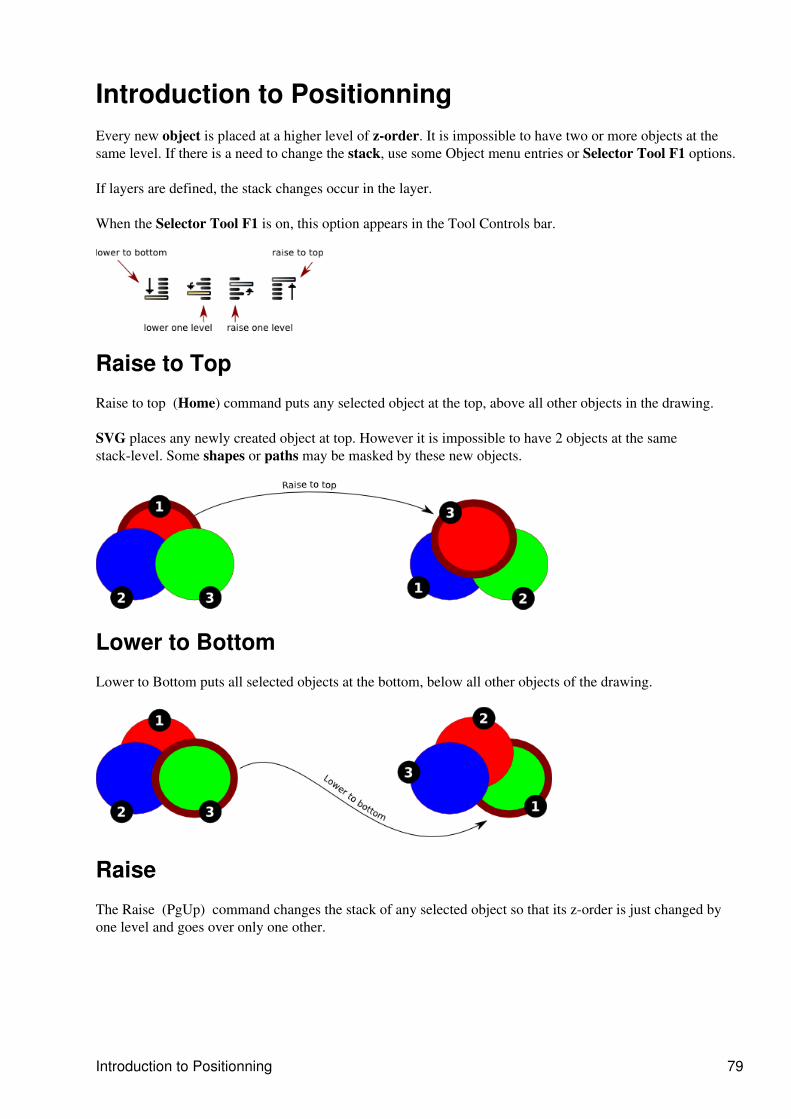
Introduction to Positionning Every new object is placed at a higher level of z-order. It is impossible to have two or more objects at thesame level. If there is a need to change the stack, use some Object menu entries or Selector Tool F1 options.
If layers are defined, the stack changes occur in the layer.
When the Selector Tool F1 is on, this option appears in the Tool Controls bar.
Raise to Top
Raise to top (Home) command puts any selected object at the top, above all other objects in the drawing.
SVG places any newly created object at top. However it is impossible to have 2 objects at the samestack-level. Some shapes or paths may be masked by these new objects.
Lower to Bottom
Lower to Bottom puts all selected objects at the bottom, below all other objects of the drawing.
Raise
The Raise (PgUp) command changes the stack of any selected object so that its z-order is just changed byone level and goes over only one other.
Introduction to Positionning 79
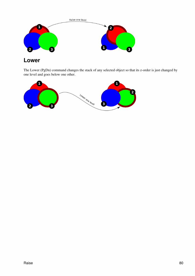
Lower
The Lower (PgDn) command changes the stack of any selected object so that its z-order is just changed byone level and goes below one other.
Raise 80

Align and DistributeAlign and Distribute moves multiple selected objects to the same axis and distributes them equally relativeto a selected anchor object. The Align and Distribute dialog offers many ways of applying these functions toobject selections.
Align and Distribute 81
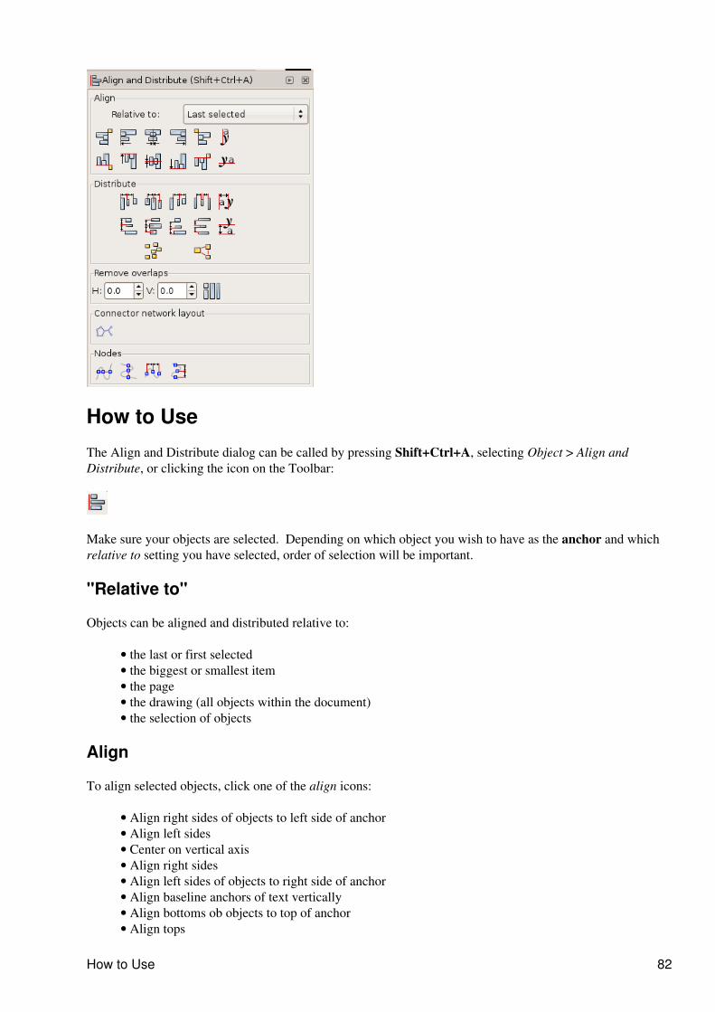
How to Use
The Align and Distribute dialog can be called by pressing Shift+Ctrl+A, selecting Object > Align andDistribute, or clicking the icon on the Toolbar:
Make sure your objects are selected. Depending on which object you wish to have as the anchor and whichrelative to setting you have selected, order of selection will be important.
"Relative to"
Objects can be aligned and distributed relative to:
the last or first selected• the biggest or smallest item• the page• the drawing (all objects within the document)• the selection of objects•
Align
To align selected objects, click one of the align icons:
Align right sides of objects to left side of anchor• Align left sides• Center on vertical axis• Align right sides• Align left sides of objects to right side of anchor• Align baseline anchors of text vertically• Align bottoms ob objects to top of anchor• Align tops•
How to Use 82
Center on horizontal axis• Align bottoms• Align tops of objects to bottom of anchor• Align baseline anchors of texts horizontally•
Distribute
To distribute selected objects, click one of the distribute icons:
Distribute left sides equidistanly• Distribute centers equidistanly horizontally• Distribute right sides equidistanly• Make horizontal gaps between objects equal• Distribute baseline anchors of text horizontally• Distribute tops euidistanly• Distribute centers equidistanly vertically• Distribute bottoms equidistanly• Make vertical gaps between objects equal• Distribute baseline anchors of text vertically• Randomize centers in both dimensions• Unclump objects ; try to equalize edge-to-edge distances•
Remove overlaps
You can also define:
Minimum horizontal gaps between objects,• Mimimum vertical gaps,• Move objects as little as possible so that their bounding boxes do not overlap•
Connector network layout
If you are using the connector tool and need to distribute the connected objects, use this button to rearrangethe selected connectors.
Nodes
There are 4 buttons to organize nodes in path. Select the nodes with Node Tool and click one of the node alignbuttons:
Align selected nodes horizontally• Align selected nodes vertically• Distribute selected nodes horizontally• Distribute selected nodes vertically•
Align 83
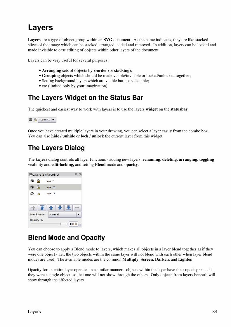
LayersLayers are a type of object group within an SVG document. As the name indicates, they are like stackedslices of the image which can be stacked, arranged, added and removed. In addition, layers can be locked andmade invisible to ease editing of objects within other layers of the document.
Layers can be very useful for several purposes:
Arranging sets of objects by z-order (or stacking);• Grouping objects which should be made visible/invisible or locked/unlocked together;• Setting background layers which are visible but not selectable;• etc (limited only by your imagination)•
The Layers Widget on the Status Bar
The quickest and easiest way to work with layers is to use the layers widget on the statusbar.
Once you have created multiple layers in your drawing, you can select a layer easily from the combo box. You can also hide / unhide or lock / unlock the current layer from this widget.
The Layers Dialog
The Layers dialog controls all layer functions - adding new layers, renaming, deleting, arranging, togglingvisibility and edit-locking, and setting Blend mode and opacity.
Blend Mode and Opacity
You can choose to apply a Blend mode to layers, which makes all objects in a layer blend together as if theywere one object - i.e., the two objects within the same layer will not blend with each other when layer blendmodes are used. The available modes are the common Multiply, Screen, Darken, and Lighten.
Opacity for an entire layer operates in a similar manner - objects within the layer have their opacity set as ifthey were a single object, so that one will not show through the others. Only objects from layers beneath willshow through the affected layers.
Layers 84
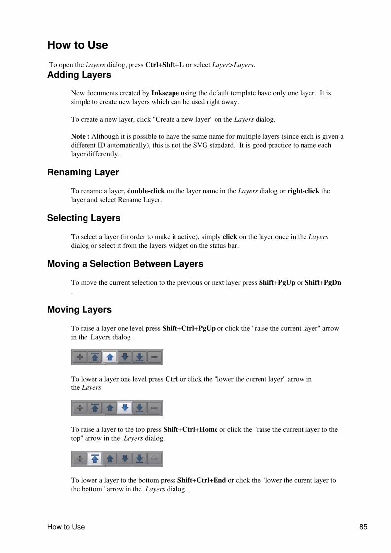
How to Use
To open the Layers dialog, press Ctrl+Shft+L or select Layer>Layers.Adding Layers
New documents created by Inkscape using the default template have only one layer. It issimple to create new layers which can be used right away.
To create a new layer, click "Create a new layer" on the Layers dialog.
Note : Although it is possible to have the same name for multiple layers (since each is given adifferent ID automatically), this is not the SVG standard. It is good practice to name eachlayer differently.
Renaming Layer
To rename a layer, double-click on the layer name in the Layers dialog or right-click thelayer and select Rename Layer.
Selecting Layers
To select a layer (in order to make it active), simply click on the layer once in the Layersdialog or select it from the layers widget on the status bar.
Moving a Selection Between Layers
To move the current selection to the previous or next layer press Shift+PgUp or Shift+PgDn.
Moving Layers
To raise a layer one level press Shift+Ctrl+PgUp or click the "raise the current layer" arrowin the Layers dialog.
To lower a layer one level press Ctrl or click the "lower the current layer" arrow inthe Layers
To raise a layer to the top press Shift+Ctrl+Home or click the "raise the current layer to thetop" arrow in the Layers dialog.
To lower a layer to the bottom press Shift+Ctrl+End or click the "lower the curent layer tothe bottom" arrow in the Layers dialog.
How to Use 85
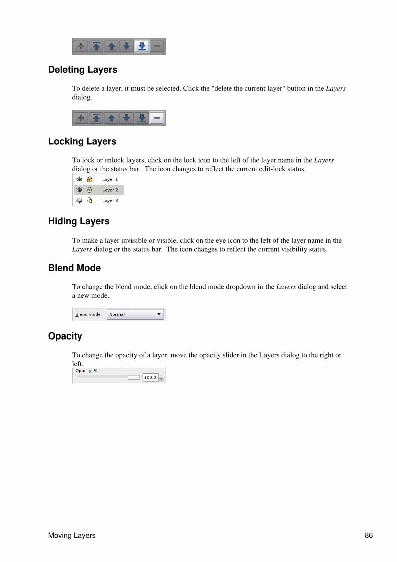
Deleting Layers
To delete a layer, it must be selected. Click the "delete the current layer" button in the Layersdialog.
Locking Layers
To lock or unlock layers, click on the lock icon to the left of the layer name in the Layersdialog or the status bar. The icon changes to reflect the current edit-lock status.
Hiding Layers
To make a layer invisible or visible, click on the eye icon to the left of the layer name in theLayers dialog or the status bar. The icon changes to reflect the current visibility status.
Blend Mode
To change the blend mode, click on the blend mode dropdown in the Layers dialog and selecta new mode.
Opacity
To change the opacity of a layer, move the opacity slider in the Layers dialog to the right orleft.
Moving Layers 86
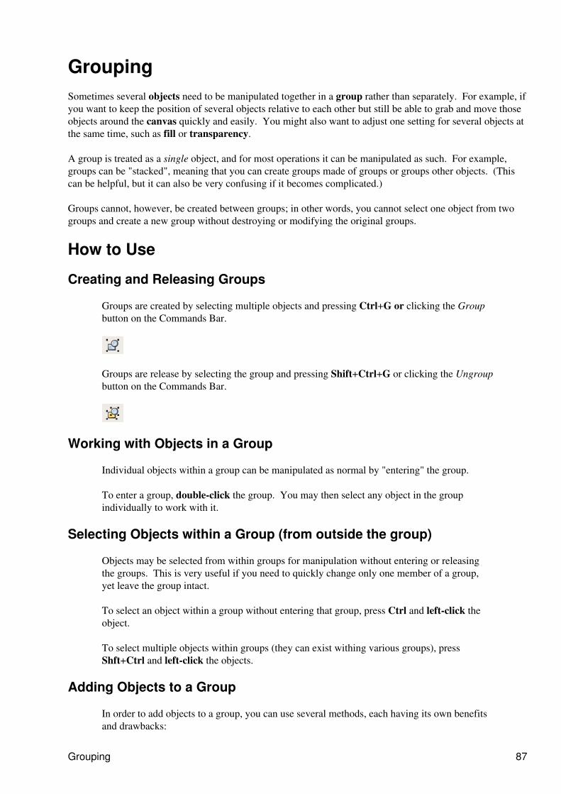
GroupingSometimes several objects need to be manipulated together in a group rather than separately. For example, ifyou want to keep the position of several objects relative to each other but still be able to grab and move thoseobjects around the canvas quickly and easily. You might also want to adjust one setting for several objects atthe same time, such as fill or transparency.
A group is treated as a single object, and for most operations it can be manipulated as such. For example,groups can be "stacked", meaning that you can create groups made of groups or groups other objects. (Thiscan be helpful, but it can also be very confusing if it becomes complicated.)
Groups cannot, however, be created between groups; in other words, you cannot select one object from twogroups and create a new group without destroying or modifying the original groups.
How to Use
Creating and Releasing Groups
Groups are created by selecting multiple objects and pressing Ctrl+G or clicking the Groupbutton on the Commands Bar.
Groups are release by selecting the group and pressing Shift+Ctrl+G or clicking the Ungroupbutton on the Commands Bar.
Working with Objects in a Group
Individual objects within a group can be manipulated as normal by "entering" the group.
To enter a group, double-click the group. You may then select any object in the groupindividually to work with it.
Selecting Objects within a Group (from outside the group)
Objects may be selected from within groups for manipulation without entering or releasingthe groups. This is very useful if you need to quickly change only one member of a group,yet leave the group intact.
To select an object within a group without entering that group, press Ctrl and left-click theobject.
To select multiple objects within groups (they can exist withing various groups), pressShft+Ctrl and left-click the objects.
Adding Objects to a Group
In order to add objects to a group, you can use several methods, each having its own benefitsand drawbacks:
Grouping 87

Select the group, ungroup, add the object to the selection, then regroup.1. Enter the group and draw a new object.2. Copy or cut the object from the canvas, enter the group, paste the object.3.
Adding Objects to a Group 88
Introduction to StylingObjects in SVG can have various types of styles applied to them, and Inkscape offers multiple approaches toapplying these styles. Unfortunately, this makes the discussion of styling objects fairly complex. Thischapter aims to simplify the discussion as much as possible while revealing the possibilities of Inkscape andSVG drawings. Accordingly, this introduction will focus on explaining the types of object styling and a littlebit about alternative ways of applying styles.
Fill
Fill is the visual content within the path borders of an SVG object. Each SVG object has some kind of fill(except diagram connectors). Note : Even bezier and freehand lines have fill, although by default it is set to transparent.
There are three basic types of fill:
Solid Fills - invariant color fills the object1. Gradient Fills - are a combination of two or more colors (or transparencies). A gradient begins withthe first color and blends smoothly into the next, etc. Gradients can either be linear or circular.
2.
Pattern Fills - are comprised of repeating images which can be selected from a preset or defined bythe user. They can be either paths and shapes or bitmaps.
3.
Stroke Paint
Stroke Paint is the visual content following the path borders of an SVG object.Each SVG object can have a stroke set or unset. Stroke Paint is basically the same as fill in that it can consistof solid colors, gradients or patterns. Stroke Width can be defined as well.
Stroke Width
Stroke Width is the thickness setting of an object's Stroke Paint.The center of an object's stroke follows the path of the object. For example, if the stroke is 10 pixels wide, thestroke will be drawn 5 pixels in opposite directions on either side of the path.
An interesting point: when stroke paint has partial transparency, the object's fill will show through the innerhalf of the stroke paint but not the outer half, since the path stops at the center of the stroke and bounds theobject's fill. This can either make for interesting drawing possibilities or frustrated artists. This is by SVGspecification design.
Application of Styles
Here is a description of methods of applying styles.
Copy Styles from Other Objects
If you want to copy styles from one object to another, you can do so easily by copying theobject as normal (press Ctrl+C) and then paste the style by pressing Shft+Ctrl+V.
Copy Dimensions from Other Objects
There are six options for copying dimensions from one object to a new object. They arefound in Edit > Paste Size
Introduction to Styling 89
Paste Size - paste both the copied height and width to the selected object(s) so that the wholeselection has the same dimensions as the original
Paste Width - paste only the copied width to the selected object(s) so that the whole selectionhas the same width as the original
Paste Height - paste only the copied height to the selected object(s) so that the wholeselection has the same height as the original
Paste Size Separately - paste the copied height and width to each selected object individually(when multiples are selected) so that each separate object within the selection has the sameheight and width as the original
Paste Width Separately - paste the copied width to each selected object individually (whenmultiples are selected) so that each separate object within the selection has the same width asthe original
Paste Height Separately - paste the copied height to each selected object individually (whenmultiples are selected) so that each separate object within the selection has the same height asthe original
Copy Dimensions from Other Objects 90
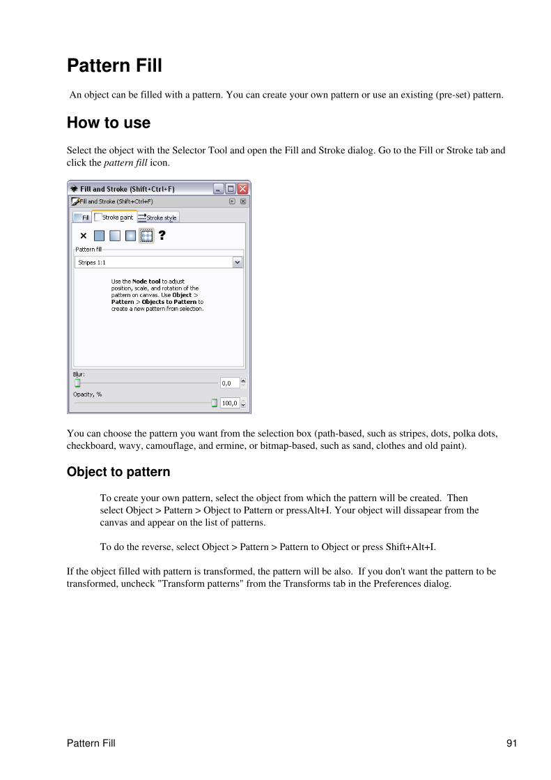
Pattern Fill An object can be filled with a pattern. You can create your own pattern or use an existing (pre-set) pattern.
How to use
Select the object with the Selector Tool and open the Fill and Stroke dialog. Go to the Fill or Stroke tab andclick the pattern fill icon.
You can choose the pattern you want from the selection box (path-based, such as stripes, dots, polka dots,checkboard, wavy, camouflage, and ermine, or bitmap-based, such as sand, clothes and old paint).
Object to pattern
To create your own pattern, select the object from which the pattern will be created. Thenselect Object > Pattern > Object to Pattern or pressAlt+I. Your object will dissapear from thecanvas and appear on the list of patterns.
To do the reverse, select Object > Pattern > Pattern to Object or press Shift+Alt+I.
If the object filled with pattern is transformed, the pattern will be also. If you don't want the pattern to betransformed, uncheck "Transform patterns" from the Transforms tab in the Preferences dialog.
Pattern Fill 91
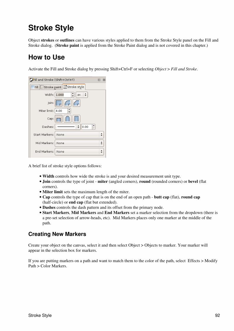
Stroke StyleObject strokes or outlines can have various styles applied to them from the Stroke Style panel on the Fill andStroke dialog. (Stroke paint is applied from the Stroke Paint dialog and is not covered in this chapter.)
How to Use
Activate the Fill and Stroke dialog by pressing Shift+Ctrl+F or selecting Object > Fill and Stroke.
A brief list of stroke style options follows:
Width controls how wide the stroke is and your desired measurement unit type.• Join controls the type of joint - miter (angled corners), round (rounded corners) or bevel (flatcorners).
•
Miter limit sets the maximum length of the miter.• Cap controls the type of cap that is on the end of an open path - butt cap (flat), round cap(half-circle) or end cap (flat but extended).
•
Dashes controls the dash pattern and its offset from the primary node.• Start Markers, Mid Markers and End Markers set a marker selection from the dropdown (there isa pre-set selection of arrow-heads, etc). Mid Markers places only one marker at the middle of thepath.
•
Creating New Markers
Create your object on the canvas, select it and then select Object > Objects to marker. Your marker willappear in the selection box for markers.
If you are putting markers on a path and want to match them to the color of the path, select Effects > ModifyPath > Color Markers.
Stroke Style 92
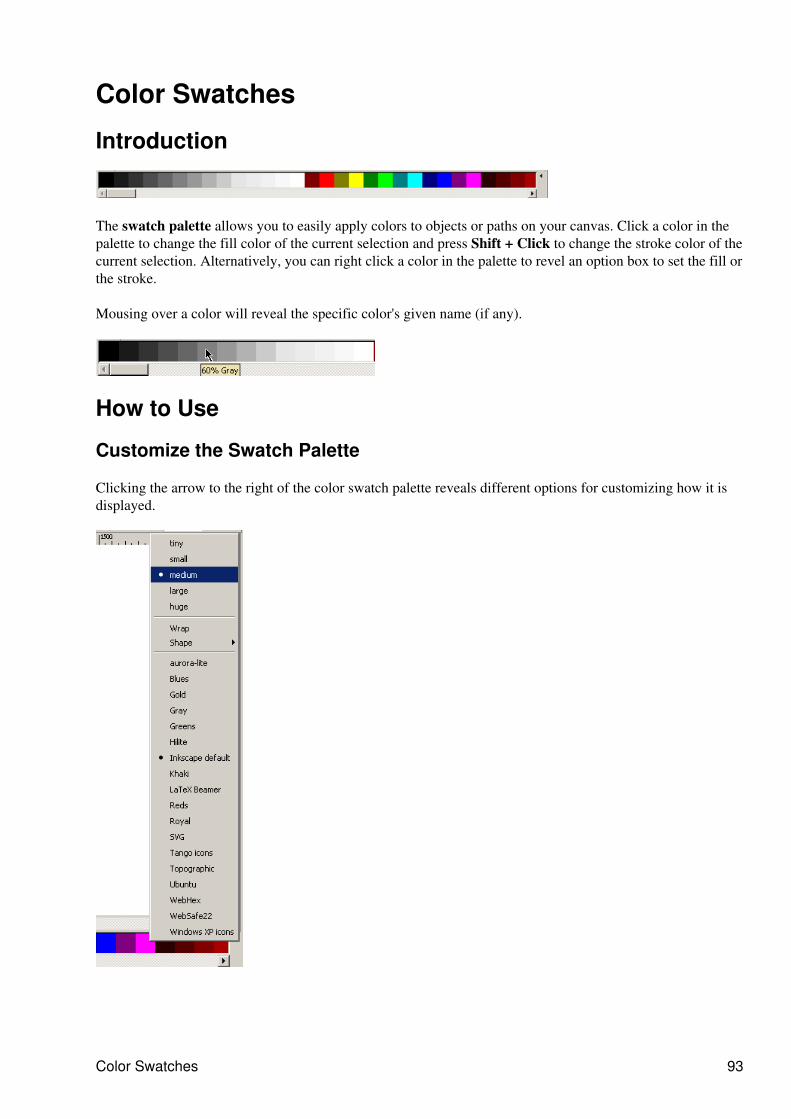
Color Swatches
Introduction
The swatch palette allows you to easily apply colors to objects or paths on your canvas. Click a color in thepalette to change the fill color of the current selection and press Shift + Click to change the stroke color of thecurrent selection. Alternatively, you can right click a color in the palette to revel an option box to set the fill orthe stroke.
Mousing over a color will reveal the specific color's given name (if any).
How to Use
Customize the Swatch Palette
Clicking the arrow to the right of the color swatch palette reveals different options for customizing how it isdisplayed.
Color Swatches 93
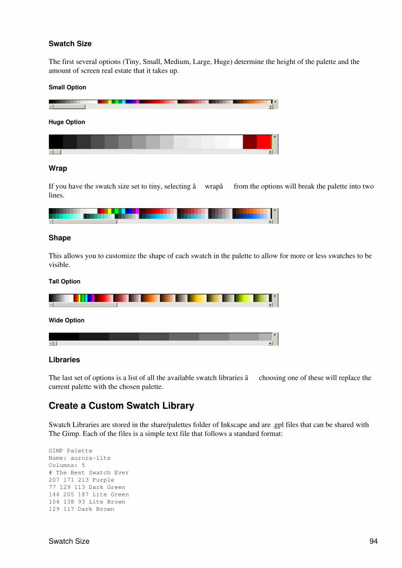
Swatch Size
The first several options (Tiny, Small, Medium, Large, Huge) determine the height of the palette and theamount of screen real estate that it takes up.
Small Option
Huge Option
Wrap
If you have the swatch size set to tiny, selecting �wrap� from the options will break the palette into twolines.
Shape
This allows you to customize the shape of each swatch in the palette to allow for more or less swatches to bevisible.
Tall Option
Wide Option
Libraries
The last set of options is a list of all the available swatch libraries � choosing one of these will replace thecurrent palette with the chosen palette.
Create a Custom Swatch Library
Swatch Libraries are stored in the share/palettes folder of Inkscape and are .gpl files that can be shared withThe Gimp. Each of the files is a simple text file that follows a standard format:
GIMP PaletteName: aurora-liteColumns: 5# The Best Swatch Ever207 171 213 Purple77 129 113 Dark Green144 205 187 Lite Green154 138 93 Lite Brown129 117 Dark Brown
Swatch Size 94
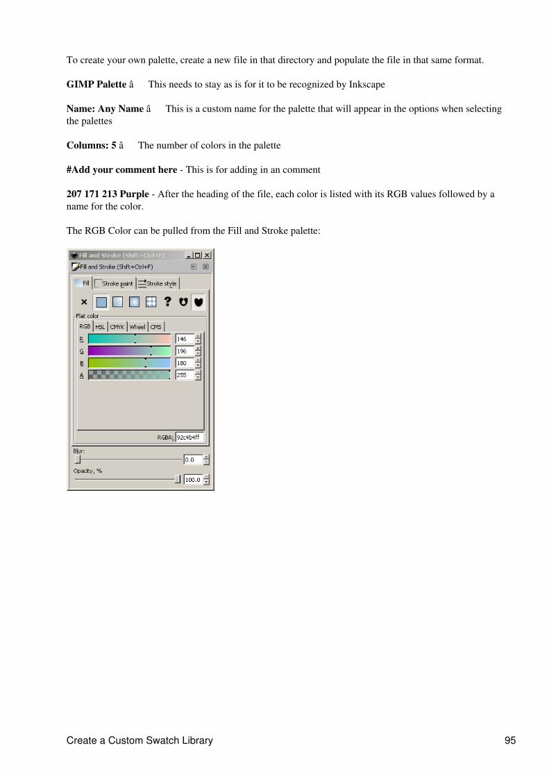
To create your own palette, create a new file in that directory and populate the file in that same format.
GIMP Palette � This needs to stay as is for it to be recognized by Inkscape
Name: Any Name � This is a custom name for the palette that will appear in the options when selectingthe palettes
Columns: 5 � The number of colors in the palette
#Add your comment here - This is for adding in an comment
207 171 213 Purple - After the heading of the file, each color is listed with its RGB values followed by aname for the color.
The RGB Color can be pulled from the Fill and Stroke palette:
Create a Custom Swatch Library 95
Live Path EffectsLive path effects (not to be confused with Extension Effects or SVG Filters) are a new way tonon-destructively modify path and shape objects. Path Effects affect the path data of an object but not itsstyle. The original path is preserved and can be edited directly on canvas, and the path effect applied to it willbe updated live.
In the version 0.46 several path effects that are analogous to the corresponding extension effects (such as Pathalong Path effect and Pattern along Path that replaces the extension of the same name) are included. Themost important advantage of path effects is that they are, indeed, live � you can still edit the original pathand the effect will update in real time (unlike the extension effects which were one-time one-waytransformations).
Details about operation
The following schematic tries to explain how LPE work.
original style ------------> output style original path --> LPE --> output path ^ | parameters
The original style and path are from the path that the effect is applied on. The output is what is visible onscreen. What is very important to notice is that output style equals original style.
The parameters can be paths, numbers, points, text, in principle anything.
Applying effects
Path effects are applied through the Path Effects dialog. This is opened from the Path menu, or by pressingCtrl +Shift +7. This dialog is also used for controlling the effect's parameters and for removing effects.
When a path with a path effect applied is selected, the statusbar description gives details, for example "Path(4 nodes, path effect)".
There is a special Paste Path Effect command Ctrl+ 7 that can be used to copy effects from one path toanother.
Editing effect parameters
When switching to the Node Edit tool F2, the original path can be edited. The original path is shown as a redhelper path. Normal path operations, like simplify, still work.
Some parameters of these effects can be edited on-canvas. For example, path parameters can be node-edited,by pressing the edit on-canvas button in the Path Effects dialog. Press 7 to cycle through the differenton-canvas editable parameters. This way, one can edit the parameters without opening the Path Effects dialog.The statusbar tells the name of the parameters that is currently being shown.
Live Path Effects 96

Available effects
Currently available live path effects are:
Bend• Pattern along path• Stitch subpaths• Gears•
Development of new effects
One of the goals of the Summer of Code project was to make it easy to create new effects. There is aframework that greatly simplifies effect implementation; very little code is needed to get the effect hookedinto Inkscape. This leaves valuable time for the actual effect to be implemented. See thehttp://wiki.inkscape.org/wiki/index.php/MakingLivePathEffects wiki page for an explanation of how to getstarted with your own effect!
Available effects 97
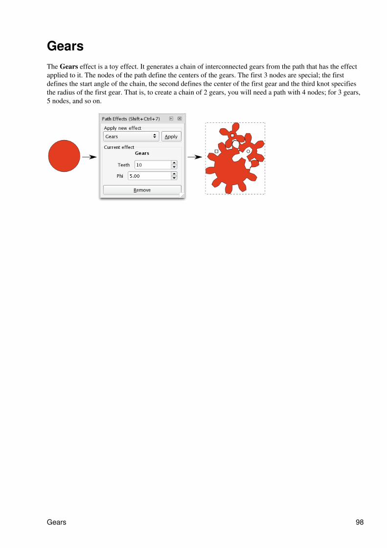
GearsThe Gears effect is a toy effect. It generates a chain of interconnected gears from the path that has the effectapplied to it. The nodes of the path define the centers of the gears. The first 3 nodes are special; the firstdefines the start angle of the chain, the second defines the center of the first gear and the third knot specifiesthe radius of the first gear. That is, to create a chain of 2 gears, you will need a path with 4 nodes; for 3 gears,5 nodes, and so on.
Gears 98
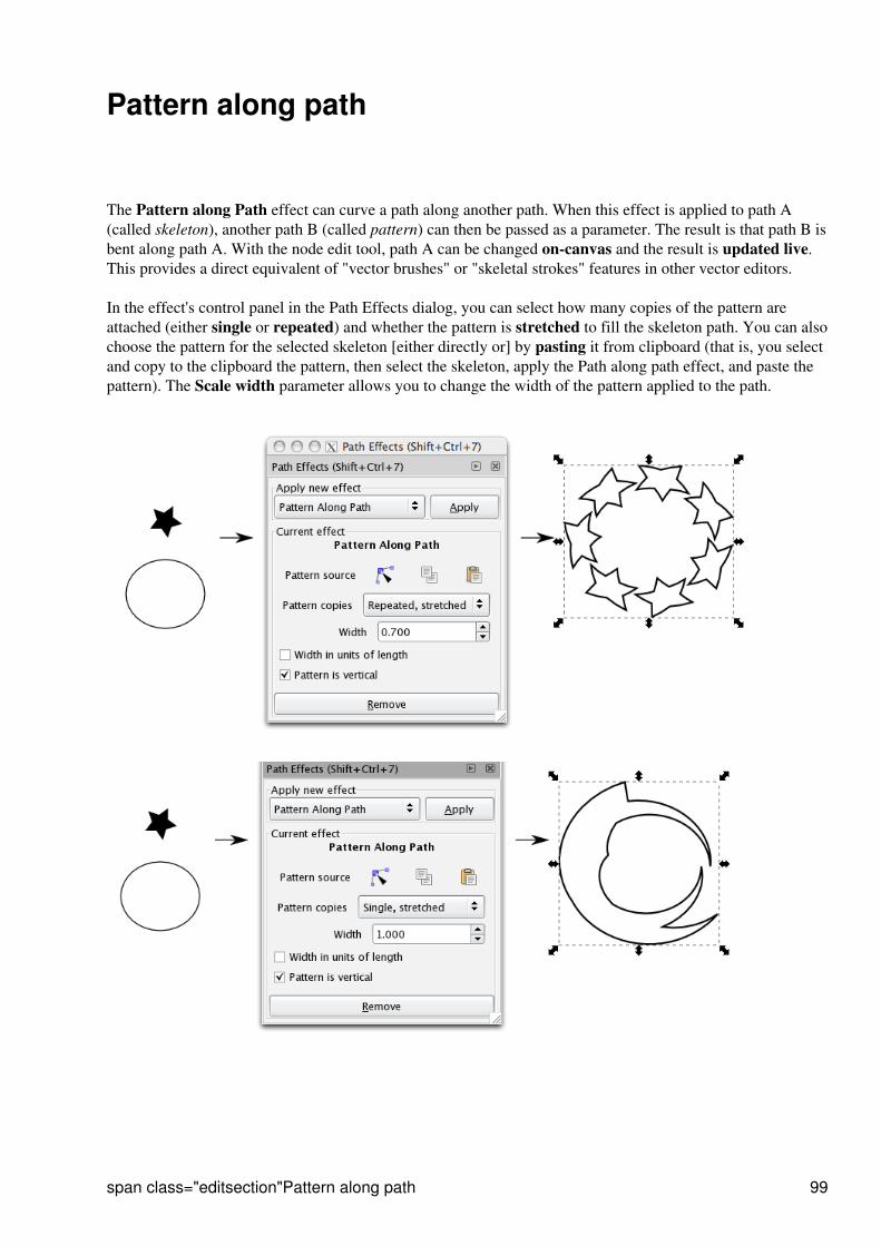
Pattern along path
The Pattern along Path effect can curve a path along another path. When this effect is applied to path A(called skeleton), another path B (called pattern) can then be passed as a parameter. The result is that path B isbent along path A. With the node edit tool, path A can be changed on-canvas and the result is updated live.This provides a direct equivalent of "vector brushes" or "skeletal strokes" features in other vector editors.
In the effect's control panel in the Path Effects dialog, you can select how many copies of the pattern areattached (either single or repeated) and whether the pattern is stretched to fill the skeleton path. You can alsochoose the pattern for the selected skeleton [either directly or] by pasting it from clipboard (that is, you selectand copy to the clipboard the pattern, then select the skeleton, apply the Path along path effect, and paste thepattern). The Scale width parameter allows you to change the width of the pattern applied to the path.
span class="editsection"Pattern along path 99
Introduction to SVG Filter Effects
Basics
SVG filters are different from e.g. GIMP filters in a sense that what counts in GIMP for a filter in SVG is afilter primitive. And a filter in SVG can contain multiple primitives. For example, an SVG filter that createsan effect of fire consistes of Turbulence, Color Matrix and Gaussian blur primitives. SVG filters are alsonon-destructive in its nature and canbe applied to both vector and bitmap objects of an SVG document.
What should be taken into consideration all the time is that SVG Filters always deal with bitmaprepresentation of vector graphics. A filter either makes a momentary snapshot of all data below it, or instantlyreapplies changes to underlying bitmap representation of an image when it changes.
Filter primitives
Inkscape supports the following SVG filter proimitives:
The feBlend filter primitive gives us image blending modes, like in many image manipulationprograms. These modes are screen, multiply, darken and lighten. There's a caveat, though: whenblending an object against an semi-transparent background, the background will be accumulatedtwice, resulting in thicker objects under the bounding box of blended object. This is a limitation ofcurrent version of SVG format, not a bug in Inkscape.
•
The feColorMatrix filter primitive applies a matrix transformation to colour of each rendered pixel.This allows for effects like turning object to grayscale, modifying colour saturation and changingcolour hue.
•
The feComposite filter primitive composites two images using one of the Porter-Duff blendingmodes (described in paper Compositing Digital Images by T. Porter and T. Duff, published inSIGGRAPH '84 Conference Proceedings, Association for Computing Machinery, Volume 18,Number 3, July 1984) or the aritmetic mode described in SVG standard. Porter-Duff blending modesare essentially logical operations between the images. For example, xor mode shows the areas, whereeither one of the objects is, but not the areas where both of the objects are. Arithmetic mode lets youspecify coefficients k1-k4 for blending equation (result colour) = k1 * (first input colour) * (secondinput colour) + k2 * (first input colour) + k3 * (second input colour) + k4.
•
The feConvolveMatrix lets you specify a Convolution to be applied on the image. Common effectscreated using convolution matrices are blur, sharpening, embossing and edge detection. There's afairly good explanation and some example matrices atwww.gamedev.net/reference/programming/features/imageproc/page2.asp. Note that while gaussianblur can be created using this filter primitive, the special gaussian blur primitive is faster andresolution-independent.
•
Filter primitives feDiffuseLighting and feSpecularLighting create lighting maps for the object ininput image. SVG doesn't have concept of third dimension, so these filters use alpha channel of inputimage as a height map: the more opaque given point in input image is, the nearer spectator it isconsidered to be. There exists an example for using these in Inkscape distribution, inshare/examples/lighting_effects.svg.
•
The feDisplacementMap filter primitive displaces the pixels in the first input using the second inputas a displacement map, that shows from how far the pixel should come from. Classical examples arewhirl and pinch effects, that can be found in most image manipulation programs and even in somescreensavers, where this kind off effect is moving around screen, twisting desktop beneath it.
•
Introduction to SVG Filter Effects 100
The feFlood filter primitive fills its region with a given color and opacity. It can be used as anauxiliary tool, usualy in combination with other filter primitives, in order to facilitate some commoncolor handling operations.
•
The feGaussianBlur filter primitive allows natural blurring any Inkscape objects: paths, shapes,groups, text, images. Gaussian blur enables a wide range of photorealistic effects: arbitrarily shapedshades and lights, depth of field, drop shadows, glows, etc. Also, blurred objects can be used as masksfor other objects to achieve the "feathered mask" effect.
The feImage filter primitive allows using external images as part of filtering chain. For example, onecould use external image as a displacement map for feDisplacementMap or as a height map forlighting effects. Note that while SVG standard allows using other parts of the SVG file in this filterprimitive, the current Inkscape implementation only allows external images.
•
The feMerge filter primitive composites several temporary images inside the filter primitive to asingle image. It uses normal alpha compositing for this. This is equivalent to using several feBlendprimitives in 'normal' mode or several feComposite primitives in 'over' -mode.
•
The feMorphology filter primitive provides erode and dilate effects, that are common in imagemanipulation programs. With erode, darker and more transparent areas spread to lighter and moreopaque areas, whereas with dilate lighter and more opaque areas spread to darker and moretransparent areas. For single-colour objects, this basically means, erode makes the object thinner anddilate makes it thicker.
•
The feOffset filter primitive offsets the image by an user-defined amount. For example, this is usefulfor drop shadows, where the shadow is in a slightly different position than the actual object.
•
The feTurbulence filter primitive renders Perlin noise. This kind of noise is useful in simulatingseveral nature phenomena like clouds, fire and smoke and in generating complex textures like marbleor granite.
•
Filter UI
Parts of the dialog
Creating and modifying filter effects is done in a dedicated dialog Object>Filter Effects....
Filter primitives 101
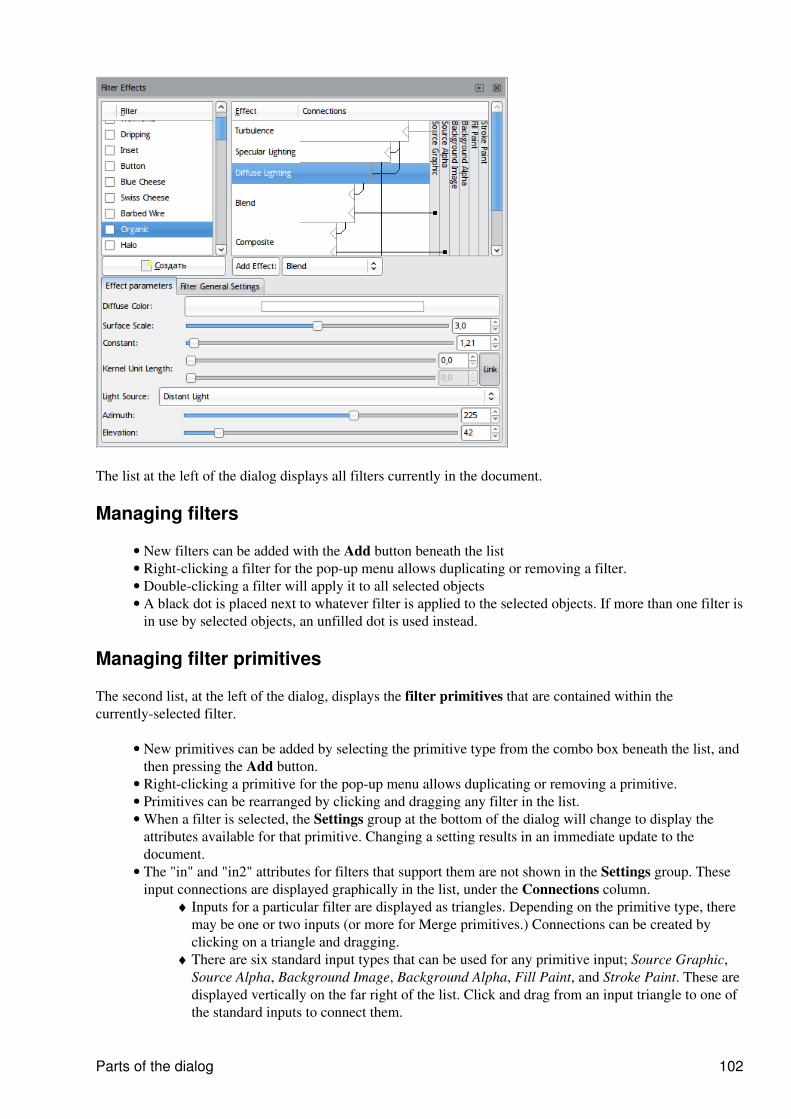
The list at the left of the dialog displays all filters currently in the document.
Managing filters
New filters can be added with the Add button beneath the list• Right-clicking a filter for the pop-up menu allows duplicating or removing a filter.• Double-clicking a filter will apply it to all selected objects• A black dot is placed next to whatever filter is applied to the selected objects. If more than one filter isin use by selected objects, an unfilled dot is used instead.
•
Managing filter primitives
The second list, at the left of the dialog, displays the filter primitives that are contained within thecurrently-selected filter.
New primitives can be added by selecting the primitive type from the combo box beneath the list, andthen pressing the Add button.
•
Right-clicking a primitive for the pop-up menu allows duplicating or removing a primitive.• Primitives can be rearranged by clicking and dragging any filter in the list.• When a filter is selected, the Settings group at the bottom of the dialog will change to display theattributes available for that primitive. Changing a setting results in an immediate update to thedocument.
•
The "in" and "in2" attributes for filters that support them are not shown in the Settings group. Theseinput connections are displayed graphically in the list, under the Connections column.
Inputs for a particular filter are displayed as triangles. Depending on the primitive type, theremay be one or two inputs (or more for Merge primitives.) Connections can be created byclicking on a triangle and dragging.
♦
There are six standard input types that can be used for any primitive input; Source Graphic,Source Alpha, Background Image, Background Alpha, Fill Paint, and Stroke Paint. These aredisplayed vertically on the far right of the list. Click and drag from an input triangle to one ofthe standard inputs to connect them.
♦
•
Parts of the dialog 102

Primitives can also be connected to other primitives by clicking an input triangle anddragging upwards to another primitive. A primitive can only be connected to one higher upthe list.
♦
Single-clicking on an input triangle will unset it, returning it to the default. If it is on a Mergeprimitive, the input will be deleted.
♦
Merge inputs have an empty input at the end. Dragging a connection from this input will adda new input to the primitive.
♦
Managing filter primitives 103
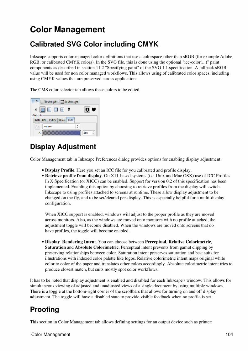
Color Management
Calibrated SVG Color including CMYK
Inkscape supports color-managed color definitions that use a colorspace other than sRGB (for example AdobeRGB, or calibrated CMYK colors). In the SVG file, this is done using the optional "icc-color(...)" paintcomponents as described in section 11.2 "Specifying paint" of the SVG 1.1 specification. A fallback sRGBvalue will be used for non color managed workflows. This allows using of calibrated color spaces, includingusing CMYK values that are preserved across applications.
The CMS color selector tab allows these colors to be edited.
Display Adjustment
Color Management tab in Inkscape Preferences dialog provides options for enabling display adjustment:
Display Profile. Here you set an ICC file for you calibrated and profile display.• Retrieve profile from display. On X11-based systems (i.e. Unix and Mac OSX) use of ICC ProfilesIn X Specification (or XICC) can be enabled. Support for version 0.2 of this specification has beenimplemented. Enabling this option by choosing to retrieve profiles from the display will switchInkscape to using profiles attached to screens at runtime. These allow display adjustment to bechanged on the fly, and to be set/cleared per-display. This is especially helpful for a multi-displayconfiguration.
•
When XICC support is enabled, windows will adjust to the proper profile as they are movedacross monitors. Also, as the windows are moved onto monitors with no profile attached, theadjustment toggle will become disabled. When the windows are moved onto screens that dohave profiles, the toggle will become enabled.
Display Rendering Intent. You can choose between Perceptual, Relative Colorimetric,Saturation and Absolute Colorimetric. Perceptual intent prevents from gamut clipping bypreserving relationships between color. Saturation intent preserves saturation and best suits forillustrations with indexed color palette like logos. Relative colorimetric intent maps original whitecolor to color of the paper and translates other colors accordingly. Absolute colorimetric intent tries toproduce closest match, but suits mostly spot color workflows.
•
It has to be noted that display adjustment is enabled and disabled for each Inkscape's window. This allows forsimultaneous viewing of adjusted and unadjusted views of a single document by using multiple windows.There is a toggle at the bottom-right corner of the scrollbars that allows for turning on and off displayadjustment. The toggle will have a disabled state to provide visible feedback when no profile is set.
Proofing
This section in Color Management tab allows defining settings for an output device such as printer:
Color Management 104

Simulate output on screen option enables softproofing, that is � the document will look exactly asit will be outputted to printer.
•
Mark out of gamut colors. All devices have a unique set of colors (gamut) they can reproduce, be ita display or a printer. This option enables marking the colors that cannot be reproduced in destinationcolor space witha user defined color. By default neutral grey color is used.
•
Device profile. This is an ICC profile for the output device (usually, a printer). For Europe theEuroscale Uncoated v2 profile is recommended to be used by default, and for USA � U.S. WebCoated (SWOP) v2 or U.S. Sheet-fed Coated v2.
•
Device Rendering Intent. You can choose between Perceptual, Relative Colorimetric, Saturation andAbsolute Colorimetric.
•
Black Point Compensation. BPC's primary function is to map dynamic range of an image todynamic range of an output device, so that contrast us not lost. It is usually used for publications witha lot of full color graphics like photos. Note that BPC is used only with relative colorimetric renderingintent and should be disabled for other rendering intent types.
•
Preserve Black. Makes Inkscape do its best to provide same level of blackness in the output.•
Operation Systems Support
Сolor management is supported in Linux and Mac OS X only inthe current stable version of Inkscape.
Creating ICC Profiles
For creating ICC profiles with free software LProf and ArgyllCMS are recommended.
Proofing 105
Generate TemplateThe only available extension to create a template right now is Perfect-Bound Cover which modifies thedocument to create a cover for perfect-bound books using US size and paper weight measurements. Thisextension will resize the document to include the width, height, spine width, and bleed measurements that areprovided to the extensions, so it should be the first operation done before designing.
Ideally, you want to know the PPI of the paper stock you�ll be using. Average caliper size or point size(which is the caliper size times 1000) are just as good. Your printer should be able to tell you any of thesemeasurements. If not, you�ll have to guess. Or find another printer. If you don�t know the PPI, caliper,or point size of the paper your printer is using, but do know the type of paper and its weight, you canestimate PPI or caliper using the charts on the Case Paper (http://www.casepaper.com/calc_chart_caliper.htm ) or the Micro Format (http://www.paper-paper.com/weight.html ) site.
For instance, let�s say your printer uses 20# bond paper, a pretty standard paper weight, to print theinterior pages of your 200 page book. Most likely, the caliper size of this paper is .004, but again, verify thiswith your printer before proceeding. Calculate the PPI by diving the number 2 by the caliper size:
2/.004 = 500
The PPI of this paper is 500, which means that, for every 500 pages in your book, the spine will be 1 inchthick.
Now, with the PPI, you can calculate the thickness of the spine, without the allowance for the cover. The sizeof the spine for the interior pages will be:
200/500 = .4 inches
Next, do the same for the cover. Let�s say your cover is going to be printed on 9pt paper stock. Points tocaliper is a really easy conversion � divide the points by 1000 to get .009, then calculate:
2/.009 = 222
Since the cover is four �pages� (outside and inside covers), the additional inches you need to add to thespine will be:
4/222 = .018
So your final spine width in inches for a 200 page book printed on 20# bond with a cover that is printed on 9ptstock is:
(200 / (2/.004)) + (4 / (2/.009)) = .418
.4 + .018 = .418 inches
All this is different in metric.
Let's take an example. You have a 6�x9� book with 176 pages to be printed on paper with a PPI of 426and the cover � on 9pt stock. You also need 1/8� bleeds. Here�s how you would set up the document:
Generate Template 106
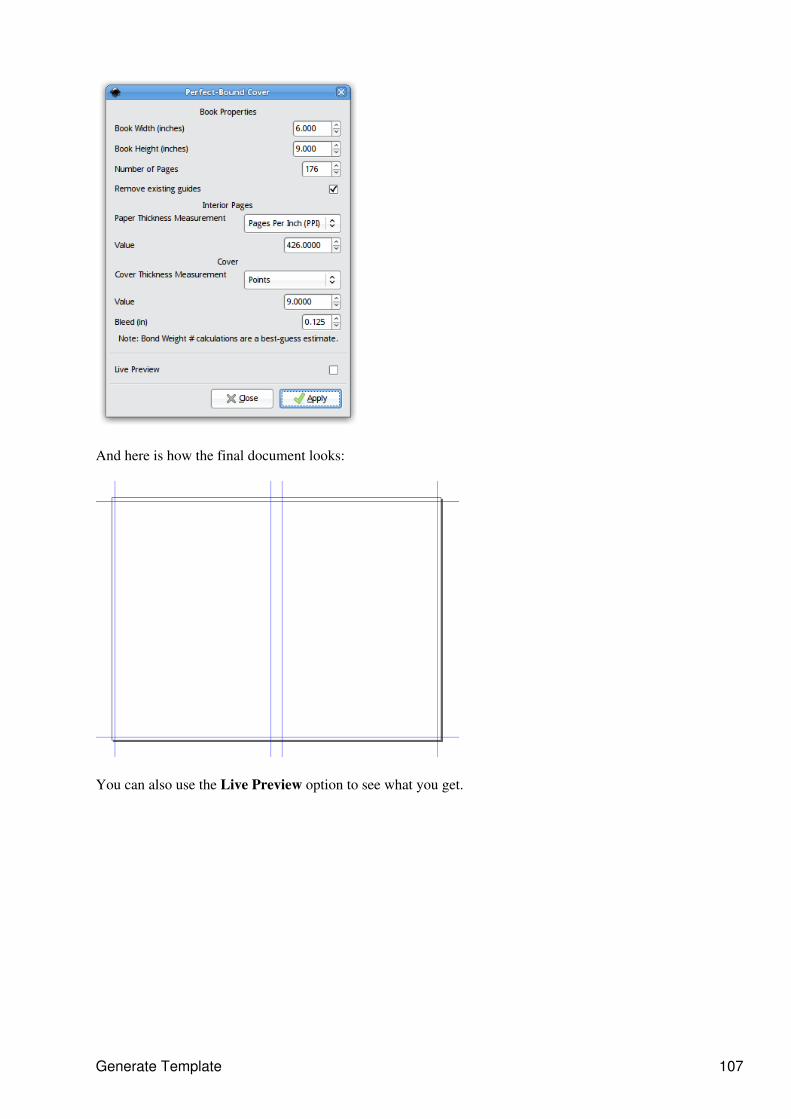
And here is how the final document looks:
You can also use the Live Preview option to see what you get.
Generate Template 107
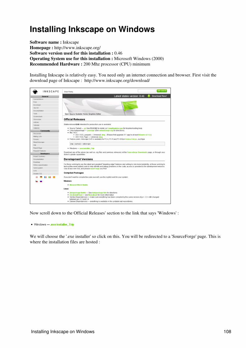
Installing Inkscape on WindowsSoftware name : InkscapeHomepage : http://www.inkscape.org/Software version used for this installation : 0.46Operating System use for this installation : Microsoft Windows (2000)Recommended Hardware : 200 Mhz processor (CPU) minimum
Installing Inkscape is relatively easy. You need only an internet connection and browser. First visit thedownload page of Inkscape : http://www.inkscape.org/download/
Now scroll down to the Official Releases' section to the link that says 'Windows' :
We will choose the '.exe installer' so click on this. You will be redirected to a 'SourceForge' page. This iswhere the installation files are hosted :
Installing Inkscape on Windows 108
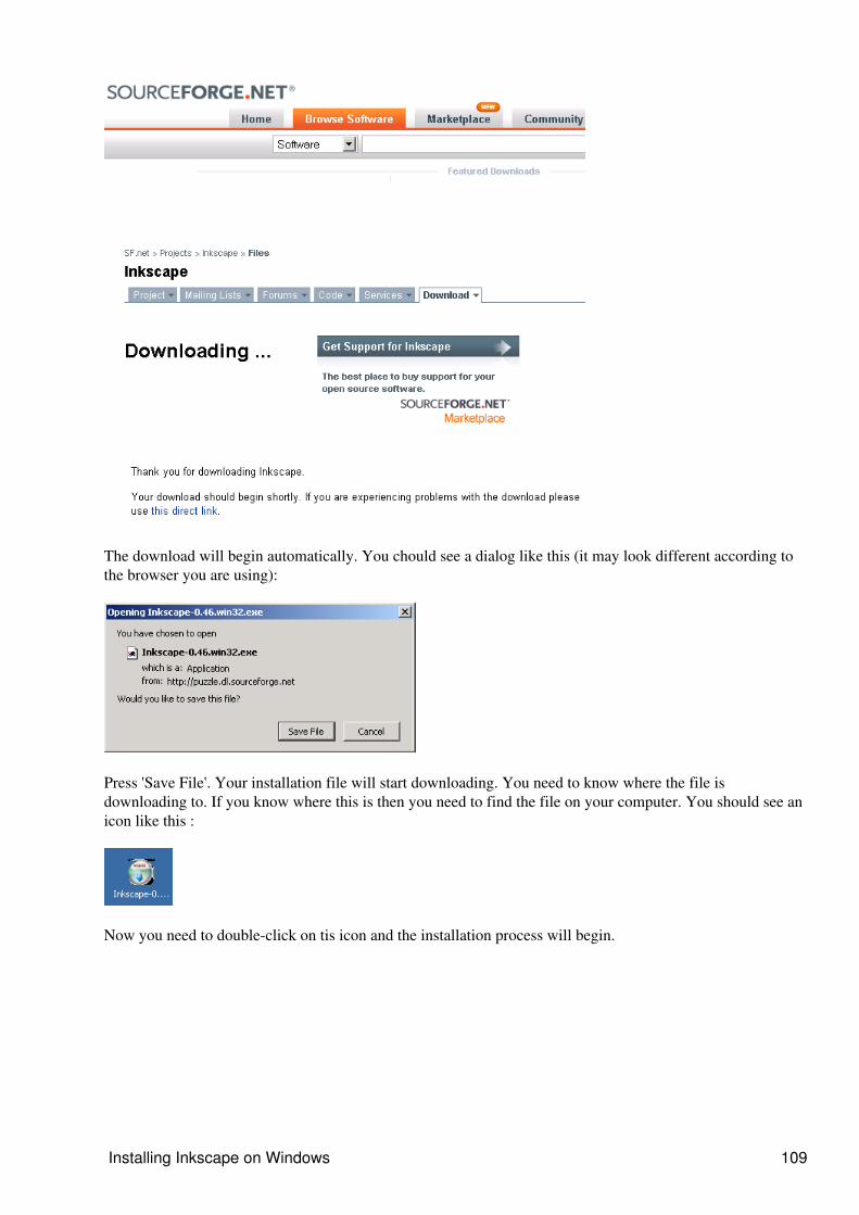
The download will begin automatically. You chould see a dialog like this (it may look different according tothe browser you are using):
Press 'Save File'. Your installation file will start downloading. You need to know where the file isdownloading to. If you know where this is then you need to find the file on your computer. You should see anicon like this :
Now you need to double-click on tis icon and the installation process will begin.
Installing Inkscape on Windows 109
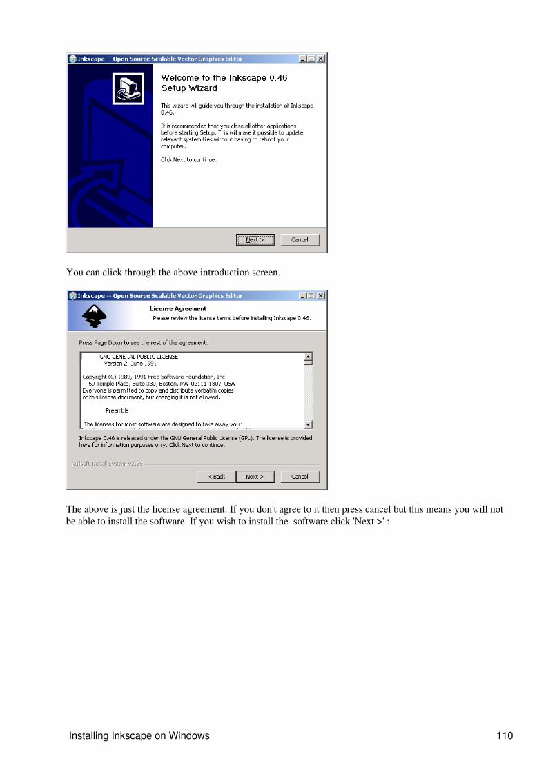
You can click through the above introduction screen.
The above is just the license agreement. If you don't agree to it then press cancel but this means you will notbe able to install the software. If you wish to install the software click 'Next >' :
Installing Inkscape on Windows 110
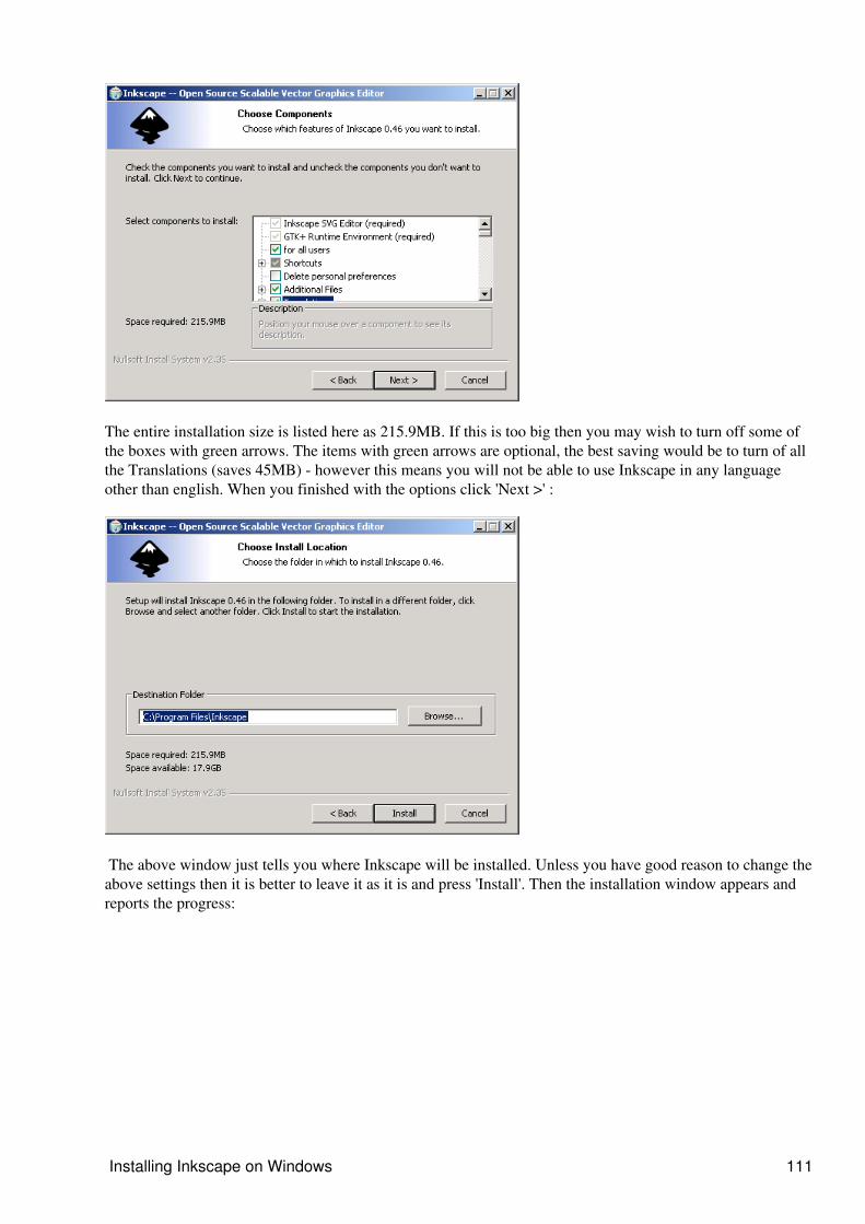
The entire installation size is listed here as 215.9MB. If this is too big then you may wish to turn off some ofthe boxes with green arrows. The items with green arrows are optional, the best saving would be to turn of allthe Translations (saves 45MB) - however this means you will not be able to use Inkscape in any languageother than english. When you finished with the options click 'Next >' :
The above window just tells you where Inkscape will be installed. Unless you have good reason to change theabove settings then it is better to leave it as it is and press 'Install'. Then the installation window appears andreports the progress:
Installing Inkscape on Windows 111
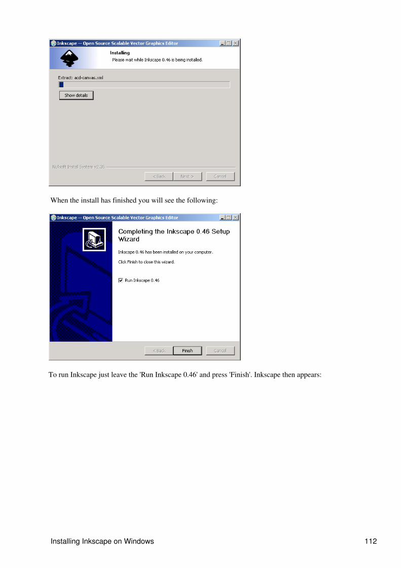
When the install has finished you will see the following:
To run Inkscape just leave the 'Run Inkscape 0.46' and press 'Finish'. Inkscape then appears:
Installing Inkscape on Windows 112
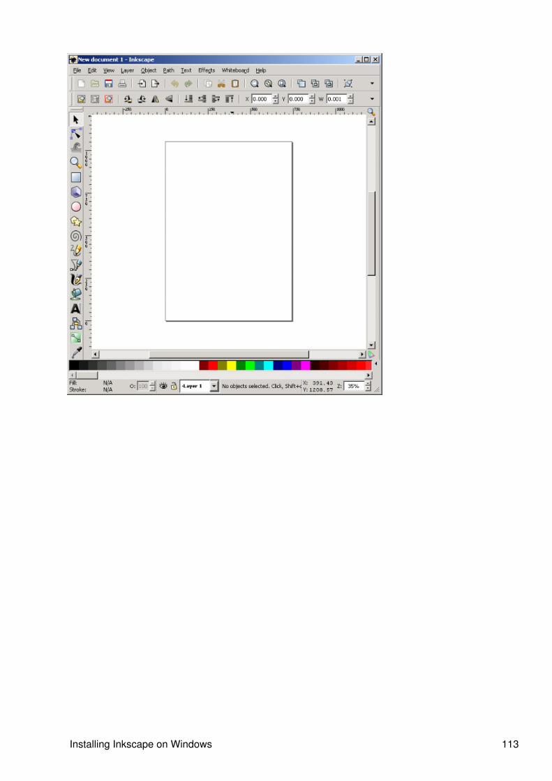
Installing Inkscape on Windows 113
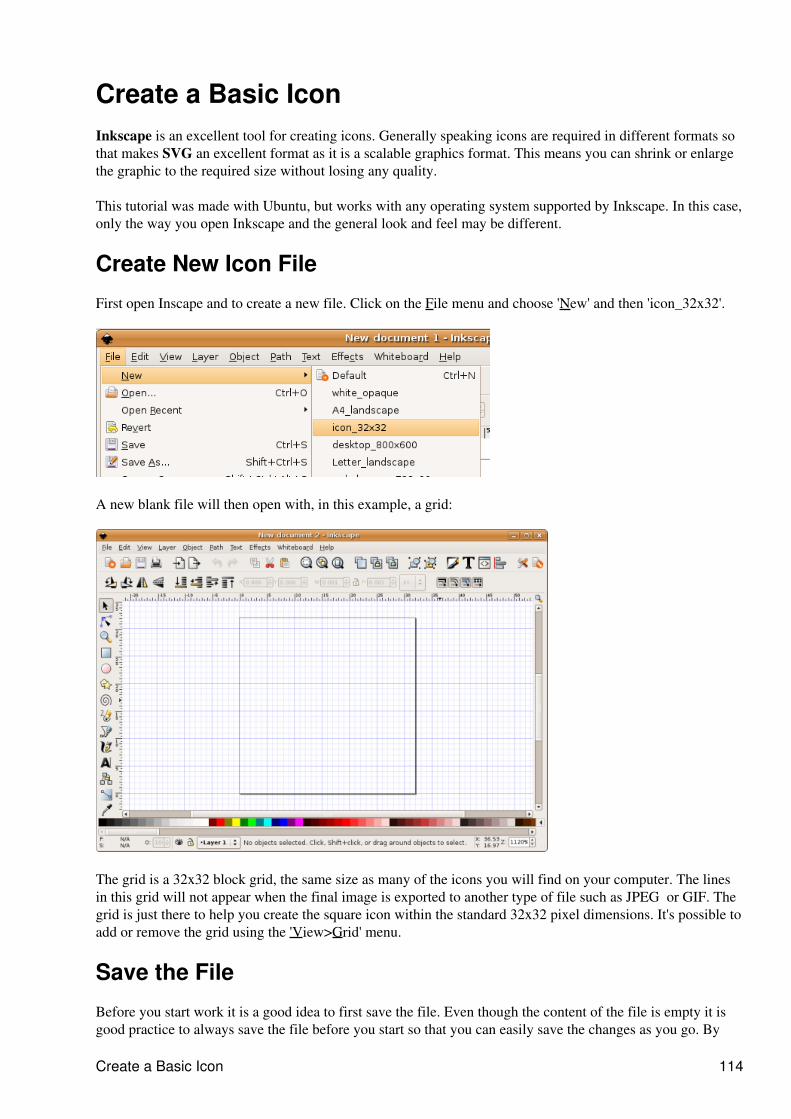
Create a Basic IconInkscape is an excellent tool for creating icons. Generally speaking icons are required in different formats sothat makes SVG an excellent format as it is a scalable graphics format. This means you can shrink or enlargethe graphic to the required size without losing any quality.
This tutorial was made with Ubuntu, but works with any operating system supported by Inkscape. In this case,only the way you open Inkscape and the general look and feel may be different.
Create New Icon File
First open Inscape and to create a new file. Click on the File menu and choose 'New' and then 'icon_32x32'.
A new blank file will then open with, in this example, a grid:
The grid is a 32x32 block grid, the same size as many of the icons you will find on your computer. The linesin this grid will not appear when the final image is exported to another type of file such as JPEG or GIF. Thegrid is just there to help you create the square icon within the standard 32x32 pixel dimensions. It's possible toadd or remove the grid using the 'View>Grid' menu.
Save the File
Before you start work it is a good idea to first save the file. Even though the content of the file is empty it isgood practice to always save the file before you start so that you can easily save the changes as you go. By
Create a Basic Icon 114
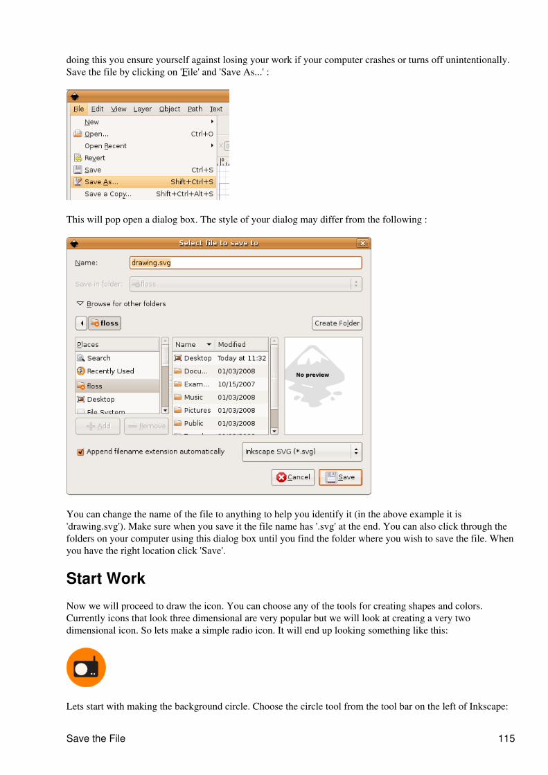
doing this you ensure yourself against losing your work if your computer crashes or turns off unintentionally.Save the file by clicking on 'File' and 'Save As...' :
This will pop open a dialog box. The style of your dialog may differ from the following :
You can change the name of the file to anything to help you identify it (in the above example it is'drawing.svg'). Make sure when you save it the file name has '.svg' at the end. You can also click through thefolders on your computer using this dialog box until you find the folder where you wish to save the file. Whenyou have the right location click 'Save'.
Start Work
Now we will proceed to draw the icon. You can choose any of the tools for creating shapes and colors.Currently icons that look three dimensional are very popular but we will look at creating a very twodimensional icon. So lets make a simple radio icon. It will end up looking something like this:
Lets start with making the background circle. Choose the circle tool from the tool bar on the left of Inkscape:
Save the File 115
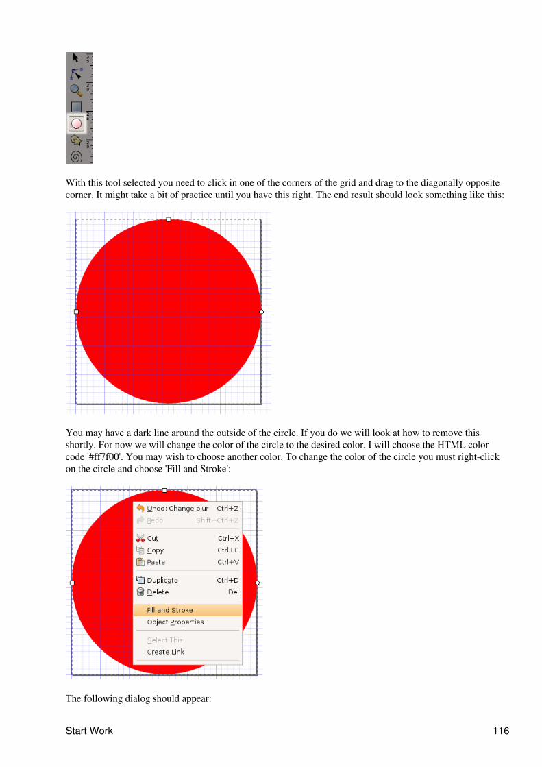
With this tool selected you need to click in one of the corners of the grid and drag to the diagonally oppositecorner. It might take a bit of practice until you have this right. The end result should look something like this:
You may have a dark line around the outside of the circle. If you do we will look at how to remove thisshortly. For now we will change the color of the circle to the desired color. I will choose the HTML colorcode '#ff7f00'. You may wish to choose another color. To change the color of the circle you must right-clickon the circle and choose 'Fill and Stroke':
The following dialog should appear:
Start Work 116
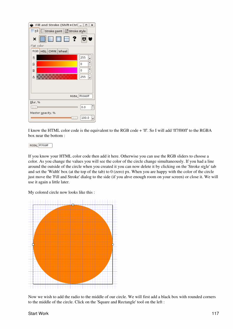
I know the HTML color code is the equivalent to the RGB code + 'ff'. So I will add 'ff7f00ff' to the RGBAbox near the bottom :
If you know your HTML color code then add it here. Otherwise you can use the RGB sliders to choose acolor. As you change the values you will see the color of the circle change simultaneously. If you had a linearound the outside of the circle when you created it you can now delete it by clicking on the 'Stroke style' taband set the 'Width' box (at the top of the tab) to 0 (zero) px. When you are happy with the color of the circlejust move the 'Fill and Stroke' dialog to the side (if you ahve enough room on your screen) or close it. We willuse it again a little later.
My colored circle now looks like this :
Now we wish to add the radio to the middle of our circle. We will first add a black box with rounded cornersto the middle of the circle. Click on the 'Square and Rectangle' tool on the left :
Start Work 117
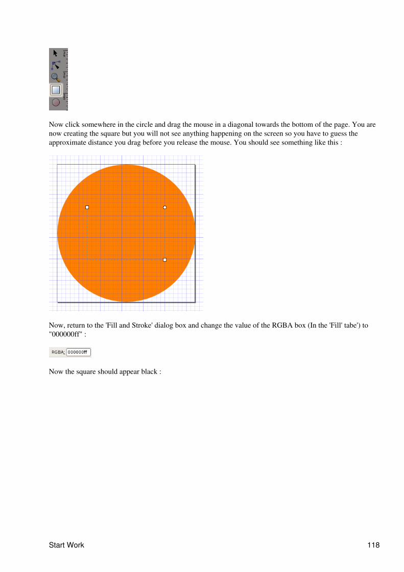
Now click somewhere in the circle and drag the mouse in a diagonal towards the bottom of the page. You arenow creating the square but you will not see anything happening on the screen so you have to guess theapproximate distance you drag before you release the mouse. You should see something like this :
Now, return to the 'Fill and Stroke' dialog box and change the value of the RGBA box (In the 'Fill' tabe') to"000000ff" :
Now the square should appear black :
Start Work 118
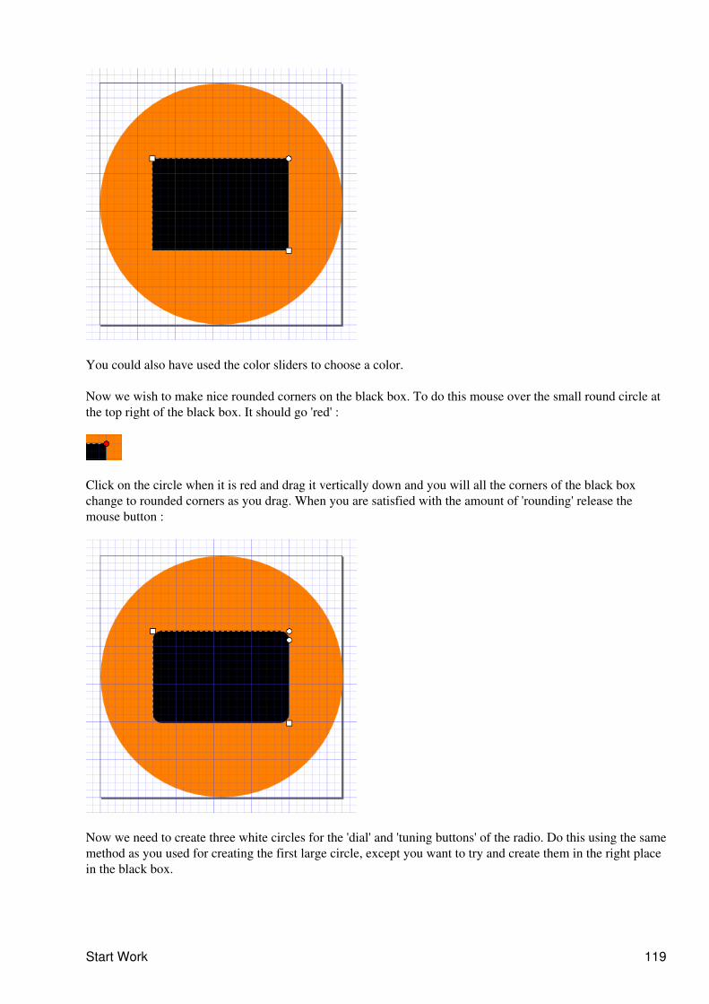
You could also have used the color sliders to choose a color.
Now we wish to make nice rounded corners on the black box. To do this mouse over the small round circle atthe top right of the black box. It should go 'red' :
Click on the circle when it is red and drag it vertically down and you will all the corners of the black boxchange to rounded corners as you drag. When you are satisfied with the amount of 'rounding' release themouse button :
Now we need to create three white circles for the 'dial' and 'tuning buttons' of the radio. Do this using the samemethod as you used for creating the first large circle, except you want to try and create them in the right placein the black box.
Start Work 119
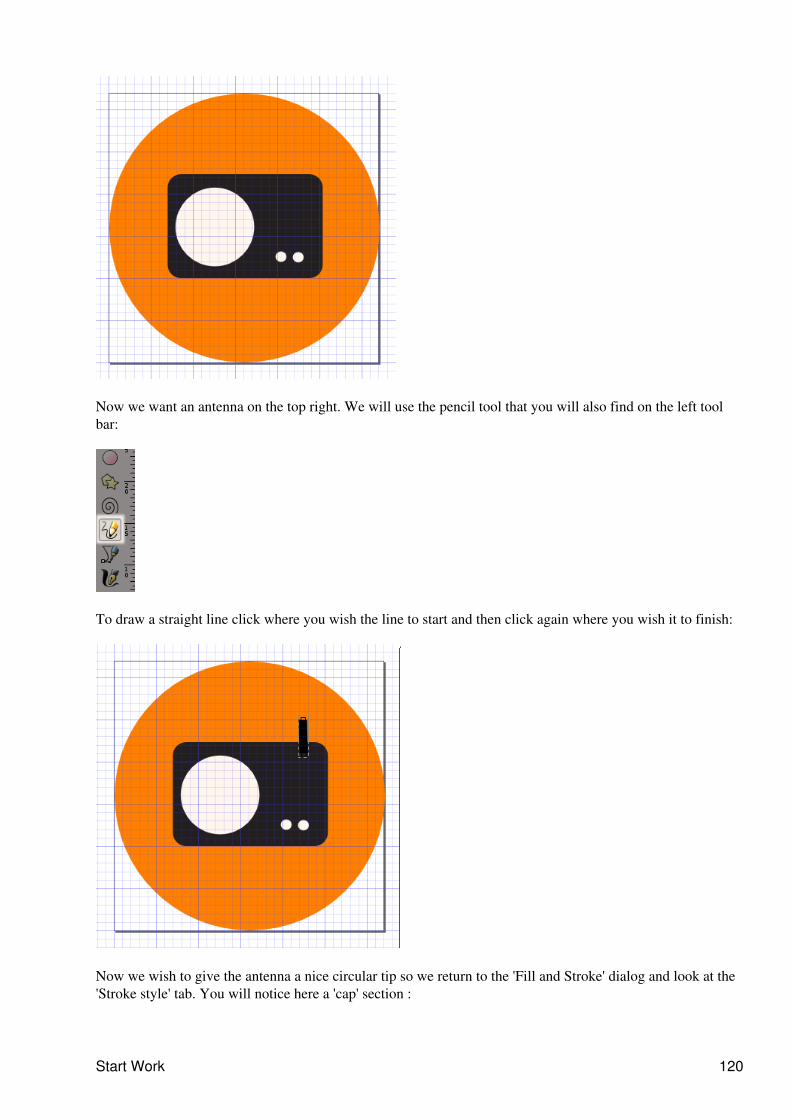
Now we want an antenna on the top right. We will use the pencil tool that you will also find on the left toolbar:
To draw a straight line click where you wish the line to start and then click again where you wish it to finish:
Now we wish to give the antenna a nice circular tip so we return to the 'Fill and Stroke' dialog and look at the'Stroke style' tab. You will notice here a 'cap' section :
Start Work 120
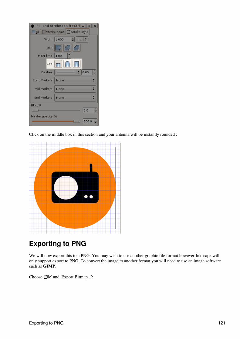
Click on the middle box in this section and your antenna will be instantly rounded :
Exporting to PNG
We will now export this to a PNG. You may wish to use another graphic file format however Inkscape willonly support export to PNG. To convert the image to another format you will need to use an image softwaresuch as GIMP.
Choose 'File' and 'Export Bitmap...':
Exporting to PNG 121
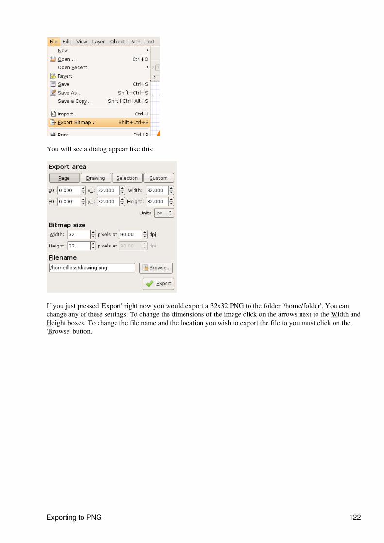
You will see a dialog appear like this:
If you just pressed 'Export' right now you would export a 32x32 PNG to the folder '/home/folder'. You canchange any of these settings. To change the dimensions of the image click on the arrows next to the Width andHeight boxes. To change the file name and the location you wish to export the file to you must click on the'Browse' button.
Exporting to PNG 122

LicenseAll chapters copyright of the authors (see below). Unless otherwise stated all chapters in this manual licensedwith GNU General Public License version 2
This documentation is free documentation; you can redistribute it and/or modify it under the terms of theGNU General Public License as published by the Free Software Foundation; either version 2 of the License,or (at your option) any later version.
This documentation is distributed in the hope that it will be useful, but WITHOUT ANY WARRANTY;without even the implied warranty of MERCHANTABILITY or FITNESS FOR A PARTICULARPURPOSE. See the GNU General Public License for more details.
You should have received a copy of the GNU General Public License along with this documentation; if not,write to the Free Software Foundation, Inc., 51 Franklin Street, Fifth Floor, Boston, MA 02110-1301, USA.
License 123
Authors3D BOX TOOL© Joshua Facemyer 2008Modifications:adam hyde 2008Alexandre Prokoudine 2008Cedric Gemy 2008
ABOUT SVG© ryan lerch 2008Modifications:adam hyde 2008Joshua Facemyer 2008
ALIGN AND DISTRIBUTE© Joshua Facemyer 2008Modifications:adam hyde 2008Cedric Gemy 2008Elisa de Castro Guerra 2008
BUCKET FILL TOOL© Joshua Facemyer 2008Modifications:adam hyde 2008Alexandre Prokoudine 2008Cedric Gemy 2008
CALLIGRAPHY TOOL© Joshua Facemyer 2008Modifications:adam hyde 2008Alexandre Prokoudine 2008Cedric Gemy 2008Olivier Gondouin-Liu 2008
CLIP AND MASK© ryan lerch 2008Modifications:adam hyde 2008Alexandre Prokoudine 2008Cedric Gemy 2008Elisa de Castro Guerra 2008
COLOR MANAGEMENT© Joshua Facemyer 2008Modifications:adam hyde 2008Alexandre Prokoudine 2008
COLOR SWATCHES© Joshua Facemyer 2008
Authors 124
Modifications:adam hyde 2008Bradley Cooper 2008
CONNECTOR TOOL© Michael Wybrow 2008Modifications:adam hyde 2008Alexandre Prokoudine 2008
COPY, CLONE, & DUPLICATE© Joshua Facemyer 2008Modifications:adam hyde 2008Cedric Gemy 2008Elisa de Castro Guerra 2008
CREATING ICONS© adam hyde 2008Modifications:Nicolas Dufour 2008Joshua Facemyer 2008
CREDITS© adam hyde 2006, 2007Modifications:Joshua Facemyer 2008Queen Victoria 2008TWikiGuest 2008
DROPPER TOOL© Joshua Facemyer 2008Modifications:adam hyde 2008Alexandre Prokoudine 2008
ELLIPSE TOOL© Joshua Facemyer 2008Modifications:adam hyde 2008Alexandre Prokoudine 2008Cedric Gemy 2008
GEARS© Joshua Facemyer 2008Modifications:adam hyde 2008Alexandre Prokoudine 2008Cedric Gemy 2008
GENERATE TEMPLATE© John Bintz 2008Modifications:
Authors 125

adam hyde 2008Alexandre Prokoudine 2008Nicolas Dufour 2008Joshua Facemyer 2008
GRADIENT TOOL© Joshua Facemyer 2008Modifications:adam hyde 2008Alexandre Prokoudine 2008Cedric Gemy 2008
GROUPING© Alexandre Prokoudine 2008Modifications:adam hyde 2008Cedric Gemy 2008Joshua Facemyer 2008
INSTALLING ON WINDOWS© adam hyde 2008Modifications:TWikiGuest 2008
THE INKSCAPE INTERFACE© Joshua Facemyer 2008Modifications:adam hyde 2008Cedric Gemy 2008Elisa de Castro Guerra 2008
ABOUT INKSCAPE© Joshua Facemyer 2008Modifications:adam hyde 2008Elisa de Castro Guerra 2008
INTRODUCTION© Cedric Gemy 2008Modifications:adam hyde 2008
INTRODUCTION© Alexandre Prokoudine 2008Modifications:adam hyde 2008Elisa de Castro Guerra 2008Joshua Facemyer 2008
LAYERS© Joshua Facemyer 2008Modifications:adam hyde 2008
Authors 126
INTRODUCTION© Joshua Facemyer 2008Modifications:adam hyde 2008Alexandre Prokoudine 2008Cedric Gemy 2008Elisa de Castro Guerra 2008
MODIFY PATH© Joshua Facemyer 2008Modifications:adam hyde 2008Alexandre Prokoudine 2008Cedric Gemy 2008
NODE TOOL© Joshua Facemyer 2008Modifications:adam hyde 2008Alexandre Prokoudine 2008Cedric Gemy 2008TWikiGuest 2008
PATTERN ALONG PATH© Joshua Facemyer 2008Modifications:adam hyde 2008Alexandre Prokoudine 2008Cedric Gemy 2008
PATTERN FILL© Alexandre Prokoudine 2008Modifications:adam hyde 2008Cedric Gemy 2008Elisa de Castro Guerra 2008Nicolas Dufour 2008Joshua Facemyer 2008
PEN TOOL© Joshua Facemyer 2008Modifications:adam hyde 2008Alexandre Prokoudine 2008Cedric Gemy 2008Elisa de Castro Guerra 2008
PENCIL TOOL© Joshua Facemyer 2008Modifications:adam hyde 2008Alexandre Prokoudine 2008
Authors 127
Cedric Gemy 2008Elisa de Castro Guerra 2008
RECTANGLE TOOL© Joshua Facemyer 2008Modifications:adam hyde 2008Alexandre Prokoudine 2008Cedric Gemy 2008
INTRODUCTION© Alexandre Prokoudine 2008Modifications:adam hyde 2008TWikiGuest 2008
SELECTOR TOOL© Joshua Facemyer 2008Modifications:adam hyde 2008Alexandre Prokoudine 2008Cedric Gemy 2008Elisa de Castro Guerra 2008
SPIRAL TOOL© Joshua Facemyer 2008Modifications:adam hyde 2008Cedric Gemy 2008Elisa de Castro Guerra 2008
STAR TOOL© Joshua Facemyer 2008Modifications:adam hyde 2008Olivier Gondouin-Liu 2008
STROKE STYLE© Alexandre Prokoudine 2008Modifications:adam hyde 2008Cedric Gemy 2008Elisa de Castro Guerra 2008Joshua Facemyer 2008
STYLING TEXT© Joshua Facemyer 2008Modifications:adam hyde 2008Alexandre Prokoudine 2008Cedric Gemy 2008
Authors 128

TEXT AND PATHS© Joshua Facemyer 2008Modifications:adam hyde 2008Alexandre Prokoudine 2008Cedric Gemy 2008
TEXT EFFECTS© Alexandre Prokoudine 2008Modifications:adam hyde 2008Cedric Gemy 2008Joshua Facemyer 2008
TEXT TOOL© Joshua Facemyer 2008Modifications:adam hyde 2008Cedric Gemy 2008
TWEAK TOOL© Joshua Facemyer 2008Modifications:adam hyde 2008Alexandre Prokoudine 2008Cedric Gemy 2008
WORKING WITH FILES© Joshua Facemyer 2008Modifications:adam hyde 2008Cedric Gemy 2008Elisa de Castro Guerra 2008Olivier Gondouin-Liu 2008TWikiGuest 2008
ZOOM TOOL© Joshua Facemyer 2008Modifications:adam hyde 2008Alexandre Prokoudine 2008Cedric Gemy 2008
Free manuals for free software
Authors 129
General Public LicenseVersion 2, June 1991
Copyright (C) 1989, 1991 Free Software Foundation, Inc.51 Franklin Street, Fifth Floor, Boston, MA 02110-1301, USA
Everyone is permitted to copy and distribute verbatim copiesof this license document, but changing it is not allowed.
Preamble
The licenses for most software are designed to take away your freedom to share and change it. By contrast,the GNU General Public License is intended to guarantee your freedom to share and change free software--tomake sure the software is free for all its users. This General Public License applies to most of the FreeSoftware Foundation's software and to any other program whose authors commit to using it. (Some other FreeSoftware Foundation software is covered by the GNU Lesser General Public License instead.) You can applyit to your programs, too.
When we speak of free software, we are referring to freedom, not price. Our General Public Licenses aredesigned to make sure that you have the freedom to distribute copies of free software (and charge for thisservice if you wish), that you receive source code or can get it if you want it, that you can change the softwareor use pieces of it in new free programs; and that you know you can do these things.
To protect your rights, we need to make restrictions that forbid anyone to deny you these rights or to ask youto surrender the rights. These restrictions translate to certain responsibilities for you if you distribute copies ofthe software, or if you modify it.
For example, if you distribute copies of such a program, whether gratis or for a fee, you must give therecipients all the rights that you have. You must make sure that they, too, receive or can get the source code.And you must show them these terms so they know their rights.
We protect your rights with two steps: (1) copyright the software, and (2) offer you this license which givesyou legal permission to copy, distribute and/or modify the software.
Also, for each author's protection and ours, we want to make certain that everyone understands that there is nowarranty for this free software. If the software is modified by someone else and passed on, we want itsrecipients to know that what they have is not the original, so that any problems introduced by others will notreflect on the original authors' reputations.
Finally, any free program is threatened constantly by software patents. We wish to avoid the danger thatredistributors of a free program will individually obtain patent licenses, in effect making the programproprietary. To prevent this, we have made it clear that any patent must be licensed for everyone's free use ornot licensed at all.
The precise terms and conditions for copying, distribution and modification follow.
TERMS AND CONDITIONS FOR COPYING, DISTRIBUTION AND MODIFICATION
0. This License applies to any program or other work which contains a notice placed by the copyright holdersaying it may be distributed under the terms of this General Public License. The "Program", below, refers toany such program or work, and a "work based on the Program" means either the Program or any derivativework under copyright law: that is to say, a work containing the Program or a portion of it, either verbatim orwith modifications and/or translated into another language. (Hereinafter, translation is included without
General Public License 130
limitation in the term "modification".) Each licensee is addressed as "you".
Activities other than copying, distribution and modification are not covered by this License; they are outsideits scope. The act of running the Program is not restricted, and the output from the Program is covered only ifits contents constitute a work based on the Program (independent of having been made by running theProgram). Whether that is true depends on what the Program does.
1. You may copy and distribute verbatim copies of the Program's source code as you receive it, in anymedium, provided that you conspicuously and appropriately publish on each copy an appropriate copyrightnotice and disclaimer of warranty; keep intact all the notices that refer to this License and to the absence ofany warranty; and give any other recipients of the Program a copy of this License along with the Program.
You may charge a fee for the physical act of transferring a copy, and you may at your option offer warrantyprotection in exchange for a fee.
2. You may modify your copy or copies of the Program or any portion of it, thus forming a work based on theProgram, and copy and distribute such modifications or work under the terms of Section 1 above, providedthat you also meet all of these conditions:
a) You must cause the modified files to carry prominent notices stating that you changed the files andthe date of any change.
b) You must cause any work that you distribute or publish, that in whole or in part contains or isderived from the Program or any part thereof, to be licensed as a whole at no charge to all third partiesunder the terms of this License.
c) If the modified program normally reads commands interactively when run, you must cause it, whenstarted running for such interactive use in the most ordinary way, to print or display an announcementincluding an appropriate copyright notice and a notice that there is no warranty (or else, saying thatyou provide a warranty) and that users may redistribute the program under these conditions, andtelling the user how to view a copy of this License. (Exception: if the Program itself is interactive butdoes not normally print such an announcement, your work based on the Program is not required toprint an announcement.)
These requirements apply to the modified work as a whole. If identifiable sections of that work are notderived from the Program, and can be reasonably considered independent and separate works in themselves,then this License, and its terms, do not apply to those sections when you distribute them as separate works.But when you distribute the same sections as part of a whole which is a work based on the Program, thedistribution of the whole must be on the terms of this License, whose permissions for other licensees extend tothe entire whole, and thus to each and every part regardless of who wrote it.
Thus, it is not the intent of this section to claim rights or contest your rights to work written entirely by you;rather, the intent is to exercise the right to control the distribution of derivative or collective works based onthe Program.
In addition, mere aggregation of another work not based on the Program with the Program (or with a workbased on the Program) on a volume of a storage or distribution medium does not bring the other work underthe scope of this License.
3. You may copy and distribute the Program (or a work based on it, under Section 2) in object code orexecutable form under the terms of Sections 1 and 2 above provided that you also do one of the following:
General Public License 131

a) Accompany it with the complete corresponding machine-readable source code, which must bedistributed under the terms of Sections 1 and 2 above on a medium customarily used for softwareinterchange; or,
b) Accompany it with a written offer, valid for at least three years, to give any third party, for acharge no more than your cost of physically performing source distribution, a completemachine-readable copy of the corresponding source code, to be distributed under the terms ofSections 1 and 2 above on a medium customarily used for software interchange; or,
c) Accompany it with the information you received as to the offer to distribute corresponding sourcecode. (This alternative is allowed only for noncommercial distribution and only if you received theprogram in object code or executable form with such an offer, in accord with Subsection b above.)
The source code for a work means the preferred form of the work for making modifications to it. For anexecutable work, complete source code means all the source code for all modules it contains, plus anyassociated interface definition files, plus the scripts used to control compilation and installation of theexecutable. However, as a special exception, the source code distributed need not include anything that isnormally distributed (in either source or binary form) with the major components (compiler, kernel, and so on)of the operating system on which the executable runs, unless that component itself accompanies theexecutable.
If distribution of executable or object code is made by offering access to copy from a designated place, thenoffering equivalent access to copy the source code from the same place counts as distribution of the sourcecode, even though third parties are not compelled to copy the source along with the object code.
4. You may not copy, modify, sublicense, or distribute the Program except as expressly provided under thisLicense. Any attempt otherwise to copy, modify, sublicense or distribute the Program is void, and willautomatically terminate your rights under this License. However, parties who have received copies, or rights,from you under this License will not have their licenses terminated so long as such parties remain in fullcompliance.
5. You are not required to accept this License, since you have not signed it. However, nothing else grants youpermission to modify or distribute the Program or its derivative works. These actions are prohibited by law ifyou do not accept this License. Therefore, by modifying or distributing the Program (or any work based on theProgram), you indicate your acceptance of this License to do so, and all its terms and conditions for copying,distributing or modifying the Program or works based on it.
6. Each time you redistribute the Program (or any work based on the Program), the recipient automaticallyreceives a license from the original licensor to copy, distribute or modify the Program subject to these termsand conditions. You may not impose any further restrictions on the recipients' exercise of the rights grantedherein. You are not responsible for enforcing compliance by third parties to this License.
7. If, as a consequence of a court judgment or allegation of patent infringement or for any other reason (notlimited to patent issues), conditions are imposed on you (whether by court order, agreement or otherwise) thatcontradict the conditions of this License, they do not excuse you from the conditions of this License. If youcannot distribute so as to satisfy simultaneously your obligations under this License and any other pertinentobligations, then as a consequence you may not distribute the Program at all. For example, if a patent licensewould not permit royalty-free redistribution of the Program by all those who receive copies directly orindirectly through you, then the only way you could satisfy both it and this License would be to refrainentirely from distribution of the Program.
If any portion of this section is held invalid or unenforceable under any particular circumstance, the balance ofthe section is intended to apply and the section as a whole is intended to apply in other circumstances.
General Public License 132
It is not the purpose of this section to induce you to infringe any patents or other property right claims or tocontest validity of any such claims; this section has the sole purpose of protecting the integrity of the freesoftware distribution system, which is implemented by public license practices. Many people have madegenerous contributions to the wide range of software distributed through that system in reliance on consistentapplication of that system; it is up to the author/donor to decide if he or she is willing to distribute softwarethrough any other system and a licensee cannot impose that choice.
This section is intended to make thoroughly clear what is believed to be a consequence of the rest of thisLicense.
8. If the distribution and/or use of the Program is restricted in certain countries either by patents or bycopyrighted interfaces, the original copyright holder who places the Program under this License may add anexplicit geographical distribution limitation excluding those countries, so that distribution is permitted only inor among countries not thus excluded. In such case, this License incorporates the limitation as if written in thebody of this License.
9. The Free Software Foundation may publish revised and/or new versions of the General Public License fromtime to time. Such new versions will be similar in spirit to the present version, but may differ in detail toaddress new problems or concerns.
Each version is given a distinguishing version number. If the Program specifies a version number of thisLicense which applies to it and "any later version", you have the option of following the terms and conditionseither of that version or of any later version published by the Free Software Foundation. If the Program doesnot specify a version number of this License, you may choose any version ever published by the FreeSoftware Foundation.
10. If you wish to incorporate parts of the Program into other free programs whose distribution conditions aredifferent, write to the author to ask for permission. For software which is copyrighted by the Free SoftwareFoundation, write to the Free Software Foundation; we sometimes make exceptions for this. Our decision willbe guided by the two goals of preserving the free status of all derivatives of our free software and ofpromoting the sharing and reuse of software generally.
NO WARRANTY
11. BECAUSE THE PROGRAM IS LICENSED FREE OF CHARGE, THERE IS NO WARRANTY FORTHE PROGRAM, TO THE EXTENT PERMITTED BY APPLICABLE LAW. EXCEPT WHENOTHERWISE STATED IN WRITING THE COPYRIGHT HOLDERS AND/OR OTHER PARTIESPROVIDE THE PROGRAM "AS IS" WITHOUT WARRANTY OF ANY KIND, EITHER EXPRESSEDOR IMPLIED, INCLUDING, BUT NOT LIMITED TO, THE IMPLIED WARRANTIES OFMERCHANTABILITY AND FITNESS FOR A PARTICULAR PURPOSE. THE ENTIRE RISK AS TOTHE QUALITY AND PERFORMANCE OF THE PROGRAM IS WITH YOU. SHOULD THE PROGRAMPROVE DEFECTIVE, YOU ASSUME THE COST OF ALL NECESSARY SERVICING, REPAIR ORCORRECTION.
12. IN NO EVENT UNLESS REQUIRED BY APPLICABLE LAW OR AGREED TO IN WRITING WILLANY COPYRIGHT HOLDER, OR ANY OTHER PARTY WHO MAY MODIFY AND/ORREDISTRIBUTE THE PROGRAM AS PERMITTED ABOVE, BE LIABLE TO YOU FOR DAMAGES,INCLUDING ANY GENERAL, SPECIAL, INCIDENTAL OR CONSEQUENTIAL DAMAGES ARISINGOUT OF THE USE OR INABILITY TO USE THE PROGRAM (INCLUDING BUT NOT LIMITED TOLOSS OF DATA OR DATA BEING RENDERED INACCURATE OR LOSSES SUSTAINED BY YOU ORTHIRD PARTIES OR A FAILURE OF THE PROGRAM TO OPERATE WITH ANY OTHERPROGRAMS), EVEN IF SUCH HOLDER OR OTHER PARTY HAS BEEN ADVISED OF THEPOSSIBILITY OF SUCH DAMAGES.
General Public License 133

END OF TERMS AND CONDITIONS
General Public License 134