SMARTPHONE RECEIVER RECEPTOR DE SMARTPHONE · 2 En WARNING • When speaker output is used by 4...
12
English Español SMARTPHONE RECEIVER RECEPTOR DE SMARTPHONE SPH-C10BT Installation Manual Manual de instalacion
Transcript of SMARTPHONE RECEIVER RECEPTOR DE SMARTPHONE · 2 En WARNING • When speaker output is used by 4...

EnglishEspañol
SMARTPHONE RECEIVERRECEPTOR DE SMARTPHONE
SPH-C10BT
Installation ManualManual de instalacion
2 En
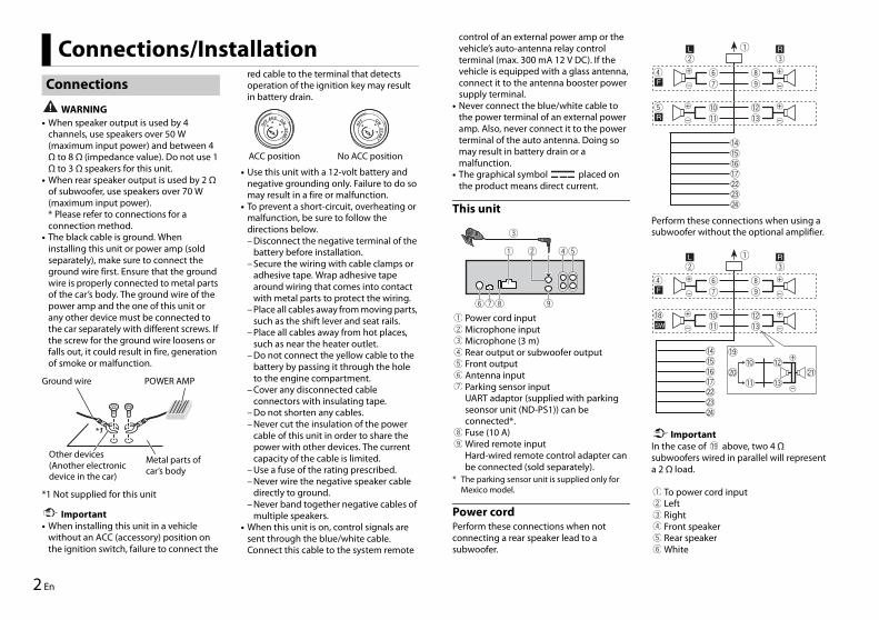
WARNING• When speaker output is used by 4
channels, use speakers over 50 W (maximum input power) and between 4 Ω to 8 Ω (impedance value). Do not use 1 Ω to 3 Ω speakers for this unit.
• When rear speaker output is used by 2 Ω of subwoofer, use speakers over 70 W (maximum input power).* Please refer to connections for a connection method.
• The black cable is ground. When installing this unit or power amp (sold separately), make sure to connect the ground wire first. Ensure that the ground wire is properly connected to metal parts of the car’s body. The ground wire of the power amp and the one of this unit or any other device must be connected to the car separately with different screws. If the screw for the ground wire loosens or falls out, it could result in fire, generation of smoke or malfunction.
Important• When installing this unit in a vehicle
without an ACC (accessory) position on the ignition switch, failure to connect the
red cable to the terminal that detects operation of the ignition key may result in battery drain.
• Use this unit with a 12-volt battery and negative grounding only. Failure to do so may result in a fire or malfunction.
• To prevent a short-circuit, overheating or malfunction, be sure to follow the directions below.– Disconnect the negative terminal of the
battery before installation.– Secure the wiring with cable clamps or
adhesive tape. Wrap adhesive tape around wiring that comes into contact with metal parts to protect the wiring.
– Place all cables away from moving parts, such as the shift lever and seat rails.
– Place all cables away from hot places, such as near the heater outlet.
– Do not connect the yellow cable to the battery by passing it through the hole to the engine compartment.
– Cover any disconnected cable connectors with insulating tape.
– Do not shorten any cables.– Never cut the insulation of the power
cable of this unit in order to share the power with other devices. The current capacity of the cable is limited.
– Use a fuse of the rating prescribed.– Never wire the negative speaker cable
directly to ground.– Never band together negative cables of
multiple speakers.• When this unit is on, control signals are
sent through the blue/white cable. Connect this cable to the system remote
Connections/InstallationConnections
Ground wire POWER AMP
Other devices (Another electronic device in the car)
Metal parts of car’s body
*1 Not supplied for this unit
ACC position No ACC position
control of an external power amp or the vehicle’s auto-antenna relay control terminal (max. 300 mA 12 V DC). If the vehicle is equipped with a glass antenna, connect it to the antenna booster power supply terminal.
• Never connect the blue/white cable to the power terminal of an external power amp. Also, never connect it to the power terminal of the auto antenna. Doing so may result in battery drain or a malfunction.
• The graphical symbol placed on the product means direct current.
This unit
Power cord inputMicrophone inputMicrophone (3 m)Rear output or subwoofer outputFront outputAntenna inputParking sensor inputUART adaptor (supplied with parking seonsor unit (ND-PS1)) can be connected*.Fuse (10 A)Wired remote inputHard-wired remote control adapter can be connected (sold separately).
* The parking sensor unit is supplied only for Mexico model.
Power cordPerform these connections when not connecting a rear speaker lead to a subwoofer.
Perform these connections when using a subwoofer without the optional amplifier.
ImportantIn the case of above, two 4 Ω subwoofers wired in parallel will represent a 2 Ω load.
To power cord inputLeftRightFront speakerRear speakerWhite

3En
English
White/blackGrayGray/blackGreenGreen/blackVioletViolet/blackBlack (chassis ground)Connect to a clean, paint-free metal location.YellowConnect to the constant 12 V supply terminal.RedConnect to terminal controlled by the ignition switch (12 V DC).Blue/whiteConnect to the system control terminal of the power amp or auto-antenna relay control terminal (max. 300 mA 12 V DC).Subwoofer (4 Ω)When using a subwoofer of 2 Ω, be sure to connect the subwoofer to the violet and violet/black leads of this unit. Do not connect anything to the green and green/black leads.Not used.Subwoofer (4 Ω) × 2Orange/whiteConnect to a car’s illumination signal.Violet/whiteOf the two lead wires connected to the back lamp, connect the one in which the voltage changes when the gear shift is in the REVERSE (R) position. This connection enables the unit to sense whether the car is moving forwards or backwards.Light greenUsed to detect the On/Off status of the parking brake. This lead must be connected to the power supply side of the parking brake switch.
NOTEChange the initial menu of this unit. Refer to [SP-P/O] in the INITIAL settings. The subwoofer output of this unit is monaural.
Power amp (sold separately)Perform these connections when using the optional amplifier.
System remote controlConnect to blue/white cable.Power amp (sold separately)Connect with RCA cables (sold separately)To front outputFront speakerTo rear output or subwoofer outputRear speaker or subwoofer
Important• Check all connections and systems before
final installation.• Do not use unauthorized parts as this
may cause malfunctions.• Consult your dealer if installation requires
drilling of holes or other modifications to the vehicle.
• Do not install this unit where:– it may interfere with operation of the
vehicle.– it may cause injury to a passenger as a
result of a sudden stop.• Install this unit away from hot places such
as near the heater outlet.
Installation
• Optimum performance is obtained when the unit is installed at an angle of less than 45°.
• When installing, to ensure proper heat dispersal when using this unit, make sure you leave ample space behind the rear panel and wrap any loose cables so they are not blocking the vents.
DIN mount installation1 Insert the supplied mounting sleeve
into the dashboard.2 Secure the mounting sleeve by using a
screwdriver to bend the metal tabs (90°) into place.
DashboardMounting sleeve
• Make sure that the unit is installed securely in place. An unstable installation may cause skipping or other malfunctions.
When not using the supplied mounting sleeve1 Determine the appropriate position
where the holes on the bracket and the side of the unit match.
2 Tighten two screws on each side.
Truss screw (5 mm × 9 mm)Mounting bracketDashboard or console
Removing the unit (installed with the supplied mounting sleeve)1 Remove the trim ring.
Trim ring• Releasing the front panel allows easier
access to the trim ring.• When reattaching the trim ring, point
the side with the dent part up.2 Insert the supplied extraction keys
into both sides of the unit until they click into place.
3 Pull the unit out of the dashboard.
Leave ample space
5 cm
5 cm
4 En
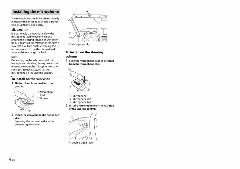
The microphone should be placed directly in front of the driver at a suitable distance to pick up their voice clearly.
CAUTIONIt is extremely dangerous to allow the microphone lead to become wound around the steering column or shift lever. Be sure to install the microphone in such a way that it will not obstruct driving. It is recommended to use the clamps (sold separately) to arrange the lead.
NOTEDepending on the vehicle model, the microphone cable length may be too short when you mount the microphone on the sun visor. In such cases, install the microphone on the steering column.
To install on the sun visor1 Fit the microphone lead into the
groove.
2 Install the microphone clip on the sun visor.Lowering the sun visor reduces the voice recognition rate.
To install on the steering column1 Slide the microphone base to detach it
from the microphone clip.
MicrophoneMicrophone clipMicrophone base
2 Install the microphone on the rear side of the steering column.
Installing the microphone
Microphone leadGroove
Microphone clip
Double-sided tape

5En
English
2 Es
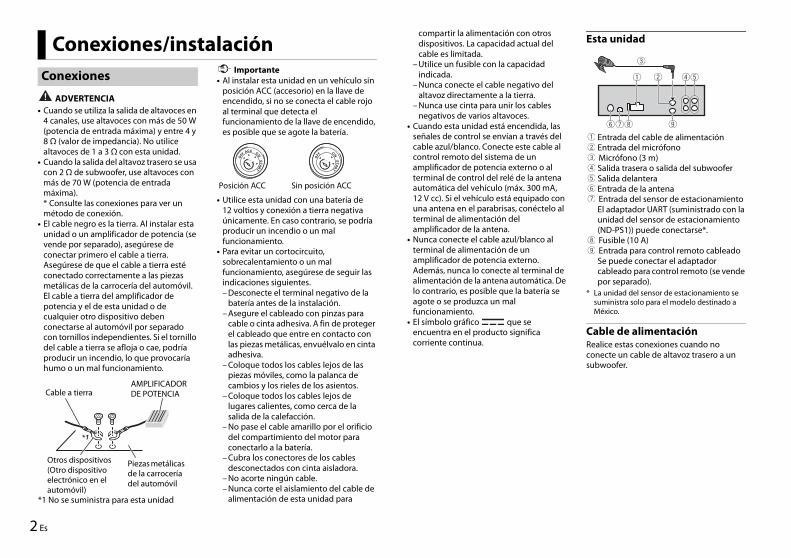
ADVERTENCIA• Cuando se utiliza la salida de altavoces en
4 canales, use altavoces con más de 50 W (potencia de entrada máxima) y entre 4 y 8 Ω (valor de impedancia). No utilice altavoces de 1 a 3 Ω con esta unidad.
• Cuando la salida del altavoz trasero se usa con 2 Ω de subwoofer, use altavoces con más de 70 W (potencia de entrada máxima).* Consulte las conexiones para ver un método de conexión.
• El cable negro es la tierra. Al instalar esta unidad o un amplificador de potencia (se vende por separado), asegúrese de conectar primero el cable a tierra. Asegúrese de que el cable a tierra esté conectado correctamente a las piezas metálicas de la carrocería del automóvil. El cable a tierra del amplificador de potencia y el de esta unidad o de cualquier otro dispositivo deben conectarse al automóvil por separado con tornillos independientes. Si el tornillo del cable a tierra se afloja o cae, podría producir un incendio, lo que provocaría humo o un mal funcionamiento.
Importante• Al instalar esta unidad en un vehículo sin
posición ACC (accesorio) en la llave de encendido, si no se conecta el cable rojo al terminal que detecta el funcionamiento de la llave de encendido, es posible que se agote la batería.
• Utilice esta unidad con una batería de 12 voltios y conexión a tierra negativa únicamente. En caso contrario, se podría producir un incendio o un mal funcionamiento.
• Para evitar un cortocircuito, sobrecalentamiento o un mal funcionamiento, asegúrese de seguir las indicaciones siguientes.– Desconecte el terminal negativo de la
batería antes de la instalación.– Asegure el cableado con pinzas para
cable o cinta adhesiva. A fin de proteger el cableado que entre en contacto con las piezas metálicas, envuélvalo en cinta adhesiva.
– Coloque todos los cables lejos de las piezas móviles, como la palanca de cambios y los rieles de los asientos.
– Coloque todos los cables lejos de lugares calientes, como cerca de la salida de la calefacción.
– No pase el cable amarillo por el orificio del compartimiento del motor para conectarlo a la batería.
– Cubra los conectores de los cables desconectados con cinta aisladora.
– No acorte ningún cable.– Nunca corte el aislamiento del cable de
alimentación de esta unidad para
Conexiones/instalaciónConexiones
Cable a tierraAMPLIFICADOR DE POTENCIA
Otros dispositivos (Otro dispositivo electrónico en el automóvil)
Piezas metálicas de la carrocería del automóvil
*1 No se suministra para esta unidad
Posición ACC Sin posición ACC
compartir la alimentación con otros dispositivos. La capacidad actual del cable es limitada.
– Utilice un fusible con la capacidad indicada.
– Nunca conecte el cable negativo del altavoz directamente a la tierra.
– Nunca use cinta para unir los cables negativos de varios altavoces.
• Cuando esta unidad está encendida, las señales de control se envían a través del cable azul/blanco. Conecte este cable al control remoto del sistema de un amplificador de potencia externo o al terminal de control del relé de la antena automática del vehículo (máx. 300 mA, 12 V cc). Si el vehículo está equipado con una antena en el parabrisas, conéctelo al terminal de alimentación del amplificador de la antena.
• Nunca conecte el cable azul/blanco al terminal de alimentación de un amplificador de potencia externo. Además, nunca lo conecte al terminal de alimentación de la antena automática. De lo contrario, es posible que la batería se agote o se produzca un mal funcionamiento.
• El símbolo gráfico que se encuentra en el producto significa corriente continua.
Esta unidad
Entrada del cable de alimentaciónEntrada del micrófono Micrófono (3 m)Salida trasera o salida del subwooferSalida delanteraEntrada de la antena Entrada del sensor de estacionamientoEl adaptador UART (suministrado con la unidad del sensor de estacionamiento (ND-PS1)) puede conectarse*. Fusible (10 A) Entrada para control remoto cableadoSe puede conectar el adaptador cableado para control remoto (se vende por separado).
* La unidad del sensor de estacionamiento se suministra solo para el modelo destinado a México.
Cable de alimentaciónRealice estas conexiones cuando no conecte un cable de altavoz trasero a un subwoofer.
3Es
Español
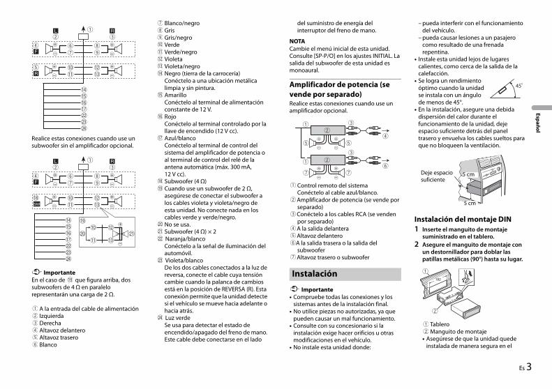
Realice estas conexiones cuando use un subwoofer sin el amplificador opcional.
ImportanteEn el caso de que figura arriba, dos subwoofers de 4 Ω en paralelo representarán una carga de 2 Ω.
A la entrada del cable de alimentaciónIzquierdaDerechaAltavoz delanteroAltavoz traseroBlanco
Blanco/negroGrisGris/negroVerdeVerde/negroVioletaVioleta/negroNegro (tierra de la carrocería)Conéctelo a una ubicación metálica limpia y sin pintura.AmarilloConéctelo al terminal de alimentación constante de 12 V.RojoConéctelo al terminal controlado por la llave de encendido (12 V cc).Azul/blancoConéctelo al terminal de control del sistema del amplificador de potencia o al terminal de control del relé de la antena automática (máx. 300 mA, 12 V cc).Subwoofer (4 Ω)Cuando use un subwoofer de 2 Ω, asegúrese de conectar el subwoofer a los cables violeta y violeta/negro de esta unidad. No conecte nada en los cables verde y verde/negro.No se usa.Subwoofer (4 Ω) × 2 Naranja/blancoConéctelo a la señal de iluminación del automóvil. Violeta/blancoDe los dos cables conectados a la luz de reversa, conecte el cable cuya tensión cambie cuando la palanca de cambios está en la posición de REVERSA (R). Esta conexión permite que la unidad detecte si el vehículo se mueve hacia adelante o hacia atrás. Luz verdeSe usa para detectar el estado de encendido/apagado del freno de mano. Este cable debe conectarse en el lado
del suministro de energía del interruptor del freno de mano.
NOTACambie el menú inicial de esta unidad. Consulte [SP-P/O] en los ajustes INITIAL. La salida del subwoofer de esta unidad es monoaural.
Amplificador de potencia (se vende por separado)Realice estas conexiones cuando use un amplificador opcional.
Control remoto del sistemaConéctelo al cable azul/blanco.Amplificador de potencia (se vende por separado)Conéctelo a los cables RCA (se venden por separado)A la salida delanteraAltavoz delanteroA la salida trasera o la salida del subwooferAltavoz trasero o subwoofer
Importante• Compruebe todas las conexiones y los
sistemas antes de la instalación final.• No utilice piezas no autorizadas, ya que
pueden causar un mal funcionamiento.• Consulte con su concesionario si la
instalación exige hacer orificios u otras modificaciones en el vehículo.
• No instale esta unidad donde:
– pueda interferir con el funcionamiento del vehículo.
– pueda causar lesiones a un pasajero como resultado de una frenada repentina.
• Instale esta unidad lejos de lugares calientes, como cerca de la salida de la calefacción.
• Se logra un rendimiento óptimo cuando la unidad se instala con un ángulo de menos de 45°.
• En la instalación, asegure una debida dispersión del calor durante el funcionamiento de la unidad, deje espacio suficiente detrás del panel trasero y envuelva los cables sueltos para que no bloqueen la ventilación.
Instalación del montaje DIN1 Inserte el manguito de montaje
suministrado en el tablero.2 Asegure el manguito de montaje con
un destornillador para doblar las patillas metálicas (90°) hasta su lugar.
TableroManguito de montaje
• Asegúrese de que la unidad quede instalada de manera segura en el
Instalación
Deje espacio suficiente
5 cm
5 cm
4 Es
lugar. Una instalación inestable puede provocar saltos u otras fallas de funcionamiento.
En caso de que no se utilice el manguito de montaje suministrado1 Establezca la posición adecuada
donde coincidan los orificios del soporte y del costado de la unidad.
2 Apriete dos tornillos a cada lado.
Tornillo de cabeza redonda (5 mm × 9 mm)Soporte de montajeTablero o consola
Extracción de la unidad (instalada con el manguito de montaje que se entrega)1 Quite el anillo de ajuste.
Anillo de ajuste• Quitar el panel frontal permite un
acceso más sencillo al anillo de ajuste.• Cuando vuelva a colocar el anillo de
ajuste, oriente el lado con la parte dentada hacia arriba.
2 Inserte las llaves de extracción suministradas a ambos lados de la unidad hasta que calcen en el lugar.
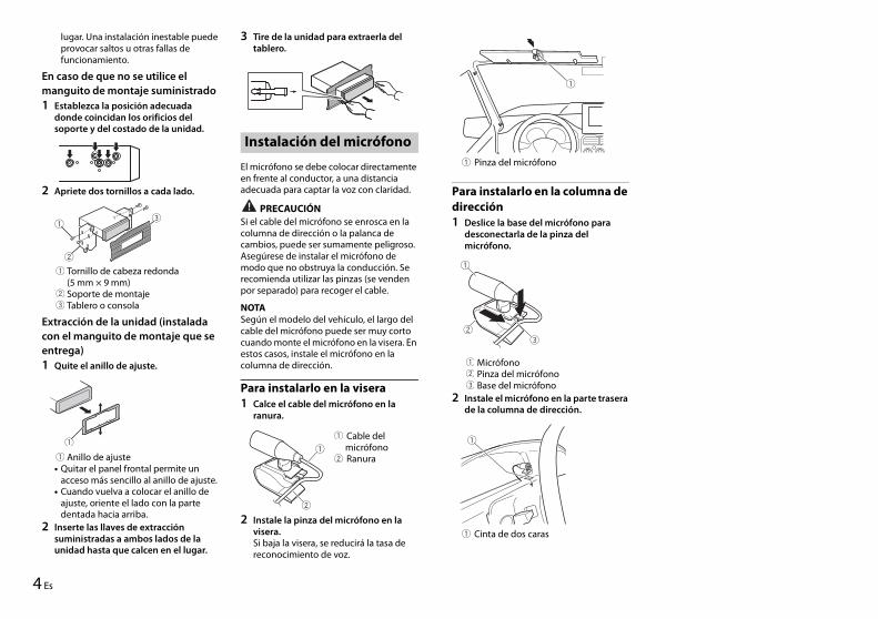
3 Tire de la unidad para extraerla del tablero.
El micrófono se debe colocar directamente en frente al conductor, a una distancia adecuada para captar la voz con claridad.
PRECAUCIÓNSi el cable del micrófono se enrosca en la columna de dirección o la palanca de cambios, puede ser sumamente peligroso. Asegúrese de instalar el micrófono de modo que no obstruya la conducción. Se recomienda utilizar las pinzas (se venden por separado) para recoger el cable.
NOTASegún el modelo del vehículo, el largo del cable del micrófono puede ser muy corto cuando monte el micrófono en la visera. En estos casos, instale el micrófono en la columna de dirección.
Para instalarlo en la visera1 Calce el cable del micrófono en la
ranura.
2 Instale la pinza del micrófono en la visera.Si baja la visera, se reducirá la tasa de reconocimiento de voz.
Instalación del micrófono
Cable del micrófono Ranura
Para instalarlo en la columna de dirección1 Deslice la base del micrófono para
desconectarla de la pinza del micrófono.
MicrófonoPinza del micrófonoBase del micrófono
2 Instale el micrófono en la parte trasera de la columna de dirección.
Pinza del micrófono
Cinta de dos caras

5Es
Español

6 Es

7Es
Español
© 2018 PIONEER CORPORATION. All rights reserved.
<CRD5091-A> ES/ME