Efficient Realization of Sigma-Delta Kalman Lowpass Filter in Hardware Using FPGA
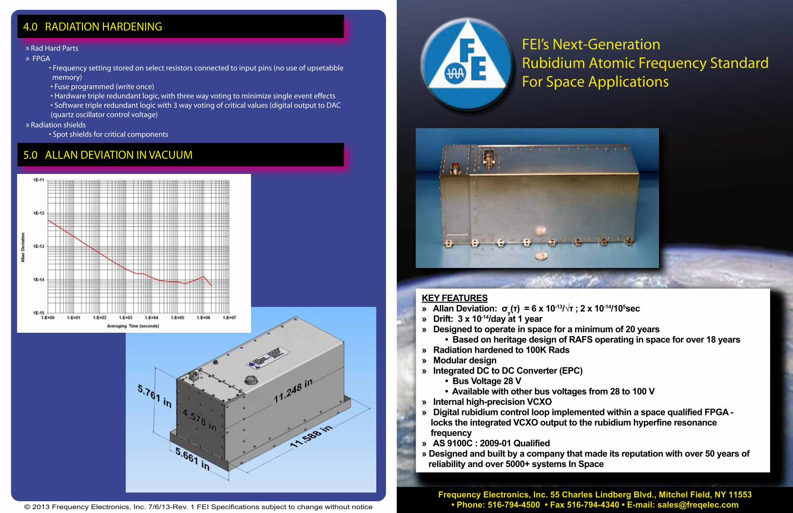
KEY FEATURES» Allan Deviation: σy(τ) = 6 x 10-13/√τ ; 2 x 10-14/105sec» Drift: 3 x 10-14/day at 1 year» Designed to operate in space for a minimum of 20 years • Based on heritage design of RAFS operating in space for over 18 years» Radiation hardened to 100K Rads» Modular design» Integrated DC to DC Converter (EPC) • Bus Voltage 28 V • Available with other bus voltages from 28 to 100 V» Internal high-precision VCXO» Digital rubidium control loop implemented within a space qualified FPGA - locks the integrated VCXO output to the rubidium hyperfine resonance frequency» AS 9100C : 2009-01 Qualified» Designed and built by a company that made its reputation with over 50 years of reliability and over 5000+ systems In Space
FEI’s Next-Generation Rubidium Atomic Frequency Standard For Space Applications
© 2013 Frequency Electronics, Inc. 7/6/13-Rev. 1 FEI Specifications subject to change without notice
» Rad Hard Parts» FPGA • Frequency setting stored on select resistors connected to input pins (no use of upsetabble memory) • Fuse programmed (write once) • Hardware triple redundant logic, with three way voting to minimize single event effects • Software triple redundant logic with 3 way voting of critical values (digital output to DAC (quartz oscillator control voltage)» Radiation shields • Spot shields for critical components
5.0 ALLAN DEVIATION IN VACUUM
4.0 RADIATION HARDENING
Frequency Electronics, Inc. 55 Charles Lindberg Blvd., Mitchel Field, NY 11553• Phone: 516-794-4500 • Fax 516-794-4340 • E-mail: [email protected]
Frequency Electronics, Inc. (FEI) has developed a rubidium atomic frequency standard (RAFS) for precision time-keeping and stable frequency generation for global navigation satellite systems (GNSS). FEI has leveraged its experience from rubidium standards provided to the Milstar constellation and to the Advanced Extremely High Frequency (AEHF) satellite program. A total quantity of 19 rubidium standards were delivered for Milstar and launched starting in 1995. For AEHF 12 rubidium standards have been provided with an additional 9 on order. The first AEHF satellite was launched in August 2010, the second was launched in May 2012 and the third is scheduled for launch in fourth quarter of 2013.
RF Output 10.0 MHz or 10.23 MHz Sinewave (other frequencies can be provided)+ 18 dBm ± 1.5 dBHarmonics ≤ -50 dBcSpurious ≤ -85 dBc
Analog Monitors Lock, Light , Signal, VCXO, Baseplate Temperature, Ovens, Power Supplies , ALC, C-Field, BTC
Accuracy ± 1 x 10⁻⁹ at shipmentTrim Range None (Fixed C-Field)Stability σy(τ) 6 x 10-13 τ-½ 2 x 10-14
≤ 1 x 10-13/day at BOL operation≤ 3 x 10-14
Phase Noise, f(f)-138 dBc/Hz at 10 Hz -148 dBc/Hz at 100 Hz -158 dBc/Hz at 1 KHz
Temperature Sensitivity ≤ 2 x 10-13/°C typical w/o BTC, below noise level for ± 1.5°C with BTCVoltage Sensitivity ≤ 3 x 10-12 Magnetic Sensitivity ≤ 1 x 10-12/GaussBarometric Sensitivity ≤ 1 x 10-13/mbar typical Retrace ≤ 5 x 10-12
Input Power 28.0 VDC ± 4.0 VDC (Available with other bus voltages from 28 to 100 V)≤ 39 W total steady-state with BTC ( -4 to + 21C)≤ 20 W basic clock at +45° C baseplate≤ 65 W during warm-up
Warm-up ≤ 1 hour to ± 2 x 10⁻¹⁰
Size ( L x W x H) 11.2 x 4.6 x 5.8 in 285 x 117 x 147 mm
Mass 16.5 lbs/7.5 kg
Operating Temperature Full performance with BTC range between -4°C and +25°C panel tem-perature.Functional between -20°C to +45°C panel temperature.
Storage Temperature -34°C to + 71°CAltitude Sea level to vacuumVibration 12.4g rms, 20 Hz to 2 kHzPyroshock 1500 g max to 10 kHzAcceleration 20 gRadiation 100 K RadEMI Per MIL–STD-461E
1 in 1,000 Years≥1000 cycles
1.0 INTRODUCTION
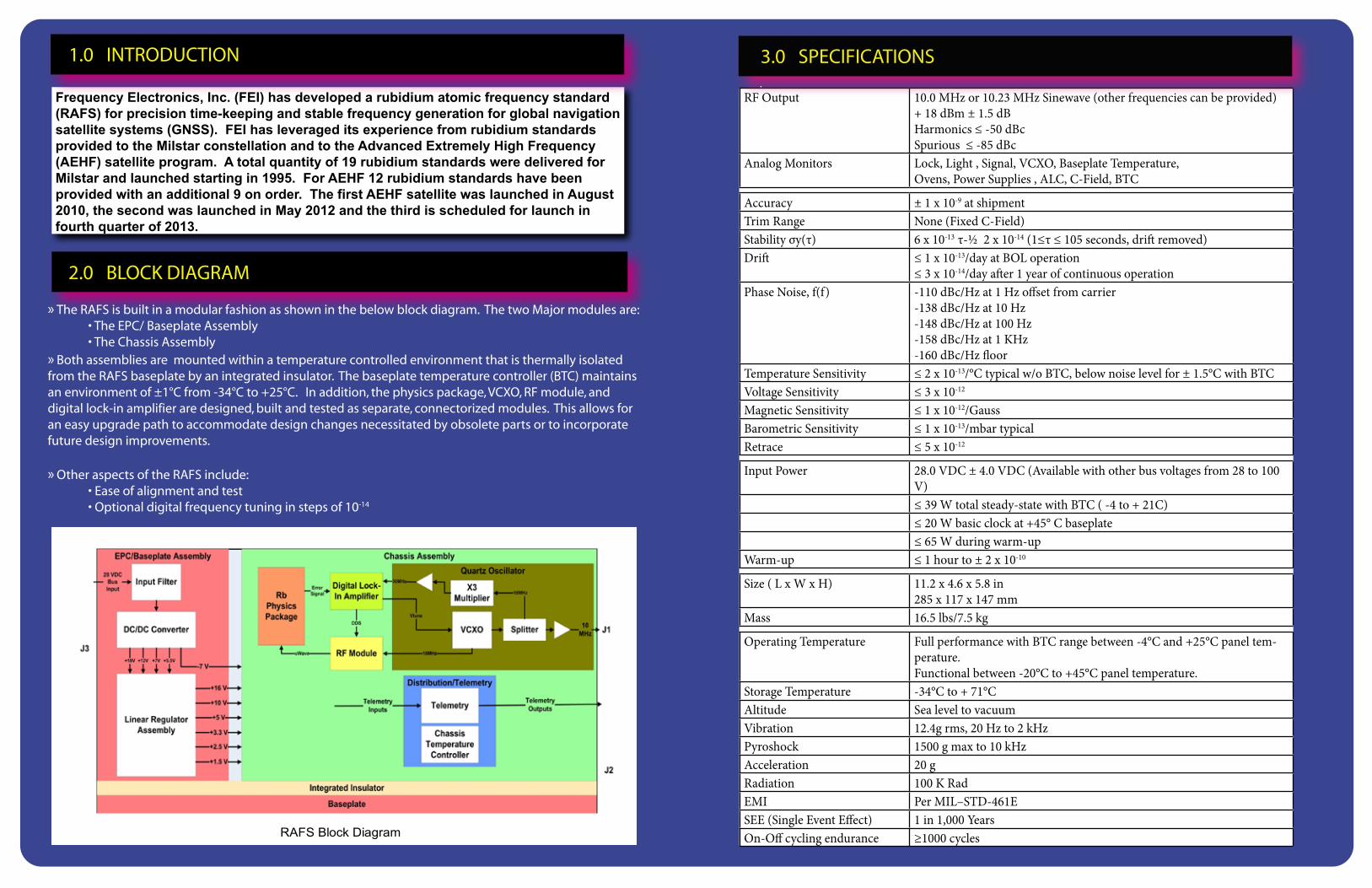
» The RAFS is built in a modular fashion as shown in the below block diagram. The two Major modules are: • The EPC/ Baseplate Assembly • The Chassis Assembly» Both assemblies are mounted within a temperature controlled environment that is thermally isolated from the RAFS baseplate by an integrated insulator. The baseplate temperature controller (BTC) maintains an environment of ±1°C from -34°C to +25°C. In addition, the physics package, VCXO, RF module, and digital lock-in amplifier are designed, built and tested as separate, connectorized modules. This allows for an easy upgrade path to accommodate design changes necessitated by obsolete parts or to incorporate future design improvements.
» Other aspects of the RAFS include: • Ease of alignment and test • Optional digital frequency tuning in steps of 10-14
2.0 BLOCK DIAGRAM
RAFS Block Diagram
3.0 SPECIFICATIONS