Specifications Ordering Information - Farnell element14 Text 116 Text Specifications Coil...
16
116 Text PCB Power Relay – G2R Rated coil voltage Note: 1. When ordering, add the rated coil voltage to the model number. Example: G2R-1A 12 VDC 2. Models with CTI250 material are also available. Contact your OMRON representative for more details. Ordering Information Classification Enclosure Ratings Coil Ratings Contact Form SPST-NO SPDT DPST-NO DPDT PCB terminal General-purpose Flux protection AC/DC G2R-1A G2R-1 G2R-2A G2R-2 Fully sealed G2R-1A4 G2R-14 G2R-2A4 G2R-24 Bifurcated contact Flux protection DC G2R-1AZ G2R-1Z – – Fully sealed G2R-1AZ4 G2R-1Z4 – – High-capacity Flux protection AC/DC G2R-1A-E G2R-1-E – – High-sensitivity Flux protection DC G2R-1A-H G2R-1-H G2R-2A-H G2R-2-H Double-winding latching Flux protection G2RK-1A G2RK-1 G2RK-2A G2RK-2 General-purpose Unsealed AC G2R-1A-T G2R1-T – – DC – – Quick connect (upper bracket mounting) A Power Relay for a Variety of Purposes with Various Models ■ ROHS compliant ■ Conforms to EN 61810-1, UL508, CSA22.2, SEV, SEMKO. ■ Meets EN60335-1 requirements for household products. ■ Clearance and creepage distance: 8 mm/8 m. ■ Models with CTI250 material available. ■ High-sensitivity (360 mW) and high-capacity (16 A) types available. ■ Double-winding latching type available.
-
Upload
trinhthuan -
Category
Documents
-
view
232 -
download
1
Transcript of Specifications Ordering Information - Farnell element14 Text 116 Text Specifications Coil...
117
Text
116
Text
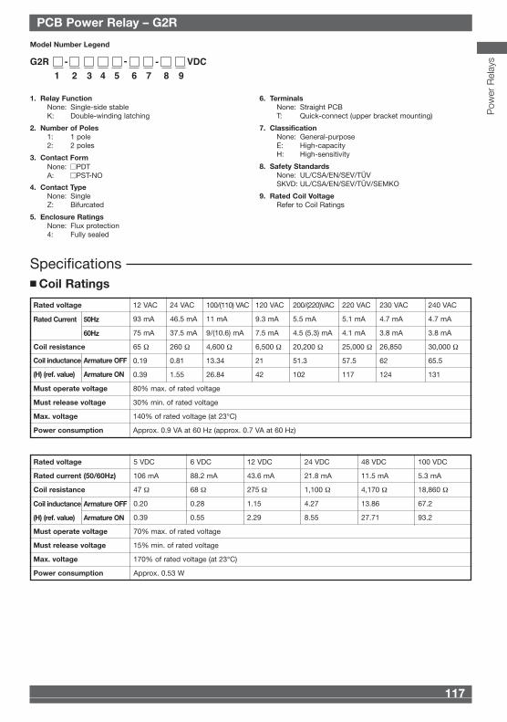
Specifications■ Coil Ratings
Rated voltage 5 VDC 6 VDC 12 VDC 24 VDC 48 VDC 100 VDC
Rated current (50/60Hz) 106 mA 88.2 mA 43.6 mA 21.8 mA 11.5 mA 5.3 mA
Coil resistance 47 Ω 68 Ω 275 Ω 1,100 Ω 4,170 Ω 18,860 Ω
0.20 0.28 1.15 4.27 13.86 67.2
0.39 0.55 2.29 8.55 27.71 93.2
Must operate voltage 70% max. of rated voltage
Must release voltage 15% min. of rated voltage
Max. voltage 170% of rated voltage (at 23°C)
Power consumption Approx. 0.53 W
Coil inductance Armature OFF
(H) (ref. value) Armature ON
Rated voltage 12 VAC 24 VAC 100/(110) VAC 120 VAC 200/(220)VAC 220 VAC 230 VAC 240 VAC
93 mA 46.5 mA 11 mA 9.3 mA 5.5 mA 5.1 mA 4.7 mA 4.7 mA
75 mA 37.5 mA 9/(10.6) mA 7.5 mA 4.5 (5.3) mA 4.1 mA 3.8 mA 3.8 mA
Coil resistance 65 Ω 260 Ω 4,600 Ω 6,500 Ω 20,200 Ω 25,000 Ω 26,850 30,000 Ω
0.19 0.81 13.34 21 51.3 57.5 62 65.5
0.39 1.55 26.84 42 102 117 124 131
Must operate voltage 80% max. of rated voltage
Must release voltage 30% min. of rated voltage
Max. voltage 140% of rated voltage (at 23°C)
Power consumption Approx. 0.9 VA at 60 Hz (approx. 0.7 VA at 60 Hz)
Coil inductance Armature OFF
(H) (ref. value) Armature ON
Rated Current 50Hz
60Hz
Model Number Legend
G2R - VDC
1 2 3 4 5 6 7 8 9
--
1. Relay FunctionNone: Single-side stableK: Double-winding latching
2. Number of Poles1: 1 pole2: 2 poles
3. Contact FormNone: ■PDTA: ■PST-NO
4. Contact TypeNone: SingleZ: Bifurcated
5. Enclosure RatingsNone: Flux protection4: Fully sealed
6. TerminalsNone: Straight PCB T: Quick-connect (upper bracket mounting)
7. ClassificationNone: General-purposeE: High-capacityH: High-sensitivity
8. Safety StandardsNone: UL/CSA/EN/SEV/TÜVSKVD: UL/CSA/EN/SEV/TÜV/SEMKO
9. Rated Coil VoltageRefer to Coil Ratings
PCB Power Relay – G2RPCB Power Relay – G2R
Pow
er R
elay
s
Rated coil voltage
Note: 1. When ordering, add the rated coil voltage to the model number.Example: G2R-1A 12 VDC
2. Models with CTI250 material are also available.Contact your OMRON representative for more details.
Ordering Information
Classification EnclosureRatings
CoilRatings
Contact Form
SPST-NO SPDT DPST-NO DPDT
PCB terminal General-purpose Flux protection AC/DC G2R-1A G2R-1 G2R-2A G2R-2
Fully sealed G2R-1A4 G2R-14 G2R-2A4 G2R-24
Bifurcated contact Flux protection DC G2R-1AZ G2R-1Z – –
Fully sealed G2R-1AZ4 G2R-1Z4 – –
High-capacity Flux protection AC/DC G2R-1A-E G2R-1-E – –
High-sensitivity Flux protection DC G2R-1A-H G2R-1-H G2R-2A-H G2R-2-H
Double-winding latching Flux protection G2RK-1A G2RK-1 G2RK-2A G2RK-2
General-purpose Unsealed AC G2R-1A-T G2R1-T – –
DC – –
Quick connect(upper bracketmounting)
A Power Relay for a Variety ofPurposes with Various Models■ ROHS compliant■ Conforms to EN 61810-1, UL508, CSA22.2,
SEV, SEMKO.■ Meets EN60335-1 requirements for household
products.■ Clearance and creepage distance:
8 mm/8 m.■ Models with CTI250 material available.■ High-sensitivity (360 mW) and high-capacity
(16 A) types available.■ Double-winding latching type available.
Omron 08 Cat 1-302 5/10/07 15:39 Page 116
117
Text
116
Text
Specifications■ Coil Ratings
Rated voltage 5 VDC 6 VDC 12 VDC 24 VDC 48 VDC 100 VDC
Rated current (50/60Hz) 106 mA 88.2 mA 43.6 mA 21.8 mA 11.5 mA 5.3 mA
Coil resistance 47 Ω 68 Ω 275 Ω 1,100 Ω 4,170 Ω 18,860 Ω
0.20 0.28 1.15 4.27 13.86 67.2
0.39 0.55 2.29 8.55 27.71 93.2
Must operate voltage 70% max. of rated voltage
Must release voltage 15% min. of rated voltage
Max. voltage 170% of rated voltage (at 23°C)
Power consumption Approx. 0.53 W
Coil inductance Armature OFF
(H) (ref. value) Armature ON
Rated voltage 12 VAC 24 VAC 100/(110) VAC 120 VAC 200/(220)VAC 220 VAC 230 VAC 240 VAC
93 mA 46.5 mA 11 mA 9.3 mA 5.5 mA 5.1 mA 4.7 mA 4.7 mA
75 mA 37.5 mA 9/(10.6) mA 7.5 mA 4.5 (5.3) mA 4.1 mA 3.8 mA 3.8 mA
Coil resistance 65 Ω 260 Ω 4,600 Ω 6,500 Ω 20,200 Ω 25,000 Ω 26,850 30,000 Ω
0.19 0.81 13.34 21 51.3 57.5 62 65.5
0.39 1.55 26.84 42 102 117 124 131
Must operate voltage 80% max. of rated voltage
Must release voltage 30% min. of rated voltage
Max. voltage 140% of rated voltage (at 23°C)
Power consumption Approx. 0.9 VA at 60 Hz (approx. 0.7 VA at 60 Hz)
Coil inductance Armature OFF
(H) (ref. value) Armature ON
Rated Current 50Hz
60Hz
Model Number Legend
G2R - VDC
1 2 3 4 5 6 7 8 9
--
1. Relay FunctionNone: Single-side stableK: Double-winding latching
2. Number of Poles1: 1 pole2: 2 poles
3. Contact FormNone: ■PDTA: ■PST-NO
4. Contact TypeNone: SingleZ: Bifurcated
5. Enclosure RatingsNone: Flux protection4: Fully sealed
6. TerminalsNone: Straight PCB T: Quick-connect (upper bracket mounting)
7. ClassificationNone: General-purposeE: High-capacityH: High-sensitivity
8. Safety StandardsNone: UL/CSA/EN/SEV/TÜVSKVD: UL/CSA/EN/SEV/TÜV/SEMKO
9. Rated Coil VoltageRefer to Coil Ratings
PCB Power Relay – G2RPCB Power Relay – G2R
Pow
er R
elay
s
Rated coil voltage
Note: 1. When ordering, add the rated coil voltage to the model number.Example: G2R-1A 12 VDC
2. Models with CTI250 material are also available.Contact your OMRON representative for more details.
Ordering Information
Classification EnclosureRatings
CoilRatings
Contact Form
SPST-NO SPDT DPST-NO DPDT
PCB terminal General-purpose Flux protection AC/DC G2R-1A G2R-1 G2R-2A G2R-2
Fully sealed G2R-1A4 G2R-14 G2R-2A4 G2R-24
Bifurcated contact Flux protection DC G2R-1AZ G2R-1Z – –
Fully sealed G2R-1AZ4 G2R-1Z4 – –
High-capacity Flux protection AC/DC G2R-1A-E G2R-1-E – –
High-sensitivity Flux protection DC G2R-1A-H G2R-1-H G2R-2A-H G2R-2-H
Double-winding latching Flux protection G2RK-1A G2RK-1 G2RK-2A G2RK-2
General-purpose Unsealed AC G2R-1A-T G2R1-T – –
DC – –
Quick connect(upper bracketmounting)
A Power Relay for a Variety ofPurposes with Various Models■ ROHS compliant■ Conforms to EN 61810-1, UL508, CSA22.2,
SEV, SEMKO.■ Meets EN60335-1 requirements for household
products.■ Clearance and creepage distance:
8 mm/8 m.■ Models with CTI250 material available.■ High-sensitivity (360 mW) and high-capacity
(16 A) types available.■ Double-winding latching type available.
Omron 08 Cat 1-302 5/10/07 15:39 Page 116
119
Text
118
Text
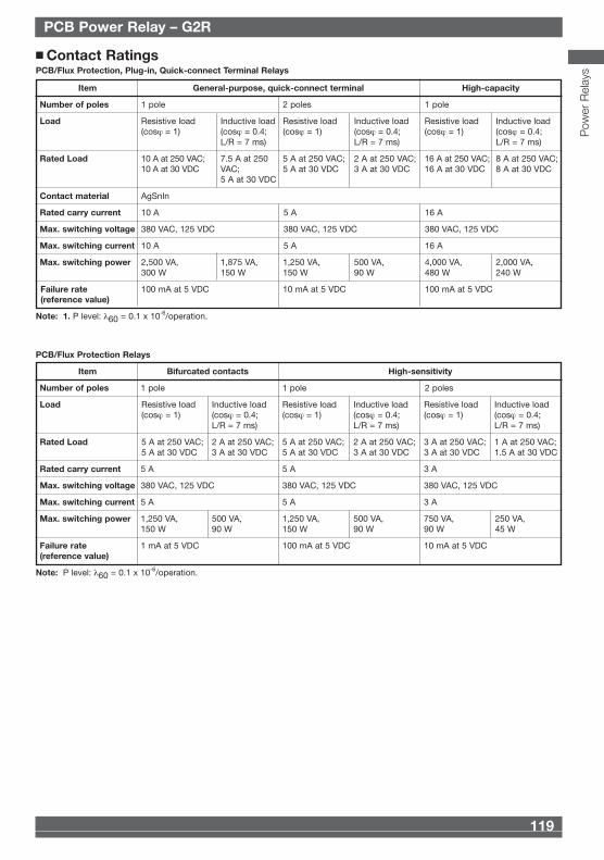
Item Bifurcated contacts High-sensitivity
Number of poles 1 pole 1 pole 2 poles
Load Resistive load Inductive load Resistive load Inductive load Resistive load Inductive load(cosϕ = 1) (cosϕ = 0.4; (cosϕ = 1) (cosϕ = 0.4; (cosϕ = 1) (cosϕ = 0.4;
L/R = 7 ms) L/R = 7 ms) L/R = 7 ms)
Rated Load 5 A at 250 VAC; 2 A at 250 VAC; 5 A at 250 VAC; 2 A at 250 VAC; 3 A at 250 VAC; 1 A at 250 VAC; 5 A at 30 VDC 3 A at 30 VDC 5 A at 30 VDC 3 A at 30 VDC 3 A at 30 VDC 1.5 A at 30 VDC
Rated carry current 5 A 5 A 3 A
Max. switching voltage 380 VAC, 125 VDC 380 VAC, 125 VDC 380 VAC, 125 VDC
Max. switching current 5 A 5 A 3 A
Max. switching power 1,250 VA, 500 VA, 1,250 VA, 500 VA, 750 VA, 250 VA,150 W 90 W 150 W 90 W 90 W 45 W
Failure rate 1 mA at 5 VDC 100 mA at 5 VDC 10 mA at 5 VDC(reference value)
Note: P level: λ60 = 0.1 x 10⁻⁶/operation.
PCB/Flux Protection Relays
Item General-purpose, quick-connect terminal High-capacity
Number of poles 1 pole 2 poles 1 pole
Load Resistive load Inductive load Resistive load Inductive load Resistive load Inductive load(cosϕ = 1) (cosϕ = 0.4; (cosϕ = 1) (cosϕ = 0.4; (cosϕ = 1) (cosϕ = 0.4;
L/R = 7 ms) L/R = 7 ms) L/R = 7 ms)
Rated Load 10 A at 250 VAC; 7.5 A at 250 5 A at 250 VAC; 2 A at 250 VAC; 16 A at 250 VAC; 8 A at 250 VAC;10 A at 30 VDC VAC; 5 A at 30 VDC 3 A at 30 VDC 16 A at 30 VDC 8 A at 30 VDC
5 A at 30 VDC
Contact material AgSnIn
Rated carry current 10 A 5 A 16 A
Max. switching voltage 380 VAC, 125 VDC 380 VAC, 125 VDC 380 VAC, 125 VDC
Max. switching current 10 A 5 A 16 A
Max. switching power 2,500 VA, 1,875 VA, 1,250 VA, 500 VA, 4,000 VA, 2,000 VA,300 W 150 W 150 W 90 W 480 W 240 W
Failure rate 100 mA at 5 VDC 10 mA at 5 VDC 100 mA at 5 VDC(reference value)
Note: 1. P level: λ60 = 0.1 x 10⁻⁶/operation.
■ Contact RatingsPCB/Flux Protection, Plug-in, Quick-connect Terminal Relays
PCB Power Relay – G2RPCB Power Relay – G2R
Pow
er R
elay
s
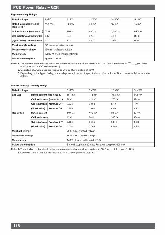
High-sensitivity Relays
Rated voltage 5 VDC 6 VDC 12 VDC 24 VDC 48 VDC
Rated current (50/60Hz) 71.4 mA 60 mA 30 mA 15 mA 7.5 mA(see Note. 1)
Coil resistance (see Note. 1) 70 Ω 100 Ω 400 Ω 1,600 Ω 6,400 Ω
0.37 0.53 2.14 7.80 31.20
0.75 1.07 4.27 15.60 62.40
Must operate voltage 70% max. of rated voltage
Must release voltage 15% min. of rated voltage
Max. voltage 170% of rated voltage (at 23°C)
Power consumption Approx. 0.36 W
Note: 1. The rated current and coil resistance are measured at a coil temperature of 23°C with a tolerance of +15%/–20% (AC ratedcurrent) or ±10% (DC coil resistance)
2. Operating characteristics are measured at a coil temperature of 23°C3. Depending on the type of relay, some relays do not have coil specifications. Contact your Omron representative for more
details.
Coil inductance Armature OFF
(H) (ref. value) Armature ON
Double-winding Latching Relays
Rated voltage 5 VDC 6 VDC 12 VDC 24 VDC
Rated current (see note 1.) 167 mA 138 mA 70.6 mA 34.6 mA
Coil resistance (see note 1.) 30 Ω 43.5 Ω 170 Ω 694 Ω
0.073 0.104 0.42 1.74
0.146 0.208 0.83 3.43
Rated current 119 mA 100 mA 50 mA 25 mA
Coil resistance 42 Ω 60 Ω 240 Ω 960 Ω
0.003 0.005 0.018 0.079
0.006 0.009 0.036 0.148
Must set voltage 70% max. of rated voltage
Must reset voltage 70% max. of rated voltage
Max. voltage 140% of rated voltage (at 23°C)
Power consumption Set coil: Approx. 850 mW; Reset coil: Approx. 600 mW
Note: 1. The rated current and coil resistance are measured at a coil temperature of 23°C with a tolerance of ±10%.2. Operating characteristics are measured at a coil temperature of 23°C.
Coil inductance Armature OFF
(H) (ref. value) Armature ON
Coil inductance Armature OFF
(H) (ref. value) Armature ON
Set Coil
Reset Coil
Omron 08 Cat 1-302 5/10/07 15:39 Page 118
119
Text
118
Text
Item Bifurcated contacts High-sensitivity
Number of poles 1 pole 1 pole 2 poles
Load Resistive load Inductive load Resistive load Inductive load Resistive load Inductive load(cosϕ = 1) (cosϕ = 0.4; (cosϕ = 1) (cosϕ = 0.4; (cosϕ = 1) (cosϕ = 0.4;
L/R = 7 ms) L/R = 7 ms) L/R = 7 ms)
Rated Load 5 A at 250 VAC; 2 A at 250 VAC; 5 A at 250 VAC; 2 A at 250 VAC; 3 A at 250 VAC; 1 A at 250 VAC; 5 A at 30 VDC 3 A at 30 VDC 5 A at 30 VDC 3 A at 30 VDC 3 A at 30 VDC 1.5 A at 30 VDC
Rated carry current 5 A 5 A 3 A
Max. switching voltage 380 VAC, 125 VDC 380 VAC, 125 VDC 380 VAC, 125 VDC
Max. switching current 5 A 5 A 3 A
Max. switching power 1,250 VA, 500 VA, 1,250 VA, 500 VA, 750 VA, 250 VA,150 W 90 W 150 W 90 W 90 W 45 W
Failure rate 1 mA at 5 VDC 100 mA at 5 VDC 10 mA at 5 VDC(reference value)
Note: P level: λ60 = 0.1 x 10⁻⁶/operation.
PCB/Flux Protection Relays
Item General-purpose, quick-connect terminal High-capacity
Number of poles 1 pole 2 poles 1 pole
Load Resistive load Inductive load Resistive load Inductive load Resistive load Inductive load(cosϕ = 1) (cosϕ = 0.4; (cosϕ = 1) (cosϕ = 0.4; (cosϕ = 1) (cosϕ = 0.4;
L/R = 7 ms) L/R = 7 ms) L/R = 7 ms)
Rated Load 10 A at 250 VAC; 7.5 A at 250 5 A at 250 VAC; 2 A at 250 VAC; 16 A at 250 VAC; 8 A at 250 VAC;10 A at 30 VDC VAC; 5 A at 30 VDC 3 A at 30 VDC 16 A at 30 VDC 8 A at 30 VDC
5 A at 30 VDC
Contact material AgSnIn
Rated carry current 10 A 5 A 16 A
Max. switching voltage 380 VAC, 125 VDC 380 VAC, 125 VDC 380 VAC, 125 VDC
Max. switching current 10 A 5 A 16 A
Max. switching power 2,500 VA, 1,875 VA, 1,250 VA, 500 VA, 4,000 VA, 2,000 VA,300 W 150 W 150 W 90 W 480 W 240 W
Failure rate 100 mA at 5 VDC 10 mA at 5 VDC 100 mA at 5 VDC(reference value)
Note: 1. P level: λ60 = 0.1 x 10⁻⁶/operation.
■ Contact RatingsPCB/Flux Protection, Plug-in, Quick-connect Terminal Relays
PCB Power Relay – G2RPCB Power Relay – G2R
Pow
er R
elay
s
High-sensitivity Relays
Rated voltage 5 VDC 6 VDC 12 VDC 24 VDC 48 VDC
Rated current (50/60Hz) 71.4 mA 60 mA 30 mA 15 mA 7.5 mA(see Note. 1)
Coil resistance (see Note. 1) 70 Ω 100 Ω 400 Ω 1,600 Ω 6,400 Ω
0.37 0.53 2.14 7.80 31.20
0.75 1.07 4.27 15.60 62.40
Must operate voltage 70% max. of rated voltage
Must release voltage 15% min. of rated voltage
Max. voltage 170% of rated voltage (at 23°C)
Power consumption Approx. 0.36 W
Note: 1. The rated current and coil resistance are measured at a coil temperature of 23°C with a tolerance of +15%/–20% (AC ratedcurrent) or ±10% (DC coil resistance)
2. Operating characteristics are measured at a coil temperature of 23°C3. Depending on the type of relay, some relays do not have coil specifications. Contact your Omron representative for more
details.
Coil inductance Armature OFF
(H) (ref. value) Armature ON
Double-winding Latching Relays
Rated voltage 5 VDC 6 VDC 12 VDC 24 VDC
Rated current (see note 1.) 167 mA 138 mA 70.6 mA 34.6 mA
Coil resistance (see note 1.) 30 Ω 43.5 Ω 170 Ω 694 Ω
0.073 0.104 0.42 1.74
0.146 0.208 0.83 3.43
Rated current 119 mA 100 mA 50 mA 25 mA
Coil resistance 42 Ω 60 Ω 240 Ω 960 Ω
0.003 0.005 0.018 0.079
0.006 0.009 0.036 0.148
Must set voltage 70% max. of rated voltage
Must reset voltage 70% max. of rated voltage
Max. voltage 140% of rated voltage (at 23°C)
Power consumption Set coil: Approx. 850 mW; Reset coil: Approx. 600 mW
Note: 1. The rated current and coil resistance are measured at a coil temperature of 23°C with a tolerance of ±10%.2. Operating characteristics are measured at a coil temperature of 23°C.
Coil inductance Armature OFF
(H) (ref. value) Armature ON
Coil inductance Armature OFF
(H) (ref. value) Armature ON
Set Coil
Reset Coil
Omron 08 Cat 1-302 5/10/07 15:39 Page 118
121
Text
120
Text
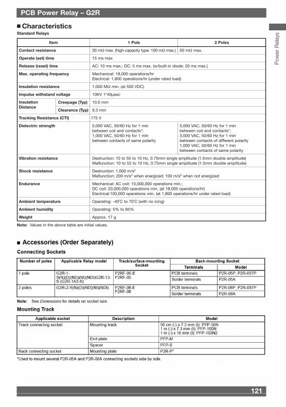
■ CharacteristicsStandard Relays
Item 1 Pole 2 Poles
Contact resistance 30 mΩ max. (high-capacity type: 100 mΩ max.) 50 mΩ max.
Operate (set) time 15 ms max
Release (reset) time AC: 10 ms max.; DC: 5 ms max. (w/built-in diode: 20 ms max.)
Max. operating frequency Mechanical: 18,000 operations/hrElectrical: 1,800 operations/hr (under rated load)
Insulation resistance 1,000 MΩ min. (at 500 VDC)
Impulse withstand voltage 10KV 1*40µsec
Creepage (Typ) 10.0 mm
Clearance (Typ) 9.3 mm
Tracking Resistance (CTI) 175 V
Dielectric strength 5,000 VAC, 50/60 Hz for 1 min 5,000 VAC, 50/60 Hz for 1 minbetween coil and contacts*; between coil and contacts*;1,000 VAC, 50/60 Hz for 1 min 3,000 VAC, 50/60 Hz for 1 minbetween contacts of same polarity between contacts of different polarity
1,000 VAC, 50/60 Hz for 1 minbetween contacts of same polarity
Vibration resistance Destruction: 10 to 55 to 10 Hz, 0.75mm single amplitude (1.5mm double amplitude)Malfunction: 10 to 55 to 10 Hz, 0.75mm single amplitude (1.5mm double amplitude)
Shock resistance Destruction: 1,000 m/s2
Malfunction: 200 m/s2 when energized; 100 m/s2 when not energized
Endurance Mechanical: AC coil: 10,000,000 operations min.; DC coil: 20,000,000 operations min. (at 18,000 operations/hr)Electrical:100,000 operations min. (at 1,800 operations/hr under rated load)
Ambient temperature Operating: -40˚C to 70˚C (with no icing)
Ambient humidity Operating: 5% to 85%
Weight Approx. 17 g
Note: Values in the above table are initial values.
PCB Power Relay – G2R
InsulationDistance
PCB Power Relay – G2R
Pow
er R
elay
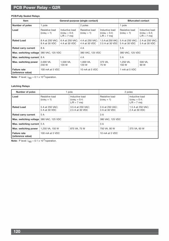
sItem General-purpose (single contact) Bifurcated contact
Number of poles 1 pole 2 poles 1 pole
Load Resistive load Inductive load Resistive load Inductive load Resistive load Inductive load(cosϕ = 1) (cosϕ = 0.4; (cosϕ = 1) (cosϕ = 0.4; (cosϕ = 1) (cosϕ = 0.4;
L/R = 7 ms) L/R = 7 ms) L/R = 7 ms)
Rated Load 8 A at 250 VAC; 6 A at 250 VAC; 4 A at 250 VAC; 1.5 A at 250 VAC; 5 A at 250 VAC; 2 A at 250 VAC;8 A at 30 VDC 4 A at 30 VDC 4 A at 30 VDC 2.5 A at 30 VDC 5 A at 30 VDC 3 A at 30 VDC
Rated carry current 8 A 4 A 5 A
Max. switching voltage 380 VAC, 125 VDC 380 VAC, 125 VDC 380 VAC, 125 VDC
Max. switching current 8 A 4 A 5 A
Max. switching power 2,000 VA, 1,500 VA, 1,000 VA, 375 VA, 1,250 VA, 500 VA,240 W 120 W 120 W 75 W 150 W 90 W
Failure rate 100 mA at 5 VDC 10 mA at 5 VDC 1 mA at 5 VDC(reference value)
Note: P level: λ60 = 0.1 x 10⁻⁶/operation.
PCB/Fully Sealed Relays
Number of poles 1 pole 2 poles
Load Resistive load Inductive load Resistive load Inductive load(cosϕ = 1) (cosϕ = 0.4; (cosϕ = 1) (cosϕ = 0.4;
L/R = 7 ms) L/R = 7 ms)
Rated Load 5 A at 250 VAC; 3.5 A at 250 VAC; 3 A at 250 VAC; 1.5 A at 250 VAC;5 A at 30 VDC 2.5 A at 30 VDC 3 A at 30 VDC 2 A at 30 VDC
Rated carry current 5 A 3 A
Max. switching voltage 380 VAC, 125 VDC 380 VAC, 125 VDC
Max. switching current 5 A 3 A
Max. switching power 1,250 VA, 150 W 875 VA, 75 W 750 VA, 90 W 375 VA, 60 W
Failure rate 100 mA at 5 VDC 10 mA at 5 VDC(reference value)
Note: P level: λ60 = 0.1 x 10⁻⁶/operation.
Latching Relays
Omron 08 Cat 1-302 5/10/07 15:39 Page 120
121
Text
120
Text
■ CharacteristicsStandard Relays
Item 1 Pole 2 Poles
Contact resistance 30 mΩ max. (high-capacity type: 100 mΩ max.) 50 mΩ max.
Operate (set) time 15 ms max
Release (reset) time AC: 10 ms max.; DC: 5 ms max. (w/built-in diode: 20 ms max.)
Max. operating frequency Mechanical: 18,000 operations/hrElectrical: 1,800 operations/hr (under rated load)
Insulation resistance 1,000 MΩ min. (at 500 VDC)
Impulse withstand voltage 10KV 1*40µsec
Creepage (Typ) 10.0 mm
Clearance (Typ) 9.3 mm
Tracking Resistance (CTI) 175 V
Dielectric strength 5,000 VAC, 50/60 Hz for 1 min 5,000 VAC, 50/60 Hz for 1 minbetween coil and contacts*; between coil and contacts*;1,000 VAC, 50/60 Hz for 1 min 3,000 VAC, 50/60 Hz for 1 minbetween contacts of same polarity between contacts of different polarity
1,000 VAC, 50/60 Hz for 1 minbetween contacts of same polarity
Vibration resistance Destruction: 10 to 55 to 10 Hz, 0.75mm single amplitude (1.5mm double amplitude)Malfunction: 10 to 55 to 10 Hz, 0.75mm single amplitude (1.5mm double amplitude)
Shock resistance Destruction: 1,000 m/s2
Malfunction: 200 m/s2 when energized; 100 m/s2 when not energized
Endurance Mechanical: AC coil: 10,000,000 operations min.; DC coil: 20,000,000 operations min. (at 18,000 operations/hr)Electrical:100,000 operations min. (at 1,800 operations/hr under rated load)
Ambient temperature Operating: -40˚C to 70˚C (with no icing)
Ambient humidity Operating: 5% to 85%
Weight Approx. 17 g
Note: Values in the above table are initial values.
PCB Power Relay – G2R
InsulationDistance
PCB Power Relay – G2R
Pow
er R
elay
sItem General-purpose (single contact) Bifurcated contact
Number of poles 1 pole 2 poles 1 pole
Load Resistive load Inductive load Resistive load Inductive load Resistive load Inductive load(cosϕ = 1) (cosϕ = 0.4; (cosϕ = 1) (cosϕ = 0.4; (cosϕ = 1) (cosϕ = 0.4;
L/R = 7 ms) L/R = 7 ms) L/R = 7 ms)
Rated Load 8 A at 250 VAC; 6 A at 250 VAC; 4 A at 250 VAC; 1.5 A at 250 VAC; 5 A at 250 VAC; 2 A at 250 VAC;8 A at 30 VDC 4 A at 30 VDC 4 A at 30 VDC 2.5 A at 30 VDC 5 A at 30 VDC 3 A at 30 VDC
Rated carry current 8 A 4 A 5 A
Max. switching voltage 380 VAC, 125 VDC 380 VAC, 125 VDC 380 VAC, 125 VDC
Max. switching current 8 A 4 A 5 A
Max. switching power 2,000 VA, 1,500 VA, 1,000 VA, 375 VA, 1,250 VA, 500 VA,240 W 120 W 120 W 75 W 150 W 90 W
Failure rate 100 mA at 5 VDC 10 mA at 5 VDC 1 mA at 5 VDC(reference value)
Note: P level: λ60 = 0.1 x 10⁻⁶/operation.
PCB/Fully Sealed Relays
Number of poles 1 pole 2 poles
Load Resistive load Inductive load Resistive load Inductive load(cosϕ = 1) (cosϕ = 0.4; (cosϕ = 1) (cosϕ = 0.4;
L/R = 7 ms) L/R = 7 ms)
Rated Load 5 A at 250 VAC; 3.5 A at 250 VAC; 3 A at 250 VAC; 1.5 A at 250 VAC;5 A at 30 VDC 2.5 A at 30 VDC 3 A at 30 VDC 2 A at 30 VDC
Rated carry current 5 A 3 A
Max. switching voltage 380 VAC, 125 VDC 380 VAC, 125 VDC
Max. switching current 5 A 3 A
Max. switching power 1,250 VA, 150 W 875 VA, 75 W 750 VA, 90 W 375 VA, 60 W
Failure rate 100 mA at 5 VDC 10 mA at 5 VDC(reference value)
Note: P level: λ60 = 0.1 x 10⁻⁶/operation.
Latching Relays
Omron 08 Cat 1-302 5/10/07 15:39 Page 120
123
Text
122
Text PCB Power Relay – G2R
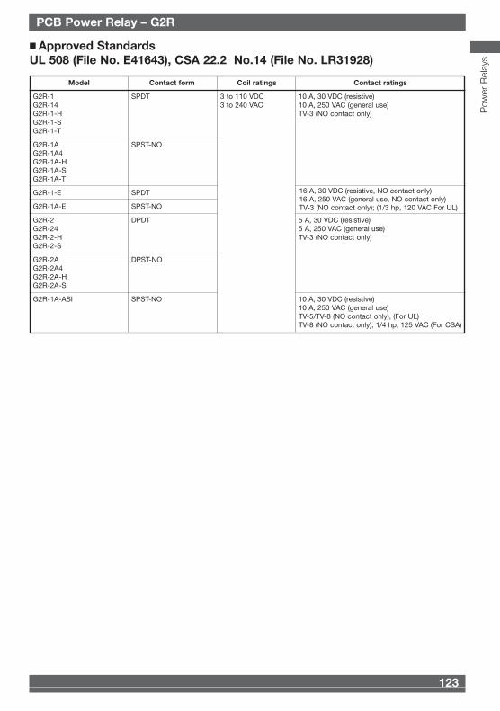
Model Contact form Coil ratings Contact ratings
G2R-1 SPDT 3 to 110 VDC 10 A, 30 VDC (resistive)G2R-14 3 to 240 VAC 10 A, 250 VAC (general use)G2R-1-H TV-3 (NO contact only)G2R-1-SG2R-1-T
G2R-1A SPST-NOG2R-1A4G2R-1A-HG2R-1A-SG2R-1A-T
G2R-1-E SPDT
G2R-1A-E SPST-NO
G2R-2 DPDT 5 A, 30 VDC (resistive)G2R-24 5 A, 250 VAC (general use)G2R-2-H TV-3 (NO contact only)G2R-2-S
G2R-2A DPST-NOG2R-2A4G2R-2A-HG2R-2A-S
G2R-1A-ASI SPST-NO 10 A, 30 VDC (resistive)10 A, 250 VAC (general use)TV-5/TV-8 (NO contact only), (For UL)TV-8 (NO contact only); 1/4 hp, 125 VAC (For CSA)
■ Approved StandardsUL 508 (File No. E41643), CSA 22.2 No.14 (File No. LR31928)
16 A, 30 VDC (resistive, NO contact only)16 A, 250 VAC (general use, NO contact only)TV-3 (NO contact only); (1/3 hp, 120 VAC For UL)
PCB Power Relay – G2R
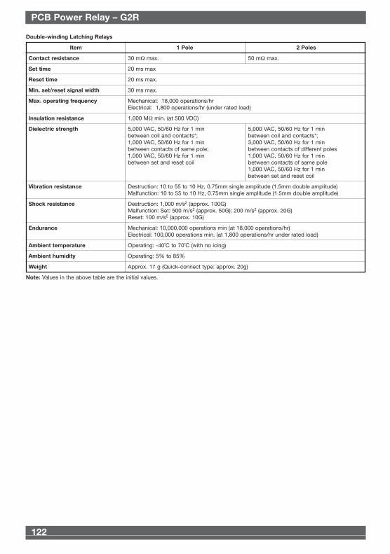
Double-winding Latching Relays
Item 1 Pole 2 Poles
Contact resistance 30 mΩ max. 50 mΩ max.
Set time 20 ms max
Reset time 20 ms max.
Min. set/reset signal width 30 ms max.
Max. operating frequency Mechanical: 18,000 operations/hrElectrical: 1,800 operations/hr (under rated load)
Insulation resistance 1,000 MΩ min. (at 500 VDC)
Dielectric strength 5,000 VAC, 50/60 Hz for 1 min 5,000 VAC, 50/60 Hz for 1 minbetween coil and contacts*; between coil and contacts*;1,000 VAC, 50/60 Hz for 1 min 3,000 VAC, 50/60 Hz for 1 minbetween contacts of same pole; between contacts of different poles1,000 VAC, 50/60 Hz for 1 min 1,000 VAC, 50/60 Hz for 1 minbetween set and reset coil between contacts of same pole
1,000 VAC, 50/60 Hz for 1 minbetween set and reset coil
Vibration resistance Destruction: 10 to 55 to 10 Hz, 0.75mm single amplitude (1.5mm double amplitude)Malfunction: 10 to 55 to 10 Hz, 0.75mm single amplitude (1.5mm double amplitude)
Shock resistance Destruction: 1,000 m/s2 (approx. 100G)Malfunction: Set: 500 m/s2 (approx. 50G); 200 m/s2 (approx. 20G)Reset: 100 m/s2 (approx. 10G)
Endurance Mechanical: 10,000,000 operations min (at 18,000 operations/hr)Electrical: 100,000 operations min. (at 1,800 operations/hr under rated load)
Ambient temperature Operating: -40˚C to 70˚C (with no icing)
Ambient humidity Operating: 5% to 85%
Weight Approx. 17 g (Quick-connect type: approx. 20g)
Note: Values in the above table are the initial values.
Pow
er R
elay
s
Omron 08 Cat 1-302 5/10/07 15:39 Page 122
123
Text
122
Text PCB Power Relay – G2R
Model Contact form Coil ratings Contact ratings
G2R-1 SPDT 3 to 110 VDC 10 A, 30 VDC (resistive)G2R-14 3 to 240 VAC 10 A, 250 VAC (general use)G2R-1-H TV-3 (NO contact only)G2R-1-SG2R-1-T
G2R-1A SPST-NOG2R-1A4G2R-1A-HG2R-1A-SG2R-1A-T
G2R-1-E SPDT
G2R-1A-E SPST-NO
G2R-2 DPDT 5 A, 30 VDC (resistive)G2R-24 5 A, 250 VAC (general use)G2R-2-H TV-3 (NO contact only)G2R-2-S
G2R-2A DPST-NOG2R-2A4G2R-2A-HG2R-2A-S
G2R-1A-ASI SPST-NO 10 A, 30 VDC (resistive)10 A, 250 VAC (general use)TV-5/TV-8 (NO contact only), (For UL)TV-8 (NO contact only); 1/4 hp, 125 VAC (For CSA)
■ Approved StandardsUL 508 (File No. E41643), CSA 22.2 No.14 (File No. LR31928)
16 A, 30 VDC (resistive, NO contact only)16 A, 250 VAC (general use, NO contact only)TV-3 (NO contact only); (1/3 hp, 120 VAC For UL)
PCB Power Relay – G2R
Double-winding Latching Relays
Item 1 Pole 2 Poles
Contact resistance 30 mΩ max. 50 mΩ max.
Set time 20 ms max
Reset time 20 ms max.
Min. set/reset signal width 30 ms max.
Max. operating frequency Mechanical: 18,000 operations/hrElectrical: 1,800 operations/hr (under rated load)
Insulation resistance 1,000 MΩ min. (at 500 VDC)
Dielectric strength 5,000 VAC, 50/60 Hz for 1 min 5,000 VAC, 50/60 Hz for 1 minbetween coil and contacts*; between coil and contacts*;1,000 VAC, 50/60 Hz for 1 min 3,000 VAC, 50/60 Hz for 1 minbetween contacts of same pole; between contacts of different poles1,000 VAC, 50/60 Hz for 1 min 1,000 VAC, 50/60 Hz for 1 minbetween set and reset coil between contacts of same pole
1,000 VAC, 50/60 Hz for 1 minbetween set and reset coil
Vibration resistance Destruction: 10 to 55 to 10 Hz, 0.75mm single amplitude (1.5mm double amplitude)Malfunction: 10 to 55 to 10 Hz, 0.75mm single amplitude (1.5mm double amplitude)
Shock resistance Destruction: 1,000 m/s2 (approx. 100G)Malfunction: Set: 500 m/s2 (approx. 50G); 200 m/s2 (approx. 20G)Reset: 100 m/s2 (approx. 10G)
Endurance Mechanical: 10,000,000 operations min (at 18,000 operations/hr)Electrical: 100,000 operations min. (at 1,800 operations/hr under rated load)
Ambient temperature Operating: -40˚C to 70˚C (with no icing)
Ambient humidity Operating: 5% to 85%
Weight Approx. 17 g (Quick-connect type: approx. 20g)
Note: Values in the above table are the initial values.
Pow
er R
elay
s
Omron 08 Cat 1-302 5/10/07 15:39 Page 122
125
Text
124
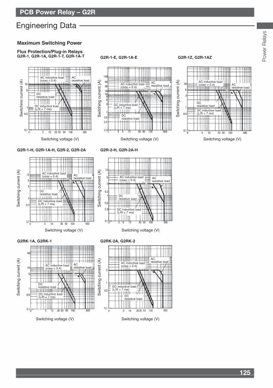
Text PCB Power Relay – G2R
Flux Protection/Plug-in RelaysG2R-1, G2R-1A, G2R-1-T, G2R-1A-T
Sw
itchi
ng c
urre
nt (
A)
G2R-1-E, G2R-1A-E G2R-1Z, G2R-1AZ
Switching voltage (V) Switching voltage (V) Switching voltage (V)
G2R-1-H, G2R-1A-H, G2R-2, G2R-2A G2R-2-H, G2R-2A-H
Switching voltage (V) Switching voltage (V)
G2RK-1A, G2RK-1 G2RK-2A, G2RK-2
Switching voltage (V) Switching voltage (V)
Maximum Switching Power
ACresistive load
DCresistive load
AC inductive load
DC inductive load (L/R = 7 ms)
ACresistive load
DC inductive load (L/R = 7 ms)
DCresistive load
AC inductive load ACresistive load
AC inductive load
DC inductive load (L/R = 7 ms)
DCresistive load
ACresistive load
DCresistive load
DC inductive load (L/R = 7 ms)
DC inductive load (L/R = 7 ms)
DCresistive load
ACresistive load
ACresistive load
ACresistive load
DCresistive load
DCresistive load
DC inductive load (L/R = 7 ms)
DC inductive load (L/R = 7 ms)
AC inductive load AC inductive load
AC inductive load AC inductive load
Sw
itchi
ng c
urre
nt (
A)
Sw
itchi
ng c
urre
nt (
A)
Sw
itchi
ng c
urre
nt (
A)
Sw
itchi
ng c
urre
nt (
A)
Sw
itchi
ng c
urre
nt (
A)
Sw
itchi
ng c
urre
nt (
A)
Engineering Data
PCB Power Relay – G2R
Contact form Coil ratings Contact ratings
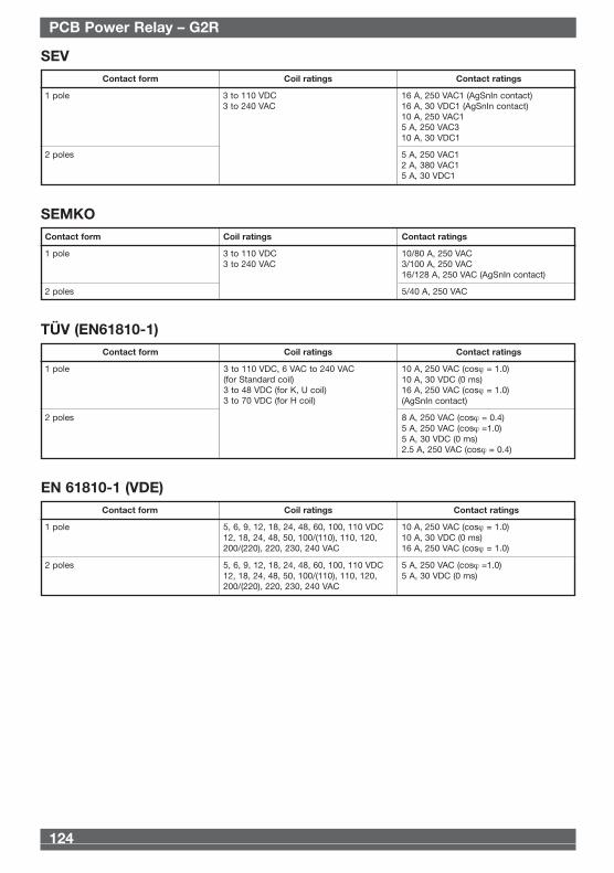
1 pole 3 to 110 VDC 16 A, 250 VAC1 (AgSnIn contact)3 to 240 VAC 16 A, 30 VDC1 (AgSnIn contact)
10 A, 250 VAC15 A, 250 VAC310 A, 30 VDC1
2 poles 5 A, 250 VAC12 A, 380 VAC15 A, 30 VDC1
SEV
Contact form Coil ratings Contact ratings
1 pole 5, 6, 9, 12, 18, 24, 48, 60, 100, 110 VDC 10 A, 250 VAC (cosϕ = 1.0)12, 18, 24, 48, 50, 100/(110), 110, 120, 10 A, 30 VDC (0 ms)200/(220), 220, 230, 240 VAC 16 A, 250 VAC (cosϕ = 1.0)
2 poles 5, 6, 9, 12, 18, 24, 48, 60, 100, 110 VDC 5 A, 250 VAC (cosϕ =1.0)12, 18, 24, 48, 50, 100/(110), 110, 120, 5 A, 30 VDC (0 ms)200/(220), 220, 230, 240 VAC
EN 61810-1 (VDE)
Contact form Coil ratings Contact ratings
1 pole 3 to 110 VDC 10/80 A, 250 VAC3 to 240 VAC 3/100 A, 250 VAC
16/128 A, 250 VAC (AgSnIn contact)
2 poles 5/40 A, 250 VAC
SEMKO
Contact form Coil ratings Contact ratings
1 pole 10 A, 250 VAC (cosϕ = 1.0)10 A, 30 VDC (0 ms)16 A, 250 VAC (cosϕ = 1.0)(AgSnIn contact)
2 poles 8 A, 250 VAC (cosϕ = 0.4)5 A, 250 VAC (cosϕ =1.0)5 A, 30 VDC (0 ms)2.5 A, 250 VAC (cosϕ = 0.4)
TÜV (EN61810-1)
3 to 110 VDC, 6 VAC to 240 VAC(for Standard coil)3 to 48 VDC (for K, U coil)3 to 70 VDC (for H coil)
Pow
er R
elay
s
s Contact ratings
10 A, 30 VDC (resistive)10 A, 250 VAC (general use)TV-3 (NO contact only)
5 A, 30 VDC (resistive)5 A, 250 VAC (general use)TV-3 (NO contact only)
10 A, 30 VDC (resistive)10 A, 250 VAC (general use)TV-8 (NO contact only); 1/4 hp, 125 VAC
16 A, 30 VDC (resistive, NO contact only)16 A, 250 VAC (general use, NO contact only)TV-3 (NO contact only)
Omron 08 Cat 1-302 5/10/07 15:39 Page 124
125
Text
124
Text PCB Power Relay – G2R
Flux Protection/Plug-in RelaysG2R-1, G2R-1A, G2R-1-T, G2R-1A-T
Sw
itchi
ng c
urre
nt (
A)
G2R-1-E, G2R-1A-E G2R-1Z, G2R-1AZ
Switching voltage (V) Switching voltage (V) Switching voltage (V)
G2R-1-H, G2R-1A-H, G2R-2, G2R-2A G2R-2-H, G2R-2A-H
Switching voltage (V) Switching voltage (V)
G2RK-1A, G2RK-1 G2RK-2A, G2RK-2
Switching voltage (V) Switching voltage (V)
Maximum Switching Power
ACresistive load
DCresistive load
AC inductive load
DC inductive load (L/R = 7 ms)
ACresistive load
DC inductive load (L/R = 7 ms)
DCresistive load
AC inductive load ACresistive load
AC inductive load
DC inductive load (L/R = 7 ms)
DCresistive load
ACresistive load
DCresistive load
DC inductive load (L/R = 7 ms)
DC inductive load (L/R = 7 ms)
DCresistive load
ACresistive load
ACresistive load
ACresistive load
DCresistive load
DCresistive load
DC inductive load (L/R = 7 ms)
DC inductive load (L/R = 7 ms)
AC inductive load AC inductive load
AC inductive load AC inductive load
Sw
itchi
ng c
urre
nt (
A)
Sw
itchi
ng c
urre
nt (
A)
Sw
itchi
ng c
urre
nt (
A)
Sw
itchi
ng c
urre
nt (
A)
Sw
itchi
ng c
urre
nt (
A)
Sw
itchi
ng c
urre
nt (
A)
Engineering Data
PCB Power Relay – G2R
Contact form Coil ratings Contact ratings
1 pole 3 to 110 VDC 16 A, 250 VAC1 (AgSnIn contact)3 to 240 VAC 16 A, 30 VDC1 (AgSnIn contact)
10 A, 250 VAC15 A, 250 VAC310 A, 30 VDC1
2 poles 5 A, 250 VAC12 A, 380 VAC15 A, 30 VDC1
SEV
Contact form Coil ratings Contact ratings
1 pole 5, 6, 9, 12, 18, 24, 48, 60, 100, 110 VDC 10 A, 250 VAC (cosϕ = 1.0)12, 18, 24, 48, 50, 100/(110), 110, 120, 10 A, 30 VDC (0 ms)200/(220), 220, 230, 240 VAC 16 A, 250 VAC (cosϕ = 1.0)
2 poles 5, 6, 9, 12, 18, 24, 48, 60, 100, 110 VDC 5 A, 250 VAC (cosϕ =1.0)12, 18, 24, 48, 50, 100/(110), 110, 120, 5 A, 30 VDC (0 ms)200/(220), 220, 230, 240 VAC
EN 61810-1 (VDE)
Contact form Coil ratings Contact ratings
1 pole 3 to 110 VDC 10/80 A, 250 VAC3 to 240 VAC 3/100 A, 250 VAC
16/128 A, 250 VAC (AgSnIn contact)
2 poles 5/40 A, 250 VAC
SEMKO
Contact form Coil ratings Contact ratings
1 pole 10 A, 250 VAC (cosϕ = 1.0)10 A, 30 VDC (0 ms)16 A, 250 VAC (cosϕ = 1.0)(AgSnIn contact)
2 poles 8 A, 250 VAC (cosϕ = 0.4)5 A, 250 VAC (cosϕ =1.0)5 A, 30 VDC (0 ms)2.5 A, 250 VAC (cosϕ = 0.4)
TÜV (EN61810-1)
3 to 110 VDC, 6 VAC to 240 VAC(for Standard coil)3 to 48 VDC (for K, U coil)3 to 70 VDC (for H coil)
Pow
er R
elay
s
s Contact ratings
10 A, 30 VDC (resistive)10 A, 250 VAC (general use)TV-3 (NO contact only)
5 A, 30 VDC (resistive)5 A, 250 VAC (general use)TV-3 (NO contact only)
10 A, 30 VDC (resistive)10 A, 250 VAC (general use)TV-8 (NO contact only); 1/4 hp, 125 VAC
16 A, 30 VDC (resistive, NO contact only)16 A, 250 VAC (general use, NO contact only)TV-3 (NO contact only)
Omron 08 Cat 1-302 5/10/07 15:39 Page 124
127
Text
126
Text PCB Power Relay – G2R
G2RK-1A, G2RK-1 G2RK-2A, G2RK-2
End
uran
ce (
x10
ope
ratio
ns)
3
Switching current (A) Switching current (A)
Fully sealed RelaysG2R-14, G2R-1A4 G2R-24, G2R-2A4 G2R-1Z4, G2R-1AZ4
Switching current (A) Switching current (A) Switching current (A)
30-VDC inductive load (L/R = 7ms)
250-VAC/30-VDCresistive load
250-VAC inductive load (cosφ = 0.4)
250-VAC/30-VDCresistive load30-VDC inductive load (L/R = 7 ms)
250-VAC inductive load (cosφ = 0.4)
250-VAC/30-VDCresistive load
250-VAC/30-VDCresistive load
250-VAC/30-VDCresistive load
250-VAC inductive load (cosφ = 0.4)
250-VAC inductive load (cosφ = 0.4)
250-VAC inductive load (cosφ = 0.4)
30-VDC inductive load (L/R = 7ms)
30-VDC inductive load (L/R = 7 ms)
30-VDC inductive load (L/R = 7 ms)
5,000
1,000
500
100
50
End
uran
ce (
x10
ope
ratio
ns)
3
End
uran
ce (
x10
ope
ratio
ns)
3
End
uran
ce (
x10
ope
ratio
ns)
3
End
uran
ce (
x10
ope
ratio
ns)
3
10,0005,000
1,000500
10050
5,000
1,000
500
100
50
5,000
1,000
500
100
50
5,000
1,000
500
100
50
Ambient temperature (°C)
Max
imum
coi
l vol
tage
(%
)
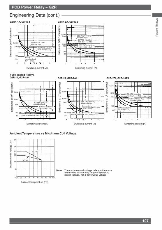
Ambient Temperature vs Maximum Coil Voltage
DC coil
AC coil
Note: The maximum coil voltage refers to the maxi-mum value in a varying range of operating power voltage, not a continuous voltage.
Engineering Data (cont.)
PCB Power Relay – G2R
Flux Protection/Plug-in RelaysG2R-1, G2R-1A, G2R-1-T, G2R-1A-T
End
uran
ce (
x10
ope
ratio
ns)
3
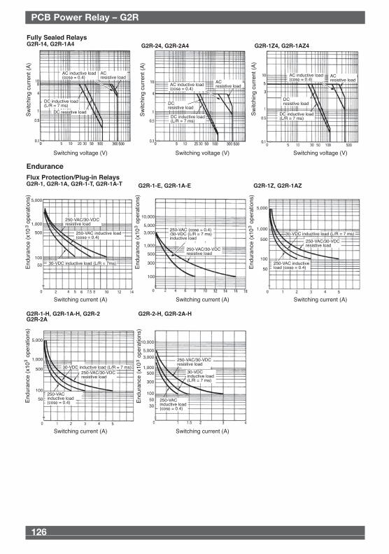
G2R-1-E, G2R-1A-E G2R-1Z, G2R-1AZ
Switching current (A) Switching current (A) Switching current (A)
G2R-1-H, G2R-1A-H, G2R-2 G2R-2A
G2R-2-H, G2R-2A-H
Switching current (A) Switching current (A)
Endurance
250-VAC/30-VDCresistive load
250-VAC inductive load (cosφ = 0.4)
30-VDC inductive load (L/R = 7ms)
250-VAC/30-VDCresistive load
250-VAC (cosφ = 0.4)/30-VDC (L/R = 7 ms) inductive load
30-VDC inductive load (L/R = 7 ms)
250-VAC/30-VDC resistive load
250-VAC inductive load (cosφ = 0.4)
30-VDC inductive load (L/R = 7 ms)30-VDC inductive load (L/R = 7 ms)
250-VAC/30-VDCresistive load
250-VAC/30-VDCresistive load
250-VAC inductive load (cosφ = 0.4) 250-VAC
inductive load (cosφ = 0.4)
5,000
1,000
500
100
50 End
uran
ce (
x10
ope
ratio
ns)
3
End
uran
ce (
x10
ope
ratio
ns)
3
End
uran
ce (
x10
ope
ratio
ns)
3
End
uran
ce (
x10
ope
ratio
ns)
3
5,000
1,000
500
100
50
5,000
1,000
500
100
50
10,000
5,000
3,000
1,000
500
300
100
10,000
5,000
3,000
1,000500
300
100 50
30
G2R-13-S, G2R-1A3-S
Fully Sealed RelaysG2R-14, G2R-1A4
Switching voltage (V) Switching voltage (V) Switching voltage (V)
ACresistive load
AC inductive load (cosφ = 0.4)
DC resistive load
DC inductive load (L/R = 7 ms)
ACresistive load
DC inductive load (L/R = 7 ms)
DCresistive load
ACresistive load
DC inductive load (L/R = 7 ms)
DCresistive load
AC inductive load (cosφ = 0.4)
AC inductive load (cosφ = 0.4)
Sw
itchi
ng c
urre
nt (
A)
Sw
itchi
ng c
urre
nt (
A)
Sw
itchi
ng c
urre
nt (
A)
G2R-24, G2R-2A4 G2R-1Z4, G2R-1AZ4
Pow
er R
elay
s
Omron 08 Cat 1-302 5/10/07 15:39 Page 126
127
Text
126
Text PCB Power Relay – G2R
G2RK-1A, G2RK-1 G2RK-2A, G2RK-2
End
uran
ce (
x10
ope
ratio
ns)
3
Switching current (A) Switching current (A)
Fully sealed RelaysG2R-14, G2R-1A4 G2R-24, G2R-2A4 G2R-1Z4, G2R-1AZ4
Switching current (A) Switching current (A) Switching current (A)
30-VDC inductive load (L/R = 7ms)
250-VAC/30-VDCresistive load
250-VAC inductive load (cosφ = 0.4)
250-VAC/30-VDCresistive load30-VDC inductive load (L/R = 7 ms)
250-VAC inductive load (cosφ = 0.4)
250-VAC/30-VDCresistive load
250-VAC/30-VDCresistive load
250-VAC/30-VDCresistive load
250-VAC inductive load (cosφ = 0.4)
250-VAC inductive load (cosφ = 0.4)
250-VAC inductive load (cosφ = 0.4)
30-VDC inductive load (L/R = 7ms)
30-VDC inductive load (L/R = 7 ms)
30-VDC inductive load (L/R = 7 ms)
5,000
1,000
500
100
50E
ndur
ance
(x1
0 o
pera
tions
)3
End
uran
ce (
x10
ope
ratio
ns)
3
End
uran
ce (
x10
ope
ratio
ns)
3
End
uran
ce (
x10
ope
ratio
ns)
3
10,0005,000
1,000500
10050
5,000
1,000
500
100
50
5,000
1,000
500
100
50
5,000
1,000
500
100
50
Ambient temperature (°C)
Max
imum
coi
l vol
tage
(%
)
Ambient Temperature vs Maximum Coil Voltage
DC coil
AC coil
Note: The maximum coil voltage refers to the maxi-mum value in a varying range of operating power voltage, not a continuous voltage.
Engineering Data (cont.)
PCB Power Relay – G2R
Flux Protection/Plug-in RelaysG2R-1, G2R-1A, G2R-1-T, G2R-1A-T
End
uran
ce (
x10
ope
ratio
ns)
3
G2R-1-E, G2R-1A-E G2R-1Z, G2R-1AZ
Switching current (A) Switching current (A) Switching current (A)
G2R-1-H, G2R-1A-H, G2R-2 G2R-2A
G2R-2-H, G2R-2A-H
Switching current (A) Switching current (A)
Endurance
250-VAC/30-VDCresistive load
250-VAC inductive load (cosφ = 0.4)
30-VDC inductive load (L/R = 7ms)
250-VAC/30-VDCresistive load
250-VAC (cosφ = 0.4)/30-VDC (L/R = 7 ms) inductive load
30-VDC inductive load (L/R = 7 ms)
250-VAC/30-VDC resistive load
250-VAC inductive load (cosφ = 0.4)
30-VDC inductive load (L/R = 7 ms)30-VDC inductive load (L/R = 7 ms)
250-VAC/30-VDCresistive load
250-VAC/30-VDCresistive load
250-VAC inductive load (cosφ = 0.4) 250-VAC
inductive load (cosφ = 0.4)
5,000
1,000
500
100
50 End
uran
ce (
x10
ope
ratio
ns)
3
End
uran
ce (
x10
ope
ratio
ns)
3
End
uran
ce (
x10
ope
ratio
ns)
3
End
uran
ce (
x10
ope
ratio
ns)
3
5,000
1,000
500
100
50
5,000
1,000
500
100
50
10,000
5,000
3,000
1,000
500
300
100
10,000
5,000
3,000
1,000500
300
100 50
30
G2R-13-S, G2R-1A3-S
Fully Sealed RelaysG2R-14, G2R-1A4
Switching voltage (V) Switching voltage (V) Switching voltage (V)
ACresistive load
AC inductive load (cosφ = 0.4)
DC resistive load
DC inductive load (L/R = 7 ms)
ACresistive load
DC inductive load (L/R = 7 ms)
DCresistive load
ACresistive load
DC inductive load (L/R = 7 ms)
DCresistive load
AC inductive load (cosφ = 0.4)
AC inductive load (cosφ = 0.4)
Sw
itchi
ng c
urre
nt (
A)
Sw
itchi
ng c
urre
nt (
A)
Sw
itchi
ng c
urre
nt (
A)
G2R-24, G2R-2A4 G2R-1Z4, G2R-1AZ4
Pow
er R
elay
s
Omron 08 Cat 1-302 5/10/07 15:39 Page 126
129
Text
128
Text PCB Power Relay – G2R
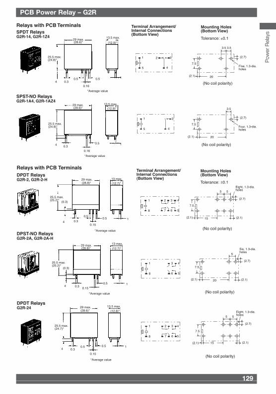
Relays with PCB TerminalsSPDT RelaysG2R-14, G2R-1Z4
Mounting Holes (Bottom View)
Terminal Arrangement/Internal Connections (Bottom View)
Tolerance: ±0.1
SPST-NO RelaysG2R-1A4, G2R-1AZ4
29 max.13.5 max.
25.5 max.(24.8)*
4 0.30.5 0.5
0.16
1
29 max.
25.5 max.(24.8)*
13.5 max.
4 0.30.5
0.16
1
20
7.5
3.5 3.5
(2.1)
(2.7)
Five, 1.3-dia.holes
20
7.5
3.5
(2.1)
(2.7)
Four, 1.3-dia.holes
1
5
2 3
4
1
5
3
4
(28.6)* (12.9)*
*Average value
(No coil polarity)
(28.6)* (12.9)*
*Average value
(No coil polarity)
Relays with PCB TerminalsDPDT RelaysG2R-2, G2R-2-H
Mounting Holes (Bottom View)
Terminal Arrangement/Internal Connections (Bottom View)
Tolerance: ±0.1
DPST-NO RelaysG2R-2A, G2R-2A-H
DPDT Relays
29 max.
25.5 max.
(0.3)
13 max.
4 0.3
0.50.5
0.15
1
29 max. 13 max.
25.5 max.(25.2)*
(0.3)
0.340.15
0.5 1
15
5 5
7.5
(2.7)
(2.1)(2.1)
Eight, 1.3-dia.holes
20
5
7.5
(2.7)
(2.1)(2.1)
Six, 1.3-dia.holes
1
8
3 42
6 57
1
8
3 4
6 5
(25.2)*
(28.8)* (12.7)*
(12.7)*
*Average value
*Average value
(28.8)*
(No coil polarity)
(No coil polarity)
DPDT RelaysG2R-24 29 max. 13.5 max.
25.5 max.(24.7)*
4 0.30.5 0.5
0.15
115
5 5
7.5
(2.7)
(2.1)(2.1)
Eight, 1.3-dia.holes
1
8
3 42
6 57
g
*Average value
(12.8)*(28.6)*
(No coil polarity)
PCB Power Relay – G2R
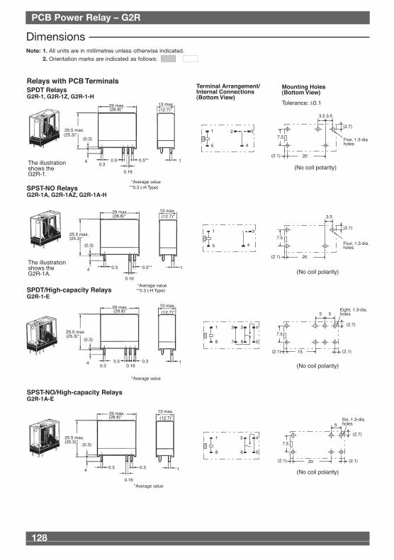
DimensionsNote: 1. All units are in millimetres unless otherwise indicated.
2. Orientation marks are indicated as follows:
Relays with PCB TerminalsSPDT RelaysG2R-1, G2R-1Z, G2R-1-H
Mounting Holes (Bottom View)
Terminal Arrangement/Internal Connections (Bottom View)
Tolerance: ±0.1
The illustration shows the G2R-1.
SPST-NO RelaysG2R-1A, G2R-1AZ, G2R-1A-H
SPDT/High-capacity RelaysG2R-1-E
SPST-NO/High-capacity RelaysG2R-1A-E
The illustration shows the G2R-1A.
29 max. 13 max.
25.5 max.
(0.3)
0.34 0.5 0.5**
0.16
1
29 max.
25.5 max.(25.3)*
(0.3)
4 0.5**0.3
0.16
13 max.
1
29 max.
25.5 max.(25.3)*
(0.3)
4 0.5 0.30.3 0.16
13 max.
1
29 max.
25.5 max.(25.3)*
(0.3)
40.30.3
0.16
13 max.
1
20
7.5
3.5 3.5
(2.1)
(2.7)
Five, 1.3-dia.holes
20
7.5
3.5
(2.1)
(2.7)
Four, 1.3-dia.holes
20
5
7.5
(2.7)
(2.1)(2.1)
Six, 1.3-dia.holes
15
5 5
7.5
(2.7)
(2.1)(2.1)
Eight, 1.3-dia.holes
1
5
2 3
4
1
5
3
4
1
8
2 3 4
567
1
8
3 4
56
(25.3)*
(28.8)* (12.7)*
*Average value
(No coil polarity)
(No coil polarity)
(No coil polarity)
(No coil polarity)
*Average value
*Average value
*Average value
(28.8)*
(28.8)*
(28.8)*
(12.7)*
(12.7)*
(12.7)*
**0.3 (-H Type)
**0.3 (-H Type)
Pow
er R
elay
s
Omron 08 Cat 1-302 5/10/07 15:39 Page 128
129
Text
128
Text PCB Power Relay – G2R
Relays with PCB TerminalsSPDT RelaysG2R-14, G2R-1Z4
Mounting Holes (Bottom View)
Terminal Arrangement/Internal Connections (Bottom View)
Tolerance: ±0.1
SPST-NO RelaysG2R-1A4, G2R-1AZ4
29 max.13.5 max.
25.5 max.(24.8)*
4 0.30.5 0.5
0.16
1
29 max.
25.5 max.(24.8)*
13.5 max.
4 0.30.5
0.16
1
20
7.5
3.5 3.5
(2.1)
(2.7)
Five, 1.3-dia.holes
20
7.5
3.5
(2.1)
(2.7)
Four, 1.3-dia.holes
1
5
2 3
4
1
5
3
4
(28.6)* (12.9)*
*Average value
(No coil polarity)
(28.6)* (12.9)*
*Average value
(No coil polarity)
Relays with PCB TerminalsDPDT RelaysG2R-2, G2R-2-H
Mounting Holes (Bottom View)
Terminal Arrangement/Internal Connections (Bottom View)
Tolerance: ±0.1
DPST-NO RelaysG2R-2A, G2R-2A-H
DPDT Relays
29 max.
25.5 max.
(0.3)
13 max.
4 0.3
0.50.5
0.15
1
29 max. 13 max.
25.5 max.(25.2)*
(0.3)
0.340.15
0.5 1
15
5 5
7.5
(2.7)
(2.1)(2.1)
Eight, 1.3-dia.holes
20
5
7.5
(2.7)
(2.1)(2.1)
Six, 1.3-dia.holes
1
8
3 42
6 57
1
8
3 4
6 5
(25.2)*
(28.8)* (12.7)*
(12.7)*
*Average value
*Average value
(28.8)*
(No coil polarity)
(No coil polarity)
DPDT RelaysG2R-24 29 max. 13.5 max.
25.5 max.(24.7)*
4 0.30.5 0.5
0.15
115
5 5
7.5
(2.7)
(2.1)(2.1)
Eight, 1.3-dia.holes
1
8
3 42
6 57
g
*Average value
(12.8)*(28.6)*
(No coil polarity)
PCB Power Relay – G2R
DimensionsNote: 1. All units are in millimetres unless otherwise indicated.
2. Orientation marks are indicated as follows:
Relays with PCB TerminalsSPDT RelaysG2R-1, G2R-1Z, G2R-1-H
Mounting Holes (Bottom View)
Terminal Arrangement/Internal Connections (Bottom View)
Tolerance: ±0.1
The illustration shows the G2R-1.
SPST-NO RelaysG2R-1A, G2R-1AZ, G2R-1A-H
SPDT/High-capacity RelaysG2R-1-E
SPST-NO/High-capacity RelaysG2R-1A-E
The illustration shows the G2R-1A.
29 max. 13 max.
25.5 max.
(0.3)
0.34 0.5 0.5**
0.16
1
29 max.
25.5 max.(25.3)*
(0.3)
4 0.5**0.3
0.16
13 max.
1
29 max.
25.5 max.(25.3)*
(0.3)
4 0.5 0.30.3 0.16
13 max.
1
29 max.
25.5 max.(25.3)*
(0.3)
40.30.3
0.16
13 max.
1
20
7.5
3.5 3.5
(2.1)
(2.7)
Five, 1.3-dia.holes
20
7.5
3.5
(2.1)
(2.7)
Four, 1.3-dia.holes
20
5
7.5
(2.7)
(2.1)(2.1)
Six, 1.3-dia.holes
15
5 5
7.5
(2.7)
(2.1)(2.1)
Eight, 1.3-dia.holes
1
5
2 3
4
1
5
3
4
1
8
2 3 4
567
1
8
3 4
56
(25.3)*
(28.8)* (12.7)*
*Average value
(No coil polarity)
(No coil polarity)
(No coil polarity)
(No coil polarity)
*Average value
*Average value
*Average value
(28.8)*
(28.8)*
(28.8)*
(12.7)*
(12.7)*
(12.7)*
**0.3 (-H Type)
**0.3 (-H Type)
Pow
er R
elay
s
Omron 08 Cat 1-302 5/10/07 15:39 Page 128
131
Text
130
Text PCB Power Relay – G2R
SPDT RelaysG2R-1-T
Relays with Quick-connect Terminals
SPST-NO RelaysG2R-1A-T
Note: Model number of quick-connect terminal is 187.
30.5 max.
7.5
5.2 5.217.4
Five, 1.3-dia. holes4.75 0.5
8.5
29.5 max.
2.5
45 max.14 max.
30.5 max.
7.5
17.45.2
Five, 1.3-dia. holes4.75 0.5
8.5
29.5 max.
2.5
45 max.14 max.
Mounting Holes (Bottom View)Tolerance: ±0.1
38 Two M3 or two 3.5 dia.
Terminal Arrangement/Internal Connections (Bottom View)
Mounting Holes (Bottom View)
Terminal Arrangement/Internal Connections (Bottom View)
38Two M3 or two 3.5 dia.
1
54 32
1
54 3
(No coil polarity)
(No coil polarity)
*Average value
(29.7)*
(13.1)*(43.9)*
(43.9)* (13.1)*
(29.7)*
*Average value
Precautions■ MountingWhen mounting a number of relays on a PCB, be sure to providea minimum mounting space of 5 mm between the two juxtaposedrelays as shown below.
The above minimum mounting space is necessary due to mutualthermal interference generated by the relays. This restriction maybe ignored, however, depending on the operating conditions ofthe relays. Consult OMRON for details.There is no restriction on the mounting direction of each relay onthe PCB.When using this circuit, confirm the set and reset states and thentake into account the circuit constant.5 mm min.
5 mm min.
CAT. No. K013-E2-12A-X
PCB Power Relay – G2R
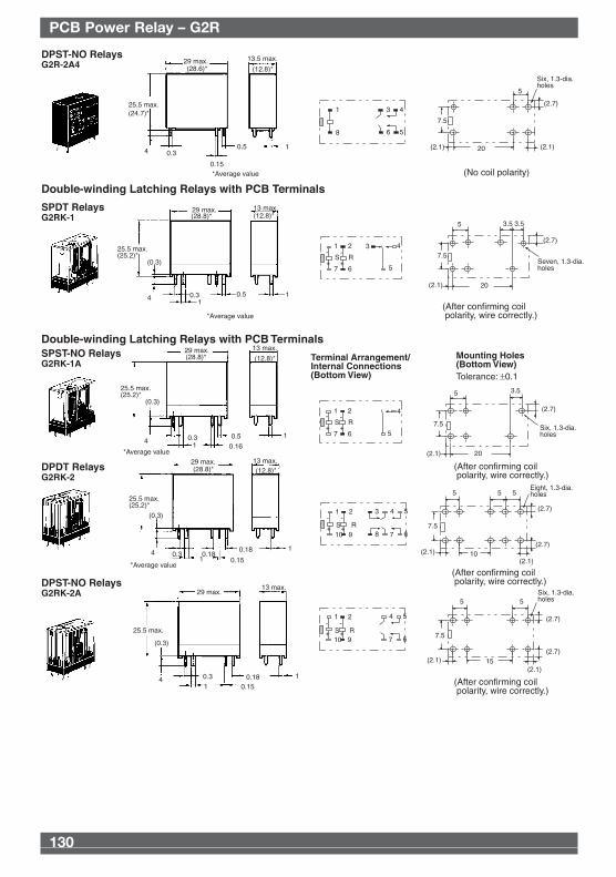
DPST-NO RelaysG2R-2A4
Double-winding Latching Relays with PCB Terminals
SPDT RelaysG2RK-1
29 max. 13.5 max.
25.5 max.
4 0.3
0.15
0.5 1
29 max. 13 max.
25.5 max.(25.2)*
4
(0.3)
0.31
0.5 1
20
5
7.5
(2.7)
(2.1)(2.1)
Six, 1.3-dia.holes
20
7.5
3.5 3.5
(2.1)
Seven, 1.3-dia.holes
5
(2.7)
1
8
3 4
6 5
1
7
3 4
5
2
6
S R+
-
+
-
*Average value
*Average value
(24.7)*
(28.8)* (12.8)*
(12.8)*(28.6)*
(No coil polarity)
(After confirming coil polarity, wire correctly.)
Double-winding Latching Relays with PCB TerminalsSPST-NO RelaysG2RK-1A
Mounting Holes (Bottom View)
Terminal Arrangement/Internal Connections (Bottom View) Tolerance: ±0.1
DPDT RelaysG2RK-2
DPST-NO RelaysG2RK-2A
29 max. 13 max.
25.5 max.(25.2)*
(0.3)
4 0.3 0.51 0.16
1
29 max. 13 max.
25.5 max.(25.2)*
(0.3)
4 0.3 0.180.18 1
1 0.15
29 max.13 max.
25.5 max.
(0.3)
4 0.3 0.18 1
1 0.15
20
7.5
3.5
(2.1)
(2.7)
Six, 1.3-dia.holes
5
10
5 5
7.5
(2.7)
(2.1)(2.1)
Eight, 1.3-dia.holes5
(2.7)
5
7.5
(2.7)
(2.1)(2.1)
Six, 1.3-dia.holes5
15(2.7)
1
7
4
5
2
6
S R+
-
+
-
1
10
4 53
7 68
2
9S R+
-
+
-
1
10
4 5
7 6
2
9S R+
-
+
-
(After confirming coil polarity, wire correctly.)
(After confirming coil polarity, wire correctly.)
(After confirming coil polarity, wire correctly.)
(28.8)* (12.8)*
(12.8)*(28.8)*
*Average value
*Average value
Pow
er R
elay
s
Omron 08 Cat 1-302 5/10/07 15:39 Page 130
131
Text
130
Text PCB Power Relay – G2R
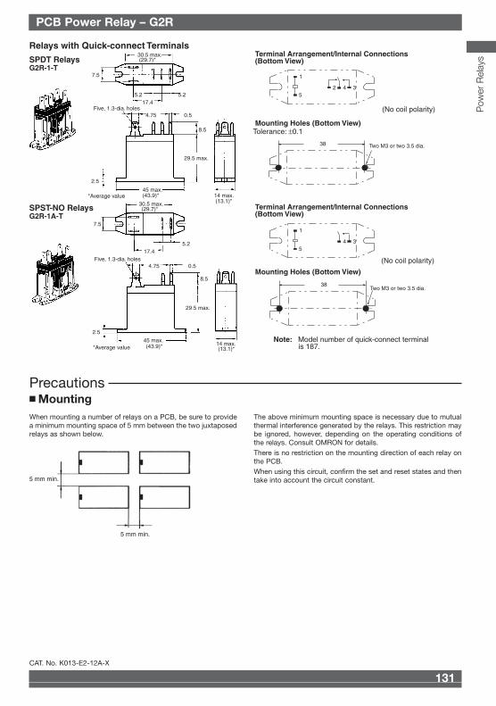
SPDT RelaysG2R-1-T
Relays with Quick-connect Terminals
SPST-NO RelaysG2R-1A-T
Note: Model number of quick-connect terminal is 187.
30.5 max.
7.5
5.2 5.217.4
Five, 1.3-dia. holes4.75 0.5
8.5
29.5 max.
2.5
45 max.14 max.
30.5 max.
7.5
17.45.2
Five, 1.3-dia. holes4.75 0.5
8.5
29.5 max.
2.5
45 max.14 max.
Mounting Holes (Bottom View)Tolerance: ±0.1
38 Two M3 or two 3.5 dia.
Terminal Arrangement/Internal Connections (Bottom View)
Mounting Holes (Bottom View)
Terminal Arrangement/Internal Connections (Bottom View)
38Two M3 or two 3.5 dia.
1
54 32
1
54 3
(No coil polarity)
(No coil polarity)
*Average value
(29.7)*
(13.1)*(43.9)*
(43.9)* (13.1)*
(29.7)*
*Average value
Precautions■ MountingWhen mounting a number of relays on a PCB, be sure to providea minimum mounting space of 5 mm between the two juxtaposedrelays as shown below.
The above minimum mounting space is necessary due to mutualthermal interference generated by the relays. This restriction maybe ignored, however, depending on the operating conditions ofthe relays. Consult OMRON for details.There is no restriction on the mounting direction of each relay onthe PCB.When using this circuit, confirm the set and reset states and thentake into account the circuit constant.5 mm min.
5 mm min.
CAT. No. K013-E2-12A-X
PCB Power Relay – G2R
DPST-NO RelaysG2R-2A4
Double-winding Latching Relays with PCB Terminals
SPDT RelaysG2RK-1
29 max. 13.5 max.
25.5 max.
4 0.3
0.15
0.5 1
29 max. 13 max.
25.5 max.(25.2)*
4
(0.3)
0.31
0.5 1
20
5
7.5
(2.7)
(2.1)(2.1)
Six, 1.3-dia.holes
20
7.5
3.5 3.5
(2.1)
Seven, 1.3-dia.holes
5
(2.7)
1
8
3 4
6 5
1
7
3 4
5
2
6
S R+
-
+
-
*Average value
*Average value
(24.7)*
(28.8)* (12.8)*
(12.8)*(28.6)*
(No coil polarity)
(After confirming coil polarity, wire correctly.)
Double-winding Latching Relays with PCB TerminalsSPST-NO RelaysG2RK-1A
Mounting Holes (Bottom View)
Terminal Arrangement/Internal Connections (Bottom View) Tolerance: ±0.1
DPDT RelaysG2RK-2
DPST-NO RelaysG2RK-2A
29 max. 13 max.
25.5 max.(25.2)*
(0.3)
4 0.3 0.51 0.16
1
29 max. 13 max.
25.5 max.(25.2)*
(0.3)
4 0.3 0.180.18 1
1 0.15
29 max.13 max.
25.5 max.
(0.3)
4 0.3 0.18 1
1 0.15
20
7.5
3.5
(2.1)
(2.7)
Six, 1.3-dia.holes
5
10
5 5
7.5
(2.7)
(2.1)(2.1)
Eight, 1.3-dia.holes5
(2.7)
5
7.5
(2.7)
(2.1)(2.1)
Six, 1.3-dia.holes5
15(2.7)
1
7
4
5
2
6
S R+
-
+
-
1
10
4 53
7 68
2
9S R+
-
+
-
1
10
4 5
7 6
2
9S R+
-
+
-
(After confirming coil polarity, wire correctly.)
(After confirming coil polarity, wire correctly.)
(After confirming coil polarity, wire correctly.)
(28.8)* (12.8)*
(12.8)*(28.8)*
*Average value
*Average value
Pow
er R
elay
s
Omron 08 Cat 1-302 5/10/07 15:39 Page 130


![Standard specifications - Nachi Robotics · Standard specifications MZ07-02 ... [rad] = 180 /π[°], 1[N・m ... - The specification and externals described in this specifications](https://static.fdocument.org/doc/165x107/5b15cdf47f8b9a5e798b477d/standard-specifications-nachi-standard-specifications-mz07-02-rad-.jpg)