Prof. Girish Kumar · (FNBW) y x Major Lobe Side Lobe z. Directivity of Antenna ` Uo U DUmo ......
15
Prof. Girish Kumar Electrical Engineering Department, IIT Bombay [email protected] (022) 2576 7436 Antenna Fundamentals
Transcript of Prof. Girish Kumar · (FNBW) y x Major Lobe Side Lobe z. Directivity of Antenna ` Uo U DUmo ......

Prof. Girish KumarElectrical Engineering Department, IIT Bombay
[email protected](022) 2576 7436
Antenna Fundamentals
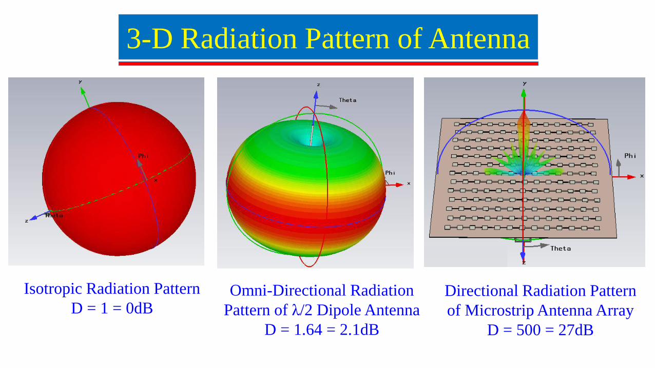
`3-D Radiation Pattern of Antenna
Omni-Directional Radiation Pattern of λ/2 Dipole Antenna
D = 1.64 = 2.1dB
Isotropic Radiation PatternD = 1 = 0dB
Directional Radiation Pattern of Microstrip Antenna Array
D = 500 = 27dB
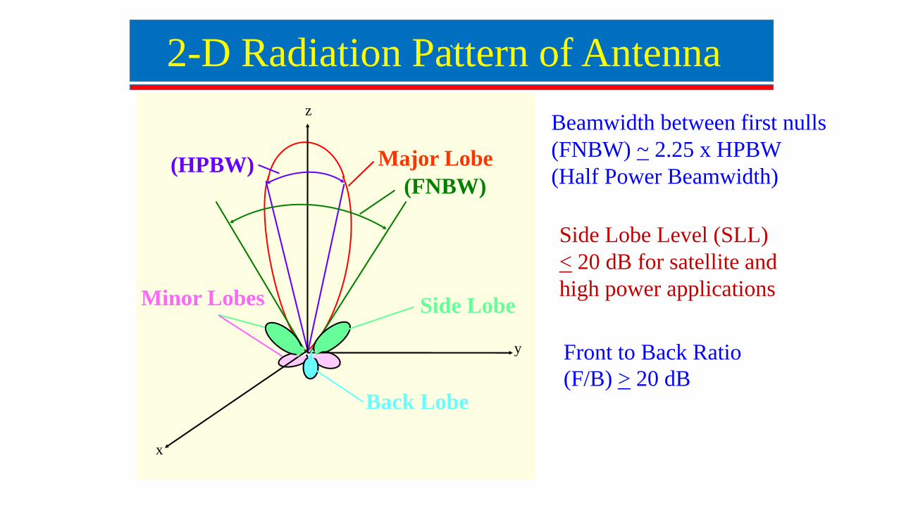
`2-D Radiation Pattern of Antenna
Beamwidth between first nulls (FNBW) ~ 2.25 x HPBW (Half Power Beamwidth)
Side Lobe Level (SLL) < 20 dB for satellite and high power applications
Front to Back Ratio (F/B) > 20 dB
Back Lobe
Minor Lobes
(HPBW)(FNBW)
y
x
Major Lobe
Side Lobe
z
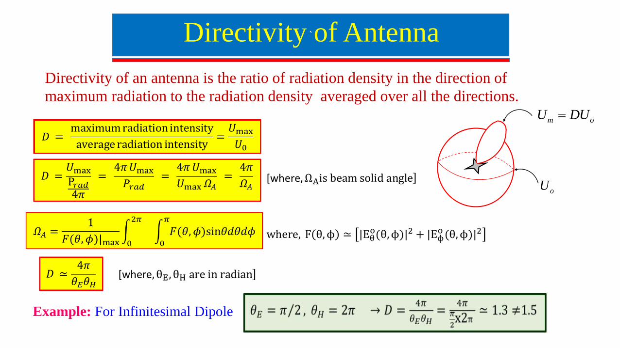
`Directivity of Antenna
oU
m oU DU
Directivity of an antenna is the ratio of radiation density in the direction of maximum radiation to the radiation density averaged over all the directions.
Example: For Infinitesimal Dipole
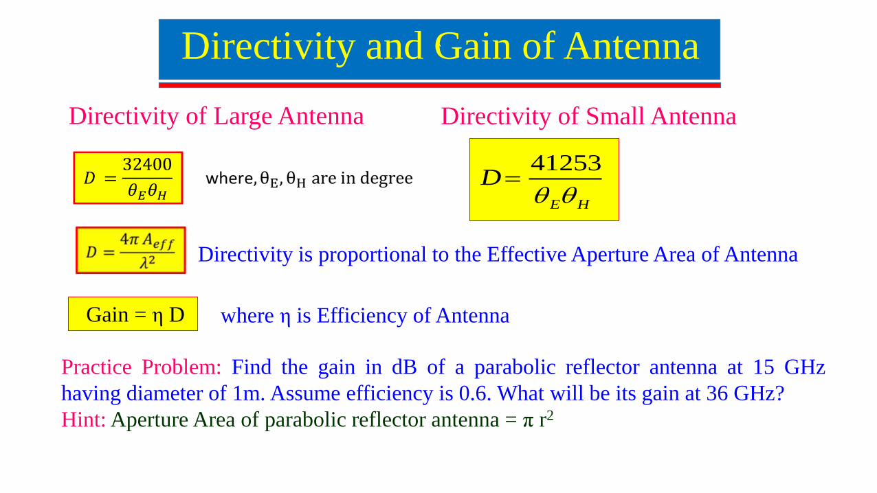
`Directivity and Gain of Antenna
Gain = η D
Directivity of Large Antenna
Practice Problem: Find the gain in dB of a parabolic reflector antenna at 15 GHzhaving diameter of 1m. Assume efficiency is 0.6. What will be its gain at 36 GHz?Hint: Aperture Area of parabolic reflector antenna = π r2
where η is Efficiency of Antenna
Directivity is proportional to the Effective Aperture Area of Antenna
41253
E H
D
Directivity of Small Antenna
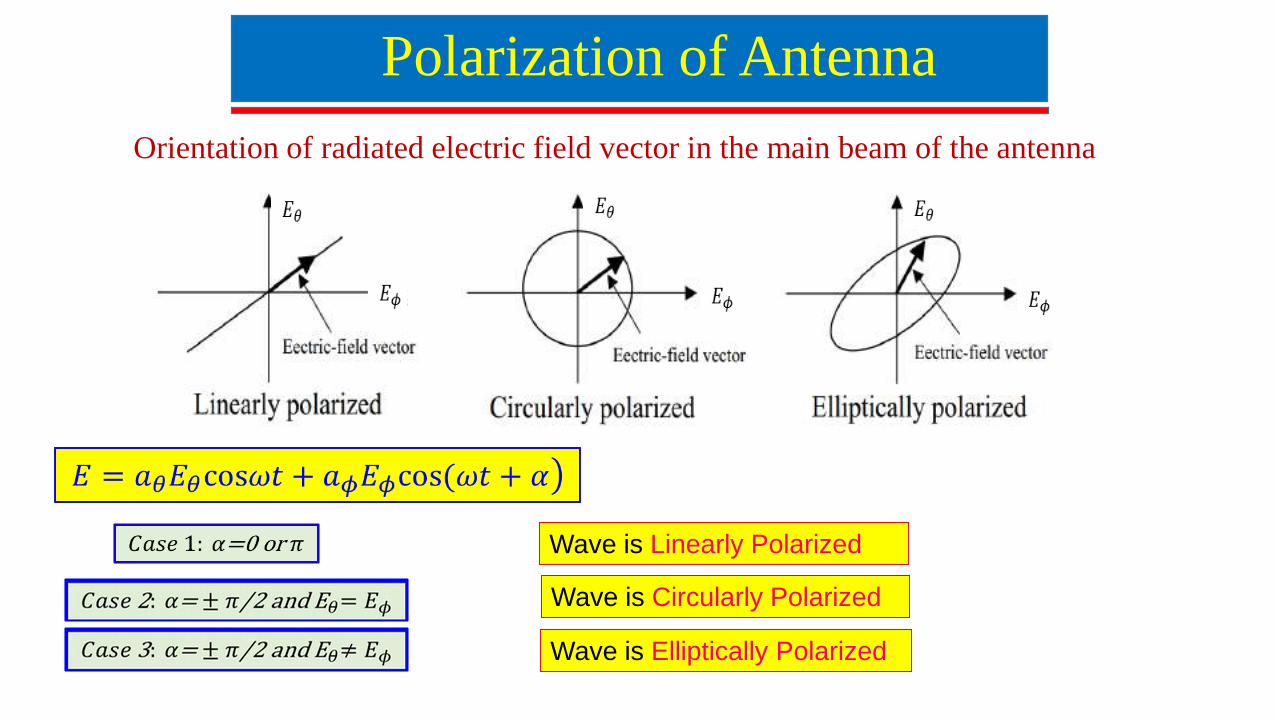
Polarization of Antenna
Orientation of radiated electric field vector in the main beam of the antenna
Wave is Linearly Polarized
Wave is Circularly Polarized
Wave is Elliptically Polarized
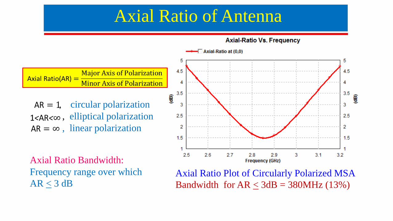
Axial Ratio of Antenna
Axial Ratio Bandwidth: Frequency range over which AR < 3 dB
Axial Ratio Plot of Circularly Polarized MSABandwidth for AR < 3dB = 380MHz (13%)
, circular polarization, elliptical polarization, linear polarization
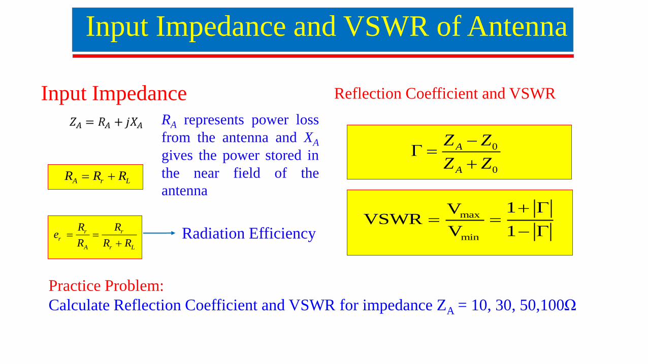
Input Impedance and VSWR of Antenna
Input ImpedanceRA represents power lossfrom the antenna and XA
gives the power stored inthe near field of theantenna
A r LR R R
r rr
A r L
R Re
R R R
Radiation Efficiency
0
0
A
A
Z Z
Z Z
max
min
1VVSWR
V 1
Reflection Coefficient and VSWR
Practice Problem: Calculate Reflection Coefficient and VSWR for impedance ZA = 10, 30, 50,100Ω
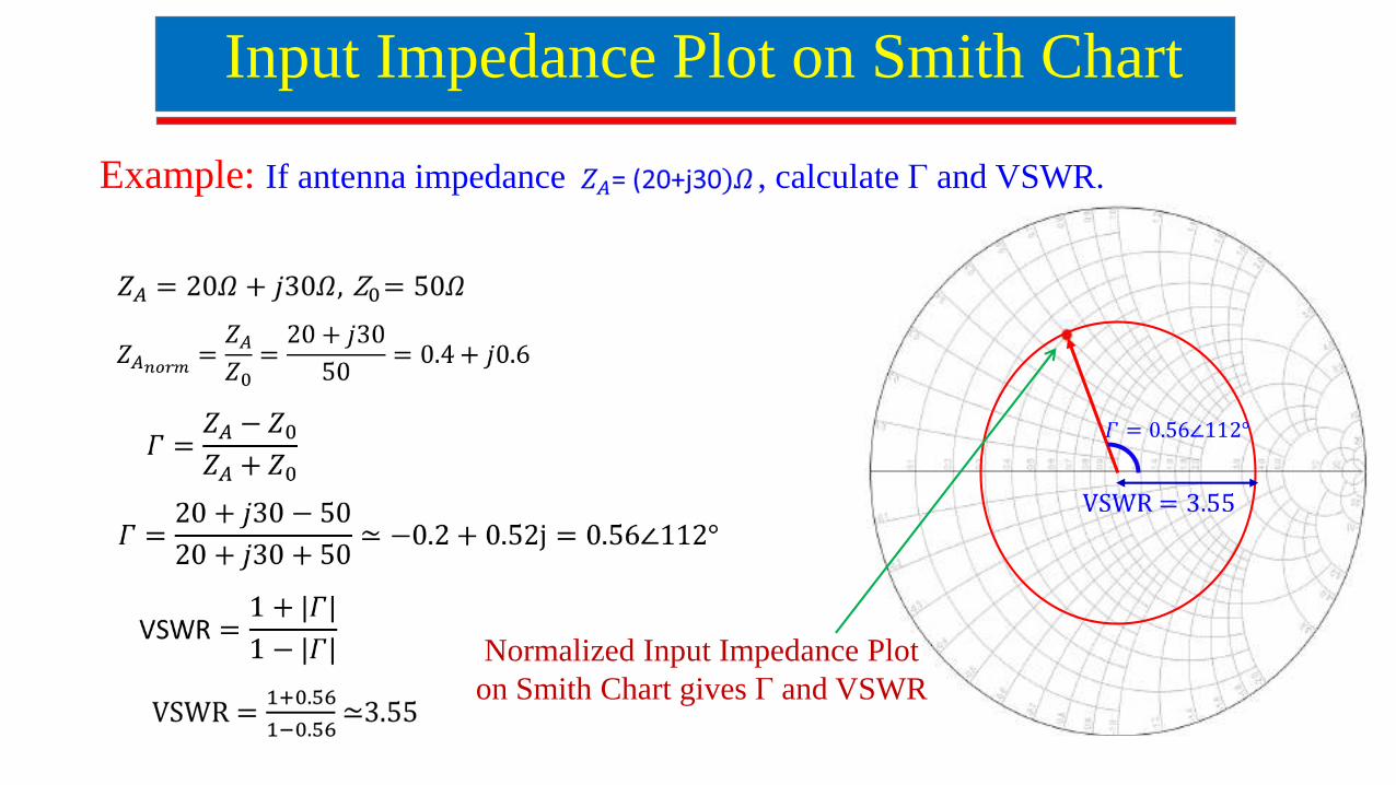
Example: If antenna impedance , calculate Γ and VSWR.
Input Impedance Plot on Smith Chart
Normalized Input Impedance Plot on Smith Chart gives Γ and VSWR
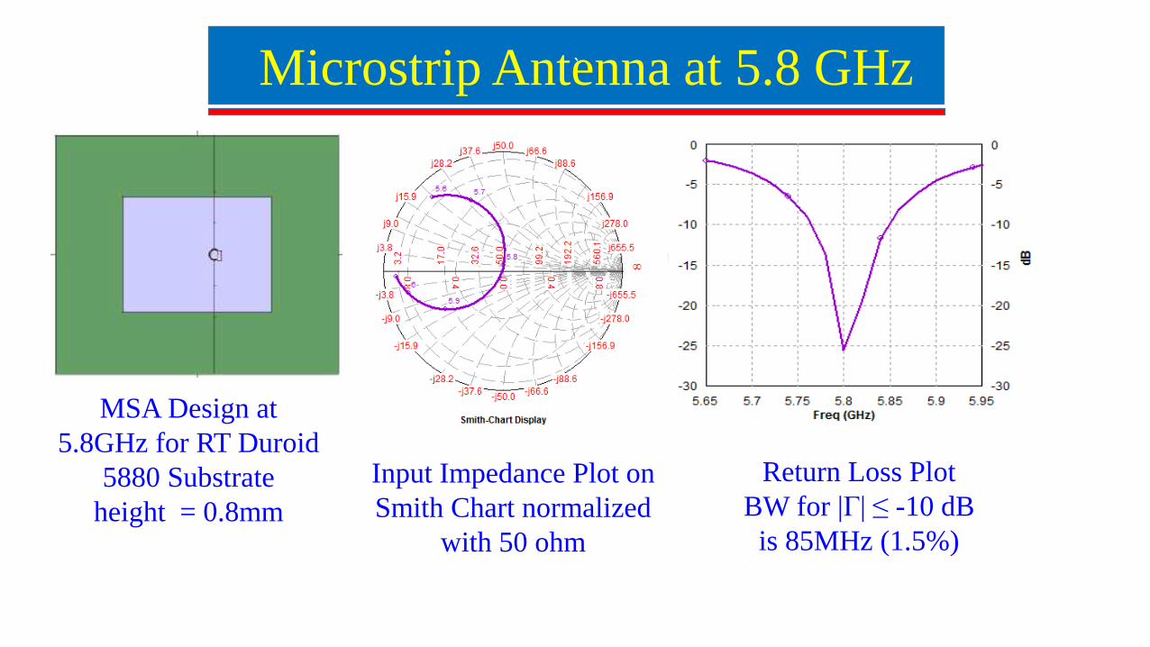
`Microstrip Antenna at 5.8 GHz
Return Loss Plot BW for |Γ| ≤ -10 dB
is 85MHz (1.5%)
Input Impedance Plot on Smith Chart normalized
with 50 ohm
MSA Design at 5.8GHz for RT Duroid
5880 Substrate height = 0.8mm
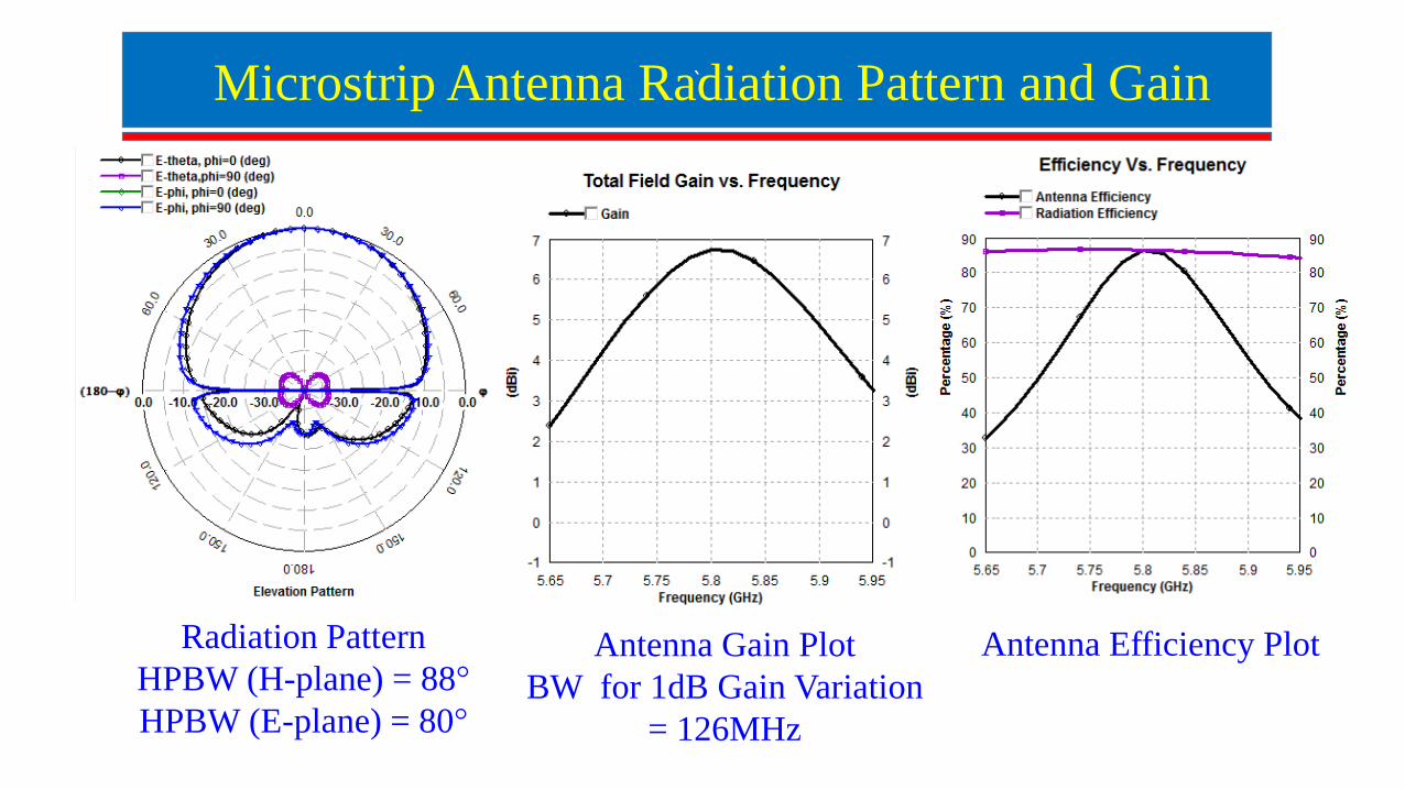
`Microstrip Antenna Radiation Pattern and Gain
Antenna Gain PlotBW for 1dB Gain Variation
= 126MHz
Radiation PatternHPBW (H-plane) = 88°
HPBW (E-plane) = 80°
Antenna Efficiency Plot
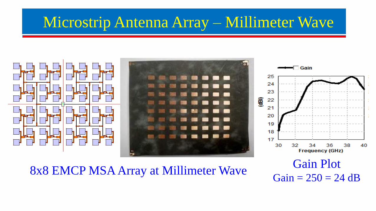
`Microstrip Antenna Array – Millimeter Wave
8x8 EMCP MSA Array at Millimeter Wave Gain PlotGain = 250 = 24 dB
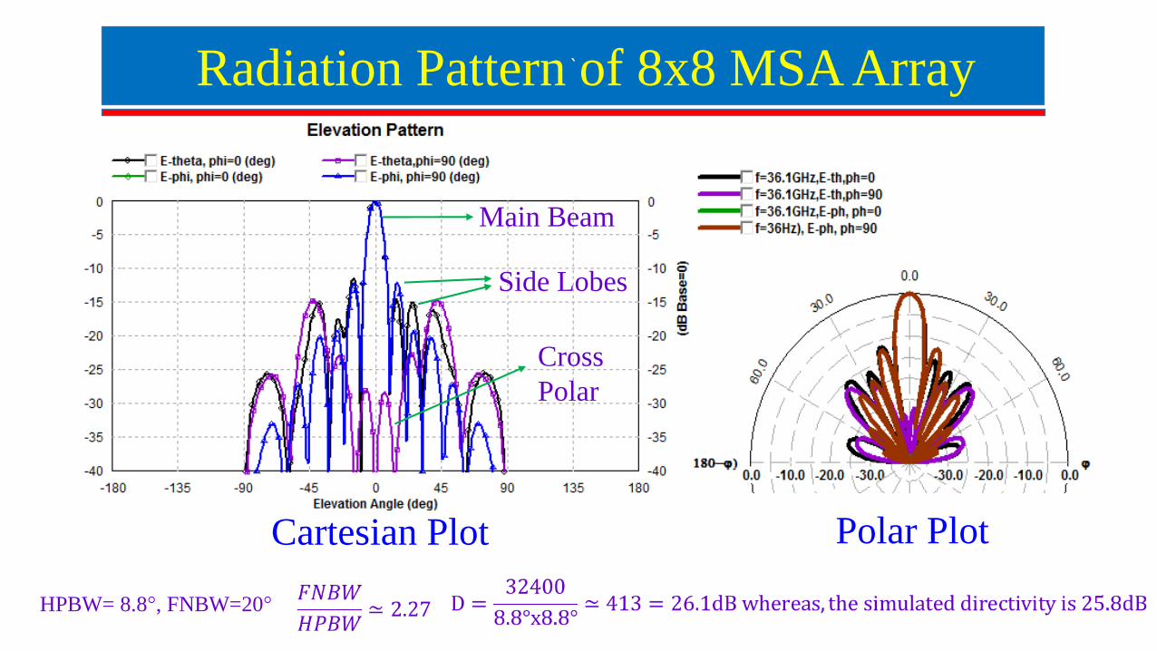
`Radiation Pattern of 8x8 MSA Array
Side Lobes
Main Beam
Cross Polar
Cartesian Plot Polar Plot
HPBW= 8.8°, FNBW=20°
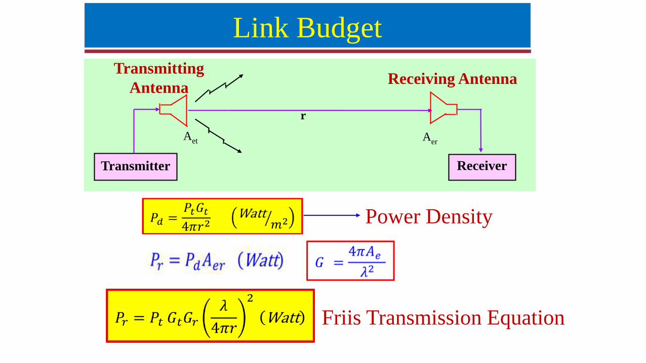
Link Budget
Receiving AntennaTransmitting
Antenna
r
Transmitter Receiver
Aet Aer
Friis Transmission Equation
Power Density
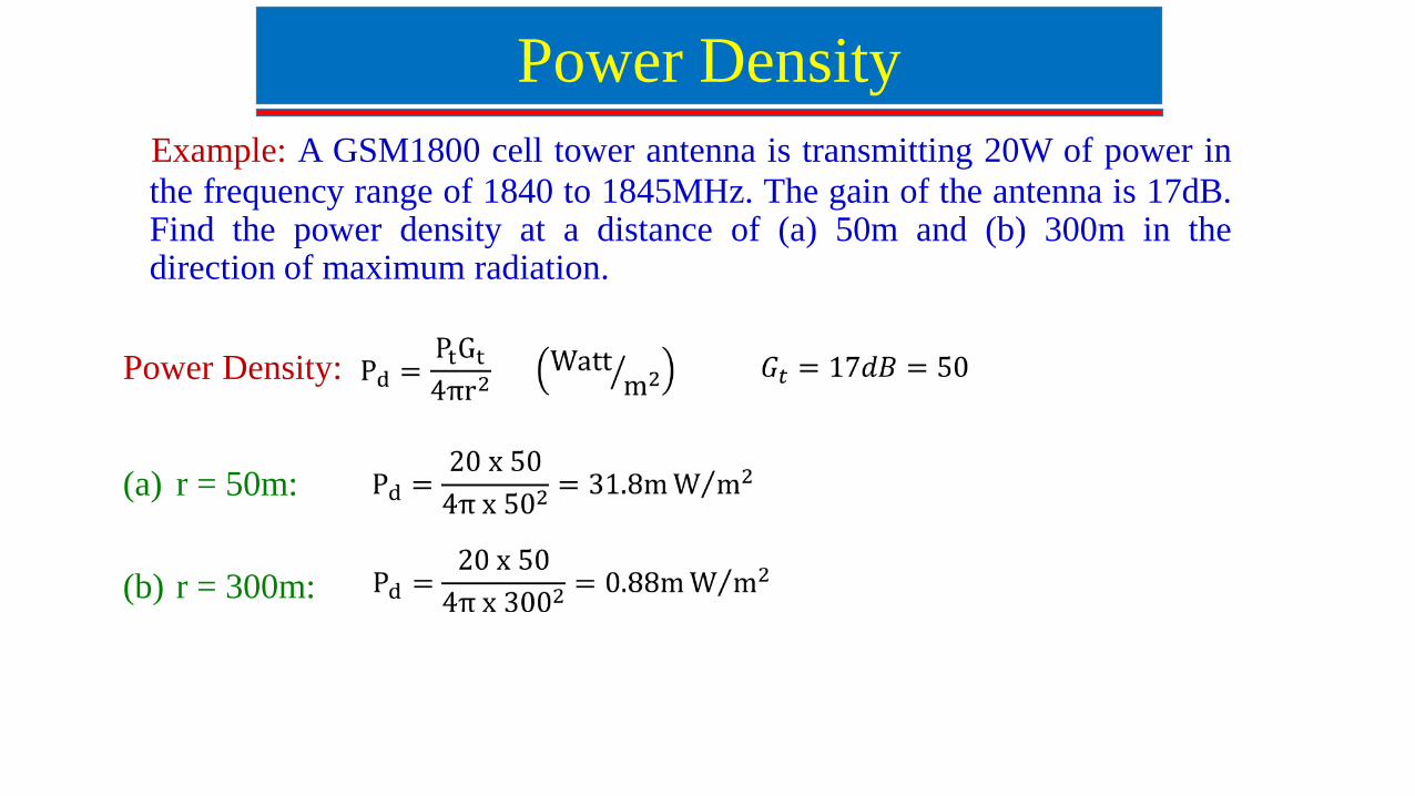
Example: A GSM1800 cell tower antenna is transmitting 20W of power inthe frequency range of 1840 to 1845MHz. The gain of the antenna is 17dB.Find the power density at a distance of (a) 50m and (b) 300m in thedirection of maximum radiation.
Power Density:
(a) r = 50m:
(b) r = 300m:
Power Density