Hybrid Simulation for Electrically Large Antenna Platforms
41
CST – COMPUTER SIMULATION TECHNOLOGY | www.cst.com Hybrid Simulation for Electrically Large Antenna Platforms Jim Creed 2016-04-12
Transcript of Hybrid Simulation for Electrically Large Antenna Platforms

CST – COMPUTER SIMULATION TECHNOLOGY | www.cst.com CST – COMPUTER SIMULATION TECHNOLOGY | www.cst.com
Hybrid Simulation for Electrically Large Antenna Platforms Jim Creed 2016-04-12
CST – COMPUTER SIMULATION TECHNOLOGY | www.cst.com
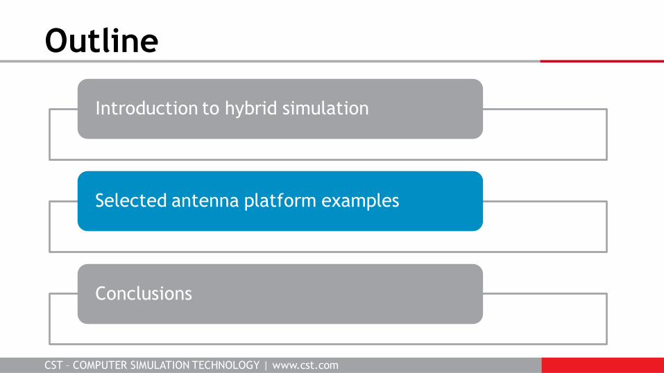
Outline
Introduction to hybrid simulation
Selected antenna platform examples
Conclusions
CST – COMPUTER SIMULATION TECHNOLOGY | www.cst.com
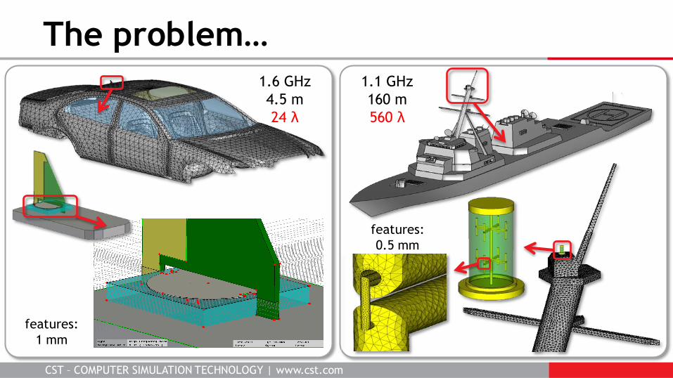
The problem…
1.6 GHz
4.5 m
24 λ
1.1 GHz
160 m
560 λ
features:
1 mm
features:
0.5 mm
CST – COMPUTER SIMULATION TECHNOLOGY | www.cst.com
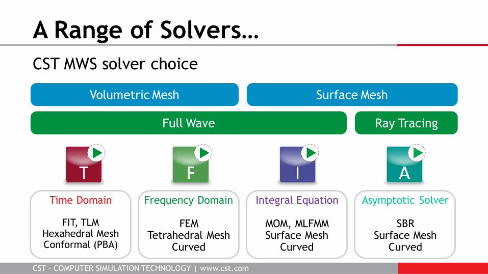
CST MWS solver choice
A Range of Solvers…
Ray Tracing
Volumetric Mesh Surface Mesh
Full Wave
Time Domain
FIT, TLM Hexahedral Mesh Conformal (PBA)
Frequency Domain
FEM Tetrahedral Mesh
Curved
Integral Equation
MOM, MLFMM Surface Mesh
Curved
Asymptotic Solver
SBR Surface Mesh
Curved
CST – COMPUTER SIMULATION TECHNOLOGY | www.cst.com
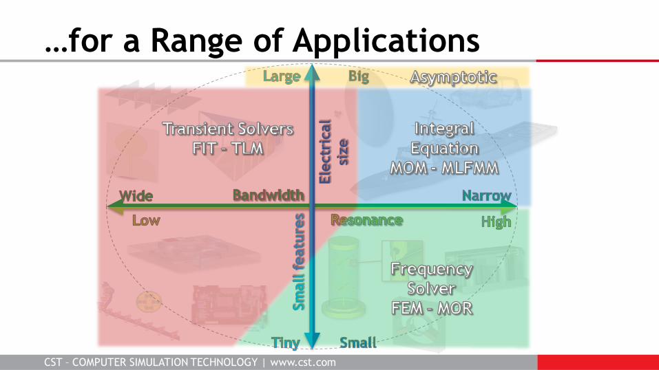
…for a Range of Applications
CST – COMPUTER SIMULATION TECHNOLOGY | www.cst.com
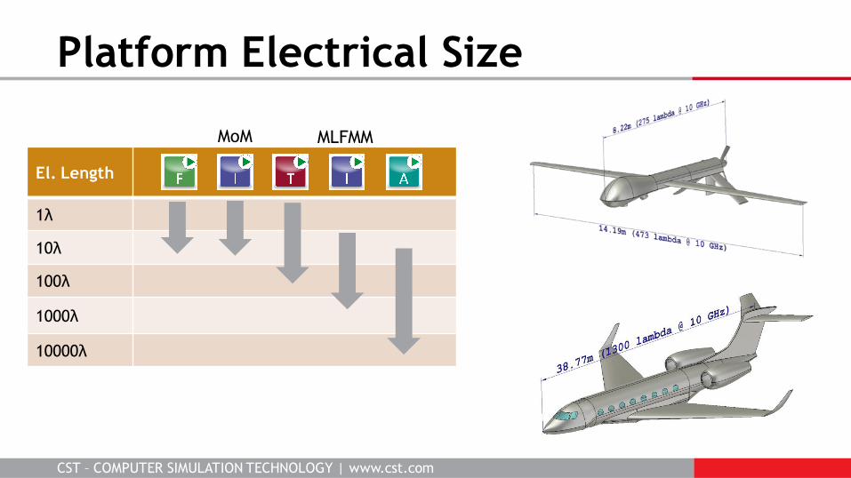
Platform Electrical Size
El. Length
1λ
10λ
100λ
1000λ
10000λ
MoM MLFMM
CST – COMPUTER SIMULATION TECHNOLOGY | www.cst.com
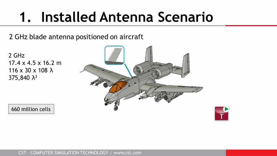
1. Installed Antenna Scenario
2 GHz
17.4 x 4.5 x 16.2 m
116 x 30 x 108 λ
375,840 λ3
2 GHz blade antenna positioned on aircraft
660 million cells
CST – COMPUTER SIMULATION TECHNOLOGY | www.cst.com
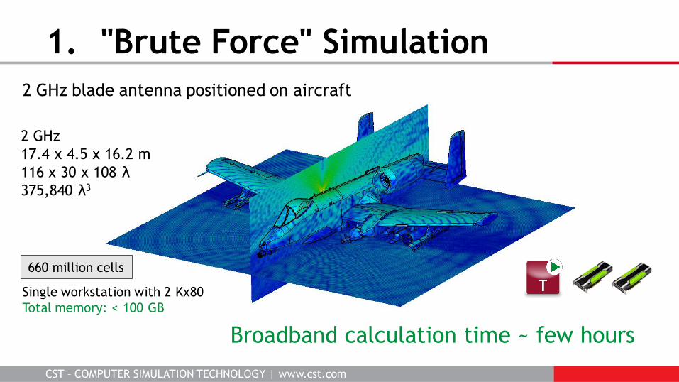
1. "Brute Force" Simulation
Single workstation with 2 Kx80
Total memory: < 100 GB
Broadband calculation time ~ few hours
660 million cells
2 GHz blade antenna positioned on aircraft
2 GHz
17.4 x 4.5 x 16.2 m
116 x 30 x 108 λ
375,840 λ3
CST – COMPUTER SIMULATION TECHNOLOGY | www.cst.com
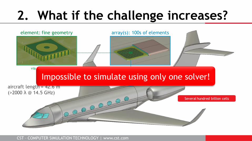
2. What if the challenge increases?
aircraft length = 42.6 m
(>2000 λ @ 14.5 GHz)
array(s): 100s of elements element: fine geometry
via radius = 0.4 mm
Several hundred billion cells
Impossible to simulate using only one solver!
CST – COMPUTER SIMULATION TECHNOLOGY | www.cst.com
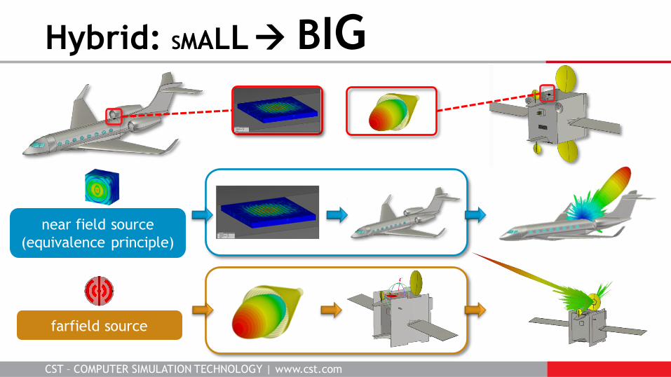
Hybrid: SMALL BIG
near field source
(equivalence principle)
farfield source
CST – COMPUTER SIMULATION TECHNOLOGY | www.cst.com
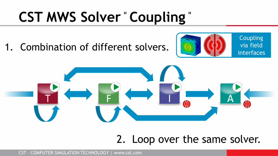
CST MWS Solver ̎ Coupling ̎
1. Combination of different solvers. Coupling
via field
interfaces
2. Loop over the same solver.
CST – COMPUTER SIMULATION TECHNOLOGY | www.cst.com
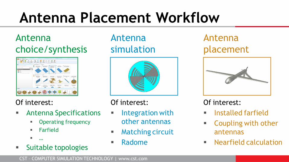
Antenna
choice/synthesis
Of interest:
Antenna Specifications Operating frequency
Farfield
…
Suitable topologies
Antenna
placement
Of interest:
Installed farfield
Coupling with other
antennas
Nearfield calculation
Antenna Placement Workflow
Antenna
simulation
Of interest:
Integration with
other antennas
Matching circuit
Radome
CST – COMPUTER SIMULATION TECHNOLOGY | www.cst.com
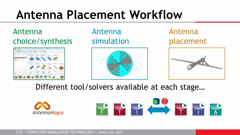
Antenna
choice/synthesis
Antenna
placement
Antenna Placement Workflow
Antenna
simulation
Different tool/solvers available at each stage…
CST – COMPUTER SIMULATION TECHNOLOGY | www.cst.com
Outline
Introduction to hybrid simulation
Selected antenna platform examples
Conclusions
CST – COMPUTER SIMULATION TECHNOLOGY | www.cst.com
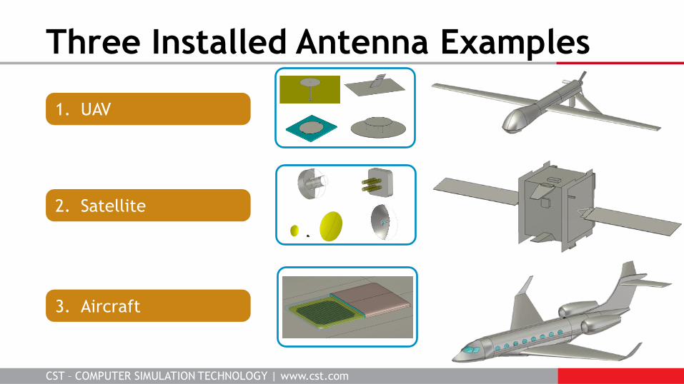
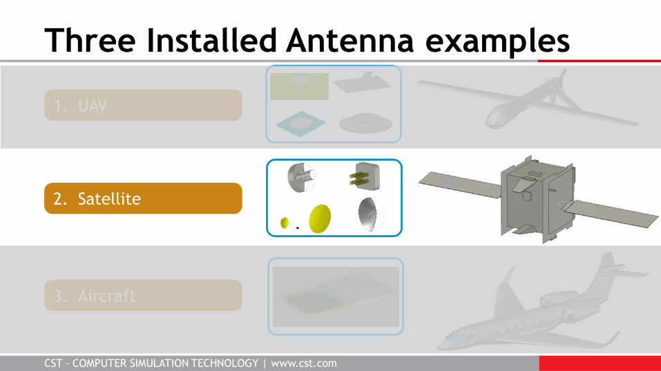
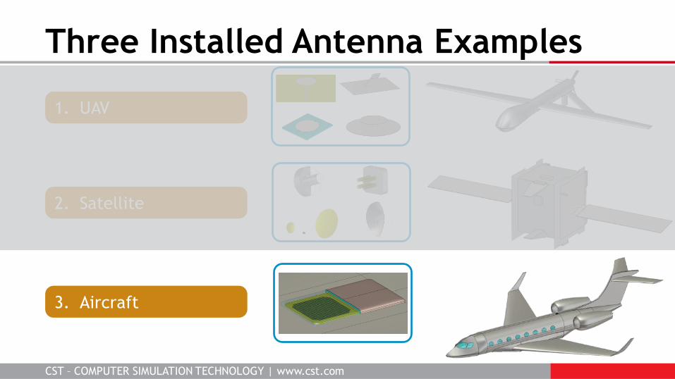
Three Installed Antenna Examples
1. UAV
2. Satellite
3. Aircraft
CST – COMPUTER SIMULATION TECHNOLOGY | www.cst.com
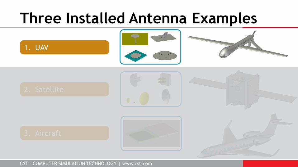
Three Installed Antenna Examples
1. UAV
2. Satellite
3. Aircraft
CST – COMPUTER SIMULATION TECHNOLOGY | www.cst.com
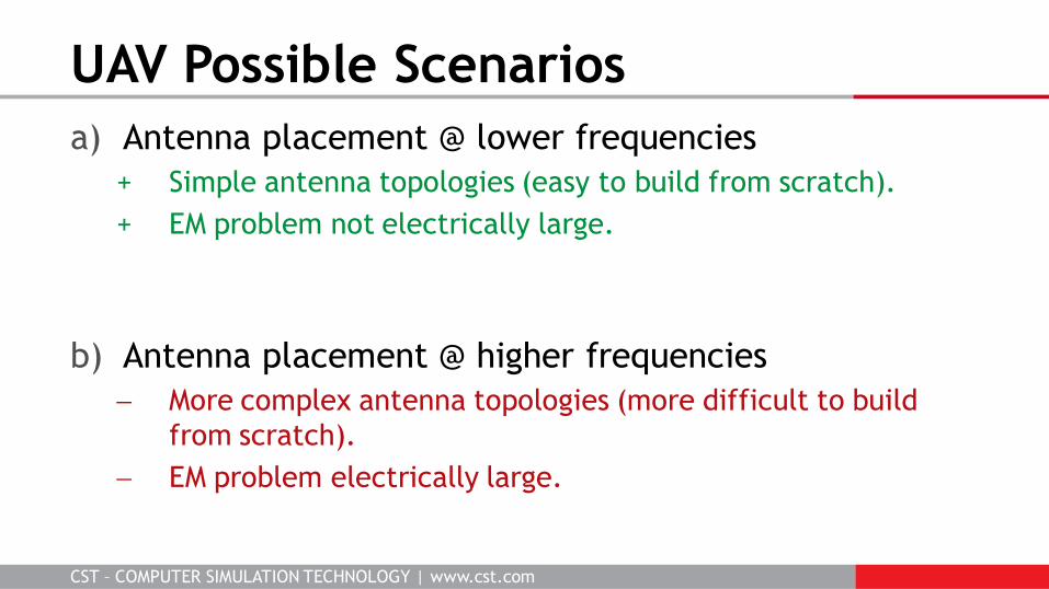
a) Antenna placement @ lower frequencies
+ Simple antenna topologies (easy to build from scratch).
+ EM problem not electrically large.
b) Antenna placement @ higher frequencies
More complex antenna topologies (more difficult to build
from scratch).
EM problem electrically large.
UAV Possible Scenarios
CST – COMPUTER SIMULATION TECHNOLOGY | www.cst.com
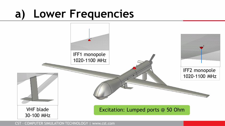
a) Lower Frequencies
VHF blade
30-100 MHz
IFF1 monopole
1020-1100 MHz
IFF2 monopole
1020-1100 MHz
Excitation: Lumped ports @ 50 Ohm
CST – COMPUTER SIMULATION TECHNOLOGY | www.cst.com
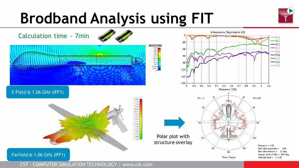
Brodband Analysis using FIT Calculation time ~ 7min
E-Field @ 1.06 GHz (IFF1)
Farfield @ 1.06 GHz (IFF1)
Polar plot with
structure overlay
CST – COMPUTER SIMULATION TECHNOLOGY | www.cst.com
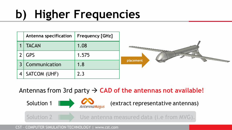
Solution 1 (extract representative antennas)
Solution 2 Use antenna measured data (i.e from MVG).
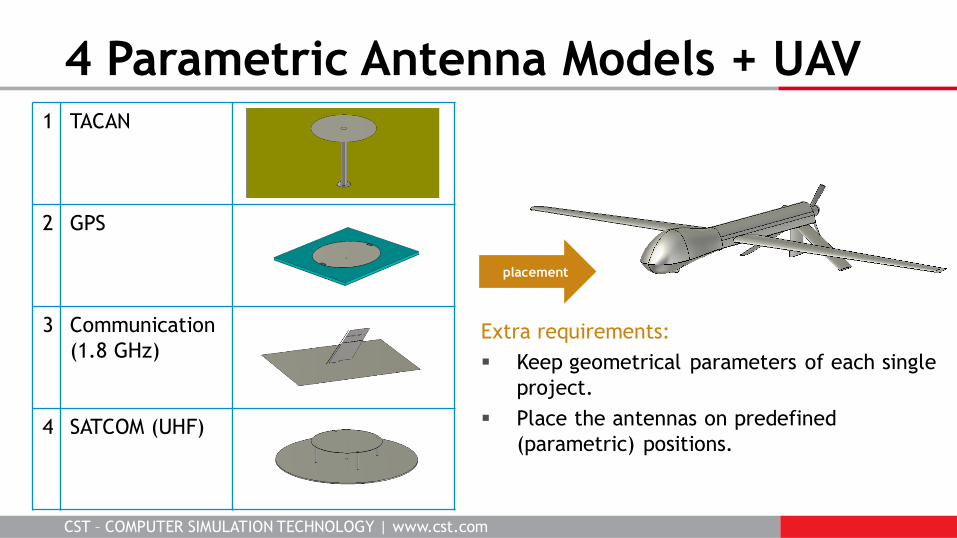
b) Higher Frequencies
Antenna specification Frequency [GHz]
1 TACAN 1.08
2 GPS 1.575
3 Communication 1.8
4 SATCOM (UHF) 2.3
Antennas from 3rd party CAD of the antennas not available!
placement
CST – COMPUTER SIMULATION TECHNOLOGY | www.cst.com
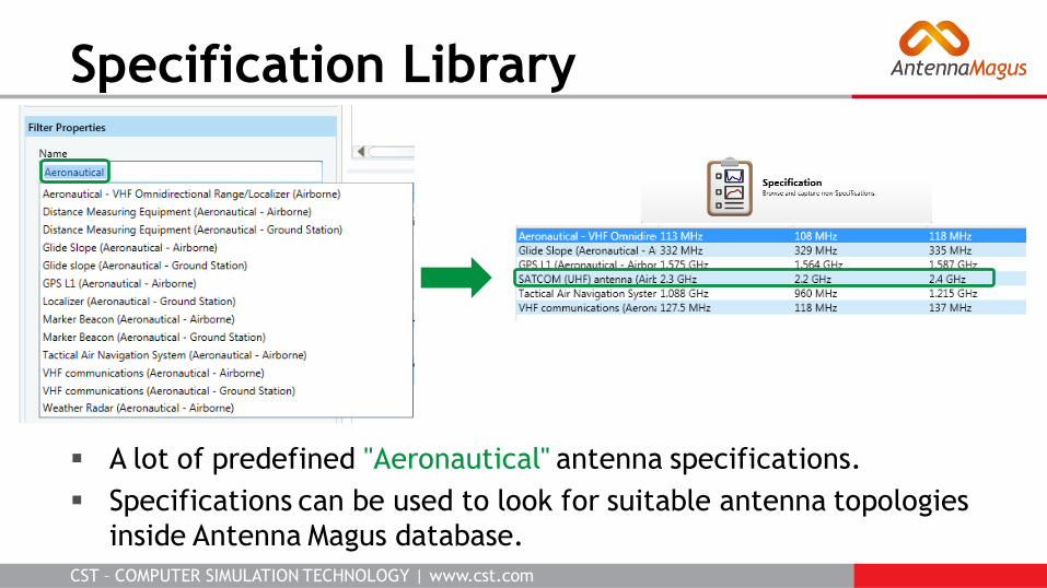
A lot of predefined "Aeronautical" antenna specifications.
Specifications can be used to look for suitable antenna topologies
inside Antenna Magus database.
Specification Library
CST – COMPUTER SIMULATION TECHNOLOGY | www.cst.com
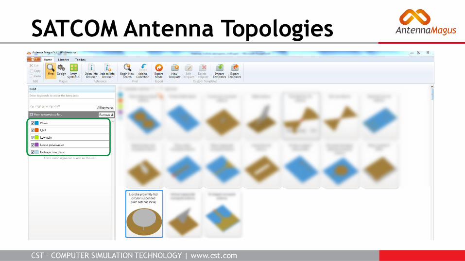
SATCOM Antenna Topologies
CST – COMPUTER SIMULATION TECHNOLOGY | www.cst.com
4 Parametric Antenna Models + UAV 1 TACAN
2 GPS
3 Communication
(1.8 GHz)
4 SATCOM (UHF)
placement
Extra requirements:
Keep geometrical parameters of each single
project.
Place the antennas on predefined
(parametric) positions.
CST – COMPUTER SIMULATION TECHNOLOGY | www.cst.com
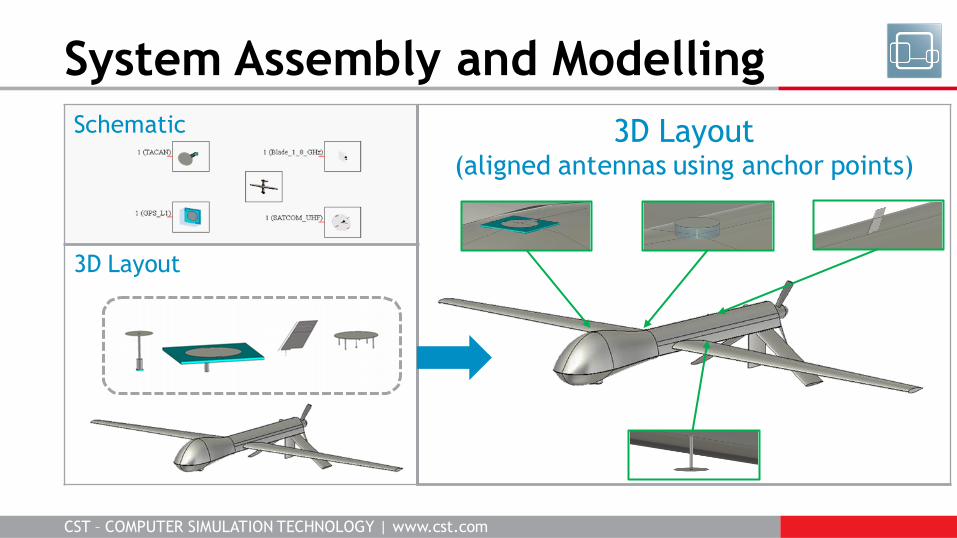
Schematic
3D Layout
System Assembly and Modelling
3D Layout (aligned antennas using anchor points)
CST – COMPUTER SIMULATION TECHNOLOGY | www.cst.com
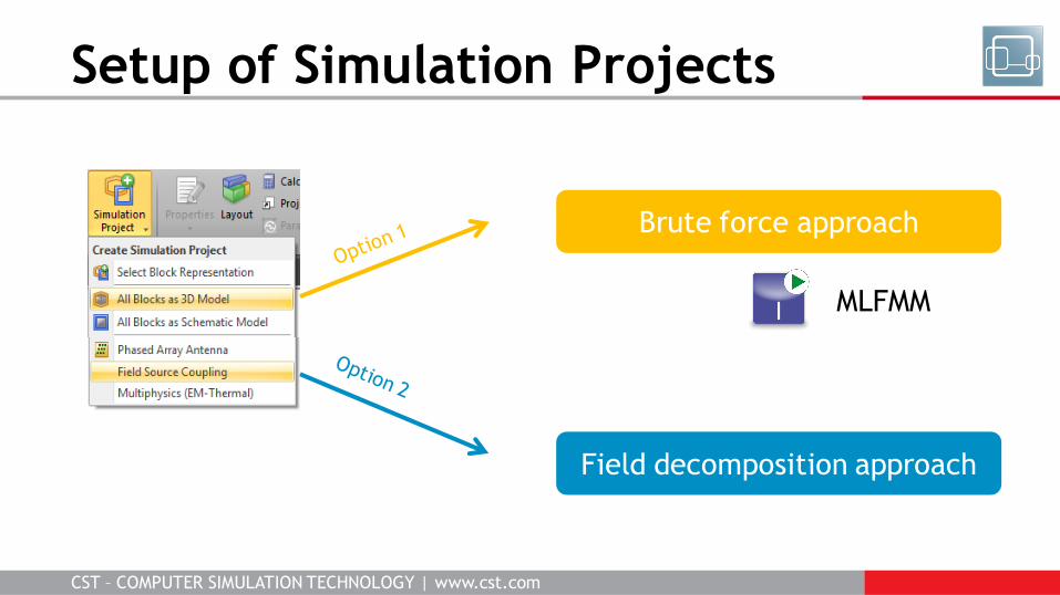
Setup of Simulation Projects
Brute force approach
Field decomposition approach
MLFMM
CST – COMPUTER SIMULATION TECHNOLOGY | www.cst.com
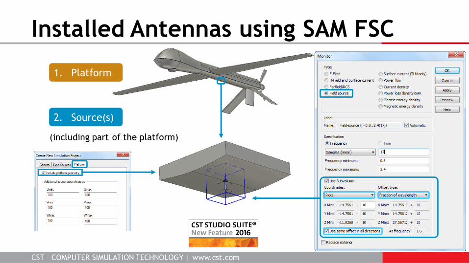
Installed Antennas using SAM FSC
2. Source(s)
1. Platform
(including part of the platform)
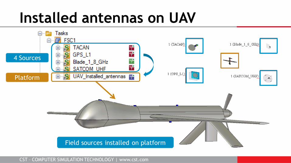
CST – COMPUTER SIMULATION TECHNOLOGY | www.cst.com
Installed antennas on UAV
4 Sources
Platform
Field sources installed on platform
CST – COMPUTER SIMULATION TECHNOLOGY | www.cst.com
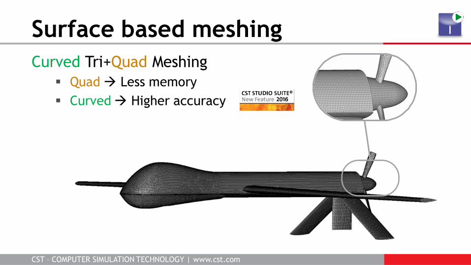
Curved Tri+Quad Meshing
Quad Less memory
Curved Higher accuracy
Surface based meshing
CST – COMPUTER SIMULATION TECHNOLOGY | www.cst.com
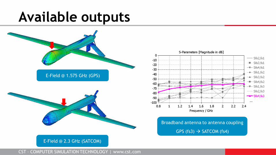
Available outputs
Broadband antenna to antenna coupling
GPS (fs3) SATCOM (fs4)
E-Field @ 2.3 GHz (SATCOM)
E-Field @ 1.575 GHz (GPS)
CST – COMPUTER SIMULATION TECHNOLOGY | www.cst.com
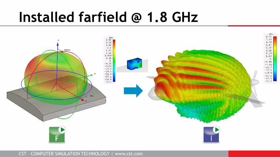
Installed farfield @ 1.8 GHz
CST – COMPUTER SIMULATION TECHNOLOGY | www.cst.com
Three Installed Antenna examples
1. UAV
2. Satellite
3. Aircraft
CST – COMPUTER SIMULATION TECHNOLOGY | www.cst.com
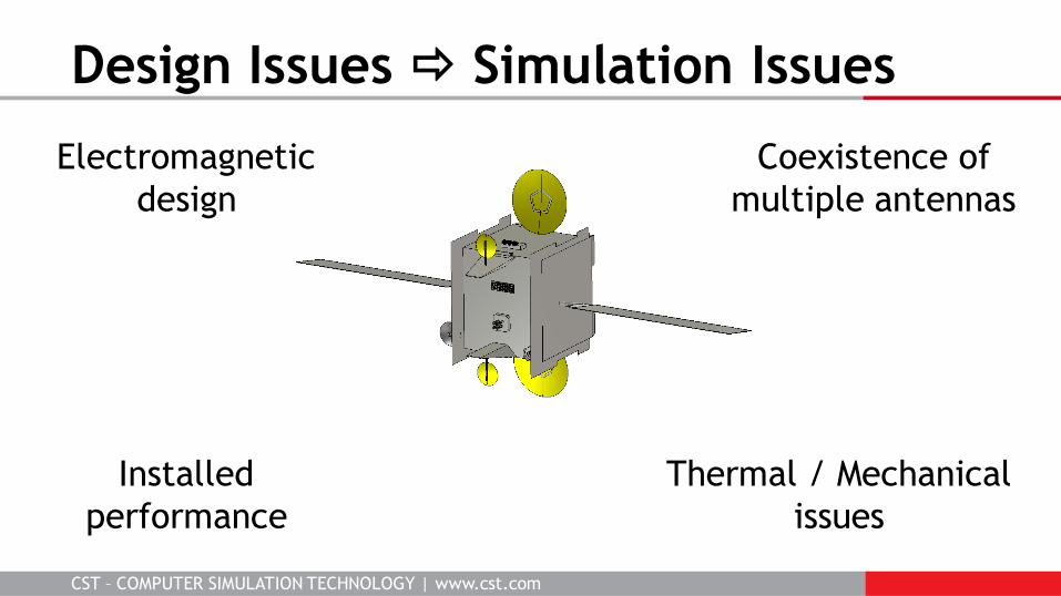
Design Issues Simulation Issues
source: NASA
Coexistence of
multiple antennas
Thermal / Mechanical
issues
Electromagnetic
design
Installed
performance
CST – COMPUTER SIMULATION TECHNOLOGY | www.cst.com
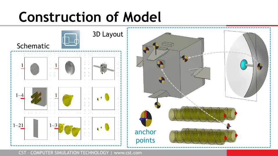
Construction of Model
anchor
points
Schematic
3D Layout
CST – COMPUTER SIMULATION TECHNOLOGY | www.cst.com
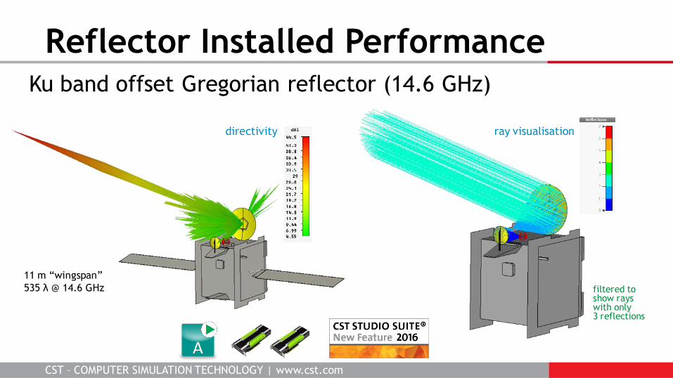
Ku band offset Gregorian reflector (14.6 GHz)
Reflector Installed Performance
filtered to show rays with only 3 reflections
ray visualisation directivity
11 m “wingspan”
535 λ @ 14.6 GHz
CST – COMPUTER SIMULATION TECHNOLOGY | www.cst.com
Three Installed Antenna Examples
1. UAV
2. Satellite
3. Aircraft
CST – COMPUTER SIMULATION TECHNOLOGY | www.cst.com
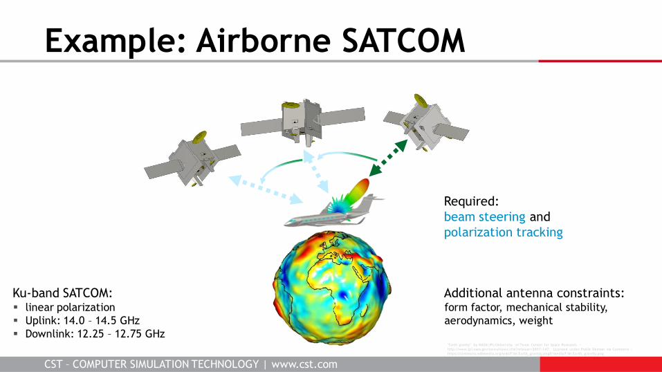
Example: Airborne SATCOM
"Earth gravity" by NASA/JPL/University of Texas Center for Space Research. -
http://www.jpl.nasa.gov/news/news.cfm?release=2007-147. Licensed under Public Domain via Commons -
https://commons.wikimedia.org/wiki/F ile:Earth_gravity.png#/media/F ile:Earth_gravity.png
Ku-band SATCOM: linear polarization
Uplink: 14.0 – 14.5 GHz
Downlink: 12.25 – 12.75 GHz
Additional antenna constraints: form factor, mechanical stability,
aerodynamics, weight
Required:
beam steering and
polarization tracking
CST – COMPUTER SIMULATION TECHNOLOGY | www.cst.com
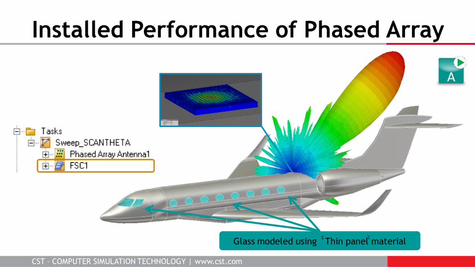
Installed Performance of Phased Array
Glass modeled using ̎̎ Thin panel ̎̎ material
CST – COMPUTER SIMULATION TECHNOLOGY | www.cst.com
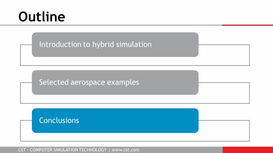
Outline
Introduction to hybrid simulation
Selected aerospace examples
Conclusions
CST – COMPUTER SIMULATION TECHNOLOGY | www.cst.com
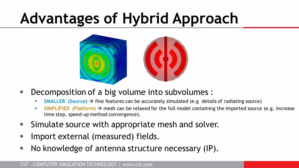
Decomposition of a big volume into subvolumes : SMALLER (Source) fine features can be accurately simulated (e.g details of radiating source)
SIMPLIFIED (Platform) mesh can be relaxed for the full model containing the imported source (e.g. increase
time step, speed-up method convergence).
Simulate source with appropriate mesh and solver.
Import external (measured) fields.
No knowledge of antenna structure necessary (IP).
Advantages of Hybrid Approach
CST – COMPUTER SIMULATION TECHNOLOGY | www.cst.com
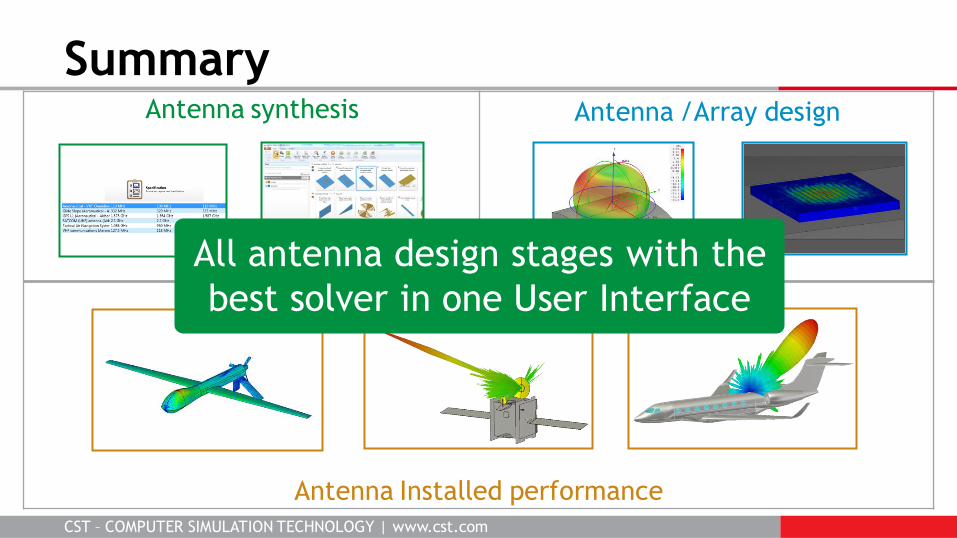
Antenna synthesis
Summary Antenna /Array design
Antenna Installed performance
All antenna design stages with the
best solver in one User Interface
CST – COMPUTER SIMULATION TECHNOLOGY | www.cst.com CST – COMPUTER SIMULATION TECHNOLOGY | www.cst.com
Hybrid Simulation for Electrically Large Antenna Platforms Jim Creed 2016-04-12
Thank you for your time!
We’d be happy to answer any questions.