Chapter 3: Cells Part I: Differentiated Cells, Composite Cells, Cell Membrane.
964 NATURE MATERIALS | VOL 14 | OCTOBER 2015 | www.nature.com/naturematerials
news & views
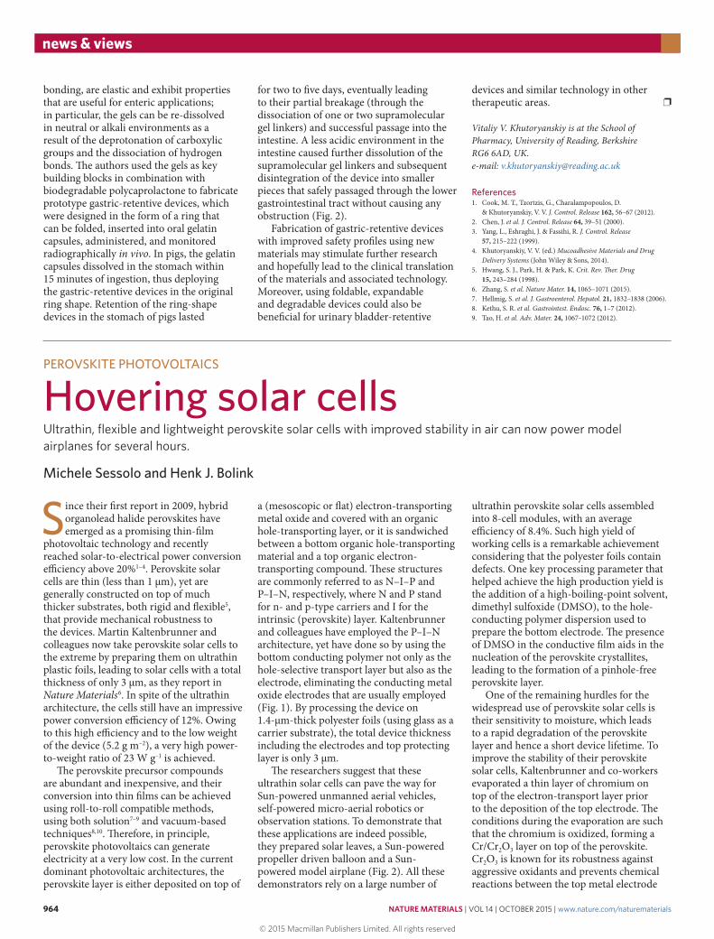
bonding, are elastic and exhibit properties that are useful for enteric applications; in particular, the gels can be re-dissolved in neutral or alkali environments as a result of the deprotonation of carboxylic groups and the dissociation of hydrogen bonds. The authors used the gels as key building blocks in combination with biodegradable polycaprolactone to fabricate prototype gastric-retentive devices, which were designed in the form of a ring that can be folded, inserted into oral gelatin capsules, administered, and monitored radiographically in vivo. In pigs, the gelatin capsules dissolved in the stomach within 15 minutes of ingestion, thus deploying the gastric-retentive devices in the original ring shape. Retention of the ring-shape devices in the stomach of pigs lasted
for two to five days, eventually leading to their partial breakage (through the dissociation of one or two supramolecular gel linkers) and successful passage into the intestine. A less acidic environment in the intestine caused further dissolution of the supramolecular gel linkers and subsequent disintegration of the device into smaller pieces that safely passaged through the lower gastrointestinal tract without causing any obstruction (Fig. 2).
Fabrication of gastric-retentive devices with improved safety profiles using new materials may stimulate further research and hopefully lead to the clinical translation of the materials and associated technology. Moreover, using foldable, expandable and degradable devices could also be beneficial for urinary bladder-retentive
devices and similar technology in other therapeutic areas. ❐
Vitaliy V. Khutoryanskiy is at the School of Pharmacy, University of Reading, Berkshire RG6 6AD, UK. e-mail: [email protected]
References1. Cook, M. T., Tzortzis, G., Charalampopoulos, D.
& Khutoryanskiy, V. V. J. Control. Release 162, 56–67 (2012).2. Chen, J. et al. J. Control. Release 64, 39–51 (2000).3. Yang, L., Eshraghi, J. & Fassihi, R. J. Control. Release
57, 215–222 (1999).4. Khutoryanskiy, V. V. (ed.) Mucoadhesive Materials and Drug
Delivery Systems (John Wiley & Sons, 2014).5. Hwang, S. J., Park, H. & Park, K. Crit. Rev. Ther. Drug
15, 243–284 (1998).6. Zhang, S. et al. Nature Mater. 14, 1065–1071 (2015).7. Hellmig, S. et al. J. Gastroenterol. Hepatol. 21, 1832–1838 (2006).8. Kethu, S. R. et al. Gastrointest. Endosc. 76, 1–7 (2012).9. Tao, H. et al. Adv. Mater. 24, 1067–1072 (2012).
PEROVSKITE PHOTOVOLTAICS
Hovering solar cellsUltrathin, flexible and lightweight perovskite solar cells with improved stability in air can now power model airplanes for several hours.
Michele Sessolo and Henk J. Bolink
Since their first report in 2009, hybrid organolead halide perovskites have emerged as a promising thin-film
photovoltaic technology and recently reached solar-to-electrical power conversion efficiency above 20%1–4. Perovskite solar cells are thin (less than 1 μm), yet are generally constructed on top of much thicker substrates, both rigid and flexible5, that provide mechanical robustness to the devices. Martin Kaltenbrunner and colleagues now take perovskite solar cells to the extreme by preparing them on ultrathin plastic foils, leading to solar cells with a total thickness of only 3 μm, as they report in Nature Materials6. In spite of the ultrathin architecture, the cells still have an impressive power conversion efficiency of 12%. Owing to this high efficiency and to the low weight of the device (5.2 g m–2), a very high power-to-weight ratio of 23 W g–1 is achieved.
The perovskite precursor compounds are abundant and inexpensive, and their conversion into thin films can be achieved using roll-to-roll compatible methods, using both solution7–9 and vacuum-based techniques8,10. Therefore, in principle, perovskite photovoltaics can generate electricity at a very low cost. In the current dominant photovoltaic architectures, the perovskite layer is either deposited on top of
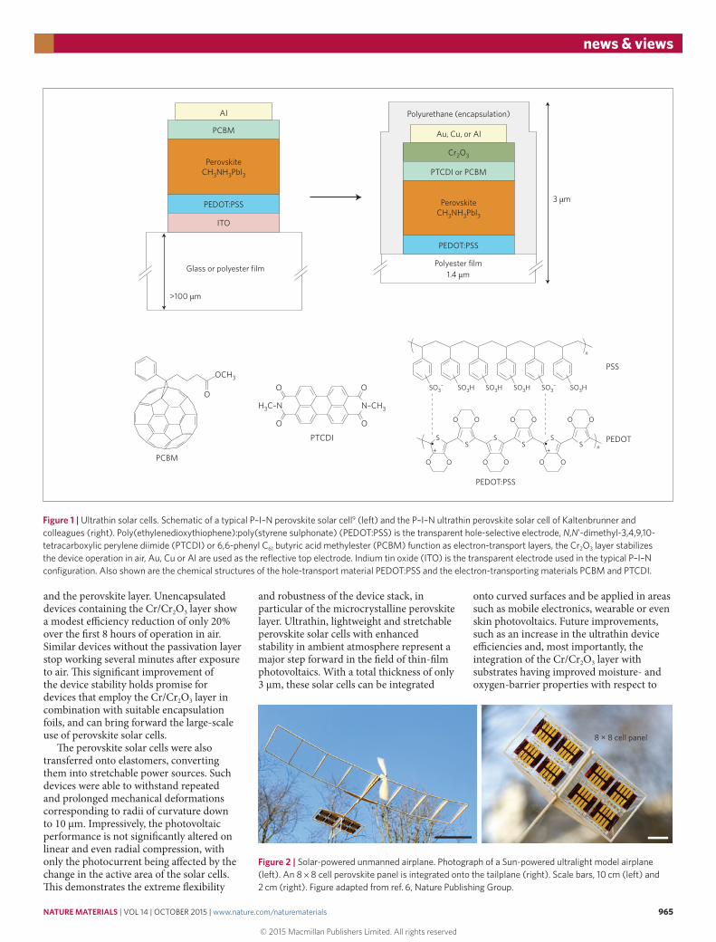
a (mesoscopic or flat) electron-transporting metal oxide and covered with an organic hole-transporting layer, or it is sandwiched between a bottom organic hole-transporting material and a top organic electron-transporting compound. These structures are commonly referred to as N–I–P and P–I–N, respectively, where N and P stand for n- and p-type carriers and I for the intrinsic (perovskite) layer. Kaltenbrunner and colleagues have employed the P–I–N architecture, yet have done so by using the bottom conducting polymer not only as the hole-selective transport layer but also as the electrode, eliminating the conducting metal oxide electrodes that are usually employed (Fig. 1). By processing the device on 1.4-μm-thick polyester foils (using glass as a carrier substrate), the total device thickness including the electrodes and top protecting layer is only 3 μm.
The researchers suggest that these ultrathin solar cells can pave the way for Sun-powered unmanned aerial vehicles, self-powered micro-aerial robotics or observation stations. To demonstrate that these applications are indeed possible, they prepared solar leaves, a Sun-powered propeller driven balloon and a Sun-powered model airplane (Fig. 2). All these demonstrators rely on a large number of
ultrathin perovskite solar cells assembled into 8-cell modules, with an average efficiency of 8.4%. Such high yield of working cells is a remarkable achievement considering that the polyester foils contain defects. One key processing parameter that helped achieve the high production yield is the addition of a high-boiling-point solvent, dimethyl sulfoxide (DMSO), to the hole-conducting polymer dispersion used to prepare the bottom electrode. The presence of DMSO in the conductive film aids in the nucleation of the perovskite crystallites, leading to the formation of a pinhole-free perovskite layer.
One of the remaining hurdles for the widespread use of perovskite solar cells is their sensitivity to moisture, which leads to a rapid degradation of the perovskite layer and hence a short device lifetime. To improve the stability of their perovskite solar cells, Kaltenbrunner and co-workers evaporated a thin layer of chromium on top of the electron-transport layer prior to the deposition of the top electrode. The conditions during the evaporation are such that the chromium is oxidized, forming a Cr/Cr2O3 layer on top of the perovskite. Cr2O3 is known for its robustness against aggressive oxidants and prevents chemical reactions between the top metal electrode
© 2015 Macmillan Publishers Limited. All rights reserved
NATURE MATERIALS | VOL 14 | OCTOBER 2015 | www.nature.com/naturematerials 965
news & views
and the perovskite layer. Unencapsulated devices containing the Cr/Cr2O3 layer show a modest efficiency reduction of only 20% over the first 8 hours of operation in air. Similar devices without the passivation layer stop working several minutes after exposure to air. This significant improvement of the device stability holds promise for devices that employ the Cr/Cr2O3 layer in combination with suitable encapsulation foils, and can bring forward the large-scale use of perovskite solar cells.
The perovskite solar cells were also transferred onto elastomers, converting them into stretchable power sources. Such devices were able to withstand repeated and prolonged mechanical deformations corresponding to radii of curvature down to 10 μm. Impressively, the photovoltaic performance is not significantly altered on linear and even radial compression, with only the photocurrent being affected by the change in the active area of the solar cells. This demonstrates the extreme flexibility
and robustness of the device stack, in particular of the microcrystalline perovskite layer. Ultrathin, lightweight and stretchable perovskite solar cells with enhanced stability in ambient atmosphere represent a major step forward in the field of thin-film photovoltaics. With a total thickness of only 3 μm, these solar cells can be integrated
onto curved surfaces and be applied in areas such as mobile electronics, wearable or even skin photovoltaics. Future improvements, such as an increase in the ultrathin device efficiencies and, most importantly, the integration of the Cr/Cr2O3 layer with substrates having improved moisture- and oxygen-barrier properties with respect to
Figure 1 | Ultrathin solar cells. Schematic of a typical P–I–N perovskite solar cell9 (left) and the P–I–N ultrathin perovskite solar cell of Kaltenbrunner and colleagues (right). Poly(ethylenedioxythiophene):poly(styrene sulphonate) (PEDOT:PSS) is the transparent hole-selective electrode, N,N’-dimethyl-3,4,9,10-tetracarboxylic perylene diimide (PTCDI) or 6,6-phenyl C61 butyric acid methylester (PCBM) function as electron-transport layers, the Cr2O3 layer stabilizes the device operation in air, Au, Cu or Al are used as the reflective top electrode. Indium tin oxide (ITO) is the transparent electrode used in the typical P–I–N configuration. Also shown are the chemical structures of the hole-transport material PEDOT:PSS and the electron-transporting materials PCBM and PTCDI.
PTCDI
O
O
O
N–CH3H3C–N
O
PEDOT:PSS
PCBMn
O O O O O O
O O
S S SSSS
O O O O
PSS
PEDOT
SO3– SO3
–SO3H SO3H SO3H SO3H
OCH3
O
n
+ +
PerovskiteCH3NH3Pbl3
PCBM
AI
PEDOT:PSS
ITO
>100 µm
3 µm
Au, Cu, or Al
Polyurethane (encapsulation)
PerovskiteCH3NH3Pbl3
PTCDI or PCBM
Cr2O3
PEDOT:PSS
Polyester filmGlass or polyester film1.4 µm
8 × 8 cell panel
Figure 2 | Solar-powered unmanned airplane. Photograph of a Sun-powered ultralight model airplane (left). An 8 × 8 cell perovskite panel is integrated onto the tailplane (right). Scale bars, 10 cm (left) and 2 cm (right). Figure adapted from ref. 6, Nature Publishing Group.
© 2015 Macmillan Publishers Limited. All rights reserved
966 NATURE MATERIALS | VOL 14 | OCTOBER 2015 | www.nature.com/naturematerials
news & views
polyester films, should lead to significantly improved device stability, which is needed for the introduction of perovskite solar cells into the market. ❐
Michele Sessolo and Henk J. Bolink are at the Instituto de Ciencia Molecular of the Universidad de Valencia, C/ Catedrático José Beltrán, 2,
46980 Paterna, Spain. e-mail: [email protected]; [email protected]
References1. Kojima, A., Teshima, K., Shirai, Y. & Miyasaka, T.
J. Am. Chem. Soc. 131, 6050–6051 (2009).2. Ball, J. M., Lee, M. M., Hey, A. & Snaith, H. J. Energy Environ. Sci.
6, 1739–1743 (2013).3. Gratzel, M. Nature Mater. 13, 838–842 (2014).
4. Yang, W. S. et al. Science 348, 1234–1237 (2015).5. Shin, S. S. et al. Nature Commun. 6, 7410 (2015).6. Kaltenbrunner, M. et al. Nature Mater. 14, 1032–1039 (2015).7. Burschka, J. et al. Nature 499, 316–319 (2013).8. Liu, M., Johnston, M. B. & Snaith, H. J. Nature
501, 395–398 (2013).9. Nie, W. et al. Science 347, 522–525 (2015).10. Malinkiewicz, O. et al. Nature Photon. 8, 128–132 (2014).
Published online: 24 August 2015
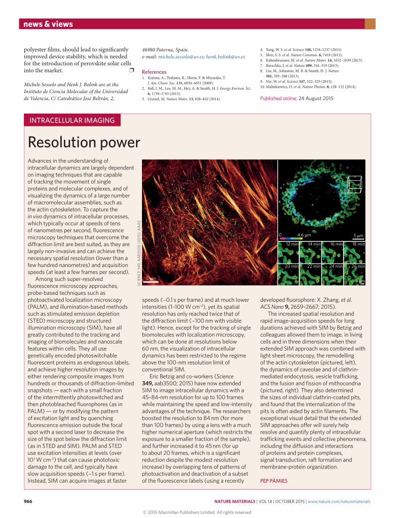
Advances in the understanding of intracellular dynamics are largely dependent on imaging techniques that are capable of tracking the movement of single proteins and molecular complexes, and of visualizing the dynamics of a large number of macromolecular assemblies, such as the actin cytoskeleton. To capture the in vivo dynamics of intracellular processes, which typically occur at speeds of tens of nanometres per second, fluorescence microscopy techniques that overcome the diffraction limit are best suited, as they are largely non-invasive and can achieve the necessary spatial resolution (lower than a few hundred nanometres) and acquisition speeds (at least a few frames per second).
Among such super-resolved fluorescence microscopy approaches, probe-based techniques such as photoactivated localization microscopy (PALM), and illumination-based methods such as stimulated emission depletion (STED) microscopy and structured illumination microscopy (SIM), have all greatly contributed to the tracking and imaging of biomolecules and nanoscale features within cells. They all use genetically encoded photoswitchable fluorescent proteins as endogenous labels, and achieve higher resolution images by either rendering composite images from hundreds or thousands of diffraction-limited snapshots — each with a small fraction of the intermittently photoswitched and then photobleached fluorophores (as in PALM) — or by modifying the pattern of excitation light and by quenching fluorescence emission outside the focal spot with a second laser to decrease the size of the spot below the diffraction limit (as in STED and SIM). PALM and STED use excitation intensities at levels (over 103 W cm–2) that can cause phototoxic damage to the cell, and typically have slow acquisition speeds (~1 s per frame). Instead, SIM can acquire images at faster
Resolution powerINTRACELLULAR IMAGING
speeds (~0.1 s per frame) and at much lower intensities (1–100 W cm–2), yet its spatial resolution has only reached twice that of the diffraction limit (~100 nm with visible light). Hence, except for the tracking of single biomolecules with localization microscopy, which can be done at resolutions below 60 nm, the visualization of intracellular dynamics has been restricted to the regime above the 100-nm resolution limit of conventional SIM.
Eric Betzig and co-workers (Science 349, aab3500; 2015) have now extended SIM to image intracellular dynamics with a 45–84-nm resolution for up to 100 frames while maintaining the speed and low-intensity advantages of the technique. The researchers boosted the resolution to 84 nm (for more than 100 frames) by using a lens with a much higher numerical aperture (which restricts the exposure to a smaller fraction of the sample), and further increased it to 45 nm (for up to about 20 frames, which is a significant reduction despite the modest resolution increase) by overlapping tens of patterns of photoactivation and deactivation of a subset of the fluorescence labels (using a recently
developed fluorophore: X. Zhang, et al. ACS Nano 9, 2659–2667; 2015).
The increased spatial resolution and rapid image-acquisition speeds for long durations achieved with SIM by Betzig and colleagues allowed them to image, in living cells and in three dimensions when their extended SIM approach was combined with light sheet microscopy, the remodelling of the actin cytoskeleton (pictured, left), the dynamics of caveolae and of clathrin-mediated endocytosis, vesicle trafficking, and the fusion and fission of mithocondria (pictured, right). They also determined the sizes of individual clathrin-coated pits, and found that the internalization of the pits is often aided by actin filaments. The exceptional visual detail that the extended SIM approaches offer will surely help resolve and quantify plenty of intracellular trafficking events and collective phenomena, including the diffusion and interactions of proteins and protein complexes, signal transduction, raft formation and membrane-protein organization.
PEP PÀMIES
SCIE
NC
E 34
9, A
AB3
500
(201
5); A
AA
S
0 4.6 μm
5 μm
5 μm
1 μm
12 min
20 min 22 min 24 min 26 min
14 min 16 min 18 min
© 2015 Macmillan Publishers Limited. All rights reserved


![System analysis of a PV/T hybrid solar · PDF fileintroduced in the construction to focus radiation onto the solar cells. ... σ Stefan-Boltzmann constant [W/m²K4] m ... issues and](https://static.fdocument.org/doc/165x107/5aba47bf7f8b9a567c8b53b5/system-analysis-of-a-pvt-hybrid-solar-in-the-construction-to-focus-radiation-onto.jpg)