Meshing - Ship Lab – Ship Design and Operation Lab ... · PDF fileMeshing The mesh...
36
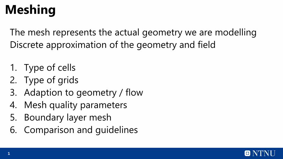
1 Meshing The mesh represents the actual geometry we are modelling Discrete approximation of the geometry and field 1. Type of cells 2. Type of grids 3. Adaption to geometry / flow 4. Mesh quality parameters 5. Boundary layer mesh 6. Comparison and guidelines
Transcript of Meshing - Ship Lab – Ship Design and Operation Lab ... · PDF fileMeshing The mesh...
1
Meshing
The mesh represents the actual geometry we are modelling
Discrete approximation of the geometry and field
1. Type of cells
2. Type of grids
3. Adaption to geometry / flow
4. Mesh quality parameters
5. Boundary layer mesh
6. Comparison and guidelines
2
Meshing
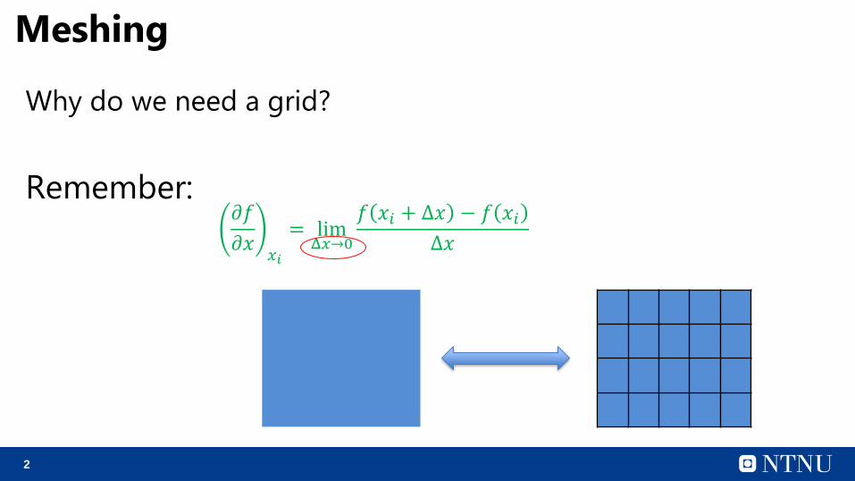
Why do we need a grid?
Remember: 𝜕𝑓
𝜕𝑥𝑥𝑖
= limΔ𝑥→0
𝑓 𝑥𝑖 + Δ𝑥 − 𝑓 𝑥𝑖Δ𝑥
3
Meshing
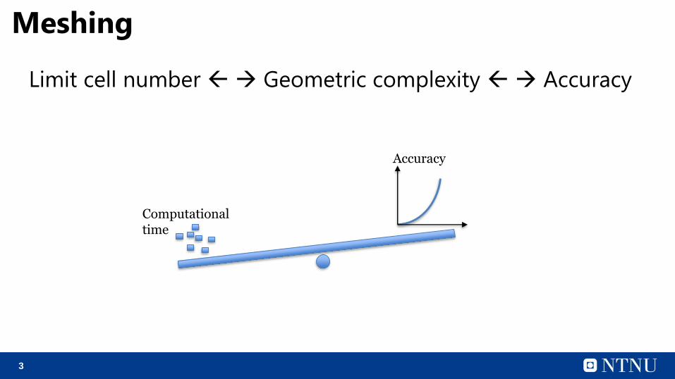
Limit cell number Geometric complexity Accuracy
Computational time
Accuracy
4
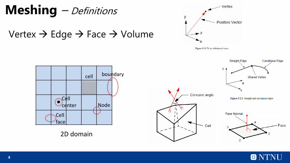
Meshing – Definitions
Vertex Edge Face Volume
2D domain
cell
Cell face
Cell center Node
boundary
5
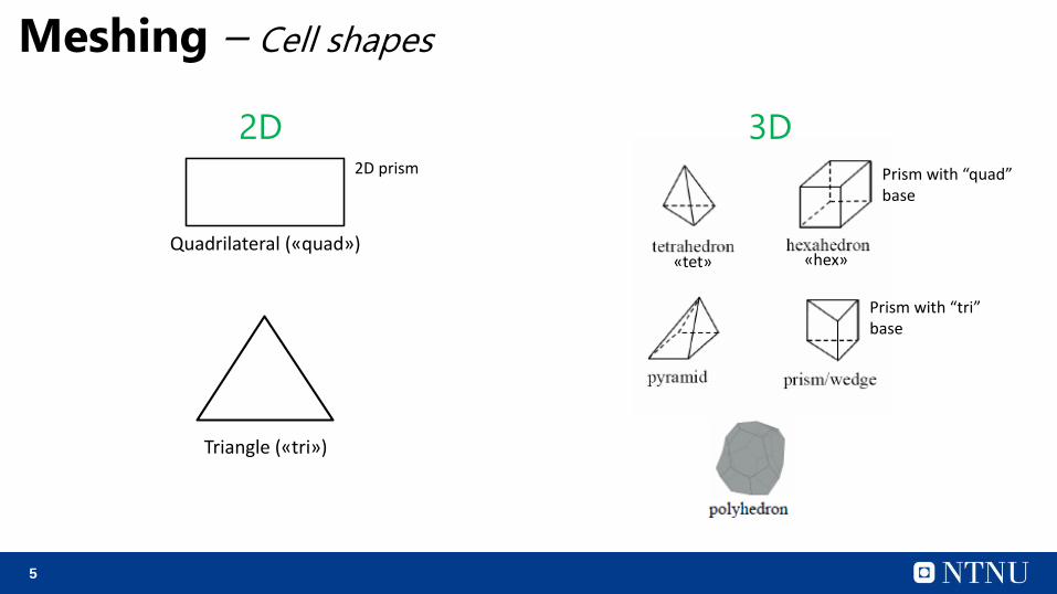
Meshing – Cell shapes
Quadrilateral («quad»)
Triangle («tri»)
«tet» «hex»
Prism with “quad”base
2D prism
Prism with “tri”base
2D 3D
6
Meshing – Cell shapes
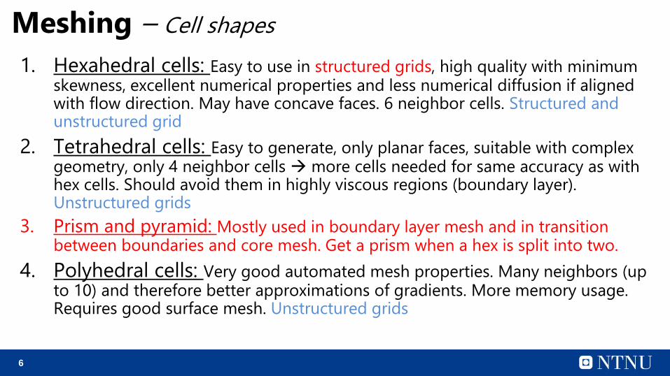
1. Hexahedral cells: Easy to use in structured grids, high quality with minimum skewness, excellent numerical properties and less numerical diffusion if aligned with flow direction. May have concave faces. 6 neighbor cells. Structured and unstructured grid
2. Tetrahedral cells: Easy to generate, only planar faces, suitable with complex geometry, only 4 neighbor cells more cells needed for same accuracy as with hex cells. Should avoid them in highly viscous regions (boundary layer). Unstructured grids
3. Prism and pyramid: Mostly used in boundary layer mesh and in transition between boundaries and core mesh. Get a prism when a hex is split into two.
4. Polyhedral cells: Very good automated mesh properties. Many neighbors (up to 10) and therefore better approximations of gradients. More memory usage. Requires good surface mesh. Unstructured grids
7
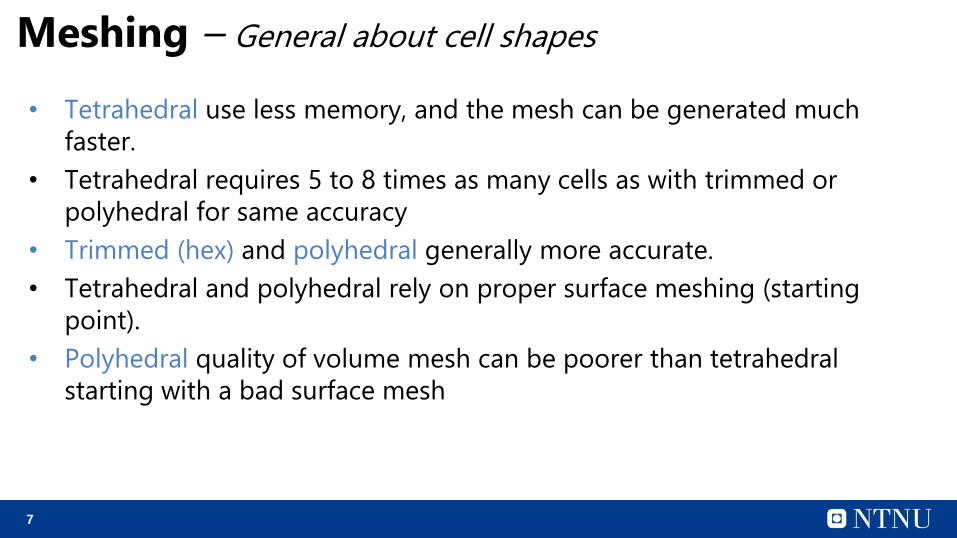
Meshing – General about cell shapes
• Tetrahedral use less memory, and the mesh can be generated much
faster.
• Tetrahedral requires 5 to 8 times as many cells as with trimmed or
polyhedral for same accuracy
• Trimmed (hex) and polyhedral generally more accurate.
• Tetrahedral and polyhedral rely on proper surface meshing (starting
point).
• Polyhedral quality of volume mesh can be poorer than tetrahedral
starting with a bad surface mesh
8
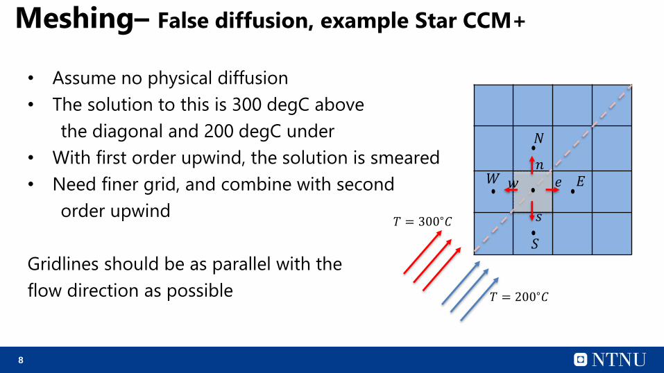
Meshing– False diffusion, example Star CCM+
• Assume no physical diffusion
• The solution to this is 300 degC above
the diagonal and 200 degC under
• With first order upwind, the solution is smeared
• Need finer grid, and combine with second
order upwind
Gridlines should be as parallel with the
flow direction as possible
𝑇 = 300∘𝐶
𝑇 = 200∘𝐶
𝑊 𝐸
𝑁
𝑆
𝑛𝑤 𝑒
𝑠
9
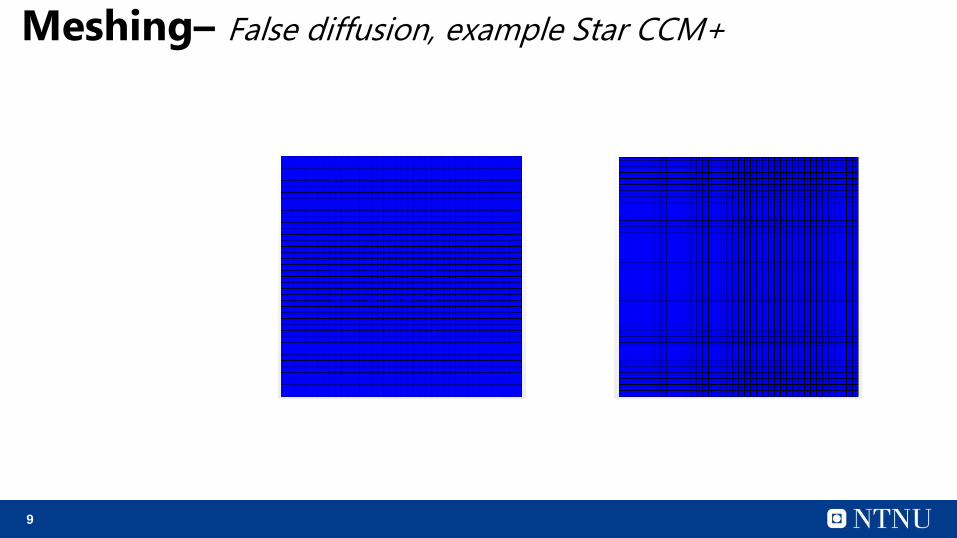
Meshing– False diffusion, example Star CCM+
10
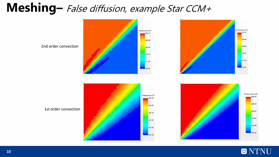
Meshing– False diffusion, example Star CCM+
2nd order convection
1st order convection
11
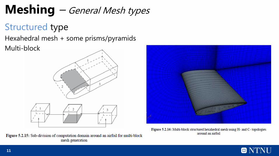
Meshing – General Mesh types
Structured typeHexahedral mesh + some prisms/pyramids
Multi-block
12
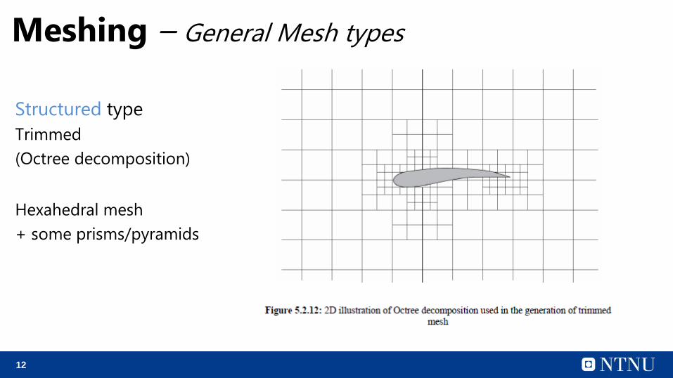
Meshing – General Mesh types
Structured type
Trimmed
(Octree decomposition)
Hexahedral mesh
+ some prisms/pyramids
13
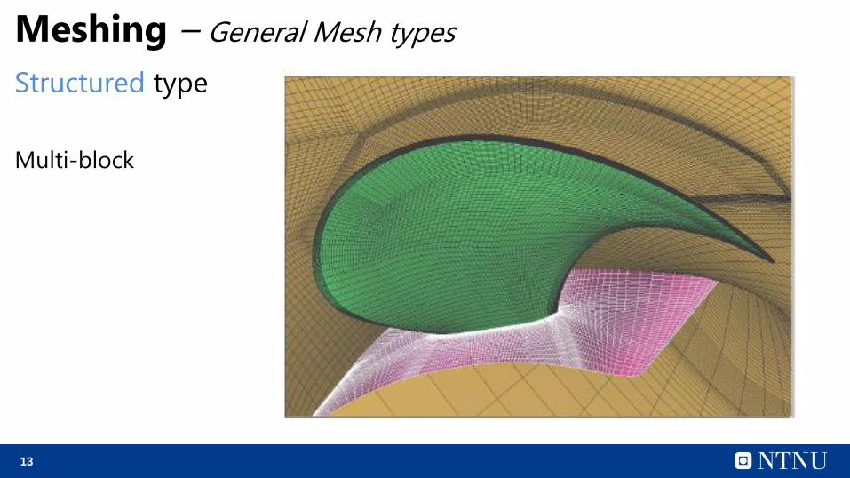
Meshing – General Mesh types
Structured type
Multi-block
14
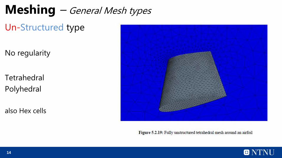
Meshing – General Mesh types
Un-Structured type
No regularity
Tetrahedral
Polyhedral
also Hex cells
15
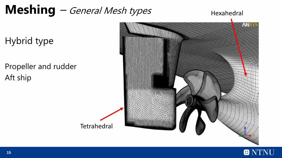
Meshing – General Mesh types
Hybrid type
Propeller and rudder
Aft ship
Tetrahedral
Hexahedral
16
Meshing – General Mesh types
Structured grid: Gridlines of same family do not cross each other, cross the other family gridlines only ones.
Cartesian mesh is the simplest form with one block of hexahedral cells.
Curvilinear gridlines to account for geometry with curved edges.
Multi-block to get good grid. O-, H- and C- grid.
More time consuming to generate, but offers increased accuracy
More difficult to adapt it to the actual CAD model
Surface mesh just a byproduct from volume mesh, need good CAD quality
Surface re-meshing should be used
17
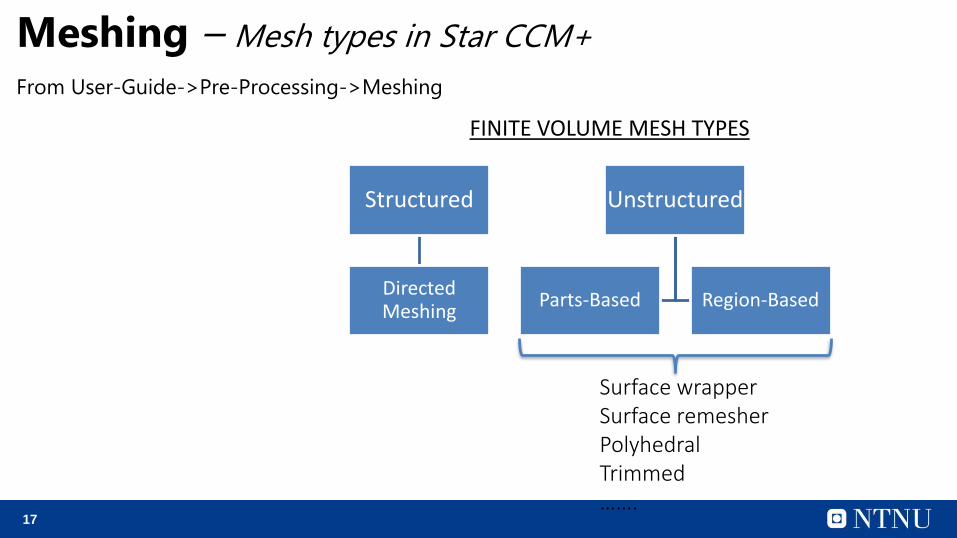
Meshing – Mesh types in Star CCM+
From User-Guide->Pre-Processing->Meshing
Structured
DirectedMeshing
Unstructured
Parts-Based Region-Based
FINITE VOLUME MESH TYPES
Surface wrapperSurface remesherPolyhedralTrimmed…….
18
19
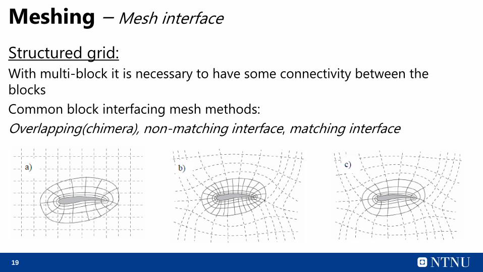
Meshing – Mesh interface
Structured grid:
With multi-block it is necessary to have some connectivity between the
blocks
Common block interfacing mesh methods:
Overlapping(chimera), non-matching interface, matching interface
20
Meshing – Mesh interface
The same as previous slide is true with multi-region mesh of
unstructured type and hybrid mesh.
If the mesh between regions of different mesh is non-
conformal, should check if the solver can handle this.
Star CCM+ tries to mesh conformal automatically. If not, can
modify the CAD model
21
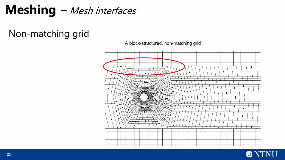
Meshing – Mesh interfaces
Non-matching grid
22
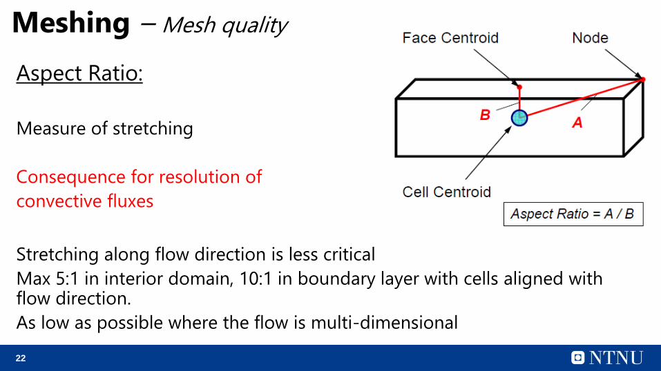
Meshing – Mesh quality
Aspect Ratio:
Measure of stretching
Consequence for resolution of
convective fluxes
Stretching along flow direction is less critical
Max 5:1 in interior domain, 10:1 in boundary layer with cells aligned with flow direction.
As low as possible where the flow is multi-dimensional
23
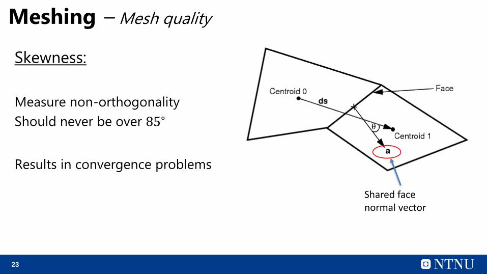
Meshing – Mesh quality
Skewness:
Measure non-orthogonality
Should never be over 85∘
Results in convergence problems
Shared face normal vector
24
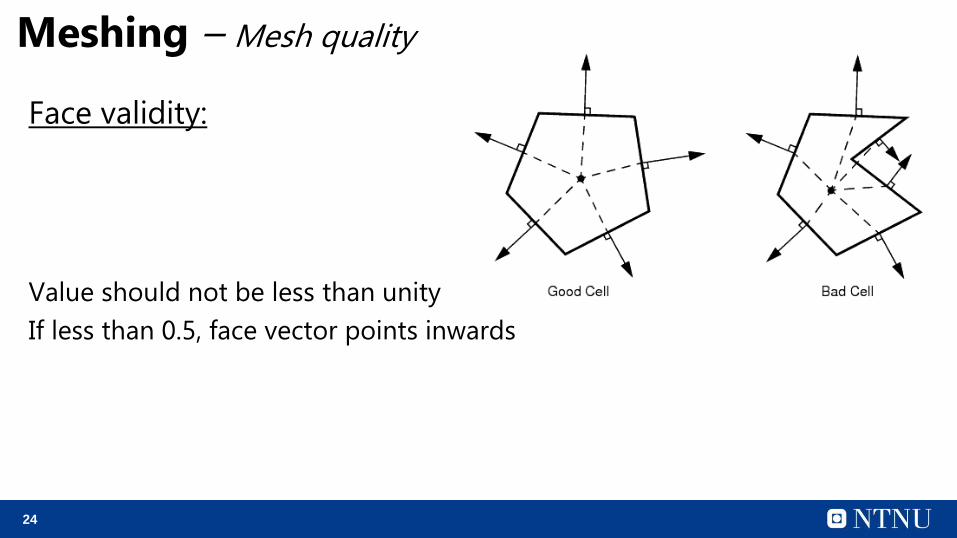
Meshing – Mesh quality
Face validity:
Value should not be less than unity
If less than 0.5, face vector points inwards
25
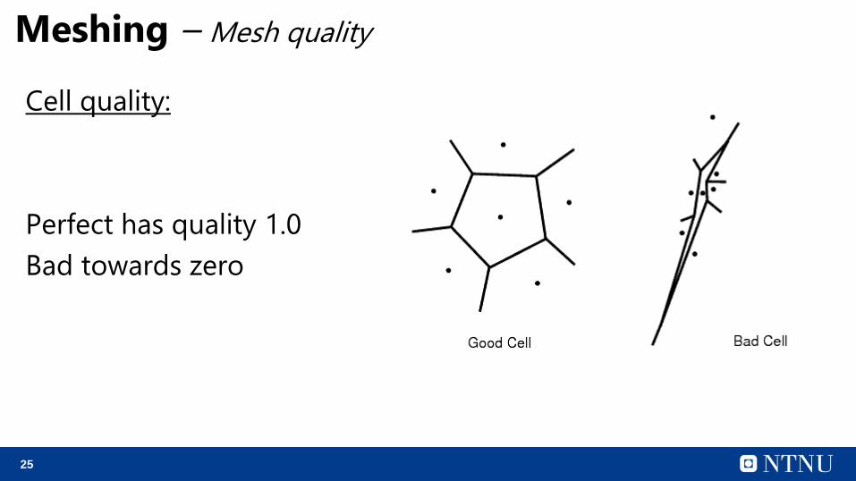
Meshing – Mesh quality
Cell quality:
Perfect has quality 1.0
Bad towards zero
26
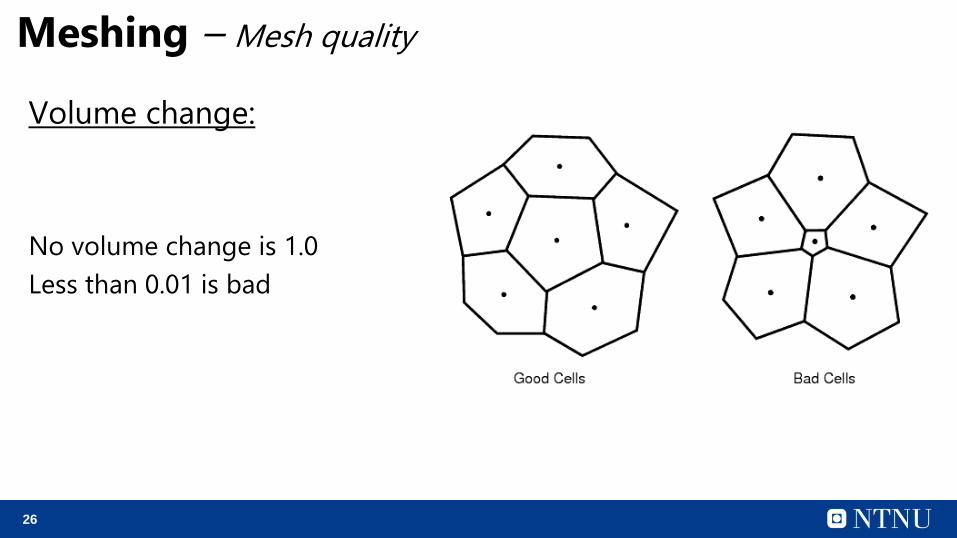
Meshing – Mesh quality
Volume change:
No volume change is 1.0
Less than 0.01 is bad
27
Meshing – Mesh quality
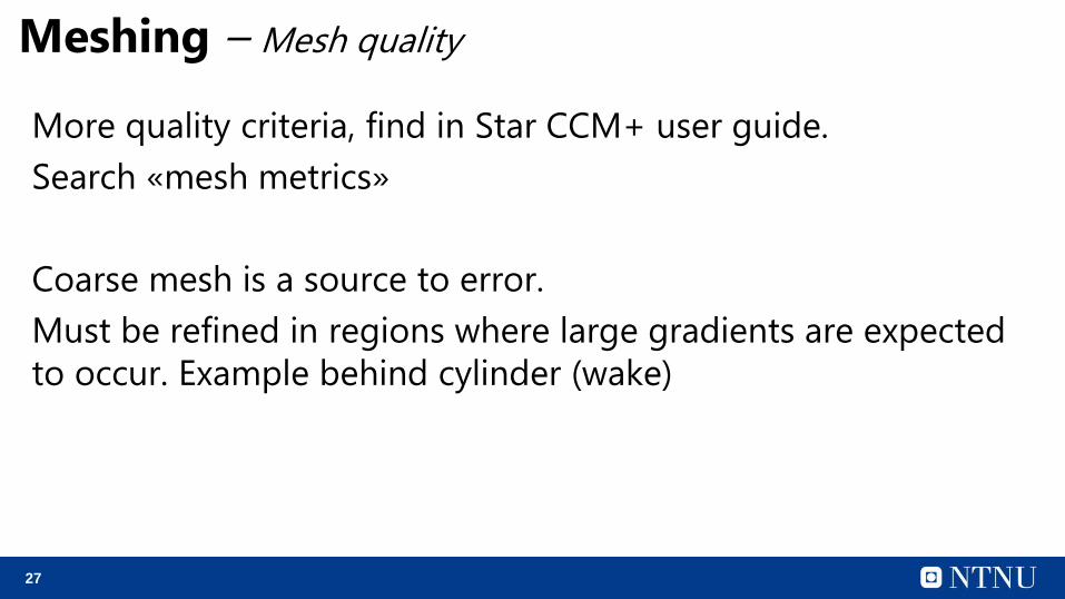
More quality criteria, find in Star CCM+ user guide.
Search «mesh metrics»
Coarse mesh is a source to error.
Must be refined in regions where large gradients are expected
to occur. Example behind cylinder (wake)
28
Meshing – Boundary layer mesh
Turbulent boundary layers can be modelled by semi-empirical
approach or entirely resolved.
In the first approach, wall functions are used to predict the
inner part of the boundary layer, called the viscous sub-layer
and buffer layer. This means the mesh can be coarser, since the
inner part of the boundary layer is not resolved.
In the second approach, the entire boundary layer is modelled.
A much finer mesh is required.
29
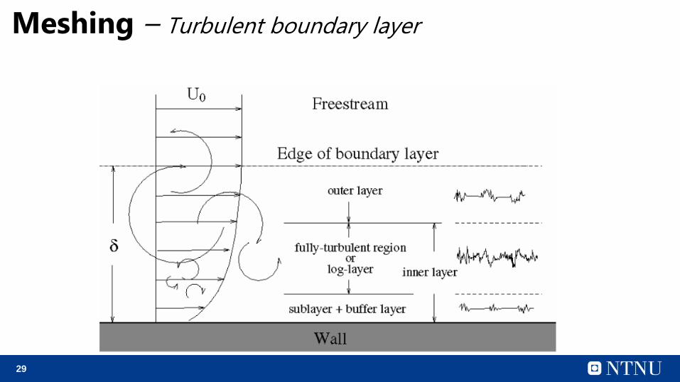
Meshing – Turbulent boundary layer
30
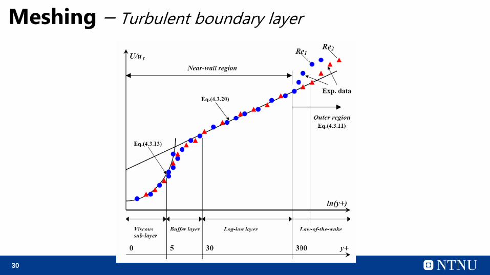
Meshing – Turbulent boundary layer
31
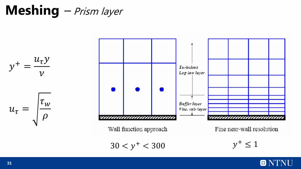
Meshing – Prism layer
𝑦+ =𝑢𝜏𝑦
𝜈
𝑢𝜏 =𝜏𝑤𝜌
30 < 𝑦+ < 300 𝑦+ ≤ 1
32
Meshing – Prism layer
In Star CCM+ there is an enhanced y+ wall treatment (All y+
wall treatment), which makes an adequate solution for both
cases. This makes it easier for the user.
Still it is recommended that the y+ value do not exceed the
upper limit of y+ values with wall functions (200-300).
33
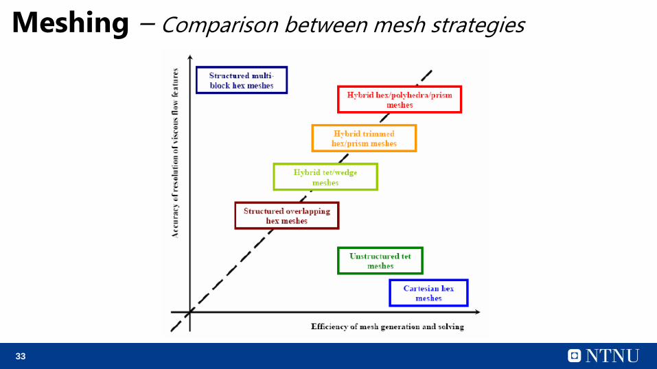
Meshing – Comparison between mesh strategies
34
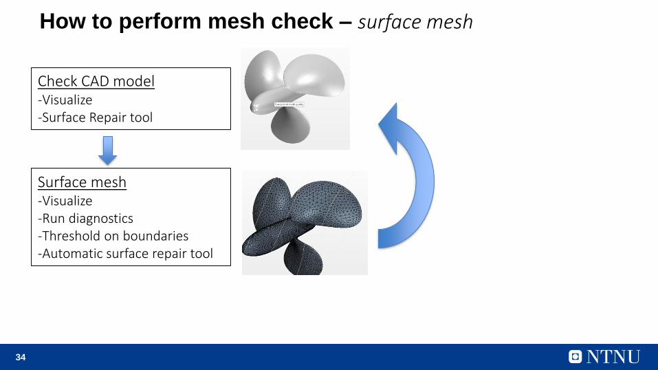
How to perform mesh check – surface mesh
Check CAD model-Visualize-Surface Repair tool
Surface mesh-Visualize-Run diagnostics-Threshold on boundaries-Automatic surface repair tool
35
Meshing – General Guidelines
1. Clean CAD model
2. Reduce cell skew, especially on hex cells. Should be less than 85 deg
3. Angle of gridlines on outer boundary of mesh should be close to 90
degrees
4. Avoid tetrahedral cells in the wall boundary layer
5. In the interior (away from boundaries) aspect ratio less than 20
6. Parallel alignment with flow if it is possible to predict
7. 5-10 layers of boundary cells (prism layers). If no wall function is used,
and low Re flow, must have many more cells (15 cells).
8. As long as the surface geometry is well predicted, and the flow direction
is fairly parallel, use “hex” mesh (trimmed)
36
Meshing – Conclusion
• A structured mesh is most accurate. It is much more time
consuming to generate for complex geometry.
• Unstructured mesh is efficient to generate, use less memory.
Using tetrahedral cells is not as accurate, and need more
cells to produce same accuracy.
• Hybrid mesh can be a good compromise