
Materials Science & Engineering Aengineering.snu.ac.kr/pdf/2014(15)/2014_ATH_Strain-induced e... ·...
6
Strain-induced ε-martensite transformation during nanoindentation of high-nitrogen steel Tae-Hong Ahn a,1 , Sung Bo Lee a , Kyung-Tae Park b , Kyu Hwan Oh a , Heung Nam Han a,n a Department of Materials Science and Engineering and Center for Iron and Steel Research, RIAM, Seoul National University, Seoul 151-744, Republic of Korea b Division of Advanced Materials Science and Engineering, Hanbat National University, Daejeon 305-719, Republic of Korea article info Article history: Received 21 November 2013 Received in revised form 10 January 2014 Accepted 11 January 2014 Available online 21 January 2014 Keywords: Nanoindentation Pop-in ε-martensite Shockley partial dislocation High-nitrogen stainless steel abstract The strain-induced austenite-to-ε-martensite transformation during nanoindentation of metastable austenite in a high-nitrogen stainless steel was investigated by observation of the microstructural changes underneath the indent. In the nanoindentation load–displacement curve, several small pop-ins were detected at the beginning stage of plastic deformation. The presence of ε-martensite bands underneath the indent and their orientation relationship with the parent austenite strongly suggest that the pop-ins in the load–displacement curve correspond to the transformation from austenite to ε- martensite. A quantitative analysis on the massive movement of Shockley partial dislocations during the transformation was performed to obtain the contraction strain under compressive stress conditions during nanoindentation. It was confirmed that the calculated contraction strain along the indenting direction matches well with the measured length of the pop-ins. & 2014 Elsevier B.V. All rights reserved. 1. Introduction It is well known that the deformation microstructure of a face- centered cubic (FCC) material depends on its stacking fault energy (SFE), which is closely related to the dissociation of perfect dislocation into Shockley partial dislocations [1,2]. Because the partial dislocations are preferable to the perfect dislocations when SFE is low, strain-induced ε-martensite (hexagonal close-packed, HCP) or deformation twinning dominates the early stage of plasticity, while dislocation cells or cross-slip are mainly observed in high-SFE materials [1–4]. It is known that even if there can be variation in SFE depending on alloying elements and their chemical composition, the SFE of conventional austenitic stainless steels generally has a value of 10–50 mJ m 2 [3–7], which is in a relatively low range. A recent systematic investigation on high-nitrogen steels [7] has shown that the deformation microstructure of austenitic alloys can be classified into three categories: (i) strain-induced martensitic transformations (ε- and α 0 -martensite) in low-SFE alloys (below 15 mJ m 2 ), (ii) deformation twinning in high-SFE alloys (above 20 mJ m 2 ), and (iii) the coexistence of martensitic transformation and deformation twinning in intermediate-SFE alloys (15–20 mJ m 2 ). In the case of category (i), ε-martensite first forms in an early stage of plastic deformation, and then it transforms into α 0 -martensite as deforma- tion proceeds. The ε-martensite transformation in steel has been extensively studied since Sato et al. [8] first found that Fe-based alloys show an outstanding shape memory effect associated with reversible γ (FCC) 2ε (HCP) phase transformation. As shown in Fig. 1, the γ-ε phase transformation occurs by motion of a γ /6/112S Shockley partial dislocations along each second {111} plane, where a γ is the lattice parameter of the austenite (FCC). The crystallographic relationship between γ and ε is {111} γ //{0001} ε and /1 10S γ ///11 20S ε , which is known as the Shoji–Nishiyama (S–N) orientation relationship [9]. Due to the crystal symmetries of each structure, 12 equivalent variants are possible for a given orientation relationship. Therefore, the total amount of shear will vary depending on what direction of Shockley partials is activated to make the HCP structure when the transformation occurs [10–12]. For instance, if the probability of the three faulting directions in the {111} plane is the same, no macro- scopic shape change will appear as the total sum of the shear strains by the three individual variants becomes zero. This ideal case of equal selection is often called “self-accommodated stacking”. On the other hand, the largest shear will take place when all stacking faults are made along one direction. This “monopartial stacking" produces the homogeneous shear of 1/2√ 2( 0.35) with a shear angle of 19.471. Thermally produced ε-martensite is likely to have the self- accommodated stacking form, whereas strain-induced ε-martensite appears as a monopartial stacking form [10–14]. Nanoindentation is a useful method to measure such solid-state phase transformations that introduce instantaneous strain [15]. Once a material experiences a sudden geometrical softening during Contents lists available at ScienceDirect journal homepage: www.elsevier.com/locate/msea Materials Science & Engineering A 0921-5093/$ - see front matter & 2014 Elsevier B.V. All rights reserved. http://dx.doi.org/10.1016/j.msea.2014.01.030 n Corresponding author. Tel.: þ82 2 880 9240; fax: þ82 2 872 8785. E-mail address: [email protected] (H.N. Han). 1 Present address: Technical Research Laboratories, POSCO, Gwangyang, Jeonnam 545-090, Republic of Korea. Materials Science & Engineering A 598 (2014) 56–61
Transcript of Materials Science & Engineering Aengineering.snu.ac.kr/pdf/2014(15)/2014_ATH_Strain-induced e... ·...
Strain-induced ε-martensite transformation during nanoindentationof high-nitrogen steel
Tae-Hong Ahn a,1, Sung Bo Lee a, Kyung-Tae Park b, Kyu Hwan Oh a, Heung Nam Han a,n
a Department of Materials Science and Engineering and Center for Iron and Steel Research, RIAM, Seoul National University, Seoul 151-744, Republic of Koreab Division of Advanced Materials Science and Engineering, Hanbat National University, Daejeon 305-719, Republic of Korea
a r t i c l e i n f o
Article history:Received 21 November 2013Received in revised form10 January 2014Accepted 11 January 2014Available online 21 January 2014
Keywords:NanoindentationPop-inε-martensiteShockley partial dislocationHigh-nitrogen stainless steel
a b s t r a c t
The strain-induced austenite-to-ε-martensite transformation during nanoindentation of metastableaustenite in a high-nitrogen stainless steel was investigated by observation of the microstructuralchanges underneath the indent. In the nanoindentation load–displacement curve, several small pop-inswere detected at the beginning stage of plastic deformation. The presence of ε-martensite bandsunderneath the indent and their orientation relationship with the parent austenite strongly suggest thatthe pop-ins in the load–displacement curve correspond to the transformation from austenite to ε-martensite. A quantitative analysis on the massive movement of Shockley partial dislocations during thetransformation was performed to obtain the contraction strain under compressive stress conditionsduring nanoindentation. It was confirmed that the calculated contraction strain along the indentingdirection matches well with the measured length of the pop-ins.
& 2014 Elsevier B.V. All rights reserved.
1. Introduction
It is well known that the deformation microstructure of a face-centered cubic (FCC) material depends on its stacking fault energy(SFE), which is closely related to the dissociation of perfectdislocation into Shockley partial dislocations [1,2]. Because thepartial dislocations are preferable to the perfect dislocations whenSFE is low, strain-induced ε-martensite (hexagonal close-packed,HCP) or deformation twinning dominates the early stage ofplasticity, while dislocation cells or cross-slip are mainly observedin high-SFE materials [1–4].
It is known that even if there can be variation in SFE dependingon alloying elements and their chemical composition, the SFEof conventional austenitic stainless steels generally has a value of10–50 mJ m�2 [3–7], which is in a relatively low range. A recentsystematic investigation on high-nitrogen steels [7] has shown thatthe deformation microstructure of austenitic alloys can be classifiedinto three categories: (i) strain-induced martensitic transformations(ε- and α0-martensite) in low-SFE alloys (below 15 mJ m�2), (ii)deformation twinning in high-SFE alloys (above 20 mJ m�2), and(iii) the coexistence of martensitic transformation and deformationtwinning in intermediate-SFE alloys (15–20 mJ m�2). In the case ofcategory (i), ε-martensite first forms in an early stage of plastic
deformation, and then it transforms into α0-martensite as deforma-tion proceeds.
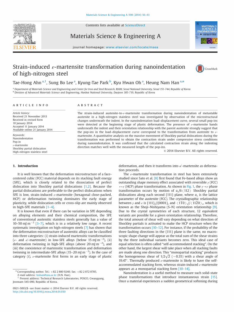
The ε-martensite transformation in steel has been extensivelystudied since Sato et al. [8] first found that Fe-based alloys show anoutstanding shape memory effect associated with reversible γ (FCC)2ε (HCP) phase transformation. As shown in Fig. 1, the γ-ε phasetransformation occurs by motion of aγ/6/112S Shockley partialdislocations along each second {111} plane, where aγ is the latticeparameter of the austenite (FCC). The crystallographic relationshipbetween γ and ε is {111}γ//{0001}ε and /110Sγ///1120Sε, which isknown as the Shoji–Nishiyama (S–N) orientation relationship [9].Due to the crystal symmetries of each structure, 12 equivalentvariants are possible for a given orientation relationship. Therefore,the total amount of shear will vary depending on what direction ofShockley partials is activated to make the HCP structure when thetransformation occurs [10–12]. For instance, if the probability of thethree faulting directions in the {111} plane is the same, no macro-scopic shape change will appear as the total sum of the shear strainsby the three individual variants becomes zero. This ideal case ofequal selection is often called “self-accommodated stacking”. On theother hand, the largest shear will take place when all stacking faultsare made along one direction. This “monopartial stacking" producesthe homogeneous shear of 1/2√2 (�0.35) with a shear angle of19.471. Thermally produced ε-martensite is likely to have the self-accommodated stacking form, whereas strain-induced ε-martensiteappears as a monopartial stacking form [10–14].
Nanoindentation is a useful method to measure such solid-statephase transformations that introduce instantaneous strain [15].Once a material experiences a sudden geometrical softening during
Contents lists available at ScienceDirect
journal homepage: www.elsevier.com/locate/msea
Materials Science & Engineering A
0921-5093/$ - see front matter & 2014 Elsevier B.V. All rights reserved.http://dx.doi.org/10.1016/j.msea.2014.01.030
n Corresponding author. Tel.: þ82 2 880 9240; fax: þ82 2 872 8785.E-mail address: [email protected] (H.N. Han).1 Present address: Technical Research Laboratories, POSCO, Gwangyang,
Jeonnam 545-090, Republic of Korea.
Materials Science & Engineering A 598 (2014) 56–61
load-controlled indentation, the indenter tip must react rapidly inorder to maintain a constant loading rate. The motion of theindenter tip will be detected as a flat segment of the nanoindenta-tion loading curve, and this sudden displacement excursion is calleda “pop-in” [15–18]. Recently, Misra et al. [19] and Sekido et al. [20]suggested that the γ-ε phase transformation can be detected asnanoindentation pop-in, but quantitative examinations have notbeen achieved. In this study, the mechanical response and themicrostructural changes of a high-nitrogen stainless steel wereinvestigated by nanoindentation and high-resolution transmissionelectron microscopy (HRTEM). A quantitative analysis of the mas-sive movement of Shockley partial dislocations during the transfor-mation was performed to obtain the length of pop-in under acompressive stress condition during nanoindentation. The
calculated length was compared to the measured ones consideringthe microstructure obtained from HRTEM.
2. Experimental
The material used in this study was a high-nitrogen alloyedsteel with the chemical composition of Fe–0.02C–5.06Mn–0.19Si–0.23Ni–0.28N–20.08Cr (in wt%). The stacking fault energy ofaustenite in this alloy is estimated to be lower than �20 mJ m�2
by deducting it from the recent literatures, with which the initialdeformation microstructure is expected to be ε-martensite [7,21].The microstructure changes during macroscopic tensile tests wereobserved by TEM at 5%, 10% and 40% tensile strain.
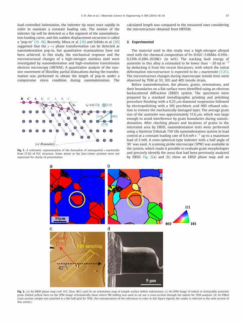
Before nanoindentation, the phases, grains, orientations, andtheir boundaries on a flat surface were identified using an electronbackscattered diffraction (EBSD) system. The specimens wereprepared by a standard metallographic grinding and polishingprocedure finishing with a 0.25 mm diamond suspension followedby electropolishing with a 10% perchloric acid–90% ethanol solu-tion to remove the mechanically damaged layer. The average grainsize of the austenite was approximately 15.6 μm, which was largeenough to avoid interference by grain boundaries during nanoin-dentation. After checking phases and locations of grains in theinterested area by EBSD, nanoindentation tests were performedusing a Hysitron TriboLab 750 Ubi nanoindentation system in loadcontrol at a constant loading rate of 0.4 mN s�1 up to a maximumload of 2 mN. A cono-spherical-type indenter with a half angle of301 was used. A scanning probe microscope (SPM) was available inthe system, which made it possible to evaluate grain morphologiesand precisely identify the areas that had been previously analyzedby EBSD. Fig. 2(a) and (b) show an EBSD phase map and an
Fig. 1. A schematic representation of the formation of monopartial ε-martensitefrom [110] of FCC structure. Some atoms at the face-center position were notexpressed for clarity of presentation.
Fig. 2. (a) An EBSD phase map (red: FCC, blue: BCC) and (b) an orientation map of sample surface before indentation. (c) An SPM image of indent in metastable austenitegrain. Dotted yellow lines on the SPM image schematically show where FIB milling was used to cut out a cross-section through the indent for TEM analysis. (d) An FIBedcross-section sample was attached to a Mo half-grid for TEM. (For interpretation of the references to color in this figure legend, the reader is referred to the web version ofthis article.)
T.-H. Ahn et al. / Materials Science & Engineering A 598 (2014) 56–61 57
orientation map obtained before nanoindentation, respectively.The circled austenite grain in the figures is the same as that at thecenter with an indentation mark in the SPM image in Fig. 2(c).
Cross-sectional HRTEM analysis of the indented specimen wasperformed to check for ε-martensite in the deformed region underthe indent. All TEM specimens examined were prepared on afocused ion beam (FIB) workstation (FEI Nova 200 Nanolab dual-beam FIB). Along the yellow dotted lines marked in Fig. 2(c), cross-section lamellae approximately 10 μm wide and 5 μm deep werelifted out and attached to a Mo half-grid that fit in the TEM holder(Fig. 2(d)). Because ε-martensite and parent austenite have aconfined S–N orientation relationship, a cross-section sample ofwhich the normal is nearly parallel to /110Sγ was prepared asshown in Fig. 2(c) in order to directly observe the orientationalrelationship and stacking faults by a/6/112Sγ partial dislocationsin an edge-on view. The prepared specimens were examined withfield-emission TEM (Tecnai G2 F30 S-Twin, FEI) at 300 keV (0.2-nmpoint-to-point resolution).
3. Results and discussion
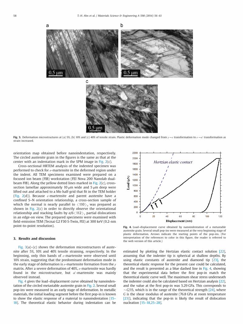
Fig. 3(a)–(c) shows the deformation microstructures of auste-nite after 5%, 10% and 40% tensile straining, respectively. In thebeginning, only thin bands of ε-martensite were observed until10% strain, suggesting that the predominant deformation mode inthe early stage of deformation is ε-martensite formation from the γmatrix. After a severe deformation of 40%, ε-martensite was hardlyfound in the microstructure, but α0-martensite was mainlyobserved instead.
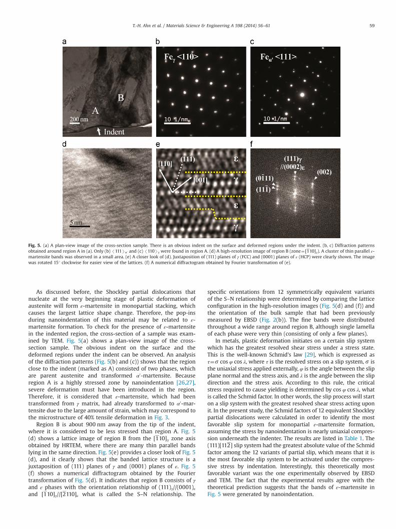
Fig. 4 gives the load–displacement curve obtained by nanoinden-tation of the circled metastable austenite grain in Fig. 2. Several smallpop-ins were measured in an early stage of deformation. In metallicmaterials, the initial loading segment before the first pop-in is knownto show the elastic response of a material to nanoindentation [15–18]. The theoretical elastic behavior during indentation can be
estimated by plotting the Hertzian elastic contact solution [22],assuming that the indenter tip is spherical at shallow depths. Byusing elastic constants of austenite and diamond tip [23], thetheoretical elastic response for the present case could be calculated,and the result is presented as a blue dashed line in Fig. 4, showingthat the experimental data before the first pop-in match thetheoretical elastic curve well. The maximum shear stress underneaththe indenter could also be calculated based on Hertzian analysis [22],and the value at the first pop-in was 5.29 GPa. This corresponds to�G/15, which is in the range of the theoretical strength [24], whereG is the shear modulus of austenite (76.8 GPa at room temperature[23]), indicating that the pop-in is likely the result of dislocationnucleation [15–18,25–28].
Fig. 3. Deformation microstructures at (a) 5%, (b) 10% and (c) 40% of tensile strain. Plastic deformation mode changed from γ-ε transformation to ε-α0 transformation asstrain increased.
Fig. 4. Load–displacement curve obtained by nanoindentation of a metastableaustenite grain. Several small pop-ins were measured at the very beginning stage ofplastic deformation. Arrows indicate the starting points of the pop-ins. (Forinterpretation of the references to color in this figure, the reader is referred tothe web version of this article.)
T.-H. Ahn et al. / Materials Science & Engineering A 598 (2014) 56–6158
As discussed before, the Shockley partial dislocations thatnucleate at the very beginning stage of plastic deformation ofaustenite will form ε-martensite in monopartial stacking, whichcauses the largest lattice shape change. Therefore, the pop-insduring nanoindentation of this material may be related to ε-martensite formation. To check for the presence of ε-martensitein the indented region, the cross-section of a sample was exam-ined by TEM. Fig. 5(a) shows a plan-view image of the cross-section sample. The obvious indent on the surface and thedeformed regions under the indent can be observed. An analysisof the diffraction patterns (Fig. 5(b) and (c)) shows that the regionclose to the indent (marked as A) consisted of two phases, whichare parent austenite and transformed α0-martensite. Becauseregion A is a highly stressed zone by nanoindentation [26,27],severe deformation must have been introduced in the region.Therefore, it is considered that ε-martensite, which had beentransformed from γ matrix, had already transformed to α0-mar-tensite due to the large amount of strain, which may correspond tothe microstructure of 40% tensile deformation in Fig. 3.
Region B is about 900 nm away from the tip of the indent,where it is considered to be less stressed than region A. Fig. 5(d) shows a lattice image of region B from the [110]γ zone axisobtained by HRTEM, where there are many thin parallel bandslying in the same direction. Fig. 5(e) provides a closer look of Fig. 5(d), and it clearly shows that the banded lattice structure is ajuxtaposition of (111) planes of γ and (0001) planes of ε. Fig. 5(f) shows a numerical diffractogram obtained by the Fouriertransformation of Fig. 5(d). It indicates that region B consists of γand ε phases with the orientation relationship of (111)γ//(0001)εand [110]γ//[2110]ε what is called the S–N relationship. The
specific orientations from 12 symmetrically equivalent variantsof the S–N relationship were determined by comparing the latticeconfiguration in the high-resolution images (Fig. 5(d) and (f)) andthe orientation of the bulk sample that had been previouslymeasured by EBSD (Fig. 2(b)). The fine bands were distributedthroughout a wide range around region B, although single lamellaof each phase were very thin (consisting of only a few planes).
In metals, plastic deformation initiates on a certain slip systemwhich has the greatest resolved shear stress under a stress state.This is the well-known Schmid's law [29], which is expressed asτ¼s cos φ cos λ, where τ is the resolved stress on a slip system, s isthe uniaxial stress applied externally, φ is the angle between the slipplane normal and the stress axis, and λ is the angle between the slipdirection and the stress axis. According to this rule, the criticalstress required to cause yielding is determined by cos φ cos λ, whatis called the Schmid factor. In other words, the slip process will starton a slip system with the greatest resolved shear stress acting uponit. In the present study, the Schmid factors of 12 equivalent Shockleypartial dislocations were calculated in order to identify the mostfavorable slip system for monopartial ε-martensite formation,assuming the stress by nanoindentation is nearly uniaxial compres-sion underneath the indenter. The results are listed in Table 1. The(111)[112] slip system had the greatest absolute value of the Schmidfactor among the 12 variants of partial slip, which means that it isthe most favorable slip system to be activated under the compres-sive stress by indentation. Interestingly, this theoretically mostfavorable variant was the one experimentally observed by EBSDand TEM. The fact that the experimental results agree with thetheoretical prediction suggests that the bands of ε-martensite inFig. 5 were generated by nanoindentation.
Fig. 5. (a) A plan-view image of the cross-section sample. There is an obvious indent on the surface and deformed regions under the indent. (b, c) Diffraction patternsobtained around region A in (a). Only (b) /111Sα0 and (c) /110Sγ were found in region A. (d) A high-resolution image of region B (zone¼[110]γ). A cluster of thin parallel ε-martensite bands was observed in a small area. (e) A closer look of (d). Juxtaposition of (111) planes of γ (FCC) and (0001) planes of ε (HCP) were clearly shown. The imagewas rotated 151 clockwise for easier view of the lattices. (f) A numerical diffractogram obtained by Fourier transformation of (e).
T.-H. Ahn et al. / Materials Science & Engineering A 598 (2014) 56–61 59
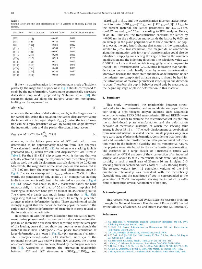
If the γ-ε transformation is the predominant mode of incipientplasticity, the magnitude of pop-ins in Fig. 3 should correspond tostrain by the transformation. According to geometrically necessarydislocation loop model proposed by Shibutani et al. [30], theexcursion depth Δh along the Burgers vector for monopartialfaulting can be expressed as
Δh¼ njbpj ð1Þ
where n is the number of dislocations, and bp is the Burgers vectorfor partial slip. Using this equation, the lattice displacement alongthe indentation axis (pop-in depth, dpop-in) during the transforma-tion can be simply predicted as well by taking the angle betweenthe indentation axis and the partial direction, λ, into account:
dpop�in ¼ΔhU j cos λj ¼ naγffiffiffi
6p cos λjj ð2Þ
where aγ is the lattice parameter of FCC unit cell. aγ wasdetermined to be approximately 0.32 nm from TEM analyses.The calculated results of Eq. (2) for when one stacking fault isgenerated (n¼1), which we call unit displacement, are listed inTable 1. For the (111)[112] slip system, which is the one that wasactually activated during the experiment and theoretically favor-able as well, the unit displacement was calculated to be 0.082 nm.Meanwhile, the magnitude of the small pop-ins was measured as1.75–3.02 nm, from the experimental load–displacement curve inFig. 4. The values correspond to dpop-in when n¼21–37. In otherwords, the generation of only about 21–37 monopartial stackingfaults in a moment is sufficient to be detected as a pop-in in Fig. 4.Fig. 5(d) shows that about 15 thin ε-martensite bands are lyingmonopartially in a small area of 20 nm�20 nm, implying 2–3stacking faults for each band (with a total of 30–45 stacking faults).The cluster of ε bands was much larger than that in Fig. 5(d),suggesting that over 20 stacking faults could surely be generatedat once as plastic deformation begins. These experimental resultsstrongly suggest that the nanoindentation pop-in behavior in theearly stage of plastic deformation of austenite is closely related tothe formation of ε-martensite.
In connection with the above discussion that the lattice move-ment during phase transformation can introduce nanoindentationpop-in, an interesting question arises regarding why the later partof the loading curve did not show any pop-ins even though thematerial must have undergone ε-to-α0 phase transformation atlarge deformation, as shown in Fig. 5(a)–(c). Assuming α0-marten-site is body-centered cubic (BCC) structure, since c/a of thetetragonal structure was nearly 1 from TEM analyses, the processof ε-to-α0 transformation can be explained by the Burgers mechan-ism [31]. According to Burgers, the orientation relationshipbetween HCP and BCC structure is (0001)hcp//(110)bcc and
[1120]hcp//[111]bcc, and the transformation involves lattice move-ment to make [0001]hcp-[110]bcc and [1120]hcp-1/2[1 1 1]bcc. Inthe present material, the lattice parameters are aε¼0.23 nm,cε¼0.37 nm and aα0 ¼0.26 nm according to TEM analyses. Hence,in an HCP unit cell, the transformation contracts the lattice by�0.002 nm in the c direction and expands the lattice by 0.03 nmon average in the plane perpendicular to the c direction. For pop-in to occur, the only length change that matters is the contraction.Similar to γ-to-ε transformation, the magnitude of contractionalong the indentation axis for ε-to-α0 transformation could also becalculated simply by considering the angle between the contract-ing direction and the indenting direction. The calculated value was0.00068 nm for a unit cell, which is negligibly small compared tothat of γ-to-ε transformation (¼0.082 nm), indicating that nanoin-dentation pop-in could hardly occur by ε-to-α0 transformation.Moreover, because the stress state and mode of deformation underthe indenter are complicated at large strain, it should be hard forthe introduction of massive geometrical softening in one directionto occur. Therefore, the pop-in behavior could only be measured atthe beginning stage of plastic deformation in this material.
4. Summary
This study investigated the relationship between stress-induced γ to ε transformation and nanoindentation pop-in beha-vior using a high-nitrogen alloyed stainless steel. Sequentialexperiments using EBSD, SPM, nanoindenter, FIB and HRTEM werecarried out in order to examine the micromechanical insight intothe strain-induced phase transformation and the deformationbehavior of metastable austenite, of which the stacking faultenergy is about 15 mJ m�2. The load–displacement curve obtainedfrom nanoindentation revealed several small pop-ins only in avery early stage of plastic deformation. Considering that the strain-induced ε-martensite transformation is the predominant deforma-tion mode in the incipient plasticity and its monopartial nature,the pop-ins were attributed to the ε-martensite transformation.The existence of a large cluster of ε-martensite bands wasconfirmed by HRTEM analyses of the cross-section of an indentedsample, and about 15 thin ε-martensite bands were lying mono-partially in such a small area of 20 nm�20 nm, implying 2–3stacking faults for each band (with a total of 30–45 stacking faults).The selected variant from 12 equivalent variants of the S–Norientation relationship was coincident with the theoreticallyfavorable one, and the magnitude of pop-in corresponded to thegeneration of 21–37 monopartial stacking faults, which is suffi-cient to introduce several nanometers of pop-ins.
Acknowledgment
This research was supported by Basic Science Research Programthrough the National Research Foundation of Korea (NRF) fundedby the Ministry of Science, ICT and Future Planning (2013008806).
References
[1] R.E. Reed-Hill, R. Abbaschian, Physical Metallurgy Principles, 3rd ed., PWSPublishing Company, Boston, 1994.
[2] D. Hull, D.J. Bacon, Introduction to Dislocations, 4th ed., Butterworth-Heinemann, Oxford, 2004.
[3] D.N. Lee, Strength of Materials, Munundang, Seoul, 2006.[4] K.-T. Park, K.-G. Jin, S.H. Han, S.W. Hwang, K. Choi, C.S. Lee, Mater. Sci. Eng. A
527 (2010) 3651–3661.[5] R.E. Schramm, R.P. Reed, Metall. Trans. A 6A (1975) 1345–1351.[6] L. Vitos, J.-O. Nilsson, B. Johansson, Acta Mater. 54 (2006) 3821–3826.[7] T.-H. Lee, E. Shin, C.-S. Oh, H.-Y. Ha, S.-J. Kim, Acta Mater. 58 (2010) 3173–3186.[8] A. Sato, E. Chishima, K. Soma, T. Mori, Acta Metall. 30 (1982) 1177–1183.[9] Z. Nishiyama, Martensitic Transformation, Academic Press, New York, 1978.
Table 1Schmid factor and the unit displacement for 12 variants of Shockley partial slipsystem.
Slip plane Partial direction Schmid factor Unit displacement (nm)
(111) [112] �0.483 0.082(111) [121] 0.324 0.055
(111) [211] 0.158 0.027
(111) [112] 0.384 0.112
(111) [121] �0.090 0.026
(111) [211] 0.294 0.086
(111) [112] 0.315 0.122
(111) [121] 0.121 0.047
(111) [211] 0.194 0.075
(111) [112] 0.464 0.093
(111) [121] 0.381 0.076
(111) [211] �0.083 0.017
T.-H. Ahn et al. / Materials Science & Engineering A 598 (2014) 56–6160

[10] J.H. Yang, C.M. Wayman, Mater. Charact. 28 (1992) 23–35.[11] N. Bergeon, G. Guenin, C. Esnouf, Mater. Sci. Eng. A 238 (1997) 309–316.[12] N. Bergeon, S. Kajiwara, T. Kikuchi, Acta Mater. 48 (2000) 4053–4064.[13] A. Sato, E. Chishima, Y. Yamaji, T. Mori, Acta Metall. 32 (1984) 539–547.[14] J.L. Putaux, J.P. Chevalier, Acta Mater. 44 (1996) 1701–1716.[15] T.-H. Ahn, C.-S. Oh, D.H. Kim, K.H. Oh, H. Bei, E.P. George, H.N. Han, Scr. Mater.
63 (2010) 540–543.[16] T. Ohmura, K. Tsuzaki, J. Mater. Sci. 42 (2007) 1728–1732.[17] H. Bei, Y.F. Gao, S. Shim, E.P. George, G.M. Pharr, Phys. Rev. B 77 (2008) 060103(R).[18] T.-H. Ahn, C.-S. Oh, K. Lee, E.P. George, Heung Nam Han, J. Mater. Res. 27 (2012)
39–44.[19] R.D.K. Misra, Z. Zhang, Z. Jia, P.K.C. Venkat Surya, M.C. Somani, L.P. Karjalainen,
Mater. Sci. Eng. A 528 (2011) 6958–6963.[20] K. Sekido, T. Ohmura, T. Sawaguchi, M. Koyama, H.W. Park, K. Tsuzaki, Scr.
Mater. 65 (2011) 942–945.
[21] J.Y. Choi, J.H. Ji, S.W. Hwang, K.-T. Park, Mater. Sci. Eng. A 535 (2012) 32–39.[22] K.L. Johnson, Contact Mechanics, Cambridge University Press, Cambridge,
1985.[23] A. Oila, S.J. Bull, Comput. Mater. Sci. 45 (2009) 235–239.[24] R.W.K. Honeycombe, Plastic Deformation of Metals, 2nd ed., Edward Arnold,
London, 1984.[25] A. Gouldstone, J.-J. Koh, K.-Y. Zeng, A.E. Giannakopoulos, S. Suresh, Acta Mater.
48 (2000) 2277–2295.[26] H. Bei, Z.P. Lu, E.P. George, Phys. Rev. Lett. 93 (2004) 125504.[27] H. Bei, E.P. George, J.L. Hay, G.M. Pharr, Phys. Rev. Lett. 95 (2005) 045501.[28] S. Shim, H. Bei, E.P. George, G.M. Pharr, Scr. Mater. 59 (2008) 1095–1098.[29] E. Schmid, W. Boas, Kristalplastizitat, Springer and Hughes, Berlin and London,
1950.[30] Y. Shibutani, A. Koyama, J. Mater. Res. 19 (2004) 183–188.[31] W.G. Burgers, Physica 1 (1934) 561–586.
T.-H. Ahn et al. / Materials Science & Engineering A 598 (2014) 56–61 61


![Department of Materials Science and Engineering, Drexel ...homes.nano.aau.dk/fp/self-assembling/lecture notes... · ciency of drugs and minimize toxic side effects [6]. The early](https://static.fdocument.org/doc/165x107/5f3ec29c3e51ff26a401cc49/department-of-materials-science-and-engineering-drexel-homesnanoaaudkfpself-assemblinglecture.jpg)