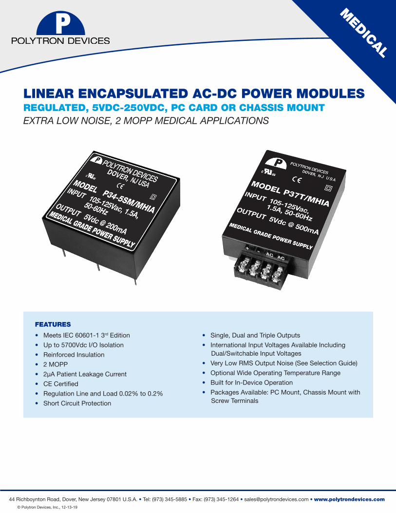
LINEAR ENCAPSULATED AC-DC POWER MODULES - Polytron Devices · Richboynton Road, Dover, New ersey 00...
11
DATA SHEET 44 Richboynton Road, Dover, New Jersey 07801 U.S.A. • Tel: (973) 345-5885 • Fax: (973) 345-1264 • [email protected] • www.polytrondevices.com © Polytron Devices, Inc., 12-13-19 FEATURES • Meets IEC 60601-1 3 rd Edition • Up to 5700Vdc I/O Isolation • Reinforced Insulation • 2 MOPP • 2μA Patient Leakage Current • CE Certified • Regulation Line and Load 0.02% to 0.2% • Short Circuit Protection • Single, Dual and Triple Outputs • International Input Voltages Available Including Dual/Switchable Input Voltages • Very Low RMS Output Noise (See Selection Guide) • Optional Wide Operating Temperature Range • Built for In-Device Operation • Packages Available: PC Mount, Chassis Mount with Screw Terminals LINEAR ENCAPSULATED AC-DC POWER MODULES REGULATED, 5VDC-250VDC, PC CARD OR CHASSIS MOUNT EXTRA LOW NOISE, 2 MOPP MEDICAL APPLICATIONS MEDICAL
Transcript of LINEAR ENCAPSULATED AC-DC POWER MODULES - Polytron Devices · Richboynton Road, Dover, New ersey 00...
DATA SHEET
44 Richboynton Road, Dover, New Jersey 07801 U.S.A. • Tel: (973) 345-5885 • Fax: (973) 345-1264 • [email protected] • www.polytrondevices.com © Polytron Devices, Inc., 12-13-19
FEATURES
• Meets IEC 60601-1 3rd Edition
• Up to 5700Vdc I/O Isolation
• Reinforced Insulation
• 2 MOPP
• 2μA Patient Leakage Current
• CE Certified
• Regulation Line and Load 0.02% to 0.2%
• Short Circuit Protection
• Single, Dual and Triple Outputs
• International Input Voltages Available Including Dual/Switchable Input Voltages
• Very Low RMS Output Noise (See Selection Guide)
• Optional Wide Operating Temperature Range
• Built for In-Device Operation
• Packages Available: PC Mount, Chassis Mount with Screw Terminals
LINEAR ENCAPSULATED AC-DC POWER MODULESREGULATED, 5VDC-250VDC, PC CARD OR CHASSIS MOUNTEXTRA LOW NOISE, 2 MOPP MEDICAL APPLICATIONS
MEDICAL
DATA SHEET
44 Richboynton Road, Dover, New Jersey 07801 U.S.A. • Tel: (973) 345-5885 • Fax: (973) 345-1264 • [email protected] • www.polytrondevices.com © Polytron Devices, Inc., 12-13-19
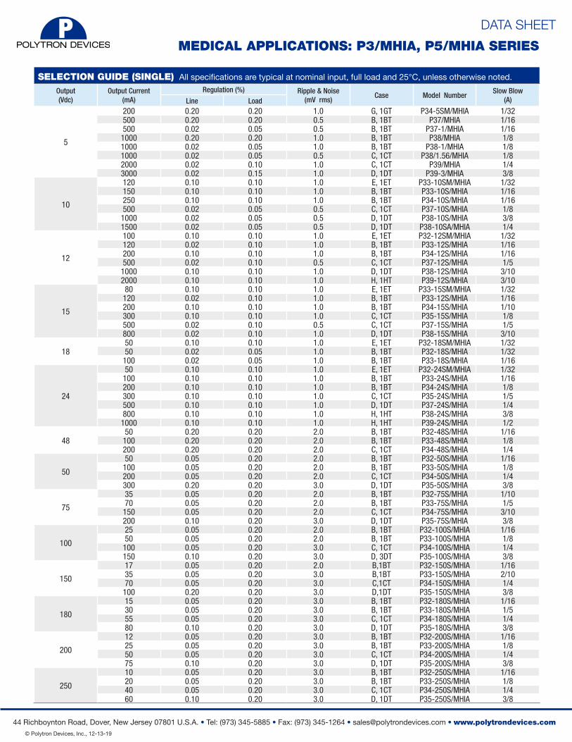
SELECTION GUIDE (SINGLE) All specifications are typical at nominal input, full load and 25°C, unless otherwise noted.Output (Vdc)
Output Current (mA)
Regulation (%) Ripple & Noise(mV rms)
Case Model NumberSlow Blow
(A) Line Load
5
200 0.20 0.20 1.0 G, 1GT P34-5SM/MHIA 1/32500 0.20 0.20 0.5 B, 1BT P37/MHIA 1/16500 0.02 0.05 0.5 B, 1BT P37-1/MHIA 1/16
1000 0.20 0.20 1.0 B, 1BT P38/MHIA 1/81000 0.02 0.05 1.0 B, 1BT P38-1/MHIA 1/81000 0.02 0.05 0.5 C, 1CT P38/1.56/MHIA 1/82000 0.02 0.10 1.0 C, 1CT P39/MHIA 1/43000 0.02 0.15 1.0 D, 1DT P39-3/MHIA 3/8
10
120 0.10 0.10 1.0 E, 1ET P33-10SM/MHIA 1/32150 0.10 0.10 1.0 B, 1BT P33-10S/MHIA 1/16250 0.10 0.10 1.0 B, 1BT P34-10S/MHIA 1/16500 0.02 0.05 0.5 C, 1CT P37-10S/MHIA 1/81000 0.02 0.05 0.5 D, 1DT P38-10S/MHIA 3/81500 0.02 0.05 0.5 D, 1DT P38-10SA/MHIA 1/4
12
100 0.10 0.10 1.0 E, 1ET P32-12SM/MHIA 1/32120 0.02 0.10 1.0 B, 1BT P33-12S/MHIA 1/16200 0.10 0.10 1.0 B, 1BT P34-12S/MHIA 1/16500 0.02 0.10 0.5 C, 1CT P37-12S/MHIA 1/51000 0.10 0.10 1.0 D, 1DT P38-12S/MHIA 3/102000 0.10 0.10 1.0 H, 1HT P39-12S/MHIA 3/10
15
80 0.10 0.10 1.0 E, 1ET P33-15SM/MHIA 1/32120 0.02 0.10 1.0 B, 1BT P33-12S/MHIA 1/16200 0.10 0.10 1.0 B, 1BT P34-15S/MHIA 1/10300 0.10 0.10 1.0 C, 1CT P35-15S/MHIA 1/8500 0.02 0.10 0.5 C, 1CT P37-15S/MHIA 1/5800 0.02 0.10 1.0 D, 1DT P38-15S/MHIA 3/10
1850 0.10 0.10 1.0 E, 1ET P32-18SM/MHIA 1/3250 0.02 0.05 1.0 B, 1BT P32-18S/MHIA 1/32
100 0.02 0.05 1.0 B, 1BT P33-18S/MHIA 1/16
24
50 0.10 0.10 1.0 E, 1ET P32-24SM/MHIA 1/32100 0.10 0.10 1.0 B, 1BT P33-24S/MHIA 1/16200 0.10 0.10 1.0 B, 1BT P34-24S/MHIA 1/8300 0.10 0.10 1.0 C, 1CT P35-24S/MHIA 1/5500 0.10 0.10 1.0 D, 1DT P37-24S/MHIA 1/4800 0.10 0.10 1.0 H, 1HT P38-24S/MHIA 3/81000 0.10 0.10 1.0 H, 1HT P39-24S/MHIA 1/2
4850 0.20 0.20 2.0 B, 1BT P32-48S/MHIA 1/16100 0.20 0.20 2.0 B, 1BT P33-48S/MHIA 1/8200 0.20 0.20 2.0 C, 1CT P34-48S/MHIA 1/4
50
50 0.05 0.20 2.0 B, 1BT P32-50S/MHIA 1/16100 0.05 0.20 2.0 B, 1BT P33-50S/MHIA 1/8200 0.05 0.20 2.0 C, 1CT P34-50S/MHIA 1/4300 0.20 0.20 3.0 D, 1DT P35-50S/MHIA 3/8
75
35 0.05 0.20 2.0 B, 1BT P32-75S/MHIA 1/1070 0.05 0.20 2.0 B, 1BT P33-75S/MHIA 1/5
150 0.05 0.20 2.0 C, 1CT P34-75S/MHIA 3/10200 0.10 0.20 3.0 D, 1DT P35-75S/MHIA 3/8
100
25 0.05 0.20 2.0 B, 1BT P32-100S/MHIA 1/1650 0.05 0.20 2.0 B, 1BT P33-100S/MHIA 1/8
100 0.05 0.20 3.0 C, 1CT P34-100S/MHIA 1/4150 0.10 0.20 3.0 D, 3DT P35-100S/MHIA 3/8
150
17 0.05 0.20 2.0 B,1BT P32-150S/MHIA 1/1635 0.05 0.20 3.0 B,1BT P33-150S/MHIA 2/1070 0.05 0.20 3.0 C,1CT P34-150S/MHIA 1/4
100 0.20 0.20 3.0 D,1DT P35-150S/MHIA 3/8
180
15 0.05 0.20 3.0 B, 1BT P32-180S/MHIA 1/1630 0.05 0.20 3.0 B, 1BT P33-180S/MHIA 1/555 0.05 0.20 3.0 C, 1CT P34-180S/MHIA 1/480 0.10 0.20 3.0 D, 1DT P35-180S/MHIA 3/8
200
12 0.05 0.20 3.0 B, 1BT P32-200S/MHIA 1/1625 0.05 0.20 3.0 B, 1BT P33-200S/MHIA 1/850 0.05 0.20 3.0 C, 1CT P34-200S/MHIA 1/475 0.10 0.20 3.0 D, 1DT P35-200S/MHIA 3/8
250
10 0.05 0.20 3.0 B, 1BT P32-250S/MHIA 1/1620 0.05 0.20 3.0 B, 1BT P33-250S/MHIA 1/840 0.05 0.20 3.0 C, 1CT P34-250S/MHIA 1/460 0.10 0.20 3.0 D, 1DT P35-250S/MHIA 3/8
MEDICAL APPLICATIONS: P3/MHIA, P5/MHIA SERIES
DATA SHEET
44 Richboynton Road, Dover, New Jersey 07801 U.S.A. • Tel: (973) 345-5885 • Fax: (973) 345-1264 • [email protected] • www.polytrondevices.com © Polytron Devices, Inc., 12-13-19
MEDICAL APPLICATIONS: P3/MHIA, P5/MHIA SERIES
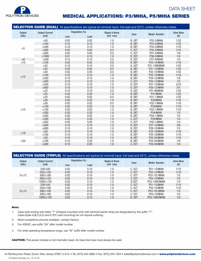
SELECTION GUIDE (DUAL) All specifications are typical at nominal input, full load and 25°C, unless otherwise noted.
Output (Vdc)
Output Current (mA)
Regulation (%) Ripple & Noise(mV rms)
Case Model NumberSlow Blow
(A) Line Load
±5
±50 0.02 0.02 1.0 B, 2BT P32-5/MHIA 1/32±100 0.10 0.10 1.0 B, 2BT P33-5/MHIA 1/32±200 0.10 0.10 1.0 B, 2BT P34-5/MHIA 1/16±300 0.02 0.05 0.5 C, 2CT P35-5/MHIA 1/10±500 0.02 0.05 0.5 C, 2CT P37-5/MHIA 1/8
±1000 0.01 0.10 1.0 D, 2DT P38-5/MHIA 1/4±8 ±5 ±500 00 0.10 0.10 2.0 D, 2DT P37-8/MHIA 1/5
±10 ±100 0.02 0.05 2.0 B, 2BT P33-10/MHIA 1/16
±12
±25 0.10 0.10 2.0 G, 2GT P31-12M/MHIA 1/32±25 0.02 0.05 0.5 B, 2BT P31-12/MHIA 1/32±50 0.02 0.05 0.5 B, 2BT P32-12/MHIA 1/32
±100 0.10 0.10 1.0 B, 2BT P33-12/MHIA 1/16±200 0.10 0.10 1.0 B, 2BT P34-12/MHIA 1/8±300 0.10 0.10 1.0 C, 2CT P35-12/MHIA 1/5±500 0.10 0.10 1.0 D, 2DT P37-12/MHIA 3/10±800 0.10 0.10 1.0 D, 2DT P38-12/MHIA 2/5
±15
±25 0.10 0.10 2.0 G, 2GT P31-M/MHIA 1/32±25 0.20 0.20 1.0 B, 2BT P31/MHIA 1/32±25 0.02 0.02 0.5 B, 2BT P31-1/MHIA 1/32±50 0.20 0.20 1.0 B, 2BT P32/MHIA 1/16±50 0.02 0.02 0.5 B, 2BT P32-1/MHIA 1/16
±100 0.20 0.20 1.0 B, 2BT P33/MHIA 1/10±100 0.02 0.02 1.0 B, 2BT P33-1/MHIA 1/10±200 0.20 0.20 1.0 B, 2BT P34/MHIA 1/5±200 0.02 0.05 1.0 B, 2BT P34-1/MHIA 1/5±350 0.20 0.20 1.0 C, 2CT P35/MHIA 1/4±350 0.02 0.05 1.0 C, 2CT P35-1/MHIA 1/4±500 0.10 0.10 1.0 D, 2DT P37-15/MHIA 3/8±800 0.10 0.10 1.0 D, 2DT P38-15/MHIA 1/2
±18 ±50 0.10 0.10 1.0 B, 2BT P32-18/MHIA 1/16±100 0.10 0.10 1.0 B, 2BT P33-18/MHIA 1/10
±24±50 0.10 0.10 1.0 B, 2BT P32-24/MHIA 1/16
±100 0.10 0.20 1.0 B, 2BT P33-24/MHIA 1/8±200 0.10 0.20 1.0 C, 2CT P34-24/MHIA 1/4
SELECTION GUIDE (TRIPLE) All specifications are typical at nominal input, full load and 25°C, unless otherwise noted.
Output (Vdc)
Output Current (mA)
Regulation (%) Ripple & Noise(mV rms)
Case Model NumberSlow Blow
(A) Line Load
5/±12
250/±60 0.02 0.10 1.0 C, 3CT P51-12/MHIA 1/10250/±120 0.02 0.10 1.0 C, 3CT P52-12/MHIA 1/10300/±180 0.02 0.10 1.0 C, 3CT P53-12L/MHIA 1/5500/±120 0.02 0.10 1.0 C, 3CT P53-12/MHIA 1/5
1000/±150 0.02 0.10 1.0 D,3DT P53-1280/MHIA 1/4
5/±15
250/±50 0.02 0.10 1.0 C, 3CT P51-15/MHIA 1/10250/±100 0.02 0.10 1.0 C, 3CT P52-15/MHIA 1/10300/±150 0.02 0.10 1.0 C, 3CT P53-15L/MHIA 1/5500/±100 0.02 0.10 1.0 C, 3CT P53-15/MHIA 1/5
1000/±150 0.02 0.10 1.0 D, 3DT P53-1580/MHIA 1/4
Note:
1. Case style ending with letter “T” (Chassis mounted units with terminal barrier strip) are designated by the suffix “T”. Case styles A,B,C,D,G and E (PC card mounting) do not require suffixing.
2. Most competitors pinouts available--contact factory.
3. For 400HZ, use suffix “04” after model number.
4. For wide operating temperature range, use “W” suffix after model number.
CAUTION: This power module is not internally fused. An input line fuse must always be used.
DATA SHEET
44 Richboynton Road, Dover, New Jersey 07801 U.S.A. • Tel: (973) 345-5885 • Fax: (973) 345-1264 • [email protected] • www.polytrondevices.com © Polytron Devices, Inc., 12-13-19
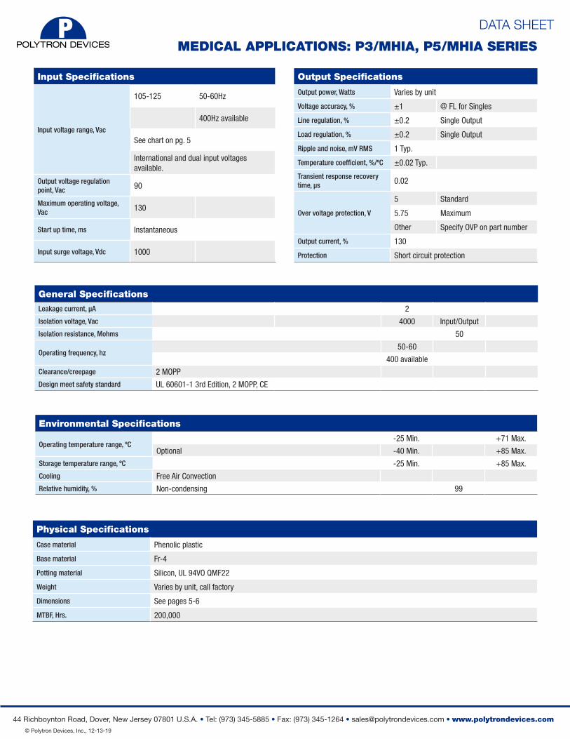
Input Specifications
Input voltage range, Vac
105-125 50-60Hz
400Hz available
See chart on pg. 5
International and dual input voltages available.
Output voltage regulation point, Vac 90
Maximum operating voltage, Vac 130
Start up time, ms Instantaneous
Input surge voltage, Vdc 1000
Output Specifications
Output power, Watts Varies by unit
Voltage accuracy, % ±1 @ FL for Singles
Line regulation, % ±0.2 Single Output
Load regulation, % ±0.2 Single Output
Ripple and noise, mV RMS 1 Typ.
Temperature coefficient, %/ºC ±0.02 Typ.
Transient response recovery time, μs 0.02
Over voltage protection, V
5 Standard
5.75 Maximum
Other Specify OVP on part number
Output current, % 130
Protection Short circuit protection
Environmental Specifications
Operating temperature range, ºC-25 Min. +71 Max.
Optional -40 Min. +85 Max.
Storage temperature range, ºC -25 Min. +85 Max.
Cooling Free Air Convection
Relative humidity, % Non-condensing 99
General Specifications
Leakage current, μA 2
Isolation voltage, Vac 4000 Input/Output
Isolation resistance, Mohms 50
Operating frequency, hz50-60
400 available
Clearance/creepage 2 MOPP
Design meet safety standard UL 60601-1 3rd Edition, 2 MOPP, CE
MEDICAL APPLICATIONS: P3/MHIA, P5/MHIA SERIES
Physical Specifications
Case material Phenolic plastic
Base material Fr-4
Potting material Silicon, UL 94VO QMF22
Weight Varies by unit, call factory
Dimensions See pages 5-6
MTBF, Hrs. 200,000
DATA SHEET
44 Richboynton Road, Dover, New Jersey 07801 U.S.A. • Tel: (973) 345-5885 • Fax: (973) 345-1264 • [email protected] • www.polytrondevices.com © Polytron Devices, Inc., 12-13-19
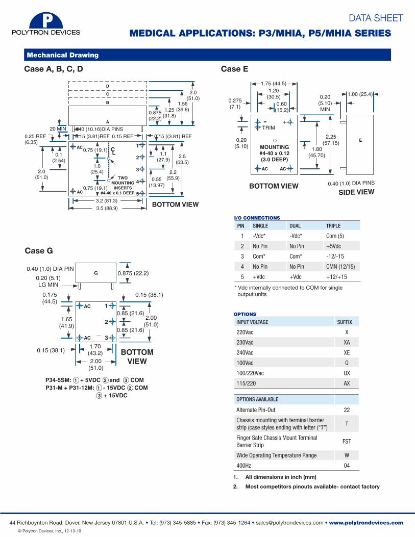
Mechanical Drawing
Case A, B, C, D
BOTTOM VIEW
2.0 (51.0)
2.5 (63.5)
0.1(2.54)
3.2 (81.3)
2.0(51.0)
0.15 ((3.81) REF0.15 REF
3.5 (88.9)
0.75 (19.1)
0.75 (19.1)
1.0(25.4)
0.15 (3.81)REF0.25 REF(6.35)
20 MIN .040 (10.16)DIA PINS
1.1(27.9)
0.55(13.97)
2.2(55.9)
1.56(39.6)1.25
(31.8)0.875(22.2)
CASE A, B, C, D
CL
TWOMOUNTING
INSERTS#4-40 x 0.1 DEEP
AC 1
2
3
4
5AC
A
B
C
D
SIDE VIEWBOTTOM VIEW
All Dimensions are in inches (mm)
1.75 (44.5)
0.20 (5.10)
2.25(57.15)
1.80(45.70)
1.00 (25.4)0.20(5.10)MIN
0.275(7.1)
0.40 (1.0) DIA PINS
1.20(30.5)
0.60(15.2)
CASE E
MOUNTING#4-40 x 0.12(3.0 DEEP)
AC
+
AC
E
-TRIM
Case E
MEDICAL APPLICATIONS: P3/MHIA, P5/MHIA SERIES
BOTTOMVIEW
0.875 (22.2)
0.175(44.5)
0.15 (38.1)1.70
(43.2)
0.15 (38.1)
0.85 (21.6)
0.85 (21.6)
1.65(41.9)
2.00(51.0)
2.00(51.0)
0.20 (5.1)LG MIN
0.40 (1.0) DIA PIN
CASE G
1
2
3AC
AC
G
P34-5SM: 1 + 5VDC 2 and 3 COMP31-M + P31-12M: 1 - 15VDC 2 COM 3 + 15VDC
Case G
I/O CONNECTIONS
PIN SINGLE DUAL TRIPLE
1 -Vdc* -Vdc* Com (5)
2 No Pin No Pin +5Vdc
3 Com* Com* -12/-15
4 No Pin No Pin CMN (12/15)
5 +Vdc +Vdc +12/+15
* Vdc internally connected to COM for single output units
1. All dimensions in inch (mm)
2. Most competitors pinouts available- contact factory
INPUT VOLTAGE SUFFIX
220Vac X
230Vac XA
240Vac XE
100Vac Q
100/220Vac QX
115/220 AX
OPTIONS AVAILABLE
Alternate Pin-Out 22
Chassis mounting with terminal barrier strip (case styles ending with letter (“T”)
T
Finger Safe Chassis Mount Terminal Barrier Strip
FST
Wide Operating Temperature Range W
400Hz 04
OPTIONS
DATA SHEET
44 Richboynton Road, Dover, New Jersey 07801 U.S.A. • Tel: (973) 345-5885 • Fax: (973) 345-1264 • [email protected] • www.polytrondevices.com © Polytron Devices, Inc., 12-13-19
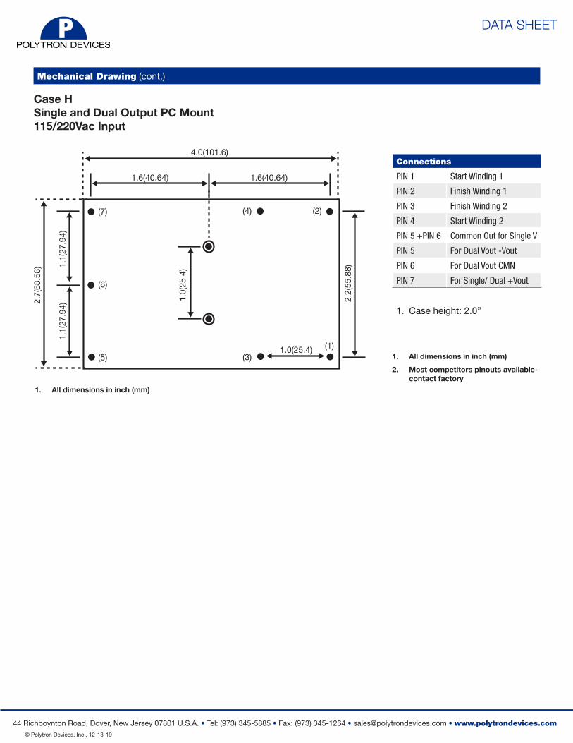
Mechanical Drawing (cont.)
1. All dimensions in inch (mm)
2. Most competitors pinouts available- contact factory
1. Case height: 2.0”
Connections
PIN 1 Start Winding 1
PIN 2 Finish Winding 1
PIN 3 Finish Winding 2
PIN 4 Start Winding 2
PIN 5 +PIN 6 Common Out for Single V
PIN 5 For Dual Vout -Vout
PIN 6 For Dual Vout CMN
PIN 7 For Single/ Dual +Vout
Case HSingle and Dual Output PC Mount115/220Vac Input
2.7(
68.5
8)
4.0(101.6)
1.1(
27.9
4)1.
1(27
.94)
1.0(
25.4
)
2.2(
55.8
8)(5)
(6)
(7)
(3)
(4)
(1)
(2)
1.6(40.64)
1.0(25.4)
1.6(40.64)
1. All dimensions in inch (mm)
DATA SHEET
44 Richboynton Road, Dover, New Jersey 07801 U.S.A. • Tel: (973) 345-5885 • Fax: (973) 345-1264 • [email protected] • www.polytrondevices.com © Polytron Devices, Inc., 12-13-19
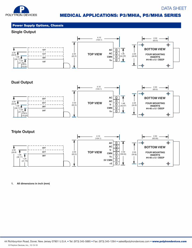
Power Supply Options, Chassis
Single Output
All Dimensions are in inches (mm)
CHASSIS MOUNTED UNITS
TOP VIEW
SINGLE OUTPUT MODELS
DUAL OUTPUT MODELS
TRIPLE OUTPUT MODELS
FOUR MOUNTINGINSERTS
#4-40 x 0.1 DEEP1AT
AC
AC
CMN
V+1BT
1CT
1DT
1.25(31.75)
2.50(63.5)
1.35(34.29)1.56
(39.11)
2.00(50.8)
TOP VIEW
AC
AC
V-
CMN
2.50(63.5)
1.68(42.67)
V+
TOP VIEW
AC
AC
V-
CMN2.50
(63.5)2.32
(58.93)
V+
5V CMN
+5
4.10(104.1)
BOTTOM VIEW2.00
(50.8)
2.50(63.5)
FOUR MOUNTINGINSERTS
#4-40 x 0.1 DEEP
BOTTOM VIEW
2.00(50.8)
2.50(63.5)
FOUR MOUNTINGINSERTS
#4-40 x 0.1 DEEP
BOTTOM VIEW
2.00(50.8)
2.50(63.05)
0.875(19.05)
2AT
2BT
2CT
2DT
3BT
3CT
3DT
1.25(31.75)
1.56(39.11)
2.00(50.8)
1.25(31.75)
1.56(39.11)
2.00(50.8)
0.875(19.05)
4.10(104.1)
4.10(104.1)
Dual Output
Triple Output
1. All dimensions in inch (mm)
MEDICAL APPLICATIONS: P3/MHIA, P5/MHIA SERIES
DATA SHEET
44 Richboynton Road, Dover, New Jersey 07801 U.S.A. • Tel: (973) 345-5885 • Fax: (973) 345-1264 • [email protected] • www.polytrondevices.com © Polytron Devices, Inc., 12-13-19
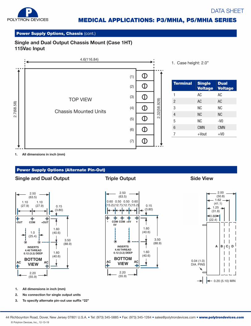
Power Supply Options (Alternate Pin-Out)
All Dimensions are in inches (mm)
SIDE VIEW
BOTTOMVIEW
1.62(41.1)
1.25(31.8)
0.88(22.4)
0.04 (1.0)DIA. PINS
0.20 (5.10) MIN
2.00(50.8)
2.50(63.5)
0.15(3.80)
0.50(12.7)
0.50(12.7)
0.60(15.2)
0.60(15.2)
1.60(40.6)
1.60(40.6)
2.20(55.9)
1.0(25.4)
3.50(88.9)
INSERTS4.40 THREAD
0.12 (3.2) DEEP
A
AC
COM5V
COM +5V +-
ACBOTTOM
VIEW
2.50(63.5)
0.15(3.80)
1.10(27.9)
1.10(27.9)
1.60(40.6)
1.60(40.6)
2.20(55.9)
3.50(88.9)
INSERTS4.40 THREAD
0.12 (3.2) DEEP
AC
COM +OUT-OUT
AC
B C D
ALTERNATE PIN-OUTTRIPLE OUTPUT MODELS
Note:* No connection for single output units* To specify alternate pin-out use suffix "22"
SINGLE & DUAL OUTPUT MODELSSingle and Dual Output
All Dimensions are in inches (mm)
SIDE VIEW
BOTTOMVIEW
1.62(41.1)
1.25(31.8)
0.88(22.4)
0.04 (1.0)DIA. PINS
0.20 (5.10) MIN
2.00(50.8)
2.50(63.5)
0.15(3.80)
0.50(12.7)
0.50(12.7)
0.60(15.2)
0.60(15.2)
1.60(40.6)
1.60(40.6)
2.20(55.9)
1.0(25.4)
3.50(88.9)
INSERTS4.40 THREAD
0.12 (3.2) DEEP
A
AC
COM5V
COM +5V +-
ACBOTTOM
VIEW
2.50(63.5)
0.15(3.80)
1.10(27.9)
1.10(27.9)
1.60(40.6)
1.60(40.6)
2.20(55.9)
3.50(88.9)
INSERTS4.40 THREAD
0.12 (3.2) DEEP
AC
COM +OUT-OUT
AC
B C D
ALTERNATE PIN-OUTTRIPLE OUTPUT MODELS
Note:* No connection for single output units* To specify alternate pin-out use suffix "22"
SINGLE & DUAL OUTPUT MODELS
Triple Output Side View
1. All dimensions in inch (mm)
2. No connection for single output units
3. To specify alternate pin-out use suffix “22”
MEDICAL APPLICATIONS: P3/MHIA, P5/MHIA SERIES
Single and Dual Output Chassis Mount (Case 1HT)115Vac Input
1. Case height: 2.0”
Terminal SingleVoltage
DualVoltage
1 AC AC
2 AC AC
3 NC NC
4 NC NC
5 NC -V0
6 CMN CMN
7 +Vout +V0
Power Supply Options, Chassis (cont.)
TOP VIEW
Chassis Mounted Units
4.6(116.84)
2.32
(58.
928)
2.7(
68.5
8)
(1)
(2)
(3)
(4)
(5)
(6)
(7)
1. All dimensions in inch (mm)
DATA SHEET
44 Richboynton Road, Dover, New Jersey 07801 U.S.A. • Tel: (973) 345-5885 • Fax: (973) 345-1264 • [email protected] • www.polytrondevices.com © Polytron Devices, Inc., 12-13-19
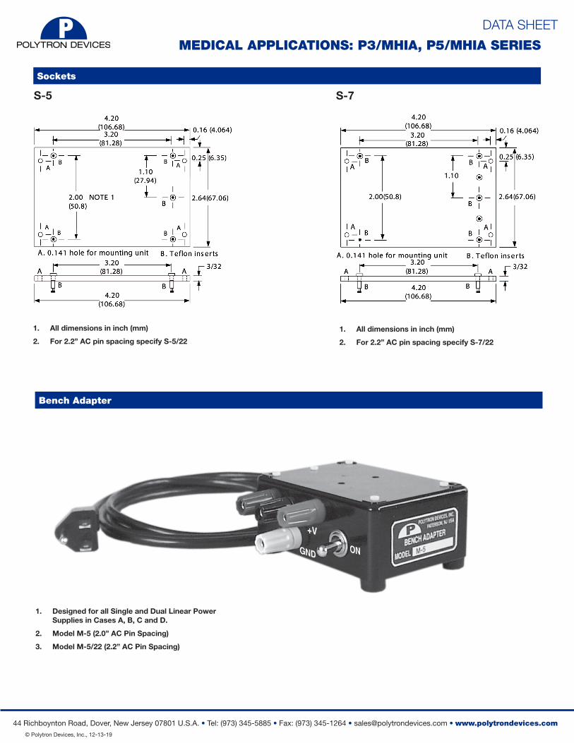
Bench Adapter
1. Designed for all Single and Dual Linear Power Supplies in Cases A, B, C and D.
2. Model M-5 (2.0” AC Pin Spacing)
3. Model M-5/22 (2.2” AC Pin Spacing)
MEDICAL APPLICATIONS: P3/MHIA, P5/MHIA SERIES
Sockets
1. All dimensions in inch (mm)
2. For 2.2” AC pin spacing specify S-7/22
S-5 S-7
1. All dimensions in inch (mm)
2. For 2.2” AC pin spacing specify S-5/22
DATA SHEET
44 Richboynton Road, Dover, New Jersey 07801 U.S.A. • Tel: (973) 345-5885 • Fax: (973) 345-1264 • [email protected] • www.polytrondevices.com © Polytron Devices, Inc., 12-13-19
Wiring Instructions for AC-DC Linear Power Modules with Dual/Switchable AC Input Voltages
MEDICAL APPLICATIONS: P3/MHIA, P5/MHIA SERIES
TOP VIEW
Chassis Mounted Units
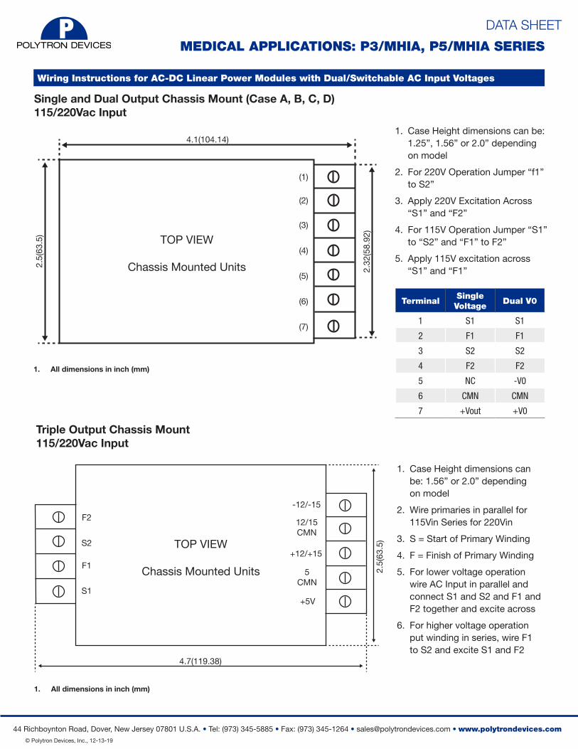
4.7(119.38)
-12/-15
12/15CMN
+12/+15
5CMN
+5V
2.5(
63.5
)
F2
S2
F1
S1
1. Case Height dimensions can be: 1.56” or 2.0” depending on model
2. Wire primaries in parallel for 115Vin Series for 220Vin
3. S = Start of Primary Winding
4. F = Finish of Primary Winding
5. For lower voltage operation wire AC Input in parallel and connect S1 and S2 and F1 and F2 together and excite across
6. For higher voltage operation put winding in series, wire F1 to S2 and excite S1 and F2
Triple Output Chassis Mount115/220Vac Input
Single and Dual Output Chassis Mount (Case A, B, C, D)115/220Vac Input
TOP VIEW
Chassis Mounted Units
4.1(104.14)
2.32
(58.
92)
2.5(
63.5
)
(1)
(2)
(3)
(4)
(5)
(6)
(7)
1. Case Height dimensions can be: 1.25”, 1.56” or 2.0” depending on model
2. For 220V Operation Jumper “f1” to S2”
3. Apply 220V Excitation Across “S1” and “F2”
4. For 115V Operation Jumper “S1” to “S2” and “F1” to F2”
5. Apply 115V excitation across “S1” and “F1”
TerminalSingle Voltage
Dual V0
1 S1 S1
2 F1 F1
3 S2 S2
4 F2 F2
5 NC -V0
6 CMN CMN
7 +Vout +V0
1. All dimensions in inch (mm)
1. All dimensions in inch (mm)
DATA SHEET
44 Richboynton Road, Dover, New Jersey 07801 U.S.A. • Tel: (973) 345-5885 • Fax: (973) 345-1264 • [email protected] • www.polytrondevices.com © Polytron Devices, Inc., 12-13-19
Wiring Instructions for AC-DC Linear Power Modules with Dual/Switchable AC Input Voltages (cont.)
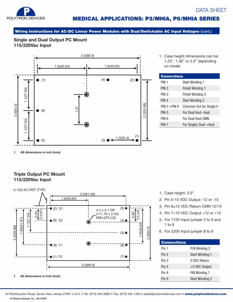
MEDICAL APPLICATIONS: P3/MHIA, P5/MHIA SERIES2.
5(63
.5)
3.5(88.9)
1.1(
27.9
4)1.
1(27
.94)
1.0”
2.2(
55.8
8)(5)
(6)
(7)
(3)
(4)
(1)
(2)
1.6(40.64)
1.0(25.4)
1. Case height dimensions can be: 1.25”, 1.56” or 2.0” depending on model
Connections
PIN 1 Start Winding 1
PIN 2 Finish Winding 1
PIN 3 Finish Winding 2
PIN 4 Start Winding 2
PIN 5 +PIN 6 Common Out for Single V
PIN 5 For Dual Vout -Vout
PIN 6 For Dual Vout CMN
PIN 7 For Single/ Dual +Vout
1.6(40.64)
Single and Dual Output PC Mount115/220Vac Input
Triple Output PC Mount115/220Vac Input
3.2(81.28)
2.2(
55.8
8)
1.6(40.64)
3.5(88.9)
(2) S1
(9) S2
(8) F1
(1) F2
(3)
(4)
(5)
(7)
(6)
1.65
(41.
91)
1.1(
27.9
4) 0.55
(1
3.97
)
0.60
(1
5.24
)1.
6(40
.64)
2.5(
63.5
)
0.15(3.81) REF (TYP)
4.4 x 0.1 DP (111.76 x 2.54)MIN (2PLCS)
1. Case height: 2.0”
2. Pin 5-15 VDC Output -12 or -15
3. Pin 6±15 VDC Return CMN 12/15
4. Pin 7+15 VDC Output +12 or +15
5. For 115V Input jumper 2 to 9 and 1 to 8
6. For 220V Input jumper 8 to 9
Connections
Pin 1 F/N Winding 2
Pin 2 Start Winding 1
Pin 3 5 VDC Return
Pin 4 +5 VDC Output
Pin 8 FIN Winding 1
Pin 9 Start Winding 2
1. All dimensions in inch (mm)
1. All dimensions in inch (mm)
© Polytron Devices, Inc., 3-21-2019