Compact Sealed lithium target for accelerator-driven BNCT ...
Upload
patricia-reedCategory
view
221download
0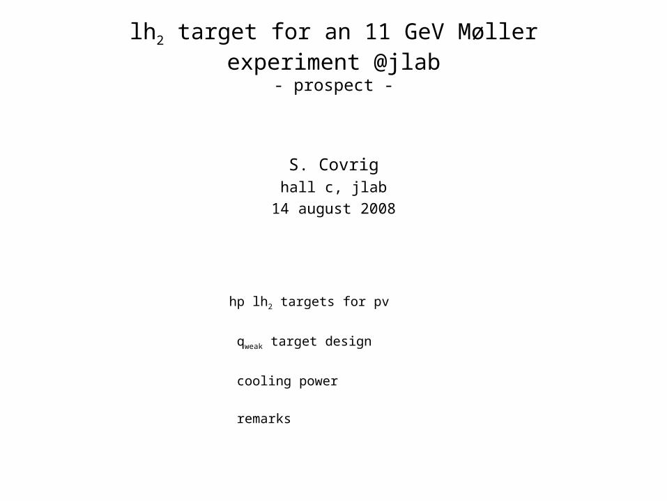
lh2 target for an 11 GeV Møller experiment @jlab- prospect -
S. Covrighall c, jlab
14 august 2008
hp lh2 targets for pv
qweak target design
cooling power
remarks
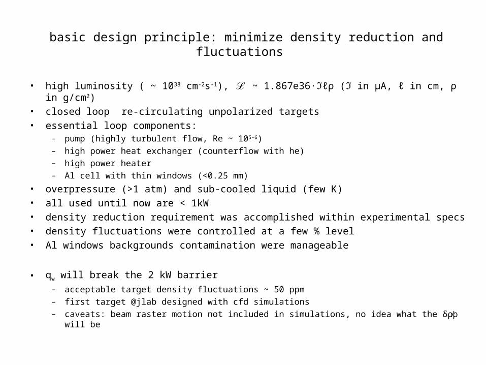
basic design principle: minimize density reduction and fluctuations
• high luminosity ( ~ 1038 cm-2s-1), ℒ ~ 1.867e36·ℑℓρ (ℑ in µA, ℓ in cm, ρ in g/cm2)• closed loop re-circulating unpolarized targets• essential loop components:
– pump (highly turbulent flow, Re ~ 105-6)– high power heat exchanger (counterflow with he)– high power heater – Al cell with thin windows (<0.25 mm)
• overpressure (>1 atm) and sub-cooled liquid (few K)• all used until now are < 1kW• density reduction requirement was accomplished within experimental specs• density fluctuations were controlled at a few % level• Al windows backgrounds contamination were manageable
• qw will break the 2 kW barrier– acceptable target density fluctuations ~ 50 ppm – first target @jlab designed with cfd simulations– caveats: beam raster motion not included in simulations, no idea what the δρ⁄ρ will be
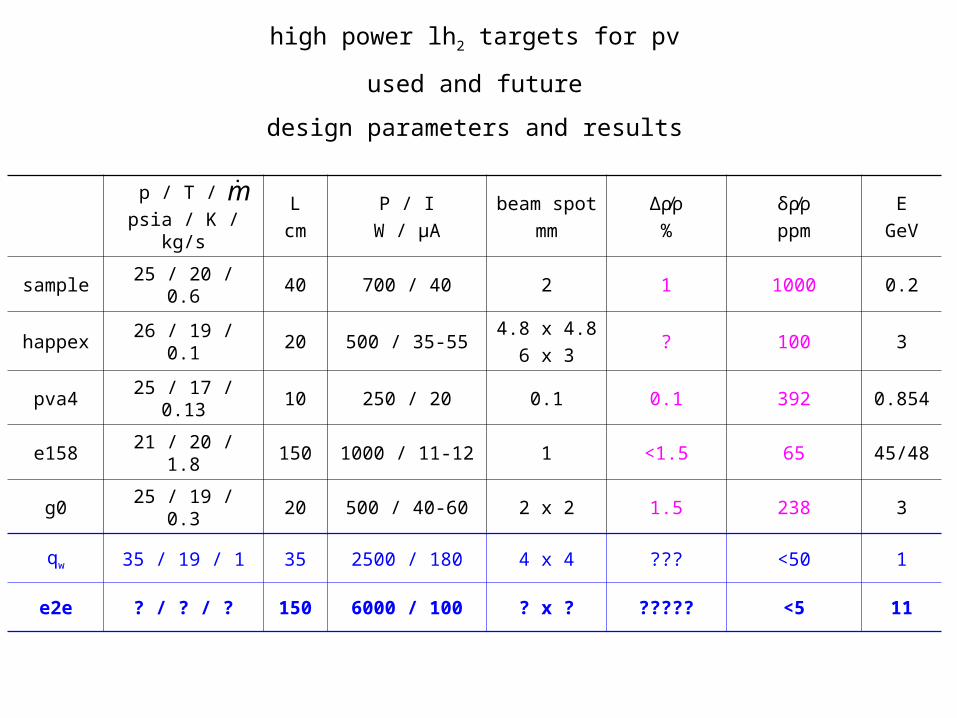
p / T / psia / K / kg/s
Lcm
P / IW / µA
beam spotmm
Δρ⁄ρ%
δρ⁄ρppm
EGeV
sample 25 / 20 / 0.6 40 700 / 40 2 1 1000 0.2
happex 26 / 19 / 0.1 20 500 / 35-554.8 x 4.8
6 x 3? 100 3
pva4 25 / 17 / 0.13 10 250 / 20 0.1 0.1 392 0.854
e158 21 / 20 / 1.8 150 1000 / 11-12 1 <1.5 65 45/48
g0 25 / 19 / 0.3 20 500 / 40-60 2 x 2 1.5 238 3
qw 35 / 19 / 1 35 2500 / 180 4 x 4 ??? <50 1
e2e ? / ? / ? 150 6000 / 100 ? x ? ????? <5 11
m
high power lh2 targets for pv
used and future
design parameters and results
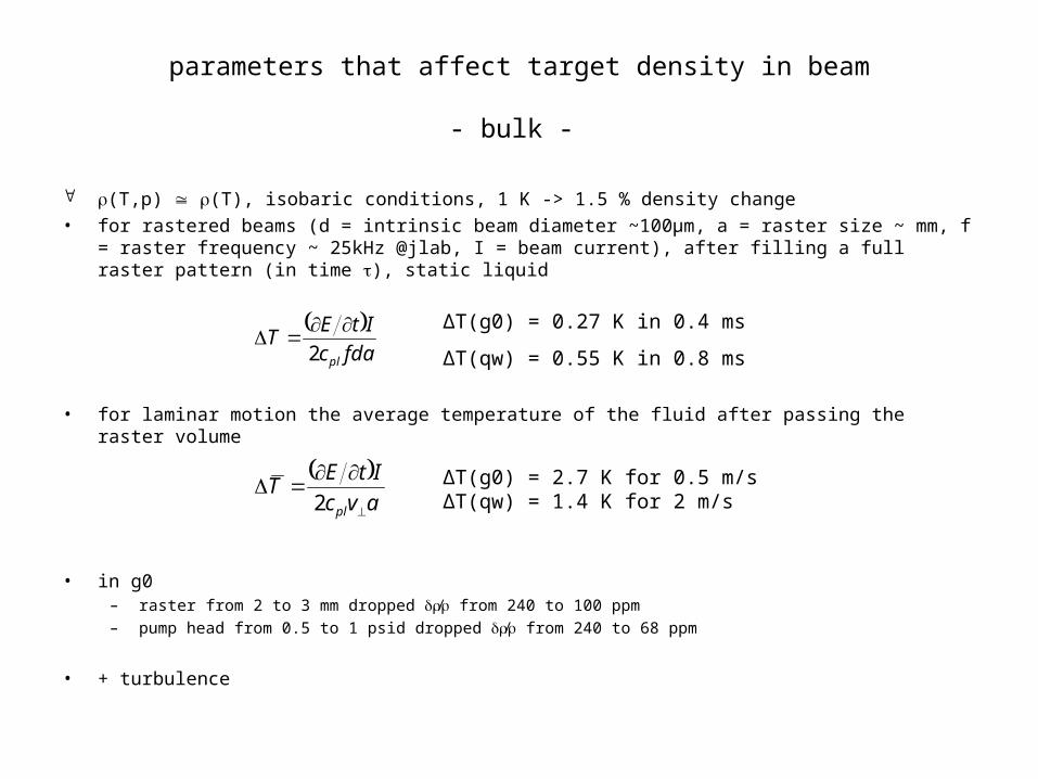
parameters that affect target density in beam
- bulk -
(T,p) (T), isobaric conditions, 1 K -> 1.5 % density change• for rastered beams (d = intrinsic beam diameter ~100µm, a = raster size ~ mm, f =
raster frequency ~ 25kHz @jlab, I = beam current), after filling a full raster pattern (in time ), static liquid
• for laminar motion the average temperature of the fluid after passing the raster volume
• in g0 – raster from 2 to 3 mm dropped ⁄ from 240 to 100 ppm– pump head from 0.5 to 1 psid dropped ⁄ from 240 to 68 ppm
• + turbulence
fdac
ItET
pl2
avc
ItET
pl
2
ΔT(g0) = 0.27 K in 0.4 ms
ΔT(qw) = 0.55 K in 0.8 ms
ΔT(g0) = 2.7 K for 0.5 m/sΔT(qw) = 1.4 K for 2 m/s
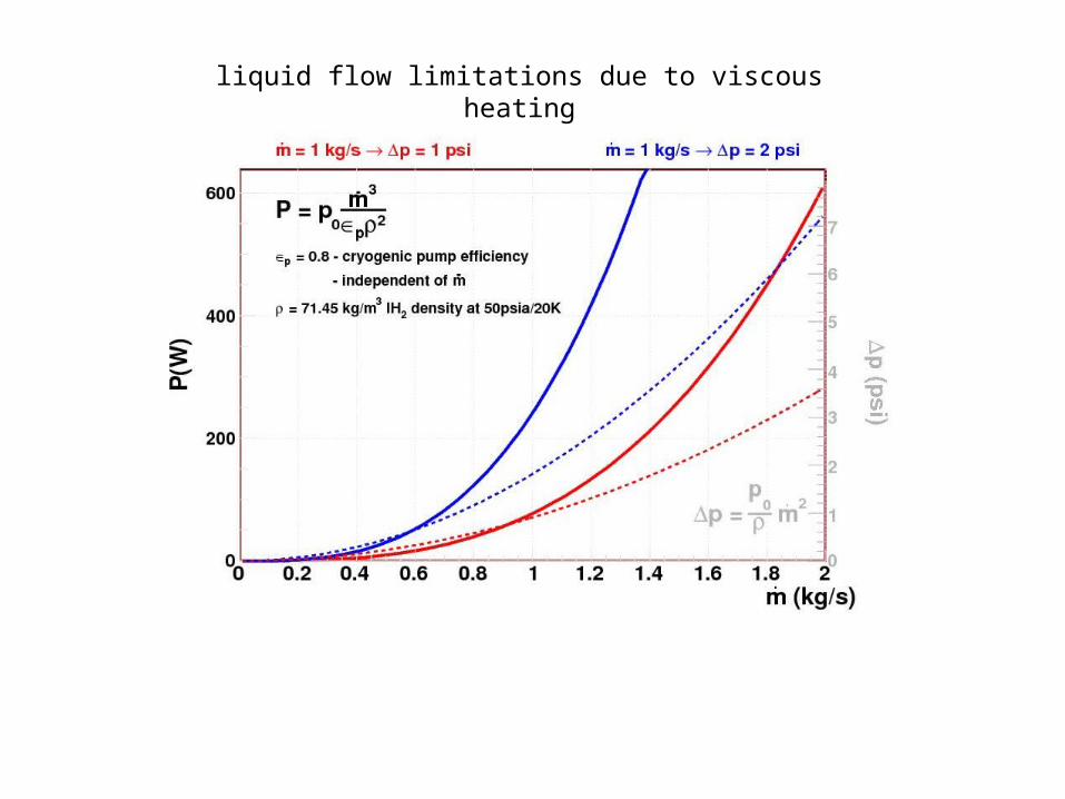
liquid flow limitations due to viscous heating
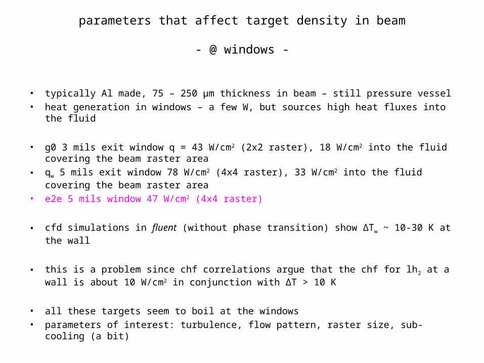
parameters that affect target density in beam
- @ windows -
• typically Al made, 75 – 250 µm thickness in beam – still pressure vessel• heat generation in windows – a few W, but sources high heat fluxes into the
fluid
• g0 3 mils exit window q = 43 W/cm2 (2x2 raster), 18 W/cm2 into the fluid covering the beam raster area
• qw 5 mils exit window 78 W/cm2 (4x4 raster), 33 W/cm2 into the fluid covering the beam raster area
• e2e 5 mils window 47 W/cm2 (4x4 raster)
• cfd simulations in fluent (without phase transition) show ΔTw ~ 10-30 K at the wall
• this is a problem since chf correlations argue that the chf for lh2 at a wall is about 10 W/cm2 in conjunction with ΔT > 10 K
• all these targets seem to boil at the windows• parameters of interest: turbulence, flow pattern, raster size, sub-cooling (a
bit)
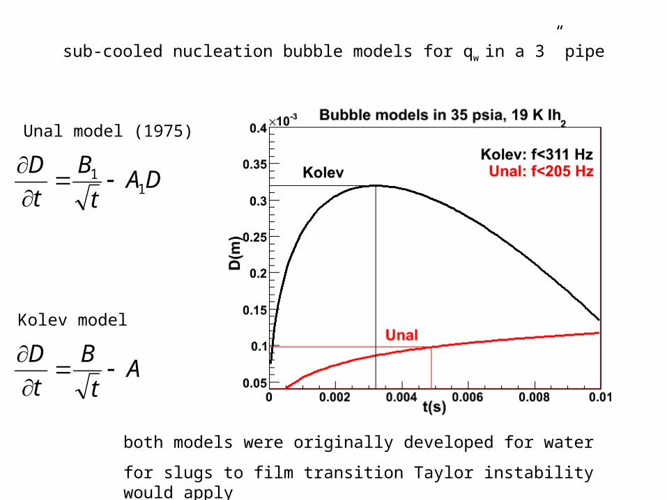
sub-cooled nucleation bubble models for qw in a 3” pipe
DAt
B
t
D1
1 Unal model (1975)
At
B
t
D
Kolev model
both models were originally developed for water
for slugs to film transition Taylor instability would apply
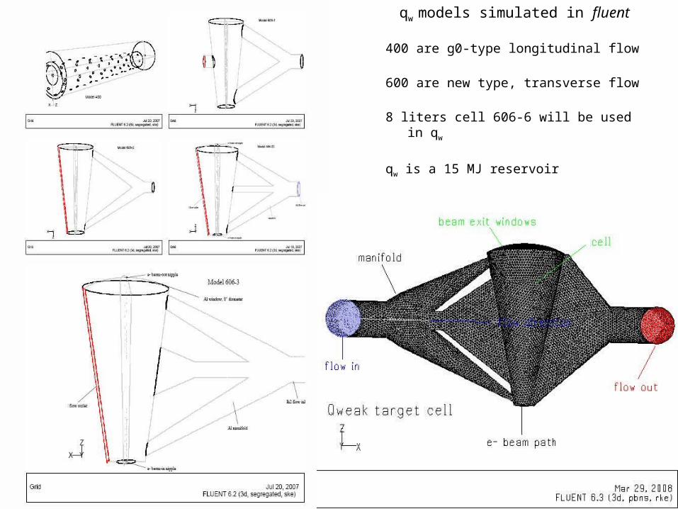
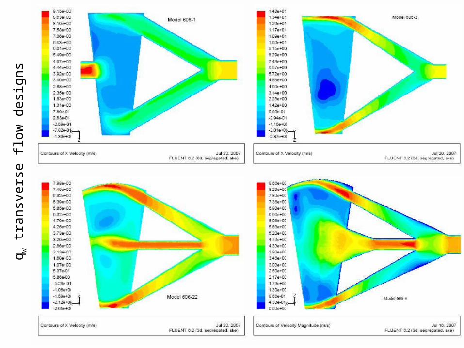
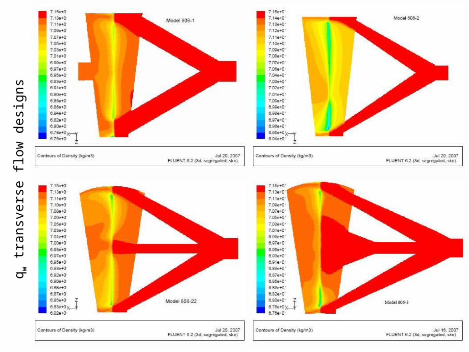
qw models simulated in fluent
400 are g0-type longitudinal flow
600 are new type, transverse flow
8 liters cell 606-6 will be used in qw
qw is a 15 MJ reservoir
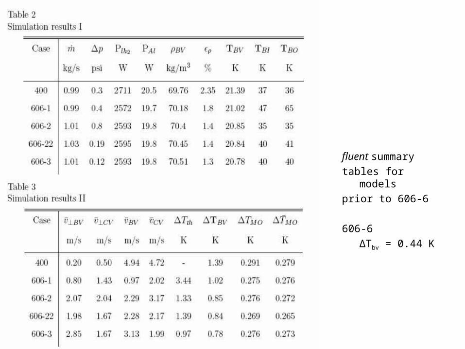
fluent summarytables for modelsprior to 606-6
606-6ΔTbv = 0.44 K
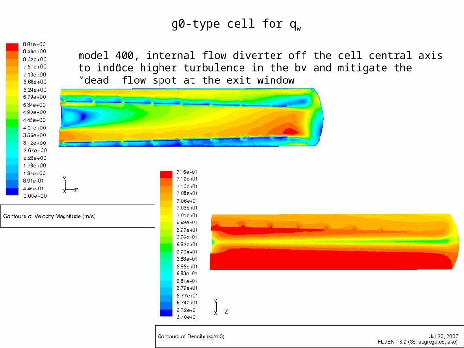
g0-type cell for qw
model 400, internal flow diverter off the cell central axis to induce higher turbulence in the bv and mitigate the “dead” flow spot at the exit window
qw t
ran
svers
e fl
ow
desi
gn
s
qw t
ran
svers
e fl
ow
desi
gn
s
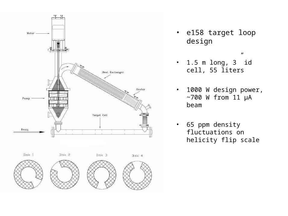
• e158 target loop design
• 1.5 m long, 3” id cell, 55 liters
• 1000 W design power, ~700 W from 11 µA beam
• 65 ppm density fluctuations on helicity flip scale
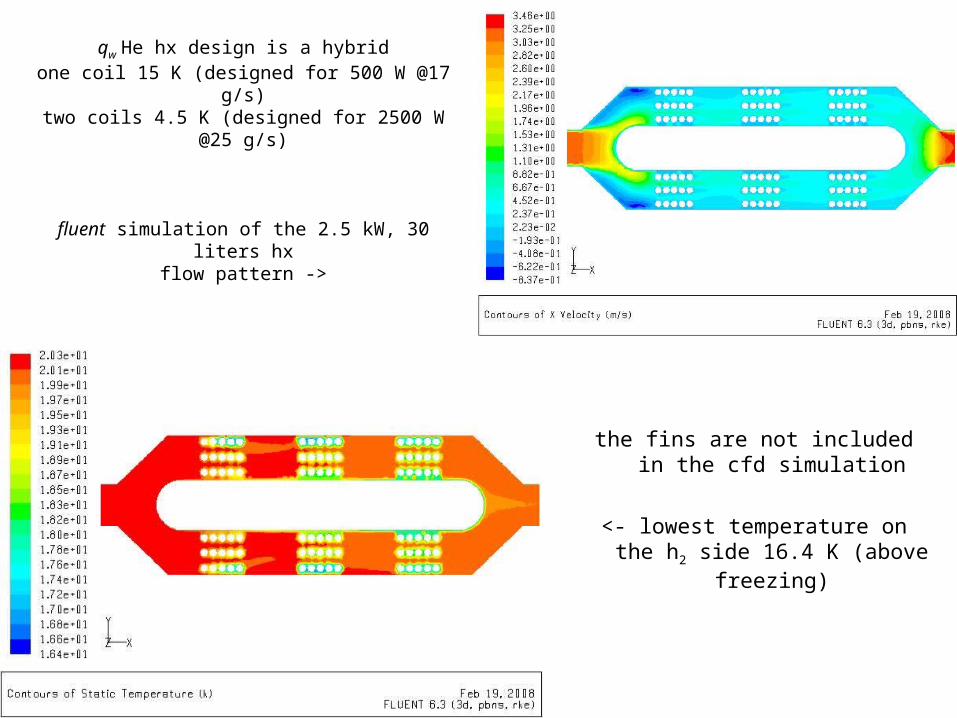
qw He hx design is a hybridone coil 15 K (designed for 500 W @17 g/s)
two coils 4.5 K (designed for 2500 W @25 g/s)
fluent simulation of the 2.5 kW, 30 liters hxflow pattern ->
the fins are not included in the cfd simulation
<- lowest temperature on the h2 side 16.4 K (above freezing)
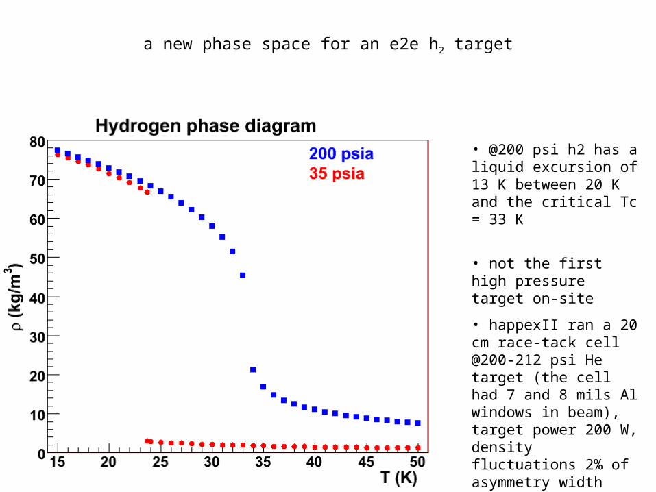
a new phase space for an e2e h2 target
• @200 psi h2 has a liquid excursion of 13 K between 20 K and the critical Tc = 33 K
• not the first high pressure target on-site
• happexII ran a 20 cm race-tack cell @200-212 psi He target (the cell had 7 and 8 mils Al windows in beam), target power 200 W, density fluctuations 2% of asymmetry width
remarks
• qw is the first target on-site designed using cfd simulations (cell, hph, crude hx check), has 4x the g0 flow, 5x the power for 8x the volume @twice the raster -> goal to get 10x better density fluctuations (we’ll know when we’ll measure it)
• cfd is a tremendous design help -> for now limited to the steady-state uniform heating in the raster volume (meaning density reduction) -> a realistic model for density fluctuations could be developed based on qw experience
• e2e is 2.6x the qw target power in beam volume -> density reduction could be a problem
• e2e cell windows heating should be no worse than g0• viscous heating could limit the flow in the loop to no more than 1 kg/s• cooling power has to be investigated carefully, 6 kW needs about 50 g/s CHL
helium
• 10x better than qw density fluctuations will be a challenge, a clear picture of this if qw achieves its goal here