LASER EDGE SENSOR I SERIES - Movetec Oy · NEW Multi-Purpose CCD Laser Micrometre IG Series A Wide...
16
NEW Multi-Purpose CCD Laser Micrometre IG Series A Wide Variety of Application Modes for Easy, High-Accuracy Measurements LASER EDGE SENSOR I - SERIES Intelligent Sensor Low-cost High Performance
Transcript of LASER EDGE SENSOR I SERIES - Movetec Oy · NEW Multi-Purpose CCD Laser Micrometre IG Series A Wide...
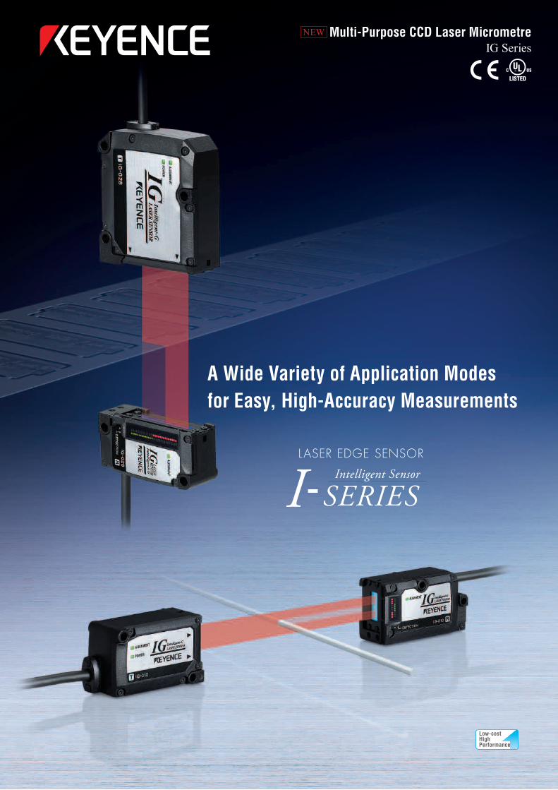
NEW Multi-Purpose CCD Laser MicrometreIG Series
A Wide Variety of Application Modes for Easy, High-Accuracy Measurements
LASER EDGE SENSOR
I-SERIESIntelligent Sensor
Low-costHighPerformance
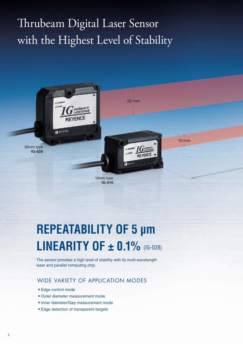
Thrubeam Digital Laser Sensor with the Highest Level of Stability
REPEATABILITY OF 5 μmLINEARITY OF ± 0.1% (IG-028)
The sensor provides a high level of stability with its multi-wavelength laser and parallel computing chip.
WIDE VARIETY OF APPLICATION MODES• Edge control mode
• Outer diameter measurement mode
• Inner diameter/Gap measurement mode
• Edge detection of transparent targets
28mm typeIG-028
10mm typeIG-010
28 mm
10 mm
2
3
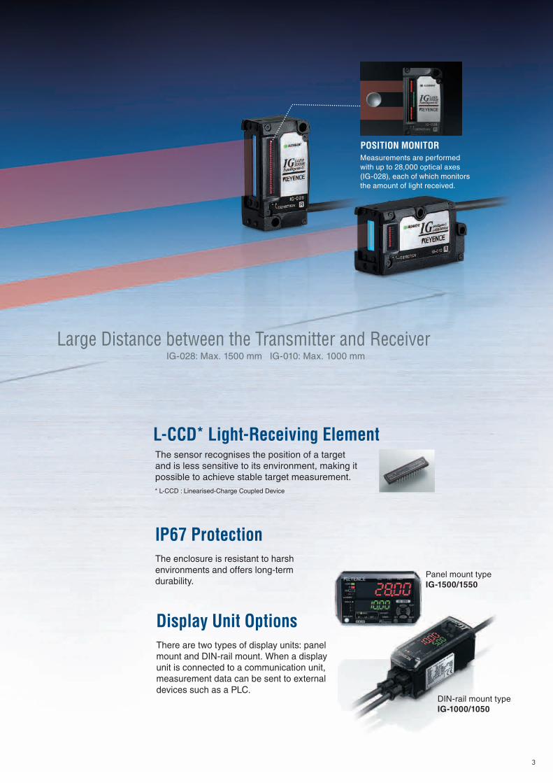
Large Distance between the Transmitter and ReceiverIG-028: Max. 1500 mm IG-010: Max. 1000 mm
Measurements are performed with up to 28,000 optical axes (IG-028), each of which monitors the amount of light received.
POSITION MONITOR
IP67 ProtectionThe enclosure is resistant to harsh environments and offers long-term durability.
Display Unit OptionsThere are two types of display units: panel mount and DIN-rail mount. When a display unit is connected to a communication unit, measurement data can be sent to external devices such as a PLC.
The sensor recognises the position of a target and is less sensitive to its environment, making it possible to achieve stable target measurement.
L-CCD* Light-Receiving Element
* L-CCD : Linearised-Charge Coupled Device
Panel mount typeIG-1500/1550
DIN-rail mount typeIG-1000/1050
Linearity of ±0.1%
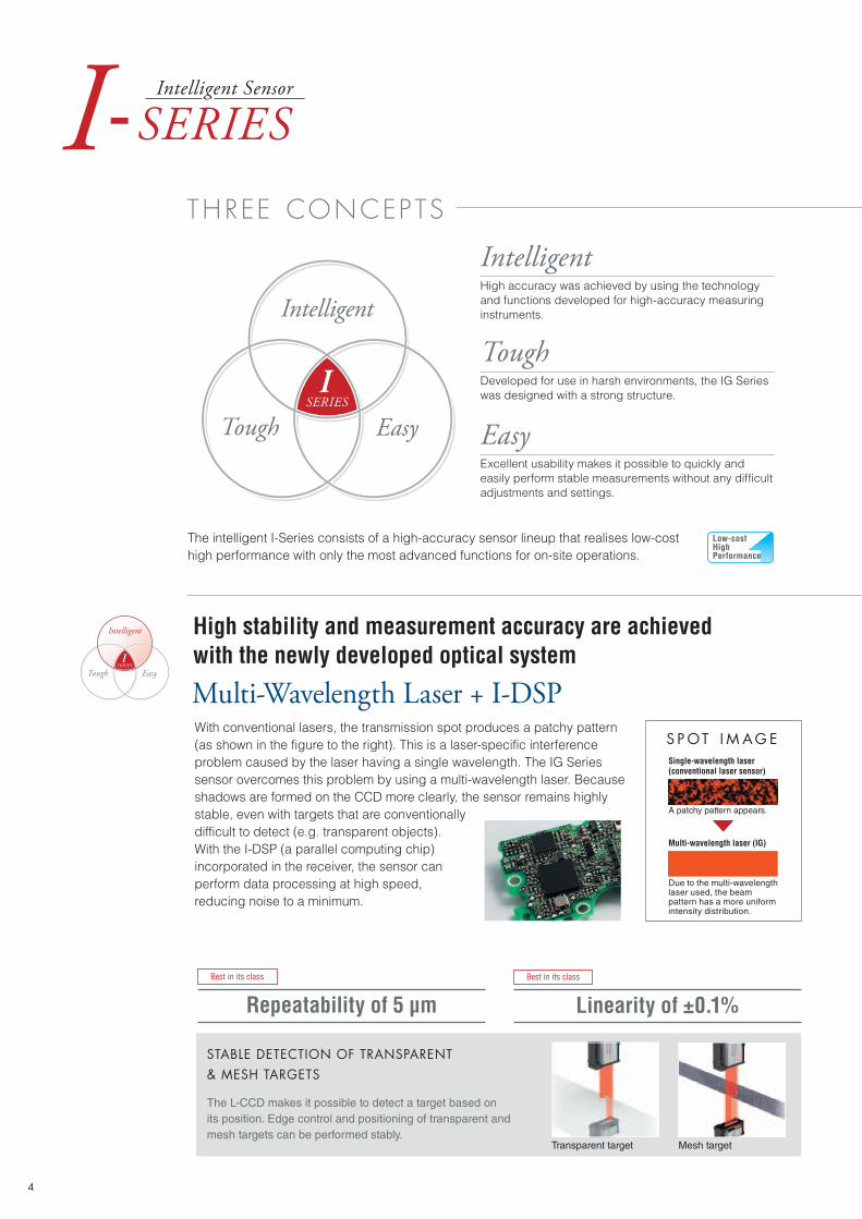
High stability and measurement accuracy are achieved with the newly developed optical system
Multi-Wavelength Laser + I-DSPWith conventional lasers, the transmission spot produces a patchy pattern (as shown in the figure to the right). This is a laser-specific interference problem caused by the laser having a single wavelength. The IG Series sensor overcomes this problem by using a multi-wavelength laser. Because shadows are formed on the CCD more clearly, the sensor remains highly stable, even with targets that are conventionally difficult to detect (e.g. transparent objects). With the I-DSP (a parallel computing chip) incorporated in the receiver, the sensor can perform data processing at high speed, reducing noise to a minimum.
S P OT I M A G ESingle-wavelength laser (conventional laser sensor)
A patchy pattern appears.
Due to the multi-wavelength laser used, the beam pattern has a more uniform intensity distribution.
Repeatability of 5 μmBest in its class Best in its class
STABLE DETECTION OF TRANSPARENT & MESH TARGETS
The L-CCD makes it possible to detect a target based on its position. Edge control and positioning of transparent and mesh targets can be performed stably.
Transparent target Mesh target
Multi-wavelength laser (IG)
Intelligent
Tough
Easy
THREE CONCEPTS
The intelligent I-Series consists of a high-accuracy sensor lineup that realises low-cost high performance with only the most advanced functions for on-site operations.
High accuracy was achieved by using the technology and functions developed for high-accuracy measuring instruments.
Developed for use in harsh environments, the IG Series was designed with a strong structure.
Excellent usability makes it possible to quickly and easily perform stable measurements without any difficult adjustments and settings.
4
I-SERIESIntelligent Sensor
SERIES
Intelligent
Tough Easy
I
SERIES
Intelligent
Tough Easy
I
SERIES
Intelligent
Tough Easy
I
SERIES
Intelligent
Tough Easy
I
SERIES
Intelligent
Tough Easy
I
SERIES
Intelligent
Tough Easy
I
SERIES
Intelligent
Tough Easy
I
SERIES
Intelligent
Tough Easy
I
Low-costHighPerformance
5
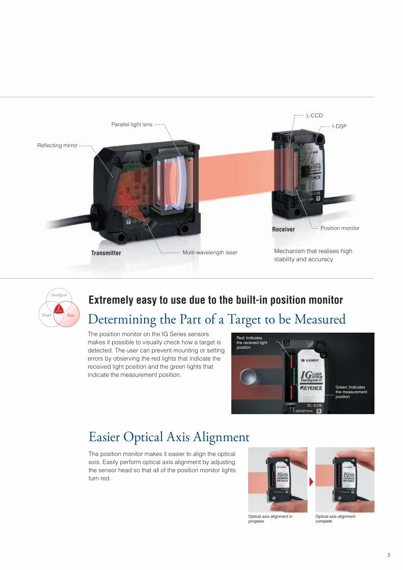
Red: Indicates the received light position
Green: Indicates the measurement position
The position monitor on the IG Series sensors makes it possible to visually check how a target is detected. The user can prevent mounting or setting errors by observing the red lights that indicate the received light position and the green lights that indicate the measurement position.
Extremely easy to use due to the built-in position monitor
Determining the Part of a Target to be Measured
Optical axis alignment in progress
Easier Optical Axis AlignmentThe position monitor makes it easier to align the optical axis. Easily perform optical axis alignment by adjusting the sensor head so that all of the position monitor lights turn red.
Optical axis alignment complete
Mechanism that realises high stability and accuracy
Reflecting mirror
Parallel light lens
Multi-wavelength laser
Position monitor
I-DSP
L-CCD
Transmitter
Receiver
SERIES
Intelligent
Tough Easy
I
SERIES
Intelligent
Tough Easy
I
SERIES
Intelligent
Tough Easy
I
SERIES
Intelligent
Tough Easy
I
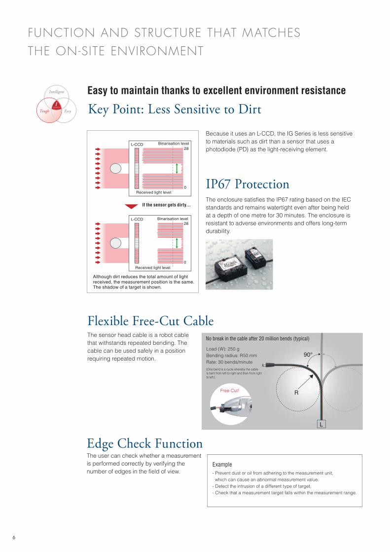
Although dirt reduces the total amount of light received, the measurement position is the same. The shadow of a target is shown.
Easy to maintain thanks to excellent environment resistance
Key Point: Less Sensitive to Dirt
Because it uses an L-CCD, the IG Series is less sensitive to materials such as dirt than a sensor that uses a photodiode (PD) as the light-receiving element.
IP67 ProtectionThe enclosure satisfies the IP67 rating based on the IEC standards and remains watertight even after being held at a depth of one metre for 30 minutes. The enclosure is resistant to adverse environments and offers long-term durability.
L-CCD
Received light level
Received light level
Binarisation level
Binarisation level
28
0
L-CCD28
0
If the sensor gets dirty...
Flexible Free-Cut CableThe sensor head cable is a robot cable that withstands repeated bending. The cable can be used safely in a position requiring repeated motion.
Edge Check FunctionThe user can check whether a measurement is performed correctly by verifying the number of edges in the field of view.
Example- Prevent dust or oil from adhering to the measurement unit, which can cause an abnormal measurement value.- Detect the intrusion of a different type of target.- Check that a measurement target falls within the measurement range.
90°
L
R
No break in the cable after 20 million bends (typical)
Load (W): 250 gBending radius: R50 mmRate: 30 bends/minute(One bend is a cycle whereby the cable is bent from left to right and then from right to left.)
Free Cut!
FUNCTION AND STRUCTURE THAT MATCHES THE ON-SITE ENVIRONMENT
6
SERIES
Intelligent
Tough Easy
I
SERIES
Intelligent
Tough Easy
I
SERIES
Intelligent
Tough Easy
I
SERIES
Intelligent
Tough Easy
I
7
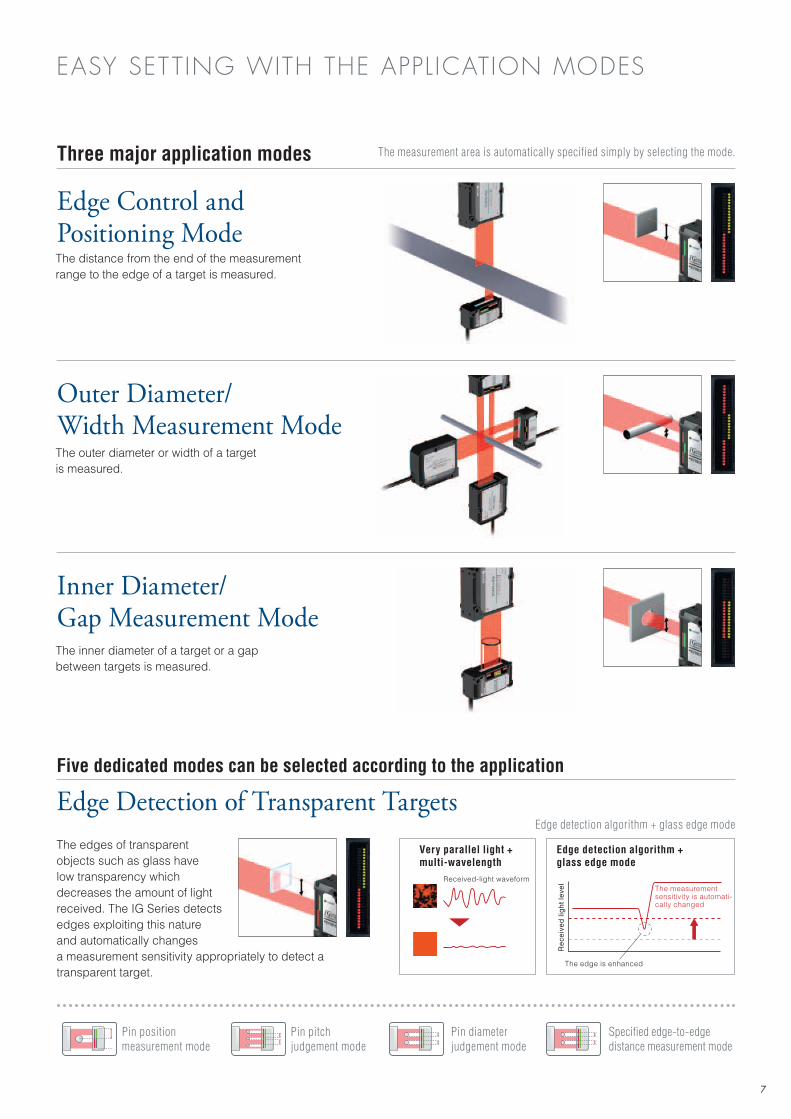
Edge Control and Positioning Mode
Outer Diameter/Width Measurement Mode
Inner Diameter/Gap Measurement Mode
The distance from the end of the measurement range to the edge of a target is measured.
The outer diameter or width of a target is measured.
The inner diameter of a target or a gap between targets is measured.
EASY SETTING WITH THE APPLICATION MODES
Three major application modes
Edge Detection of Transparent TargetsEdge detection algorithm + glass edge mode
Five dedicated modes can be selected according to the application
Pin position measurement mode
Pin pitch judgement mode
Pin diameter judgement mode
Specified edge-to-edge distance measurement mode
Very parallel light + multi-wavelength
Edge detection algorithm + glass edge mode
Received-light waveform
The edge is enhanced
The measurement sensitivity is automati-cally changed
Re
ceiv
ed
ligh
t le
vel
The edges of transparent objects such as glass have low transparency which decreases the amount of light received. The IG Series detects edges exploiting this nature and automatically changes a measurement sensitivity appropriately to detect a transparent target.
The measurement area is automatically specified simply by selecting the mode.
XY
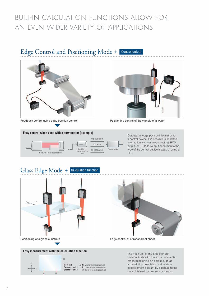
Edge Control and Positioning Mode + Control output
Glass Edge Mode + Calculation function
Feedback control using edge position control Positioning control of the θ angle of a wafer
Outputs the edge position information to a control device. It is possible to send the information via an analogue output, BCD output, or RS-232C output according to the type of the control device instead of using a PLC.
Positioning of a glass substrate Edge control of a transparent sheet
Easy measurement with the calculation function
Amplifier or communication
unitMeasures a position information
Easy control when used with a servomotor (example)
Analogue output
BCD output
RS-232C output
BUILT- IN CALCULATION FUNCTIONS ALLOW FOR AN EVEN WIDER VARIETY OF APPLICATIONS
The main unit of the amplifier can communicate with the expansion units. When positioning an object such as a panel, it is possible to calculate a misalignment amount by calculating the data obtained by two sensor heads.
8
Control device
A−B :B :C :
Misalignment measurementY-axis position measurementX-axis position measurement
Main unitExpansion unit 1Expansion unit 2
A B
C
X
Y
9
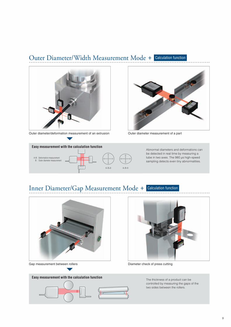
Outer diameter/deformation measurement of an extrusion Outer diameter measurement of a part
Gap measurement between rollers Diameter check of press cutting
Abnormal diameters and deformations can be detected in real time by measuring a tube in two axes. The 980 µs high-speed sampling detects even tiny abnormalities.
The thickness of a product can be controlled by measuring the gaps of the two sides between the rollers.
Outer Diameter/Width Measurement Mode + Calculation function
Easy measurement with the calculation function
A-B:B :
Deformation measurementOuter diameter measurement
Easy measurement with the calculation function
A−B=0 A−B≠0
Inner Diameter/Gap Measurement Mode + Calculation function
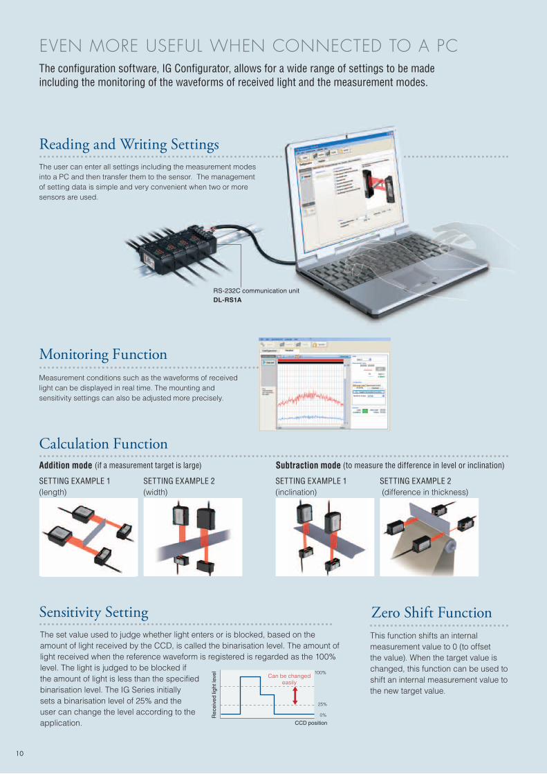
Reading and Writing SettingsThe user can enter all settings including the measurement modes into a PC and then transfer them to the sensor. The management of setting data is simple and very convenient when two or more sensors are used.
Monitoring FunctionMeasurement conditions such as the waveforms of received light can be displayed in real time. The mounting and sensitivity settings can also be adjusted more precisely.
Calculation FunctionAddition mode (if a measurement target is large)
SETTING EXAMPLE 1 (length)
SETTING EXAMPLE 2 (width)
Subtraction mode (to measure the difference in level or inclination)
SETTING EXAMPLE 1(inclination)
SETTING EXAMPLE 2 (difference in thickness)
Sensitivity SettingThe set value used to judge whether light enters or is blocked, based on the amount of light received by the CCD, is called the binarisation level. The amount of light received when the reference waveform is registered is regarded as the 100% level. The light is judged to be blocked if the amount of light is less than the specified binarisation level. The IG Series initially sets a binarisation level of 25% and the user can change the level according to the application.
Zero Shift FunctionThis function shifts an internal measurement value to 0 (to offset the value). When the target value is changed, this function can be used to shift an internal measurement value to the new target value.
The configuration software, IG Configurator, allows for a wide range of settings to be made including the monitoring of the waveforms of received light and the measurement modes.
Rec
eive
d lig
ht le
vel
Can be changed easily
CCD position
100%
25%
0%
EVEN MORE USEFUL WHEN CONNECTED TO A PC
RS-232C communication unitDL-RS1A
10
11
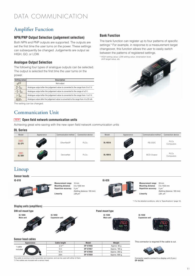
Lineup
NPN/PNP Output Selection (judgement selection)Both NPN and PNP outputs are supported. The outputs are set the first time the user turns on the power. These settings can subsequently be changed. Judgements are output as HIGH, GO, or LOW.
Analogue Output SelectionThe following four types of analogue outputs can be selected.The output is selected the first time the user turns on the power.
The setting can be changed.
Setting value Description
Not output
Analogue output after the judgement value is converted to the range from 0 to 5 V.
Analogue output after the judgement value is converted to the range of ±5 V.
Analogue output after the judgement value is converted to the range from 1 to 5 V.
Analogue output after the judgement value is converted to the range from 4 to 20 mA.
*1 For the detailed conditions, refer to "Specifications" (page 12).
Sensor head cablesAppearance Cable length Model Weight
2 m* 2 OP-87056 Approx. 80 g
5 m OP-87057 Approx. 190 g
10 m OP-87058 Approx. 360 g
20m OP-87059 Approx. 680 g
The cable is common to the transmitter and receiver, and can be used with either of them.*2 Two cables are included with a sensor head.
This connector is required if the cable is cut.
Connector used to connect to a display unit (2 pcs.)OP-84338
Measurement rangeMounting distanceRepetition accuracy
Linearity
10 mm0 to 1000 mm5 μm *1 (Setting distance: 100 mm)±28 μm*1
IG-010 IG-028Measurement rangeMounting distanceRepetition accuracy
Linearity
28 mm0 to 1500 mm5 μm*1 (Setting distance: 100 mm)±28 μm*1
Sensor heads
Display units (amplifiers)
DIN rail mount typeIG-1000Main unit
IG-1050Expansion unit
IG-1500Main unit
IG-1550Expansion unit
Panel mount type
Amplifier Function
Communication Unit
Achieving great wire-saving with the new open field network communication units
Model Appearance Communication method Connection device
DL-EP1 EtherNet/IP PLCs
DL-DN1 DeviceNet PLCs
Model Appearance Communication method Connection device
DL-RS1A RS-232CPLCs
Computers
DL-RB1A BCD-OutputPLCs
Computers
Open field network communication units
DL Series
NEW
NEW
NEW
1 cable included
DATA COMMUNICATION
The bank function can register up to four patterns of specific settings.* For example, in response to a measurement target changeover, this function allows the user to easily switch between the patterns of registered settings.* HIGH setting value, LOW setting value, binarisation level, shift target value, etc.
Bank Function
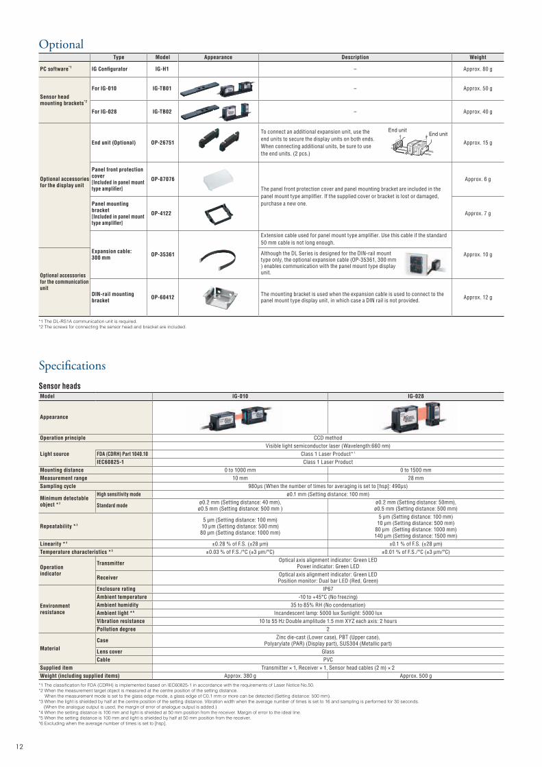
OptionalType Model Appearance Description Weight
PC software*1 IG Configurator IG-H1 - Approx. 80 g
Sensor head mounting brackets*2
For IG-010 IG-TB01 - Approx. 50 g
For IG-028 IG-TB02 - Approx. 40 g
Optional accessories for the display unit
End unit (Optional) OP-26751
To connect an additional expansion unit, use the end units to secure the display units on both ends. When connecting additional units, be sure to use the end units. (2 pcs.)
Approx. 15 g
Panel front protection cover[Included in panel mount type amplifier]
OP-87076
The panel front protection cover and panel mounting bracket are included in the panel mount type amplifier. If the supplied cover or bracket is lost or damaged, purchase a new one.
Approx. 6 g
Panel mounting bracket[Included in panel mount type amplifier]
OP-4122 Approx. 7 g
Expansion cable: 300 mm OP-35361
Extension cable used for panel mount type amplifier. Use this cable if the standard 50 mm cable is not long enough.
Approx. 10 g
Optional accessories for the communication unit
Although the DL Series is designed for the DIN-rail mount type only, the optional expansion cable (OP-35361, 300 mm ) enables communication with the panel mount type display unit.
DIN-rail mounting bracket OP-60412 The mounting bracket is used when the expansion cable is used to connect to the
panel mount type display unit, in which case a DIN rail is not provided. Approx. 12 g
*1 The DL-RS1A communication unit is required.*2 The screws for connecting the sensor head and bracket are included.
SpecificationsSensor headsModel IG-010 IG-028
Appearance
Operation principle CCD method
Light sourceVisible light semiconductor laser (Wavelength:660 nm)
FDA (CDRH) Part 1040.10 Class 1 Laser Product*1
IEC60825-1 Class 1 Laser ProductMounting distance 0 to 1000 mm 0 to 1500 mm Measurement range 10 mm 28 mm Sampling cycle 980μs (When the number of times for averaging is set to [hsp]: 490μs)
Minimum detectable object *2
High sensitivity mode ø0.1 mm (Setting distance: 100 mm)
Standard mode ø0.2 mm (Setting distance: 40 mm), ø0.5 mm (Setting distance: 500 mm )
ø0.2 mm (Setting distance: 50mm), ø0.5 mm (Setting distance: 500 mm)
Repeatability *35 μm (Setting distance: 100 mm)
10 μm (Setting distance: 500 mm)80 μm (Setting distance: 1000 mm)
5 μm (Setting distance: 100 mm)10 μm (Setting distance: 500 mm)
80 μm (Setting distance: 1000 mm)140 μm (Setting distance: 1500 mm)
Linearity *4 ±0.28 % of F.S. (±28 μm) ±0.1 % of F.S. (±28 μm)Temperature characteristics *5 ±0.03 % of F.S./°C (±3 μm/°C) ±0.01 % of F.S./°C (±3 μm/°C)
Operationindicator
Transmitter Optical axis alignment indicator: Green LEDPower indicator: Green LED
Receiver Optical axis alignment indicator: Green LEDPosition monitor: Dual bar LED (Red, Green)
Environmentresistance
Enclosure rating IP67Ambient temperature -10 to +45°C (No freezing)Ambient humidity 35 to 85% RH (No condensation)Ambient light *6 Incandescent lamp: 5000 lux Sunlight: 5000 luxVibration resistance 10 to 55 Hz Double amplitude 1.5 mm XYZ each axis: 2 hoursPollution degree 2
MaterialCase Zinc die-cast (Lower case), PBT (Upper case),
Polyarylate (PAR) (Display part), SUS304 (Metallic part)Lens cover GlassCable PVC
Supplied item Transmitter × 1, Receiver × 1, Sensor head cables (2 m) × 2Weight (including supplied items) Approx. 380 g Approx. 500 g
*1 The classification for FDA (CDRH) is implemented based on IEC60825-1 in accordance with the requirements of Laser Notice No.50.*2 When the measurement target object is measured at the centre position of the setting distance. When the measurement mode is set to the glass edge mode, a glass edge of C0.1 mm or more can be detected (Setting distance: 500 mm).*3 When the light is shielded by half at the centre position of the setting distance. Vibration width when the average number of times is set to 16 and sampling is performed for 30 seconds. (When the analogue output is used, the margin of error of analogue output is added.)*4 When the setting distance is 100 mm and light is shielded at 50 mm position from the receiver. Margin of error to the ideal line.*5 When the setting distance is 100 mm and light is shielded by half at 50 mm position from the receiver.*6 Excluding when the average number of times is set to [hsp].
End unitEnd unit
12
13
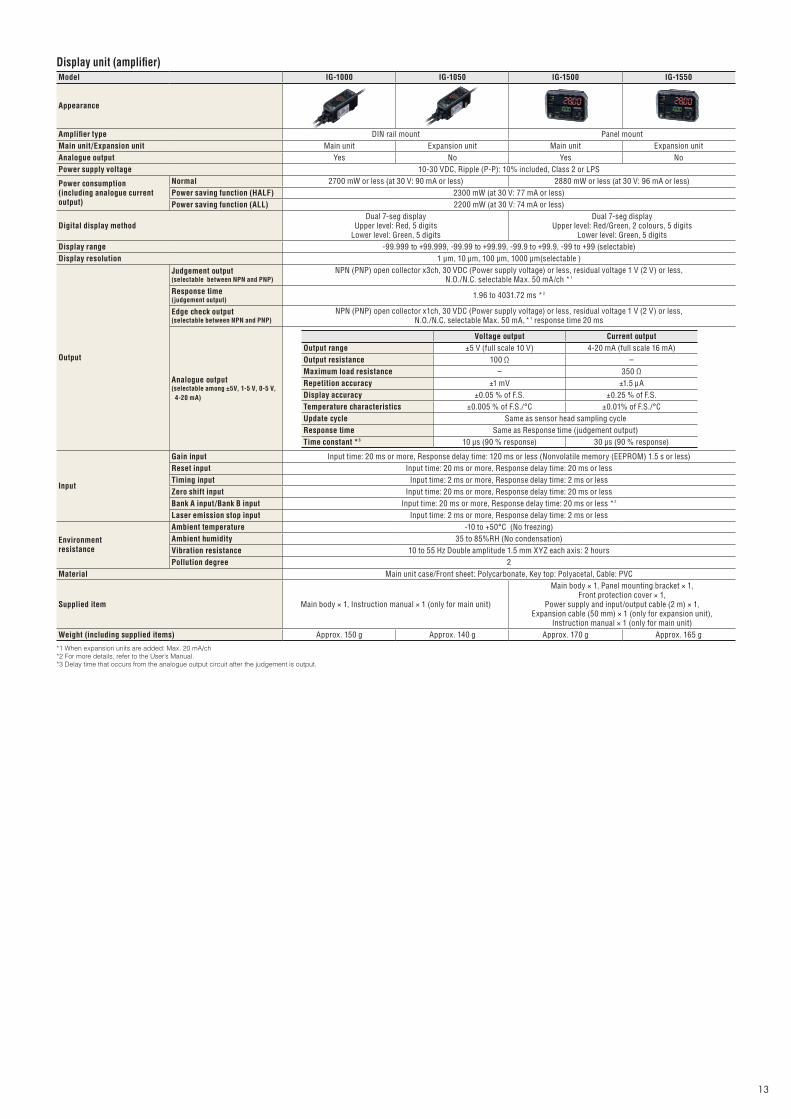
Display unit (amplifier)Model IG-1000 IG-1050 IG-1500 IG-1550
Appearance
Amplifier type DIN rail mount Panel mountMain unit/Expansion unit Main unit Expansion unit Main unit Expansion unitAnalogue output Yes No Yes NoPower supply voltage 10-30 VDC, Ripple (P-P): 10% included, Class 2 or LPS
Power consumption (including analogue current output)
Normal 2700 mW or less (at 30 V: 90 mA or less) 2880 mW or less (at 30 V: 96 mA or less)Power saving function (HALF) 2300 mW (at 30 V: 77 mA or less)Power saving function (ALL) 2200 mW (at 30 V: 74 mA or less)
Digital display methodDual 7-seg display
Upper level: Red, 5 digitsLower level: Green, 5 digits
Dual 7-seg displayUpper level: Red/Green, 2 colours, 5 digits
Lower level: Green, 5 digitsDisplay range -99.999 to +99.999, -99.99 to +99.99, -99.9 to +99.9, -99 to +99 (selectable)Display resolution 1 μm, 10 μm, 100 μm, 1000 μm(selectable )
Output
Judgement output(selectable between NPN and PNP)
NPN (PNP) open collector x3ch, 30 VDC (Power supply voltage) or less, residual voltage 1 V (2 V) or less, N.O./N.C. selectable Max. 50 mA/ch *1
Response time(judgement output)
1.96 to 4031.72 ms *2
Edge check output(selectable between NPN and PNP)
NPN (PNP) open collector x1ch, 30 VDC (Power supply voltage) or less, residual voltage 1 V (2 V) or less, N.O./N.C. selectable Max. 50 mA, *1 response time 20 ms
Analogue output(selectable among ±5V, 1-5 V, 0-5 V, 4-20 mA)
Input
Gain input Input time: 20 ms or more, Response delay time: 120 ms or less (Nonvolatile memory (EEPROM) 1.5 s or less)Reset input Input time: 20 ms or more, Response delay time: 20 ms or lessTiming input Input time: 2 ms or more, Response delay time: 2 ms or lessZero shift input Input time: 20 ms or more, Response delay time: 20 ms or lessBank A input/Bank B input Input time: 20 ms or more, Response delay time: 20 ms or less *2
Laser emission stop input Input time: 2 ms or more, Response delay time: 2 ms or less
Environment resistance
Ambient temperature -10 to +50°C (No freezing)Ambient humidity 35 to 85%RH (No condensation)Vibration resistance 10 to 55 Hz Double amplitude 1.5 mm XYZ each axis: 2 hoursPollution degree 2
Material Main unit case/Front sheet: Polycarbonate, Key top: Polyacetal, Cable: PVC
Supplied item Main body × 1, Instruction manual × 1 (only for main unit)
Main body × 1, Panel mounting bracket × 1, Front protection cover × 1,
Power supply and input/output cable (2 m) × 1, Expansion cable (50 mm) × 1 (only for expansion unit),
Instruction manual × 1 (only for main unit)Weight (including supplied items) Approx. 150 g Approx. 140 g Approx. 170 g Approx. 165 g
*1 When expansion units are added: Max. 20 mA/ch*2 For more details, refer to the User’s Manual.*3 Delay time that occurs from the analogue output circuit after the judgement is output.
Voltage output Current outputOutput range ±5 V (full scale 10 V) 4-20 mA (full scale 16 mA)Output resistance 100 Ω -Maximum load resistance - 350 ΩRepetition accuracy ±1 mV ±1.5 μADisplay accuracy ±0.05 % of F.S. ±0.25 % of F.S.Temperature characteristics ±0.005 % of F.S./°C ±0.01% of F.S./°CUpdate cycle Same as sensor head sampling cycleResponse time Same as Response time (judgement output)Time constant *3 10 μs (90 % response) 30 μs (90 % response)
(26)ø9
2-ø3.4 (Mounting hole)
17
ø4.8 Cable length 170Edge M8 connector
39.854.7
6.7 3.2
25.4
Transmission spot centre
2311.2
18.831.8
3-M3 Valid screw depth 4
10.41.6
50.5
32.7 10.6 4.86.7
3.7
* Transmission spot (reference value)12
15
Base level
2-M4 Valid screw depth 5.2
Measurementcentre
* Light-receiving area (5 × 14 rectangle)
31.818.8±1
11.223
51.5 12.6
23.5 28.555
16.2
2-ø3.4(Mounting hole)
(26) ø9
3-M3 Valid screw depth 4
3 49.4 4.3
13.5
Base level
2-M4 Valid screw depth 5.2
* Light-receiving area (3.6 × 31.2 rectangle)
Measurementcentre
56.2
33.1±0.3
11.423
48.2
4.1
2-ø4.5 (Mounting hole)
7 17.1 11.430.2
29.3
15.5
4.3 2.518.5
16.6
0.83-M3 Valid screw depth 5.5
Base level
Base level2-M5 Valid screwdepth 5.2
47.616.6
6.4
(26)
ø9
18.8 25.4 11.566.2
4.2
47.5
11.423
33.1
56.2
3-ø4.5 (Mounting hole)
Transmission spot centre
4-M3 Valid screw depth 5.5 63.8
43.8 6.54.8
10.4
Base level
10.41.8 1233
* Transmission spot (reference value)
3-M5 Valid screw depth 5.2Base level
ø4.8 Cable length 170Edge M8 connector
ø4.8 Cable length 170Edge M8 connector ø4.8 Cable length 170
Edge M8 connector
(26) ø9
50 2656(4.2)(10.2)
(146.4)11.4
28
6.1
16.4
61.261.2
28
38.1±0.3
(17.6)
(45.6)
(24.1)
(52.1)
17 46.782.7
11.5
23
11.4(Measurement centre)
Measurement areaTransmitter Receiver
40
151.1144
23
36.836.822
23.8±1
10
56.4(47.6)
11.5
67.917
(18.8)
(28.8)
(66.2)
(12.3)
(22.3)
11.4 (Measurement
centre) Measurement area
2-ø4.5 Drilled through holeø8.5 Spot facing depth 4
Transmitter Receiver
2-ø4.5 Drilled through holeø8.5 Spot facing depth 4
Material: Aluminium Material: Aluminium
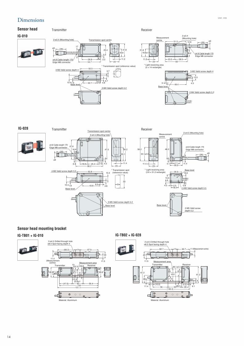
Unit : mmDimensions Sensor head
IG-010
IG-028
Transmitter Receiver
Transmitter Receiver
Sensor head mounting bracket
IG-TB01 + IG-010 IG-TB02 + IG-028
14
15
28.3
8.9
18.5
Cable diameter ø4.8
Cable diameter ø4.7 Cable length 2 m
18.5
37.442.4
17.4
3
20 21.6 35.476.3
17.6
Max.135°
When the cover isopen: Max. 109.2
Min.15Min.15
37.442.4
17.4
3
20 21.6 35.476.3
17.6
Max.135°
When the cover isopen: Max. 109.2
18.528.318.5
1.9 (4.8)19.2
69.5
8.9
Cable diameter ø4.8 Cable diameter ø4.7 Cable length 2 m
Min.15Min.15
6
(22.6) 20.8
9.2 35.453.8
Brown *1
Blue *1
Black
White
Grey
Light blue *1Orange *2
Shield *2
Pink *3
Yellow *3
Pink/purple *3
Purple *3
Green
10 to 30 VDC
0 V
HIGH judgement output
LOW judgement output
GO judgement output
Analogue output +
Analogue output GND
External input 1 (zero shift input)
External input 2 (reset input)
External input 3 (timing input)
External input 4 (not used)
Edge check output
44.7
2.37.6
1.5
48
73.6
19.1
10.3
19.1
17.627.2
44.715.3
9.535
20.2
4 62.5
12.4
Panel thickness 1 to 6 mm
45mm+0.6-0
45mm +0.6-0
Min.85mm
Xmm
45mm +0.6-0
X = 48 × (number of amplifiers) - 3
Cable diameter ø4.8Cable diameter ø4.7 Cable length 2 m
76
22.410.3
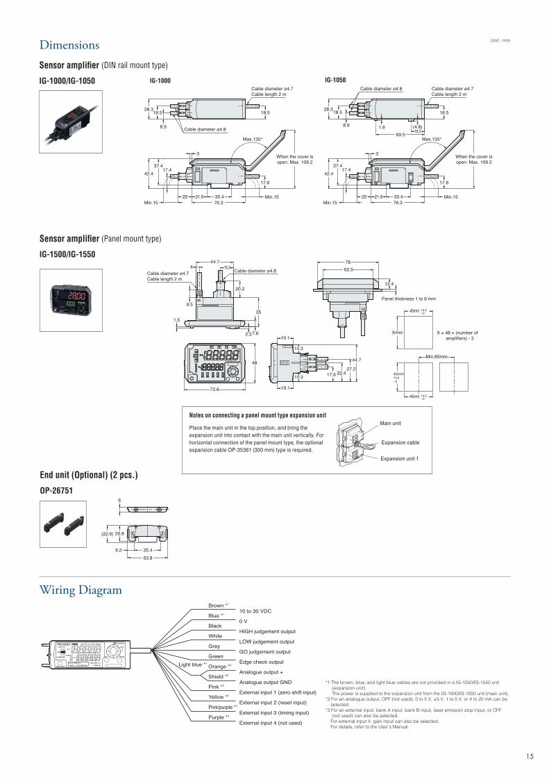
Unit : mmDimensionsSensor amplifier (DIN rail mount type)
IG-1000/IG-1050
Sensor amplifier (Panel mount type)
IG-1500/IG-1550
End unit (Optional) (2 pcs.)
OP-26751
IG-1000 IG-1050
Wiring Diagram
*1 The brown, blue, and light blue cables are not provided in a IG-1050/IG-1550 unit (expansion unit). The power is supplied to the expansion unit from the IG-1000/IG-1500 unit (main unit).*2 For an analogue output, OFF (not used), 0 to 5 V, ±5 V, 1 to 5 V, or 4 to 20 mA can be selected.*3 For an external input, bank A input, bank B input, laser emission stop input, or OFF (not used) can also be selected. For external input 4, gain input can also be selected. For details, refer to the User’s Manual.
Notes on connecting a panel mount type expansion unit
Place the main unit in the top position, and bring the expansion unit into contact with the main unit vertically. For horizontal connection of the panel mount type, the optional expansion cable OP-35361 (300 mm) type is required.
Main unit
Expansion cable
Expansion unit 1
WW1-1013
www.keyence.comSAFETY INFORMATIONPlease read the instruction manual carefully in order to safely operate any KEYENCE product.
Please visit:
AUSTRIAPhone: +43 22 36-3782 66-0 Fax: +43 22 36-3782 66-30BELGIUMPhone: +32 1 528 1222 Fax: +32 1 520 1623BRAZILPhone: +55-11-3045-4011 Fax: +55-11-3045-5219CANADAPhone: +1-905-366-7655 Fax: +1-905-366-1122CHINAPhone: +86-21-68757500 Fax: +86-21-68757550CZECH REPUBLICPhone: +420 222 191 483 Fax: +420 222 191 505FRANCEPhone: +33 1 56 37 78 00 Fax: +33 1 56 37 78 01
GERMANYPhone: +49 61 02 36 89-0 Fax: +49 61 02 36 89-100HONG KONGPhone: +852-3104-1010 Fax: +852-3104-1080HUNGARYPhone: +36 1 802 73 60 Fax: +36 1 802 73 61INDIAPhone: +91-44-4963-0900 Fax: +91-44-4963-0901ITALYPhone: +39-02-6688220 Fax: +39-02-66825099JAPANPhone: +81-6-6379-2211 Fax: +81-6-6379-2131KOREAPhone: +82-31-789-4300 Fax: +82-31-789-4301
MALAYSIAPhone: +60-3-2092-2211 Fax: +60-3-2092-2131MEXICOPhone: +52-81-8220-7900 Fax: +52-81-8220-9097NETHERLANDSPhone: +31 40 20 66 100 Fax: +31 40 20 66 112POLANDPhone: +48 71 36861 60 Fax: +48 71 36861 62ROMANIAPhone: +40 269-232-808 Fax: +40 269-232-808SINGAPOREPhone: +65-6392-1011 Fax: +65-6392-5055SLOVAKIAPhone: +421 2 5939 6461 Fax: +421 2 5939 6200
SLOVENIAPhone: +386 1-4701-666 Fax: +386 1-4701-699SWITZERLANDPhone: +41 43-45577 30 Fax: +41 43-45577 40TAIWANPhone: +886-2-2718-8700 Fax: +886-2-2718-8711THAILANDPhone: +66-2-369-2777 Fax: +66-2-369-2775UK & IRELANDPhone: +44-1908-696900 Fax: +44-1908-696777USA Phone: +1-201-930-0100 Fax: +1-201-930-0099
KEYENCE CORPORATION1-3-14, Higashi-Nakajima, Higashi-Yodogawa-ku, Osaka, 533-8555, Japan Phone: +81-6-6379-2211
Copyright (c) 2010 KEYENCE CORPORATION. All rights reserved. IG-WW-C-E 1093-5 600699 Printed in JapanThe information in this publication is based on KEYENCE’s internal research/evaluation at the time of release and is subject to change without notice.
* 6 0 0 6 9 9 *
29.4
25.6
(42.5)
43.594.5
35.4
38.1(42.2)
56.3
78.235.424.1
35.549.5
37.7
2.4
29.4
When coveropen, maximum
of 58.3
Max.125°
7035.421.1
43.8
22.5
(48.2) 37.2
7035.421.1
53.4
37.1
22.5
(57.8)
Unit : mm
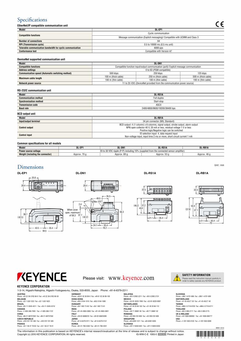
Specifications
Model DL-DN1Compatible functions Compatible function input/output communication (poll)/ Explicit message communicationAddress settings 0 to 63 (PGM compatible)Communication speed (Automatic switching method) 500 kbps 250 kbps 125 kbps
Maximum cable length100 m (thick cable) 250 m (thick cable) 500 m (thick cable)100 m (thin cable) 100 m (thin cable) 100 m (thin cable)
Network power source 11 to 25 VDC (DeviceNet provided from the communication power source)
DeviceNet supported communication unit
Model DL-RS1ACommunication method Full duplexSynchronisation method Start-stopTransmission code ASCIIBaud rate 2400/4800/9600/19200/38400 bps
RS-232C communication unit
Model DL-RB1AInput/output terminal 34 pin connector (MIL Standard)
Control outputBCD output: 4 (1 column) x 6 columns, signal output, strobe output, alarm output
NPN open collector 40 V, 20 mA or less, residual voltage 1 V or less Positive logic/Negative logic can be switched
Control input ID selection input: 4, data request inputNon-voltage input, input time 2 ms or more, short circuit current 1 mA
BCD output unit
Model DL-EP1 DL-DN1 DL-RS1A DL-RB1APower source voltage 20 to 30 VDC ripple (P-P) including 10% (supplied from the connected sensor amplifier)Weight (including the connector) Approx. 70 g Approx. 80 g Approx. 53 g Approx. 46 g
Common specifications for all models
DL-DN1 DL-RS1A DL-RB1A
Model DL-EP1
Compatible functionsCyclic communication
Message communication (Explicit messaging)/ Compatible with UCMM and Class 3Number of connections 64RPI (Transmission cycle) 0.5 to 10000 ms (0.5 ms unit)Tolerable communication bandwidth for cyclic communication 6000 ppsConformance test Compatible with Version A7
EtherNet/IP compatible communication unit
DL-EP1
Dimensions