L L LT T ( ) L LT α - University of Arizona · ∆= ∆LL T α. 2. Add reaction ... Determine...
17
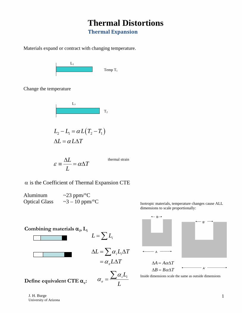
J. H. Burge University of Arizona 1 Thermal Distortions Thermal Expansion Materials expand or contract with changing temperature. Change the temperature ( ) 2 1 2 1 L L LT T L LT L T L α α ε α − = − ∆ = ∆ ∆ ≡ = ∆ thermal strain α is the Coefficient of Thermal Expansion CTE Aluminum ~23 ppm/°C Optical Glass ~3 – 10 ppm/°C Temp T 1 T 2 L 2 L 1 Isotropic materials, temperature changes cause ALL dimensions to scale proportionally: Inside dimensions scale the same as outside dimensions A A’ B B’ A A T B B T α α ∆ = ∆ ∆ = ∆ Combining materials α i , L i ∑ = i L L T L T L L e i i ∆ = ∆ = ∆ ∑ α α L L i i e ∑ = α α Define equivalent CTE α e :
Transcript of L L LT T ( ) L LT α - University of Arizona · ∆= ∆LL T α. 2. Add reaction ... Determine...
J. H. Burge University of Arizona
1
Thermal Distortions Thermal Expansion
Materials expand or contract with changing temperature. Change the temperature
( )2 1 2 1L L L T TL L T
L TL
α
α
ε α
− = −
∆ = ∆
∆≡ = ∆
thermal strain
α is the Coefficient of Thermal Expansion CTE Aluminum ~23 ppm/°C Optical Glass ~3 – 10 ppm/°C
Temp T1
T2
L2
L1
Isotropic materials, temperature changes cause ALL dimensions to scale proportionally: Inside dimensions scale the same as outside dimensions
A
A’
B
B’
A A TB B T
αα
∆ = ∆∆ = ∆
Combining materials αi, Li
∑= iLL
TLTLL
e
ii
∆=
∆=∆ ∑α
α
LLii
e∑=
ααDefine equivalent CTE αe:
J. H. Burge University of Arizona
2
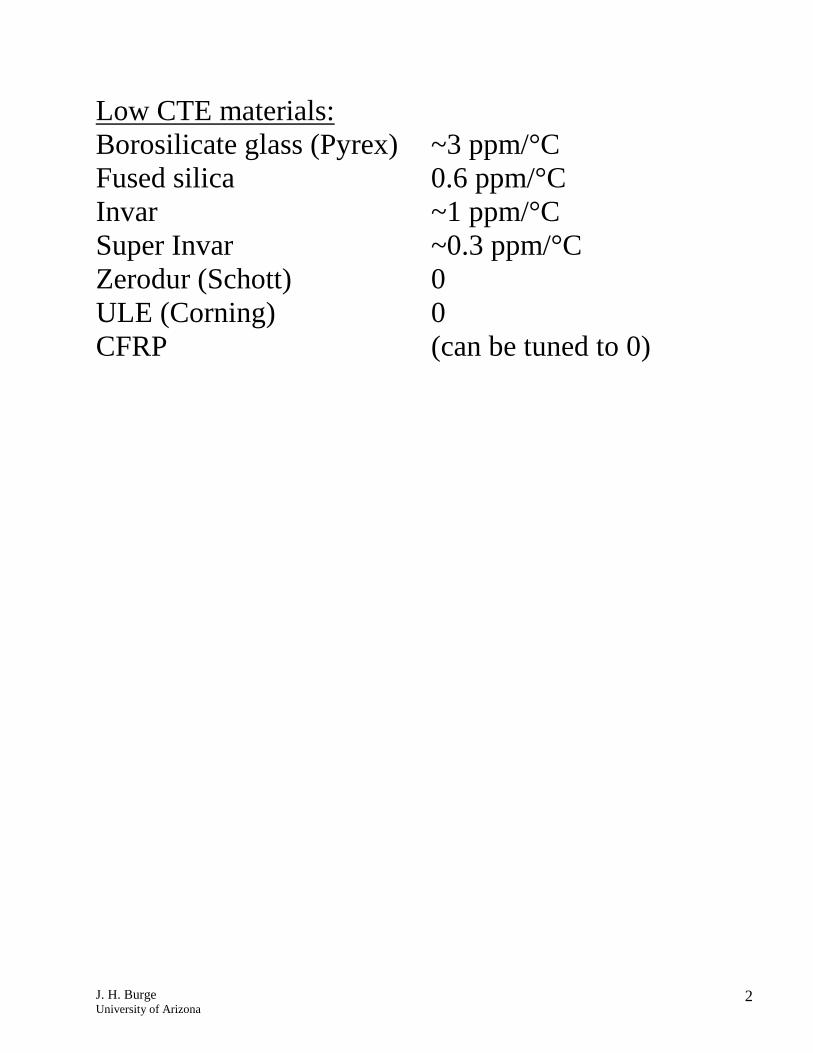
Low CTE materials: Borosilicate glass (Pyrex) ~3 ppm/°C Fused silica 0.6 ppm/°C Invar ~1 ppm/°C Super Invar ~0.3 ppm/°C Zerodur (Schott) 0 ULE (Corning) 0 CFRP (can be tuned to 0)
J. H. Burge University of Arizona
3
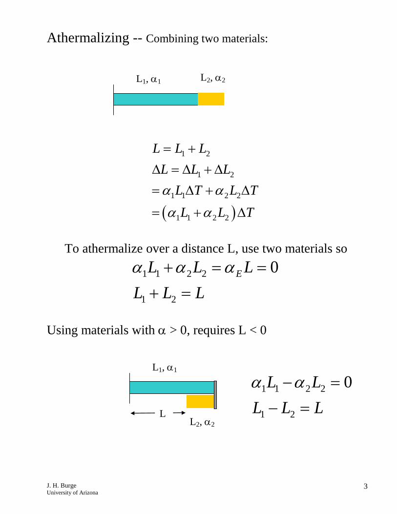
Athermalizing -- Combining two materials:
( )
1 2
1 2
1 1 2 2
1 1 2 2
L L LL L L
L T L TL L T
α αα α
= +∆ = ∆ + ∆= ∆ + ∆
= + ∆
To athermalize over a distance L, use two materials so
1 1 2 2
1 2
0EL L LL L Lα α α+ = =
+ = Using materials with α > 0, requires L < 0
L1, α1 L2, α2
L1, α1
L2, α2 L
1 1 2 2
1 2
0L LL L Lα α− =
− =
J. H. Burge University of Arizona
4
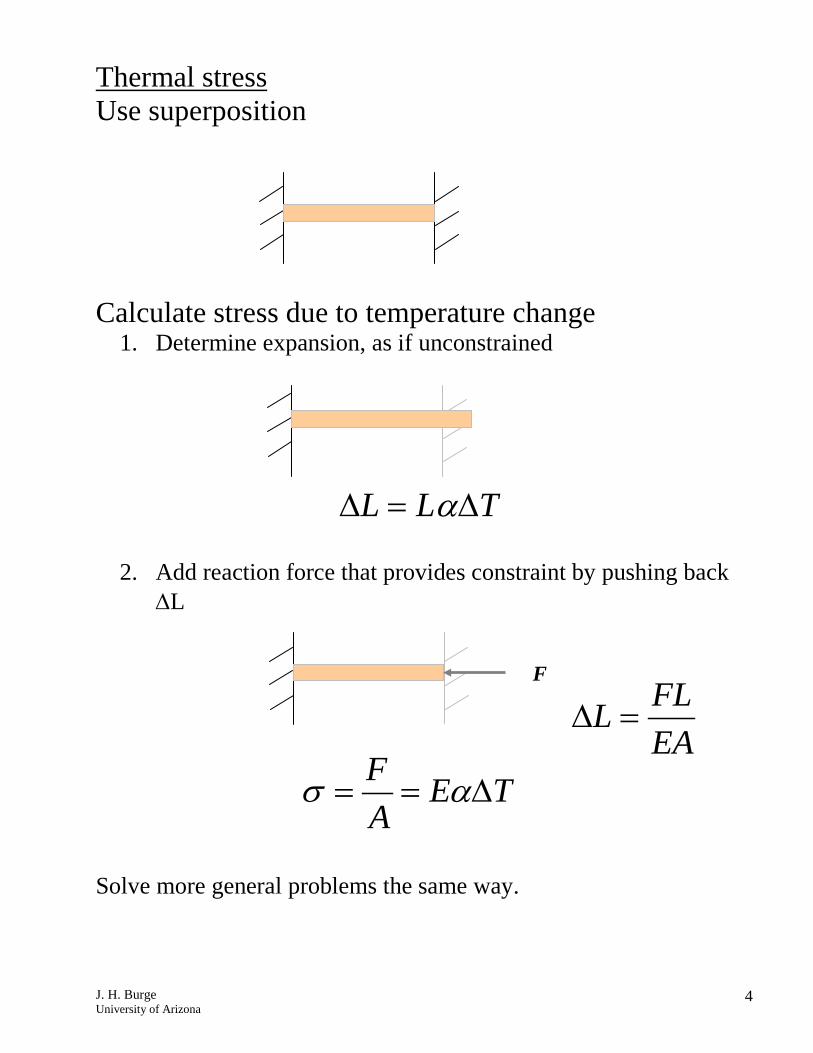
Thermal stress Use superposition Calculate stress due to temperature change
1. Determine expansion, as if unconstrained
L L Tα∆ = ∆
2. Add reaction force that provides constraint by pushing back ∆L
Solve more general problems the same way.
F FLLEA
∆ =
F E TA
σ α= = ∆
J. H. Burge University of Arizona
5
J. H. Burge 30
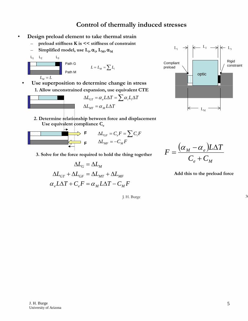
Control of thermally induced stresses
• Design preload element to take thermal strain – preload stiffness K is << stiffness of constraint– Simplified model, use Li, αi, LM, αM
FCTLFCTLLLLL
LL
MMee
MFMTGFGT
MG
−∆=+∆∆+∆=∆+∆
∆=∆
αα
L2 L3L1
LM
∑ ∆=∆=∆ TLTLL iieGT αα
optic
Rigid constraint
Compliant preload
L1 L2 L3
Path G∑== iM LLL
LLM =
2. Determine relationship between force and displacementUse equivalent compliance Ce
Path M
TLL MMT ∆=∆ α
• Use superposition to determine change in stress1. Allow unconstrained expansion, use equivalent CTE
F
F
∑==∆ FCFCL ieGF
FCL MMF −=∆( )
Me
eM
CCTLF
+∆−
=αα
3. Solve for the force required to hold the thing together
Add this to the preload force

J. H. Burge University of Arizona
6
Temperature gradients cause distortions
Gradient = 1 2T TT
y h−∂
=∂
This will cause the beam to bend in an arc, in the same way that the applied moment did. The arc length along surface 1 is longer than the arc length along surface 2 by the amount
( )1 2 1 2L L L T Tα− = − By geometry: or More generally, Integrate for deflection
T1
T2 h
L
∆θ
1
2
1 2
1
L Lh
L Th
TL R y
θ
αθ
θ α
−∆ =
∆∆ =
∆ ∂= =
∆ ∂
J. H. Burge University of Arizona
7
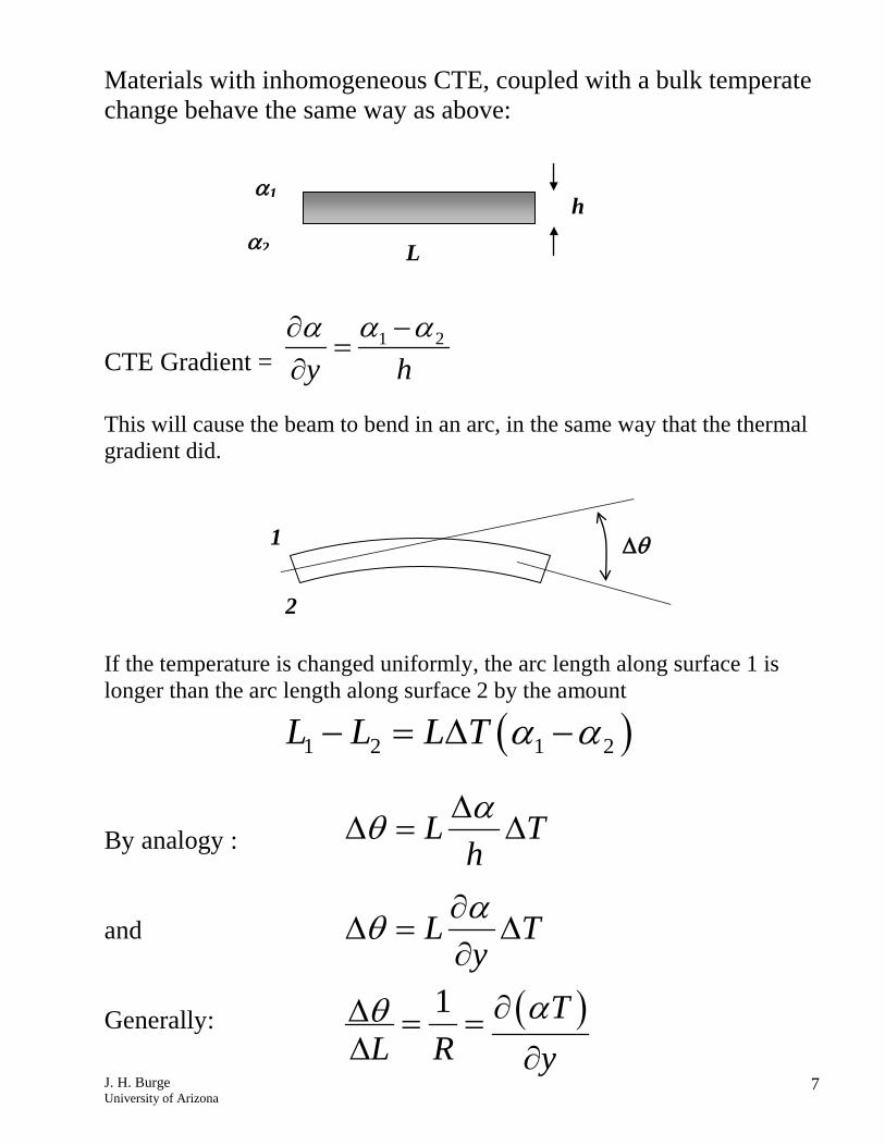
Materials with inhomogeneous CTE, coupled with a bulk temperate change behave the same way as above:
CTE Gradient = 1 2
y hα αα −∂
=∂
This will cause the beam to bend in an arc, in the same way that the thermal gradient did. If the temperature is changed uniformly, the arc length along surface 1 is longer than the arc length along surface 2 by the amount
( )1 2 1 2L L L T α α− = ∆ − By analogy : and Generally:
α1
α2 h
L
∆θ 1
2
( )1
L Th
L Ty
TL R y
αθ
αθ
αθ
∆∆ = ∆
∂∆ = ∆
∂
∂∆ = =∆ ∂
J. H. Burge University of Arizona
8
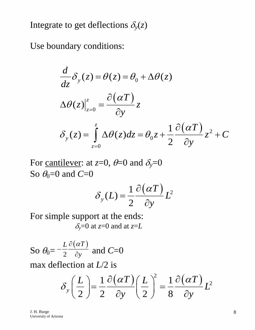
Integrate to get deflections δy(z) Use boundary conditions: For cantilever: at z=0, θ=0 and δy=0 So θ0=0 and C=0 For simple support at the ends: δy=0 at z=0 and at z=L
So θ0= ( )
2TL
yα∂
−∂ and C=0
max deflection at L/2 is
( )
( )
0
0
20
0
( ) ( ) ( )
( )
1( ) ( )2
y
z
z
z
yz
d z z zdz
Tz z
yT
z z dz z z Cy
δ θ θ θ
αθ
αδ θ θ
=
=
= = + ∆
∂∆ =
∂
∂= ∆ = + +
∂∫
( ) 21( )2y
TL L
yα
δ∂
=∂
( ) ( )221 1
2 2 2 8y
T TL L Ly y
α αδ
∂ ∂ = = ∂ ∂
J. H. Burge University of Arizona
9
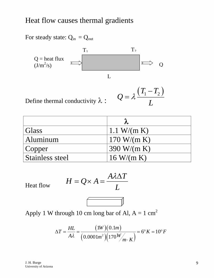
Heat flow causes thermal gradients For steady state: Qin = Qout
Define thermal conductivity λ : ( )1 2T T
QL
λ−
=
λ Glass 1.1 W/(m K) Aluminum 170 W/(m K) Copper 390 W/(m K) Stainless steel 16 W/(m K)
Heat flow A TH Q A
Lλ∆
= × = Apply 1 W through 10 cm long bar of Al, A = 1 cm2
( )( )( )( )2
1 0.16 10
0.0001 170
W mHLT K FWA m m K
λ∆ = = = ° = °
⋅
Q = heat flux (J/m2/s) Q
L
T1 T2
J. H. Burge University of Arizona
10
Steady state thermal distortion
Distortion due to temperature gradient T∇ is always
proportional to Tα∇ For a constant heat source, with power H, the thermal gradient is
proportional to HTλ
∇ ∝
So the distortion will be proportional to
αλ
This provides a figure of merit to compare sensitivity to steady state heat loading
J. H. Burge University of Arizona
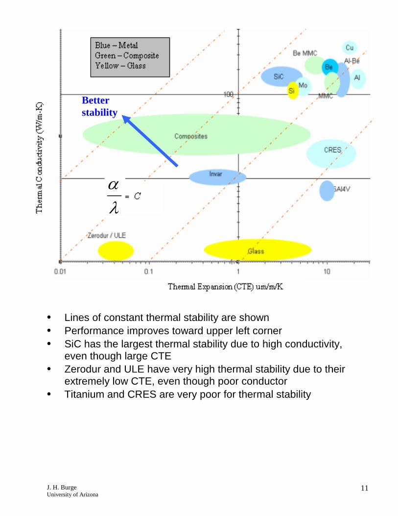
11
• Lines of constant thermal stability are shown • Performance improves toward upper left corner • SiC has the largest thermal stability due to high conductivity,
even though large CTE • Zerodur and ULE have very high thermal stability due to their
extremely low CTE, even though poor conductor • Titanium and CRES are very poor for thermal stability
αλ
Better stability
J. H. Burge University of Arizona
12
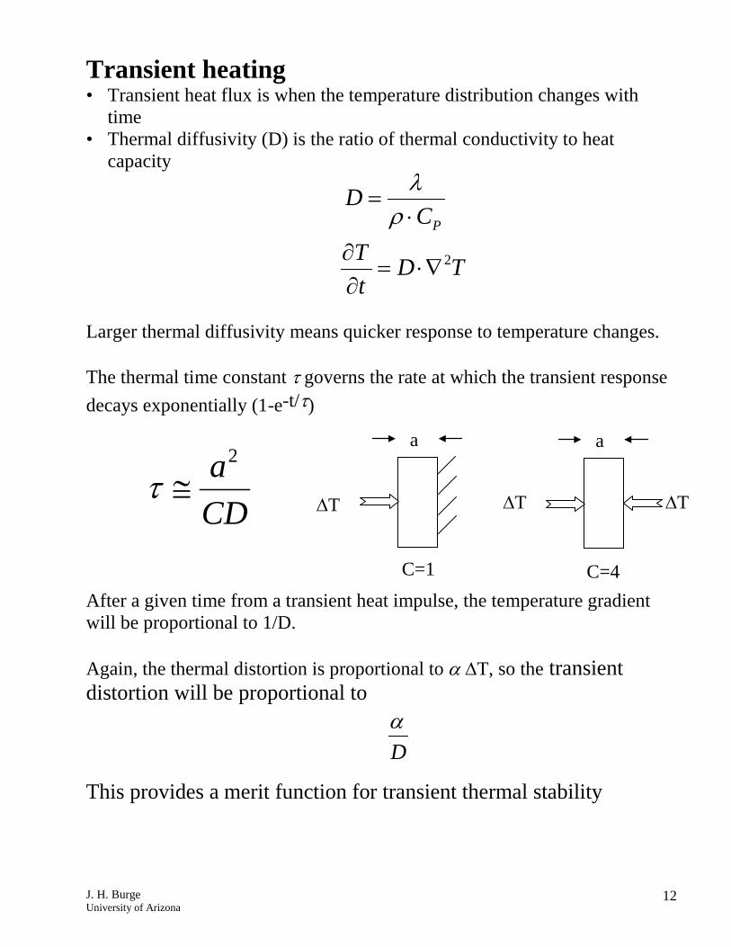
Transient heating • Transient heat flux is when the temperature distribution changes with
time • Thermal diffusivity (D) is the ratio of thermal conductivity to heat
capacity Larger thermal diffusivity means quicker response to temperature changes. The thermal time constant τ governs the rate at which the transient response decays exponentially (1-e-t/τ) After a given time from a transient heat impulse, the temperature gradient will be proportional to 1/D. Again, the thermal distortion is proportional to α ∆T, so the transient distortion will be proportional to
This provides a merit function for transient thermal stability
P
DC
λρ
=⋅
Dα
2aCD
τ ≅∆T
a
C=1
a
C=4
2T D Tt
∂= ⋅∇
∂
∆T
∆T
J. H. Burge University of Arizona
13
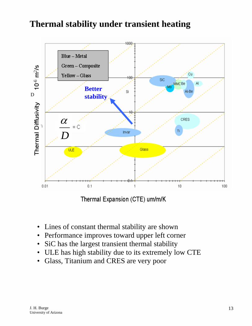
Thermal stability under transient heating
• Lines of constant thermal stability are shown • Performance improves toward upper left corner • SiC has the largest transient thermal stability • ULE has high stability due to its extremely low CTE • Glass, Titanium and CRES are very poor
Dα
D Better stability
J. H. Burge University of Arizona
14
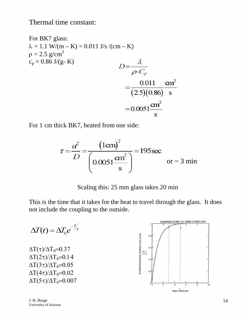
Thermal time constant: For BK7 glass: λ = 1.1 W/(m – K) = 0.011 J/s /(cm – K) ρ = 2.5 g/cm3 cp = 0.86 J/(g- K) For 1 cm thick BK7, heated from one side:
or ~ 3 min
Scaling this: 25 mm glass takes 20 min
This is the time that it takes for the heat to travel through the glass. It does not include the coupling to the outside.
∆Τ(τ)/∆Τ0=0.37 ∆Τ(2τ)/∆Τ0=0.14 ∆Τ(3τ)/∆Τ0=0.05 ∆Τ(4τ)/∆Τ0=0.02 ∆Τ(5τ)/∆Τ0=0.007
J. H. Burge University of Arizona
15
Athermal System design
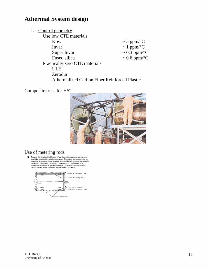
1. Control geometry Use low CTE materials Kovar ~ 5 ppm/°C Invar ~ 1 ppm/°C Super Invar ~ 0.3 ppm/°C Fused silica ~ 0.6 ppm/°C Practically zero CTE materials ULE Zerodur Athermalized Carbon Fiber Reinforced Plastic Composite truss for HST
Use of metering rods
J. H. Burge University of Arizona
16
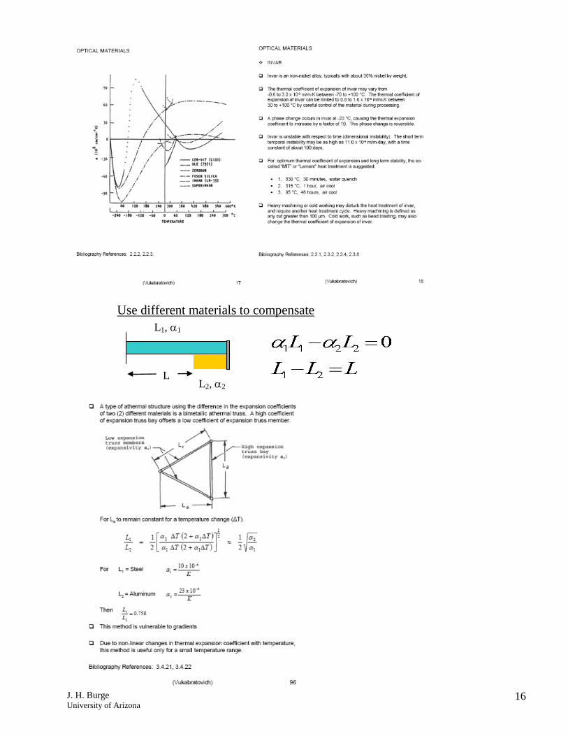
Use different materials to compensate
L1, α1
L2, α2 L
J. H. Burge University of Arizona
17
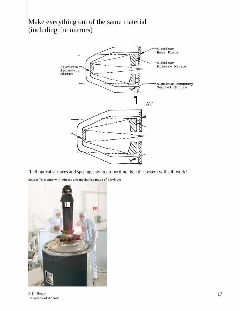
Make everything out of the same material (including the mirrors)
If all optical surfaces and spacing stay in proportion, then the system will still work! Spitzer Telescope with mirrors and mechanics made of beryllium
∆T

![;T arXiv:2004.12155v2 [hep-ph] 23 May 2020 · L;T R toSM,whichisdubbed asVLQTmodel. TheLagrangiancanbewrittenas[21] L= L SM+ LYukawa T + L gauge T; LYukawa T = i T Q i L eT R M T](https://static.fdocument.org/doc/165x107/5fc6f89706f746179e1ee992/t-arxiv200412155v2-hep-ph-23-may-2020-lt-r-tosmwhichisdubbed-asvlqtmodel.jpg)


![[Www.mathvn.com] Lt Bt Vatly12 Ltdh](https://static.fdocument.org/doc/165x107/548646195806b5d1588b4913/wwwmathvncom-lt-bt-vatly12-ltdh.jpg)