K1POO 4 Band Off Centre Fed Dipole (40-20-15-10m ) · PDF fileK1POO 4 Band Off Centre Fed...
7
K1POO 4 Band Off Centre Fed Dipole (40-20-15-10m ) 4:1 3.65m (12.0ft) 17.38m (57.0ft) 50Ω Coax Balun Transformer 1/6 5/6 K1POO OcFd Editors note:- The antenna was originally designed by Richard Formato as K1POO. However the call sign has since been re-issued to another person. Note 1 BACKGROUND FROM WINDOM TO OCFD 1927 – September; Loren Windom, W8GZ/W8ZG, was the first to reveal the Windom antenna to the radio amateur community by describing the antenna in the September issue of QST. The antenna was a half-wave in length using a single wire feeder of any length attached 0.18λ from one end providing a 500 ohms match. 1936 – November; Jim MacIntosh VS1AA (later GM3IAA), publishes “Some experimental work with aerials” in the T&R Bulletin, describing a “compromise multiband Windom” . This was a 41m long horizontal wire with a 1/3+2/3 split and used a single wire feeder. The antenna works well on the harmonically related bands (80, 40, 20 and 10m). Strictly speaking the following are not Windoms since they do not use a single feed wire. They are more accurately described as Off Centre Fed Dipoles (OCFD). 1971 - Dr. Fritz Spillner, DJ2KY, in "Die FD4-Windom-Antenne," QRV, Stuttgart, 25, December 1971, pp.13-20 describes a modified VS1AA OCFD with a 4:1 balun connected to a coaxial feeder. The Fritzel FD4 antenna becomes more popular in Europe and N. America. A shorter version FD3 for 40-10m operation is also developed. 1996 – February; Bill G0FAH, describes “Four Bands, Off Centre” in QST magazine, suggesting the use of a quarter-wave 300/450 ohms ladder line as an impedance matching transformer to enable the modified 40m-20m-10m version of VS1AA OCFD to operate on the 15m band, but this requires a switched 4:1 /1:1 balun at the end of the ladder line. 1996 - November; Richard Formato, K1POO, in “Feeding the Off Centre Dipole” ( Electronics World, November 1996) describes his theoretical study of the feed point of a shorter 40m version of the VS1AA OCFD, suggesting that the 1/3 + 2/3 split is not the best split for operating on 4 bands and concludes that the 1/6+5/6 split provides the best overall 4-band performance. 1997 - June; Dale Gaudier, M0AOP/K4DG, in the RSGB Technical Topics section of Radio Communication describes his experiments with the K1POO design, explaining that a choke is required next to the 4:1 balun for the antenna to resonate on its fundamental frequency of 7MHz. The choke (aka dirty balun) has 5 ½ turns of RG-8X coax with a diameter of 24cm. The antenna’s SWR on 40m, 20, 15m and 10m is less than 2:1 and the antenna is fairly broad-banded. 2001-March; Zack Lau (W1VT), in his article “Making the Off-Center Fed Dipoles Work”, after modelling the OCFD concludes that a line isolator ( choke ) is required for optimum operation of the antenna. 2012 Ro’s (M0RZF) experiments and measurements using VNA concludes that the K1POO OCFD benefits from use of a choke balun. However…. 1949 -summer; G. E. "Buck" Rogers Sr; (K4ABT) overhears Jack Kennamer, (W4YPC) describing a Windom antenna on all the HF bands without the need for an antenna tuner. He does this by using a 9-turn coil of the coax (aka dirty balun) at the feed point to prevent RF being re-radiated off the coax shield. Buck’s interest in this antenna is born. 1958 - Buck K4ABT reads about Gillette Guanella “current” type balun and Thomas O’Meara’s papers, “Analysis and Synthesis with the Complete Equivalent Circuit for the-Band Transformer”,which leads to some design changes being made to Buck’s version of the Windom antenna. 1968 - Lew McCoy (W1ICP) introduces Buck to a new balun design, which, with a 1/3 + 2/3 split, produces a Buxcomm TM Windom with an 8 band HF operating range. Buck (K4ABT) describes the new Buxcomm TM matching Device as an “integrated Balun & center insulator”. There are two versions of the antenna covering 80m to 6m” and 40m to 6m”. These can be supplied with one of three Buxcomm baluns (4:1, 5:1, 6:1 ) to accommodate working heights between 25ft (8m) -75ft.(22.8m). ref http://www.buxcomm.com/windom.htm But if the choke moves further down the coax feeder we end up with a CAROLINA WINDOM ® but that’s another story……. Graphics by G8ODE June 2012 iss 1.3 Note 1. Dale Gaudier, M0AOP/K4DG, Zack Lau (W1VT) , Jack Kennamer, (W4YPC) and Lew McCoy (W1ICP) and M0RZF suggest a choke or choke-balun improves operation.
-
Upload
phamnguyet -
Category
Documents
-
view
252 -
download
0
Transcript of K1POO 4 Band Off Centre Fed Dipole (40-20-15-10m ) · PDF fileK1POO 4 Band Off Centre Fed...
K1POO 4 Band Off Centre Fed Dipole
(40-20-15-10m )
4:1
3.65m
(12.0ft)
17.38m
(57.0ft)
50Ω
Coax
Balun
Transformer
1/6 5/6
K1POO OcFd
Editors note:-
The antenna was originally designed by Richard
Formato as K1POO. However the call sign has
since been re-issued to another person.
Note 1
BACKGROUND FROM WINDOM TO OCFD
1927 – September; Loren Windom, W8GZ/W8ZG, was the first to reveal the Windom antenna to the radio amateur community by describing the antenna in the
September issue of QST. The antenna was a half-wave in length using a single wire feeder of any length attached 0.18λ from one end providing a 500 ohms
match.
1936 – November; Jim MacIntosh VS1AA (later GM3IAA), publishes “Some experimental work with aerials” in the T&R Bulletin, describing a “compromise multiband
Windom” . This was a 41m long horizontal wire with a 1/3+2/3 split and used a single wire feeder. The antenna works well on the harmonically related bands (80, 40, 20
and 10m).
Strictly speaking the following are not Windoms since they do not use a single feed wire. They are more accurately described as Off Centre Fed Dipoles (OCFD).
1971 - Dr. Fritz Spillner, DJ2KY, in "Die FD4-Windom-Antenne," QRV, Stuttgart, 25, December 1971, pp.13-20 describes a modified VS1AA OCFD with a 4:1 balun
connected to a coaxial feeder. The Fritzel FD4 antenna becomes more popular in Europe and N. America. A shorter version FD3 for 40-10m operation is also developed.
1996 – February; Bill G0FAH, describes “Four Bands, Off Centre” in QST magazine, suggesting the use of a quarter-wave 300/450 ohms ladder line as an impedance
matching transformer to enable the modified 40m-20m-10m version of VS1AA OCFD to operate on the 15m band, but this requires a switched 4:1 /1:1 balun at the end of
the ladder line.
1996 - November; Richard Formato, K1POO, in “Feeding the Off Centre Dipole” ( Electronics World, November 1996) describes his theoretical study of the feed point of a
shorter 40m version of the VS1AA OCFD, suggesting that the 1/3 + 2/3 split is not the best split for operating on 4 bands and concludes that the 1/6+5/6 split provides the
best overall 4-band performance.
1997 - June; Dale Gaudier, M0AOP/K4DG, in the RSGB Technical Topics section of Radio Communication describes his experiments with the K1POO design, explaining
that a choke is required next to the 4:1 balun for the antenna to resonate on its fundamental frequency of 7MHz. The choke (aka dirty balun) has 5 ½ turns of RG-8X coax
with a diameter of 24cm. The antenna’s SWR on 40m, 20, 15m and 10m is less than 2:1 and the antenna is fairly broad-banded.
2001-March; Zack Lau (W1VT), in his article “Making the Off-Center Fed Dipoles Work”, after modelling the OCFD concludes that a line isolator ( choke ) is required for
optimum operation of the antenna.
2012 Ro’s (M0RZF) experiments and measurements using VNA concludes that the K1POO OCFD benefits from use of a choke balun.
However….
1949 -summer; G. E. "Buck" Rogers Sr; (K4ABT) overhears Jack Kennamer, (W4YPC) describing a Windom antenna on all the HF bands without the need for an
antenna tuner. He does this by using a 9-turn coil of the coax (aka dirty balun) at the feed point to prevent RF being re-radiated off the coax shield. Buck’s interest in this
antenna is born.
1958 - Buck K4ABT reads about Gillette Guanella “current” type balun and Thomas O’Meara’s papers, “Analysis and Synthesis with the Complete Equivalent Circuit for
the-Band Transformer”,which leads to some design changes being made to Buck’s version of the Windom antenna.
1968 - Lew McCoy (W1ICP) introduces Buck to a new balun design, which, with a 1/3 + 2/3 split, produces a Buxcomm TM Windom with an 8 band HF operating
range. Buck (K4ABT) describes the new Buxcomm TM matching Device as an “integrated Balun & center insulator”. There are two versions of the antenna covering 80m to
6m” and 40m to 6m”. These can be supplied with one of three Buxcomm baluns (4:1, 5:1, 6:1 ) to accommodate working heights between 25ft (8m) -75ft.(22.8m).
ref http://www.buxcomm.com/windom.htm
But if the choke moves further down the coax feeder we end up with a CAROLINA WINDOM ® but that’s another story…….
Graphics by G8ODE June 2012 iss 1.3
Note 1. Dale Gaudier, M0AOP/K4DG, Zack Lau (W1VT) , Jack Kennamer, (W4YPC) and Lew McCoy (W1ICP) and M0RZF suggest a choke or choke-balun improves operation.
The characteristics of the two feed-point positions. 1. The more common split of 1/3+2/3 uses a 6:1 or 4:1 balun to 50Ω coax to the shack. This suggests that the antenna’s feed point
is either 200Ω or 300Ω. In fact it’s more complicated than this as the impedance depends on the height above real ground in
wavelengths (see later graph). A typical antenna using this split is the FD3 3-band OCFD.
2. However, the 1/3+2/3 split creates a high impedance on the 15m band i.e. the current is zero at this position. G0FAH proposed
using a 1/4λ transmission line transformer section made from 300Ω or 450Ω twin feeder to overcome this problem. But this requires
a dual ratio current balun. For 15m operation the 1:1 ratio is used and the 4:1 ratio on 40m, 20m & 10m bands.
3. K1POO studied the 40m OCFD using computer models and in the May and October, 1996 issues of QST, suggested a 0.174 +
0.826 (3.65m+17.38m) split. This split allows the OCFD to be operated as a 4 band antenna as the SWR on the 40m band is less
than 3.6:1 and less than 1.4:1 on the 20,15,10m bands
BACKGROUND TO THE DEVELOPMENT OF THE K1POO ANTENNA
K1POO
40-20-15-10m
7.05MHz
14.15MHz
21.2Mz
28.2MHz
Cu
rre
nt
20 40 60 80 1000
G0FAH
40-20-10m & 15m
FD3
40-20-10m
% of overall length
17.4 33.3
K1POO 4 Band Off Centre Fed Dipole
(40-20-15-10m )
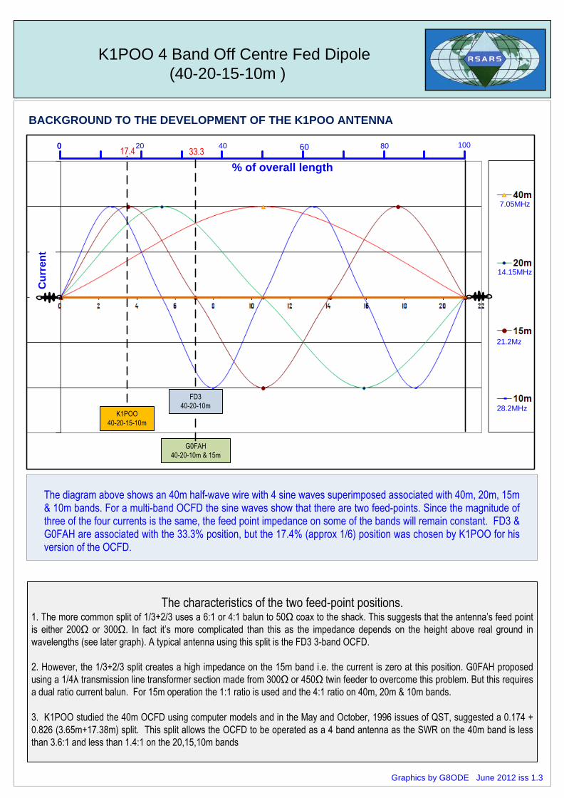
The diagram above shows an 40m half-wave wire with 4 sine waves superimposed associated with 40m, 20m, 15m & 10m bands. For a multi-band OCFD the sine waves show that there are two feed-points. Since the magnitude of three of the four currents is the same, the feed point impedance on some of the bands will remain constant. FD3 & G0FAH are associated with the 33.3% position, but the 17.4% (approx 1/6) position was chosen by K1POO for his version of the OCFD.
Graphics by G8ODE June 2012 iss 1.3
K1POO 4 Band Off Centre Fed Dipole
(40-20-15-10m )
40m 20m 15m 10m
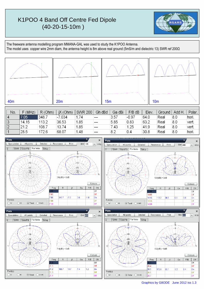
The freeware antenna modelling program MMANA-GAL was used to study the K1POO Antenna.
The model uses copper wire 2mm diam, the antenna height is 8m above real ground (5mS/m and dielectric 13) SWR ref 200Ω
Graphics by G8ODE June 2012 iss 1.3
K1POO 4 Band Off Centre Fed Dipole
(40-20-15-10m )
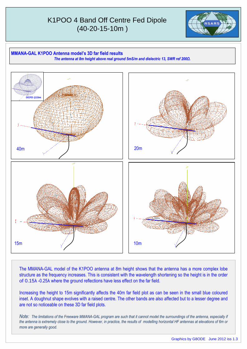
MMANA-GAL K1POO Antenna model’s 3D far field resultsThe antenna at 8m height above real ground 5mS/m and dielectric 13, SWR ref 200Ω.
The MMANA-GAL model of the K1POO antenna at 8m height shows that the antenna has a more complex lobe
structure as the frequency increases. This is consistent with the wavelength shortening so the height is in the order
of 0.15λ -0.25λ where the ground reflections have less effect on the far field.
Increasing the height to 15m significantly affects the 40m far field plot as can be seen in the small blue coloured
inset. A doughnut shape evolves with a raised centre. The other bands are also affected but to a lesser degree and
are not so noticeable on these 3D far field plots.
Note: The limitations of the Freeware MMANA-GAL program are such that it cannot model the surroundings of the antenna, especially if
the antenna is extremely close to the ground. However, in practice, the results of modelling horizontal HF antennas at elevations of 6m or
more are generally good.
40m 20m
15m 10m
OCFD @15m
Graphics by G8ODE June 2012 iss 1.3
K1POO 4 Band Off Centre Fed Dipole
(40-20-15-10m )
MMANA-GAL K1POO Off Centre Dipole model
(overall length 21.04m)
Short Long
Source 50Ω
via
4:1 current balun
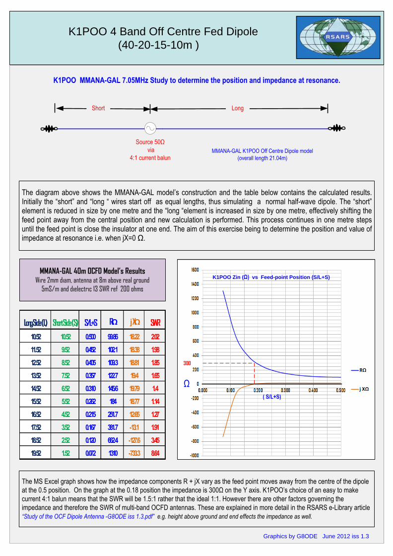
K1POO MMANA-GAL 7.05MHz Study to determine the position and impedance at resonance.
The diagram above shows the MMANA-GAL model’s construction and the table below contains the calculated results. Initially the “short” and “long “ wires start off as equal lengths, thus simulating a normal half-wave dipole. The “short” element is reduced in size by one metre and the “long “element is increased in size by one metre, effectively shifting the feed point away from the central position and new calculation is performed. This process continues in one metre steps until the feed point is close the insulator at one end. The aim of this exercise being to determine the position and value of impedance at resonance i.e. when jX=0 Ω.
The MS Excel graph shows how the impedance components R + jX vary as the feed point moves away from the centre of the dipole
at the 0.5 position. On the graph at the 0.18 position the impedance is 300Ω on the Y axis. K1POO’s choice of an easy to make
current 4:1 balun means that the SWR will be 1.5:1 rather that the ideal 1:1. However there are other factors governing the
impedance and therefore the SWR of multi-band OCFD antennas. These are explained in more detail in the RSARS e-Library article
“Study of the OCF Dipole Antenna -G8ODE iss 1.3.pdf” e.g. height above ground and end effects the impedance as well.
MMANA-GAL 40m OCFD Model’s ResultsWire 2mm diam, antenna at 8m above real ground
5mS/m and dielectric 13 SWR ref 200 ohms
Long Side (L) Short Side (S) S/L+S RΩ j XΩ SWR
10.52 10.52 0.500 99.86 18.22 2.02
11.52 9.52 0.452 102.1 18.38 1.98
12.52 8.52 0.405 109.3 18.81 1.85
13.52 7.52 0.357 122.7 19.4 1.65
14.52 6.52 0.310 145.6 19.79 1.4
15.52 5.52 0.262 184 18.77 1.14
16.52 4.52 0.215 251.7 12.65 1.27
17.52 3.52 0.167 381.7 -13.1 1.91
18.52 2.52 0.120 662.4 -127.6 3.45
19.52 1.52 0.072 1310 -733.3 8.64
K1POO Zin (Ω) vs Feed-point Position (S/L+S)
Ω
( S/L+S)
300
Graphics by G8ODE June 2012 iss 1.3
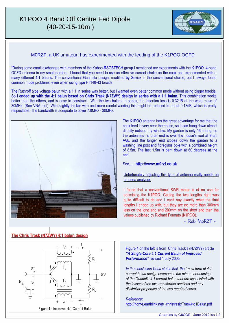
“During some email exchanges with members of the Yahoo-RSGBTECH group I mentioned my experiments with the K1POO 4-band OCFD antenna in my small garden. I found that you need to use an effective current choke on the coax and experimented with a many different 4:1 baluns. The conventional Guanella design, modified by Sevick is the conventional choice, but I always found common mode problems, even when using type FT140-43 toroids.
The Ruthroff type voltage balun with a 1:1 in series was better, but I wanted even better common mode without using bigger toroids. So I ended up with the 4:1 balun based on Chris Trask (N7ZWY) design in series with a 1:1 balun. This combination works better than the others, and is easy to construct. With the two baluns in series, the insertion loss is 0.32dB at the worst case of 30MHz. (See VNA plot). With slightly thicker wire and more careful winding this might be reduced to about 0.13dB, which is pretty respectable. The bandwidth is adequate to cover 7.0MHz - 30MHz.
The K1POO antenna has the great advantage for me that the coax feed is very near the house, so it can hang down almost directly outside my window. My garden is only 16m long, so the antenna’s shorter end is over the house’s roof at 9.5m AGL and the longer end slopes down the garden to a washing line post and fibreglass pole with a combined height of 8.5m. The last 1.5m is bent down at 60 degrees at the end.
See…. http://www.m0rzf.co.uk
Unfortunately adjusting this type of antenna really needs an
antenna analyser.
I found that a conventional SWR meter is of no use for
optimising the K1POO. Getting the two lengths right was
quite difficult to do and I can't say exactly what the final
lengths I ended up with, but they are no more than 300mm
less on the long end and 200mm on the short end than the
values published by Richard Formato (K1POO).
~ Rob M0RZF ~
K1POO 4 Band Off Centre Fed Dipole
(40-20-15-10m )
Graphics by G8ODE June 2012 iss 1.3
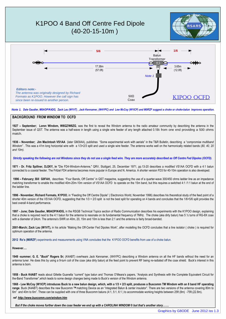
Figure 4 on the left is from Chris Trask’s (N7ZWY) article
“A Single-Core 4:1 Current Balun of Improved
Performance” revised 1 July 2005
In the conclusion Chris states that the “ new form of 4:1
current balun design overcomes the minor shortcomings
of the Guanella 4:1 current balun that are associated with
the losses of the two transformer sections and any
dissimilar properties of the two required cores.
Reference:
http://home.earthlink.net/~christrask/Trask4to1Balun.pdf
M0RZF, a UK amateur, has experimented with the feeding of the K1POO OCFD
The Chris Trask (N7ZWY) 4:1 balun design
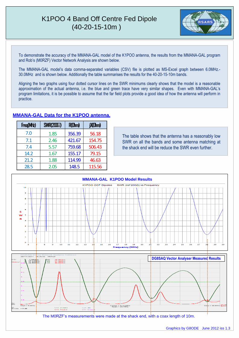
To demonstrate the accuracy of the MMANA-GAL model of the K1POO antenna, the results from the MMANA-GAL program and Rob’s (M0RZF) Vector Network Analysis are shown below.
The MMANA-GAL model’s data comma-separated variables (CSV) file is plotted as MS-Excel graph between 6.0MHz.- 30.0MHz and is shown below. Additionally the table summarises the results for the 40-20-15-10m bands.
Aligning the two graphs using four dotted cursor lines on the SWR minimums clearly shows that the model is a reasonable approximation of the actual antenna, i.e. the blue and green trace have very similar shapes. Even with MMANA-GAL’s program limitations, it is be possible to assume that the far field plots provide a good idea of how the antenna will perform in practice.
K1POO 4 Band Off Centre Fed Dipole
(40-20-15-10m )
Freq(MHz) SWR(200Ω) R(Ohm) jX(Ohm)
7.0 1.85 356.39 56.187.1 2.46 421.67 154.757.4 5.57 759.68 506.43
14.2 1.67 155.17 79.1521.2 1.88 114.99 46.6328.5 2.05 148.5 115.56
MMANA-GAL K1POO Model Results
DG8SAQ Vector Analyser Measured Results
The M0RZF’s measurements were made at the shack end, with a coax length of 10m.
MMANA-GAL Data for the K1POO antenna.
Graphics by G8ODE June 2012 iss 1.3
The table shows that the antenna has a reasonably low
SWR on all the bands and some antenna matching at
the shack end will be reduce the SWR even further.