Dipole Antennas - NPTEL · Folded Dipole Antenna The impedance of the N fold folded dipole is N2...
24
Prof. Girish Kumar Electrical Engineering Department, IIT Bombay [email protected] (022) 2576 7436 Dipole Antennas
Transcript of Dipole Antennas - NPTEL · Folded Dipole Antenna The impedance of the N fold folded dipole is N2...

Prof. Girish KumarElectrical Engineering Department, IIT Bombay
(022) 2576 7436
Dipole Antennas
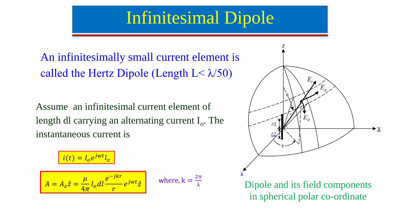
Infinitesimal Dipole
An infinitesimally small current element is
called the Hertz Dipole (Length L< λ/50)
Dipole and its field components
in spherical polar co-ordinate
𝐴 = 𝐴𝑧 𝑧 =𝜇
4𝜋𝐼𝑜𝑑𝑙
𝑒−𝑗𝑘𝑟
𝑟𝑒𝑗𝑤𝑡 𝑧
𝑖(𝑡) = 𝐼𝑜𝑒𝑗𝑤𝑡 𝑖𝑧
where, k =2π
λ
Assume an infinitesimal current element of
length dl carrying an alternating current Io. The
instantaneous current is
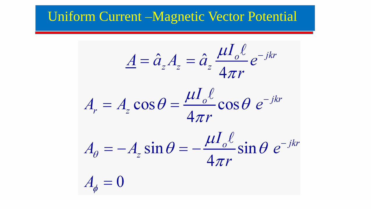
Uniform Current –Magnetic Vector Potential
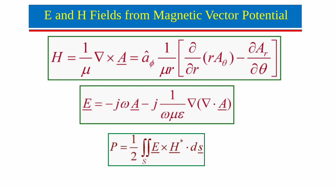
E and H Fields from Magnetic Vector Potential
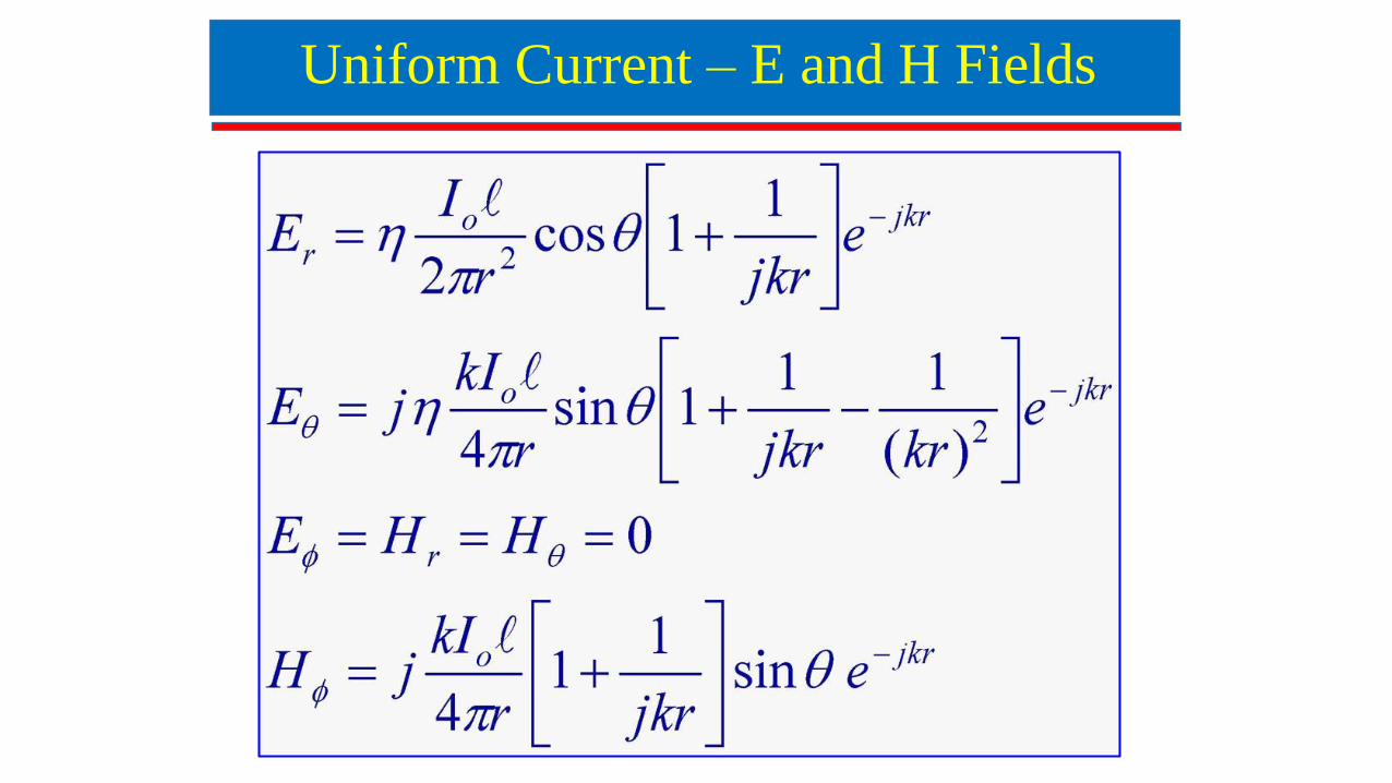
Uniform Current – E and H Fields
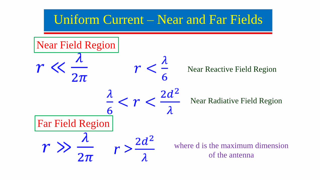
Uniform Current – Near and Far Fields
Near Field Region
Far Field Region
Near Reactive Field Region
Near Radiative Field Region
r > where d is the maximum dimension
of the antenna
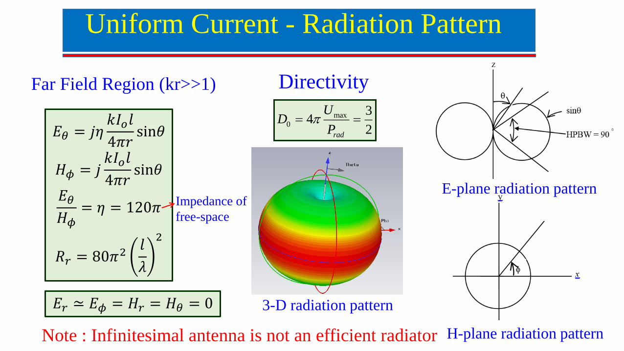
Far Field Region (kr>>1)
Uniform Current - Radiation Pattern
max
0
34
2rad
UD
P
Directivity
E-plane radiation pattern
H-plane radiation pattern
3-D radiation pattern
𝐸𝜃 = 𝑗𝜂𝑘𝐼𝑜𝑙
4𝜋𝑟sin𝜃
𝐻𝜙 = 𝑗𝑘𝐼𝑜𝑙
4𝜋𝑟sin𝜃
𝐸𝜃
𝐻𝜙= 𝜂 = 120𝜋
𝑅𝑟 = 80𝜋2𝑙
𝜆
2
𝐸𝑟 ≃ 𝐸𝜙 = 𝐻𝑟 = 𝐻𝜃 = 0
Note : Infinitesimal antenna is not an efficient radiator
Impedance of
free-space
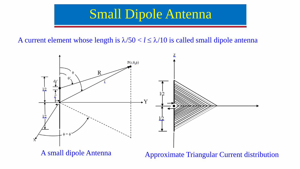
Small Dipole Antenna
A current element whose length is /50 < l /10 is called small dipole antenna
A small dipole Antenna Approximate Triangular Current distribution
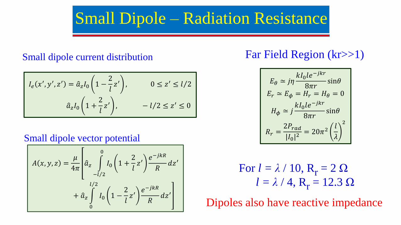
Far Field Region (kr>>1)
Small Dipole – Radiation Resistance
Small dipole current distribution
Small dipole vector potential
𝐼𝑒 𝑥′, 𝑦′, 𝑧′ = 𝑎𝑧𝐼0 1 −2
𝑙𝑧′ , 0 ≤ 𝑧′ ≤ 𝑙 2
𝑎𝑧𝐼0 1 +2
𝑙𝑧′ , − 𝑙 2 ≤ 𝑧′ ≤ 0
𝐴 𝑥, 𝑦, 𝑧 =𝜇
4𝜋 𝑎𝑧
− 𝑙 2
0
𝐼0 1 +2
𝑙𝑧′
𝑒−𝑗𝑘𝑅
𝑅𝑑𝑧′
+ 𝑎𝑧
0
𝑙 2
𝐼0 1 −2
𝑙𝑧′
𝑒−𝑗𝑘𝑅
𝑅𝑑𝑧′
𝐸𝜃 ≃ 𝑗𝜂𝑘𝐼0𝑙𝑒
−𝑗𝑘𝑟
8𝜋𝑟sin𝜃
𝐸𝑟 ≃ 𝐸𝜙 = 𝐻𝑟 = 𝐻𝜃 = 0
𝐻𝜙 ≃ 𝑗𝑘𝐼0𝑙𝑒
−𝑗𝑘𝑟
8𝜋𝑟sin𝜃
𝑅𝑟 =2𝑃𝑟𝑎𝑑
|𝐼0|2 = 20𝜋2
𝑙
𝜆
2
For l = λ / 10, Rr = 2 Ω
l = λ / 4, Rr = 12.3 Ω
Dipoles also have reactive impedance
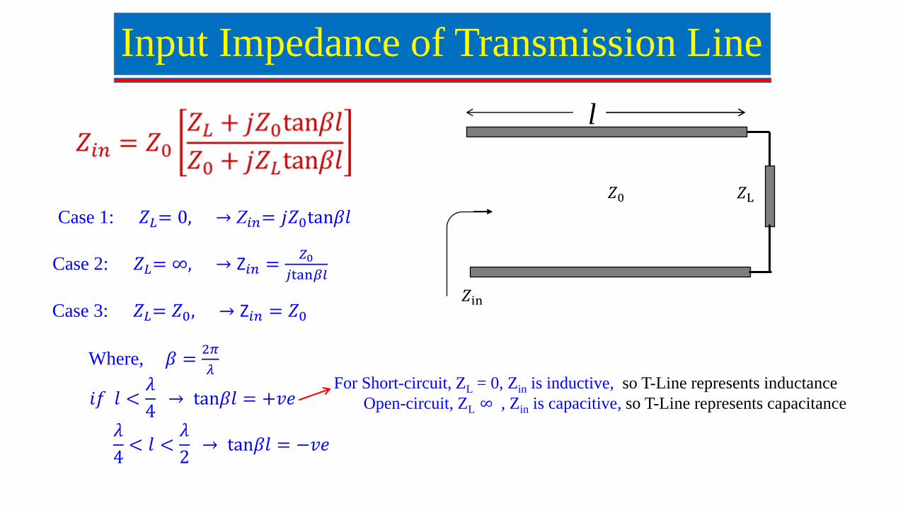
Input Impedance of Transmission Line
Case 1: 𝑍𝐿= 0, → Z𝑖𝑛= 𝑗𝑍0tan𝛽𝑙
Case 2: 𝑍𝐿= ∞, → Z𝑖𝑛 =𝑍0
𝑗tan𝛽𝑙
Case 3: 𝑍𝐿= 𝑍0, → Z𝑖𝑛 = 𝑍0
Where, 𝛽 =2𝜋
𝜆
𝑖𝑓 𝑙 <𝜆
4→ tan𝛽𝑙 = +𝑣𝑒
𝜆
4< 𝑙 <
𝜆
2→ tan𝛽𝑙 = −𝑣𝑒
𝑍0 𝑍L
𝑍in
l
For Short-circuit, ZL = 0, Zin is inductive, so T-Line represents inductance
Open-circuit, ZL = , Zin is capacitive, so T-Line represents capacitance
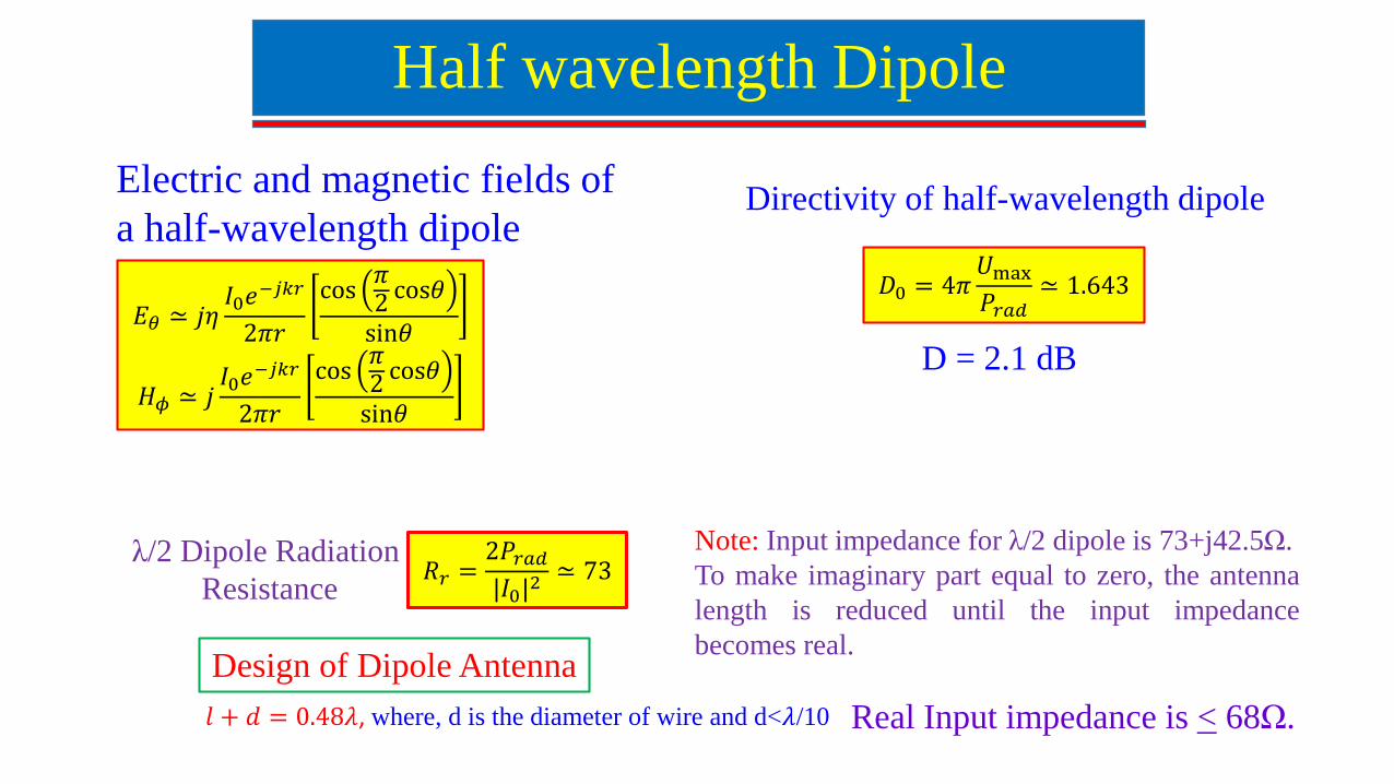
Half wavelength Dipole
Directivity of half-wavelength dipoleElectric and magnetic fields of
a half-wavelength dipole
Note: Input impedance for λ/2 dipole is 73+j42.5Ω.
To make imaginary part equal to zero, the antenna
length is reduced until the input impedance
becomes real.
𝑙 + 𝑑 = 0.48𝜆, where, d is the diameter of wire and d<𝜆/10
𝐸𝜃 ≃ 𝑗𝜂𝐼0𝑒
−𝑗𝑘𝑟
2𝜋𝑟
cos𝜋2 cos𝜃
sin𝜃
𝐻𝜙 ≃ 𝑗𝐼0𝑒
−𝑗𝑘𝑟
2𝜋𝑟
cos𝜋2 cos𝜃
sin𝜃
𝑅𝑟 =2𝑃𝑟𝑎𝑑
|𝐼0|2 ≃ 73
𝐷0 = 4𝜋𝑈max
𝑃𝑟𝑎𝑑≃ 1.643
D = 2.1 dB
λ/2 Dipole Radiation
Resistance
Design of Dipole Antenna
Real Input impedance is < 68Ω.

Current Distribution of Dipole Antenna for Different Lengths
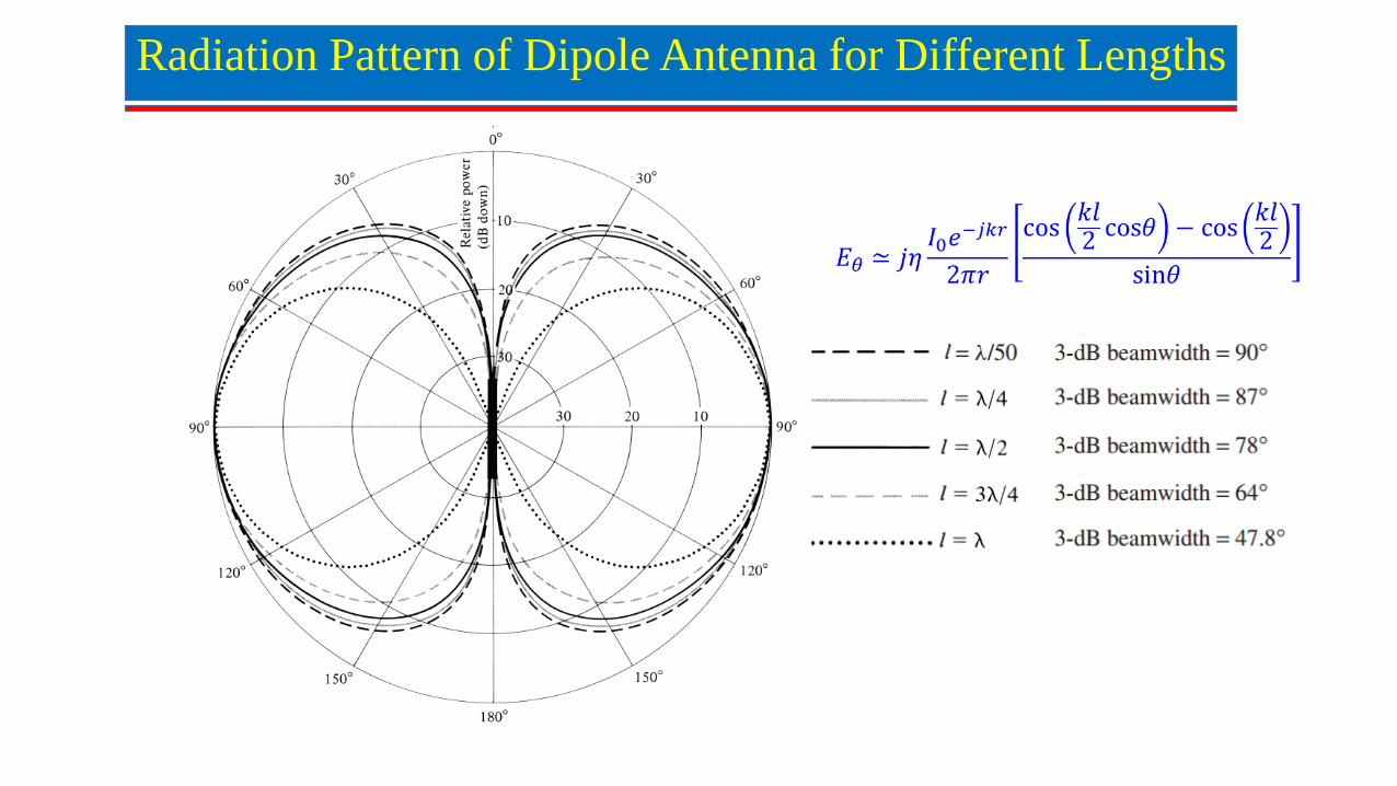
Radiation Pattern of Dipole Antenna for Different Lengths
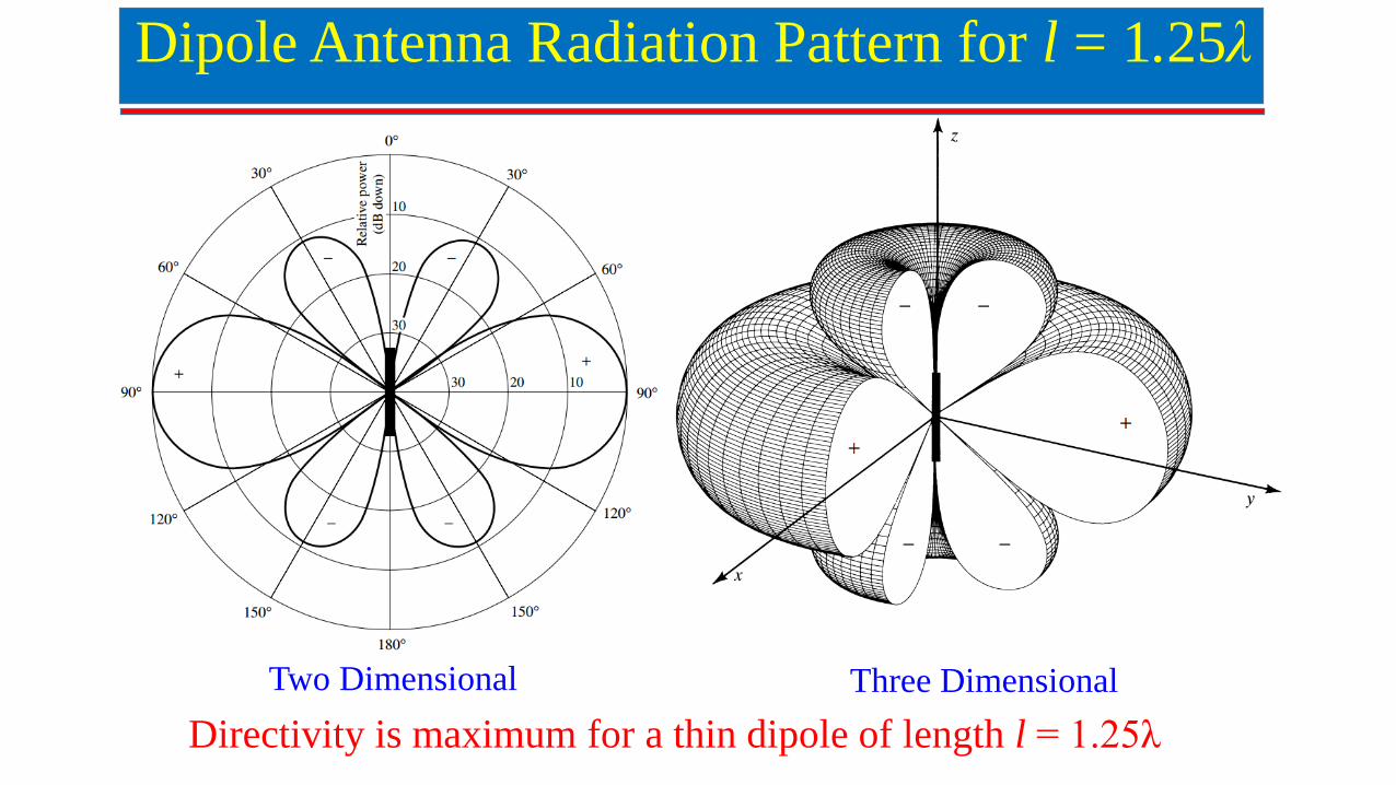
Dipole Antenna Radiation Pattern for l = 1.25λ
Two Dimensional Three Dimensional
Directivity is maximum for a thin dipole of length l = 1.25λ
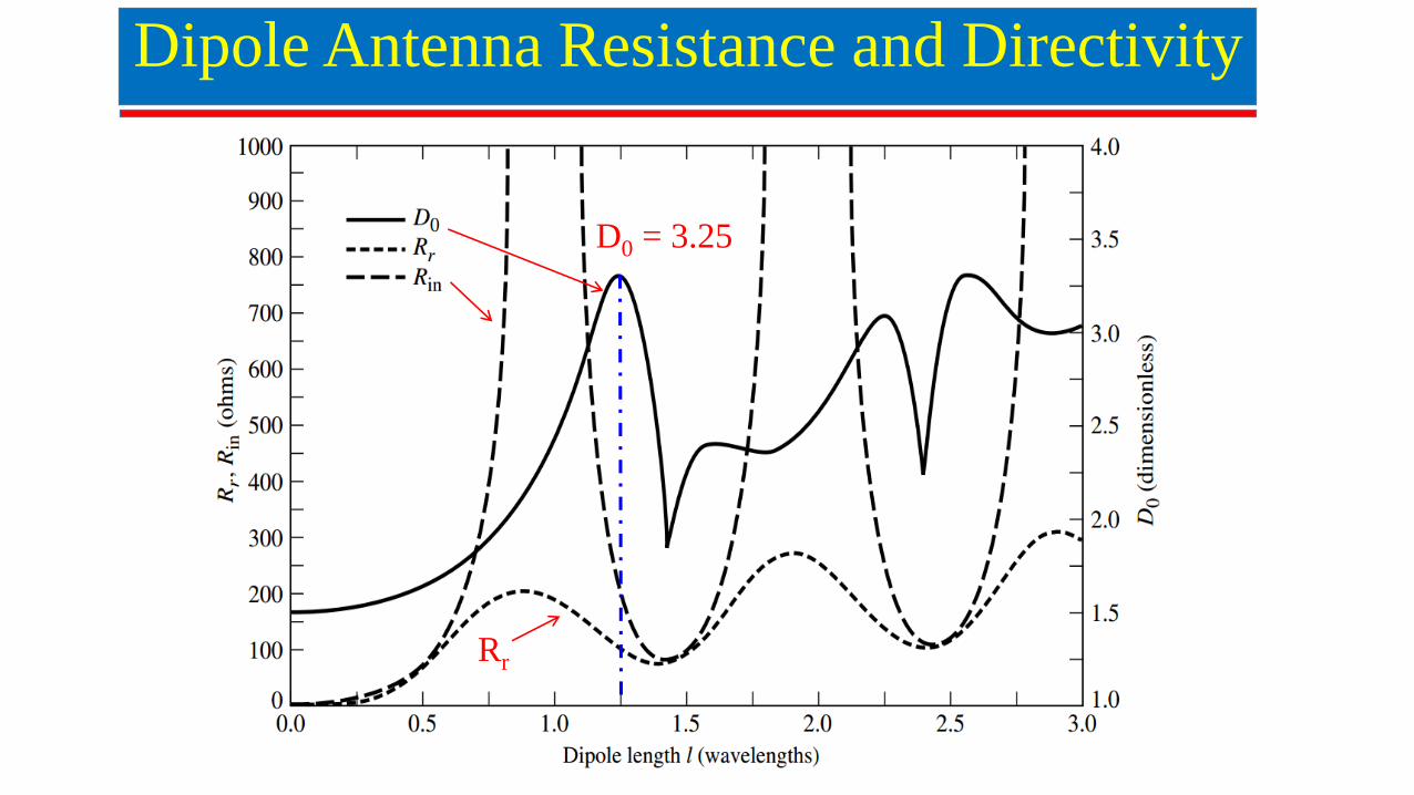
Dipole Antenna Resistance and Directivity
D0 = 3.25
Rr
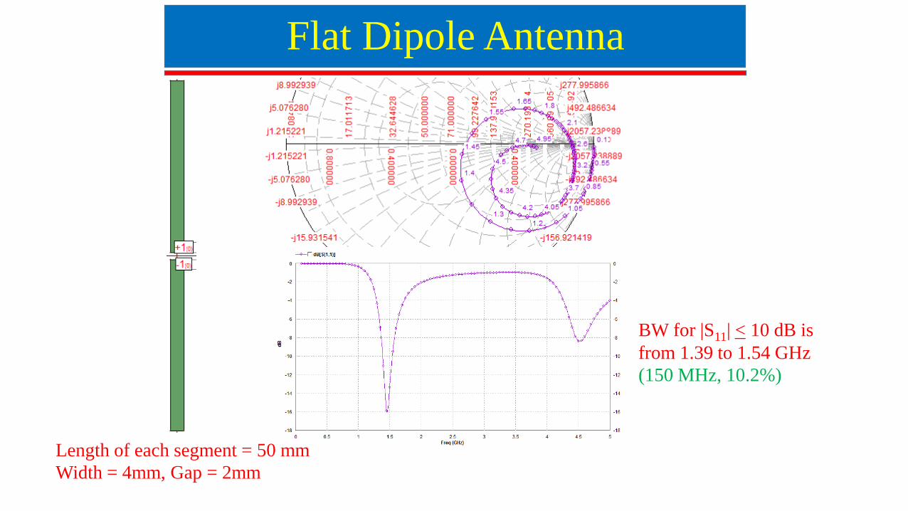
Flat Dipole Antenna
Length of each segment = 50 mm
Width = 4mm, Gap = 2mm
BW for |S11| < 10 dB is
from 1.39 to 1.54 GHz
(150 MHz, 10.2%)
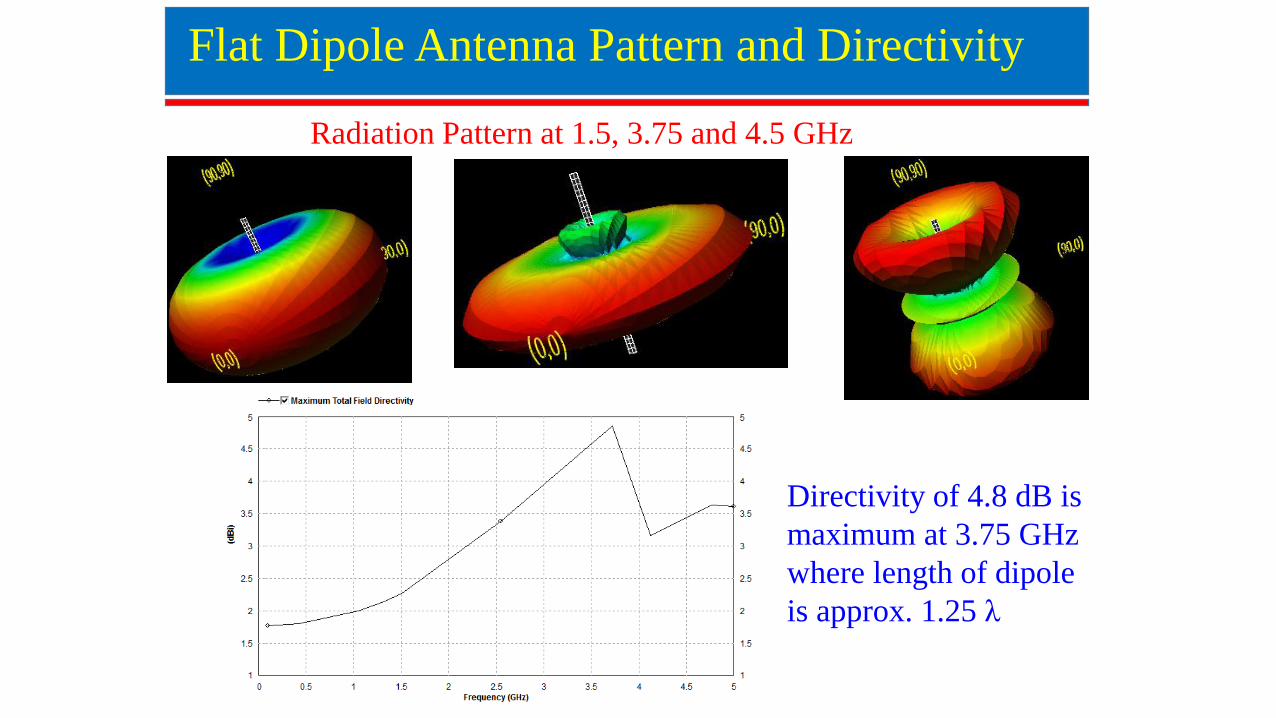
Flat Dipole Antenna Pattern and Directivity
Directivity of 4.8 dB is
maximum at 3.75 GHz
where length of dipole
is approx. 1.25 λ
Radiation Pattern at 1.5, 3.75 and 4.5 GHz
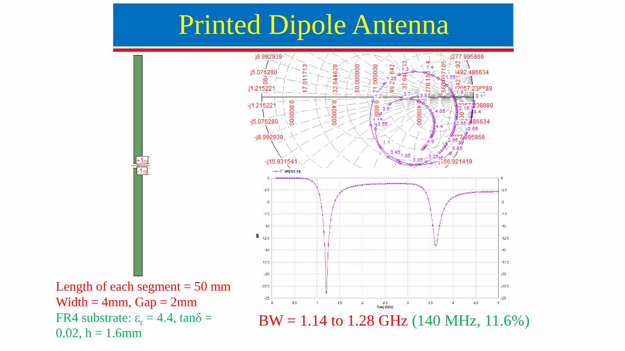
Printed Dipole Antenna
BW = 1.14 to 1.28 GHz (140 MHz, 11.6%)
Length of each segment = 50 mm
Width = 4mm, Gap = 2mm
FR4 substrate: εr = 4.4, tanδ =
0.02, h = 1.6mm
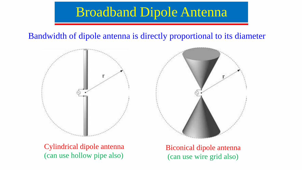
Broadband Dipole Antenna
Bandwidth of dipole antenna is directly proportional to its diameter
Cylindrical dipole antenna
(can use hollow pipe also) Biconical dipole antenna
(can use wire grid also)
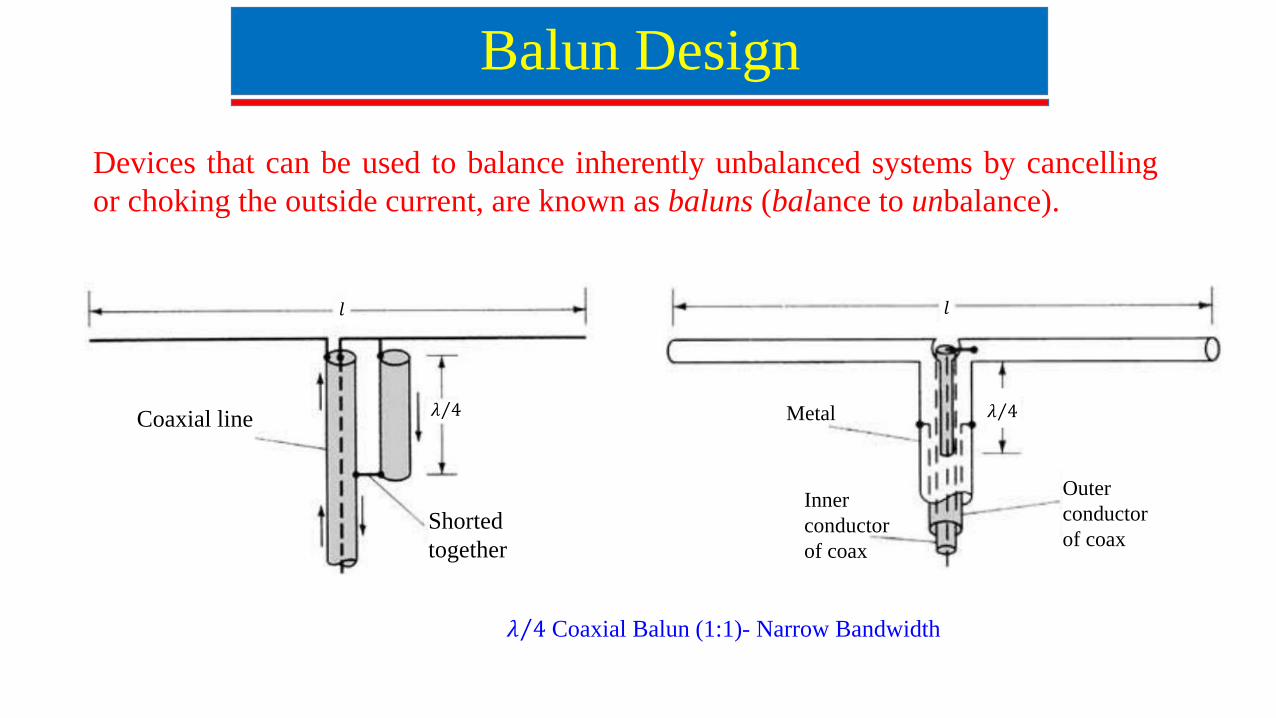
Balun Design
Devices that can be used to balance inherently unbalanced systems by cancelling
or choking the outside current, are known as baluns (balance to unbalance).
Coaxial line
Shorted
together
𝜆 4
𝑙 𝑙
𝜆 4
Outer
conductor
of coax
Inner
conductor
of coax
Metal
𝜆 4 Coaxial Balun (1:1)- Narrow Bandwidth
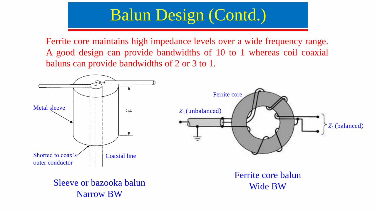
Sleeve or bazooka balun
Narrow BW
)𝑍1(balanced
)𝑍1(unbalanced
Ferrite core
Metal sleeve
Shorted to coax’s
outer conductorCoaxial line
Ferrite core balun
Wide BW
Balun Design (Contd.)
Ferrite core maintains high impedance levels over a wide frequency range.
A good design can provide bandwidths of 10 to 1 whereas coil coaxial
baluns can provide bandwidths of 2 or 3 to 1.
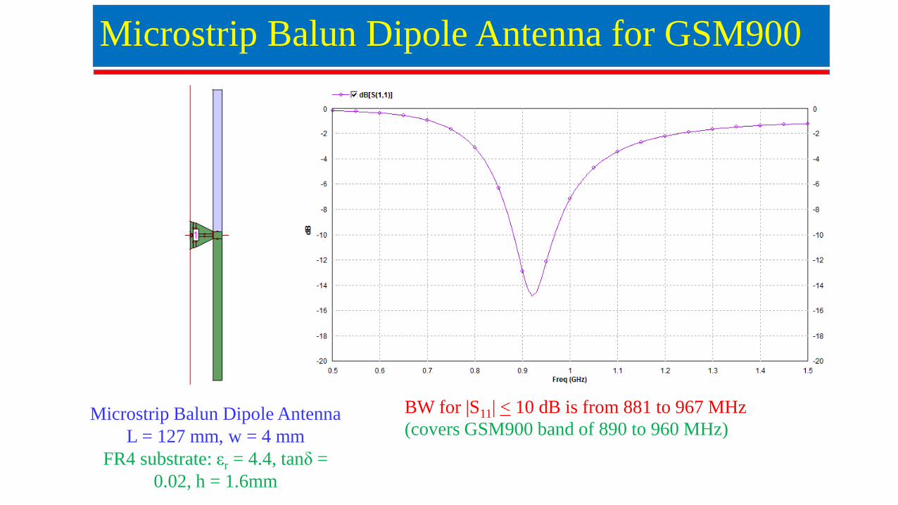
Microstrip Balun Dipole Antenna for GSM900
Microstrip Balun Dipole Antenna
L = 127 mm, w = 4 mm
FR4 substrate: εr = 4.4, tanδ =
0.02, h = 1.6mm
BW for |S11| < 10 dB is from 881 to 967 MHz
(covers GSM900 band of 890 to 960 MHz)
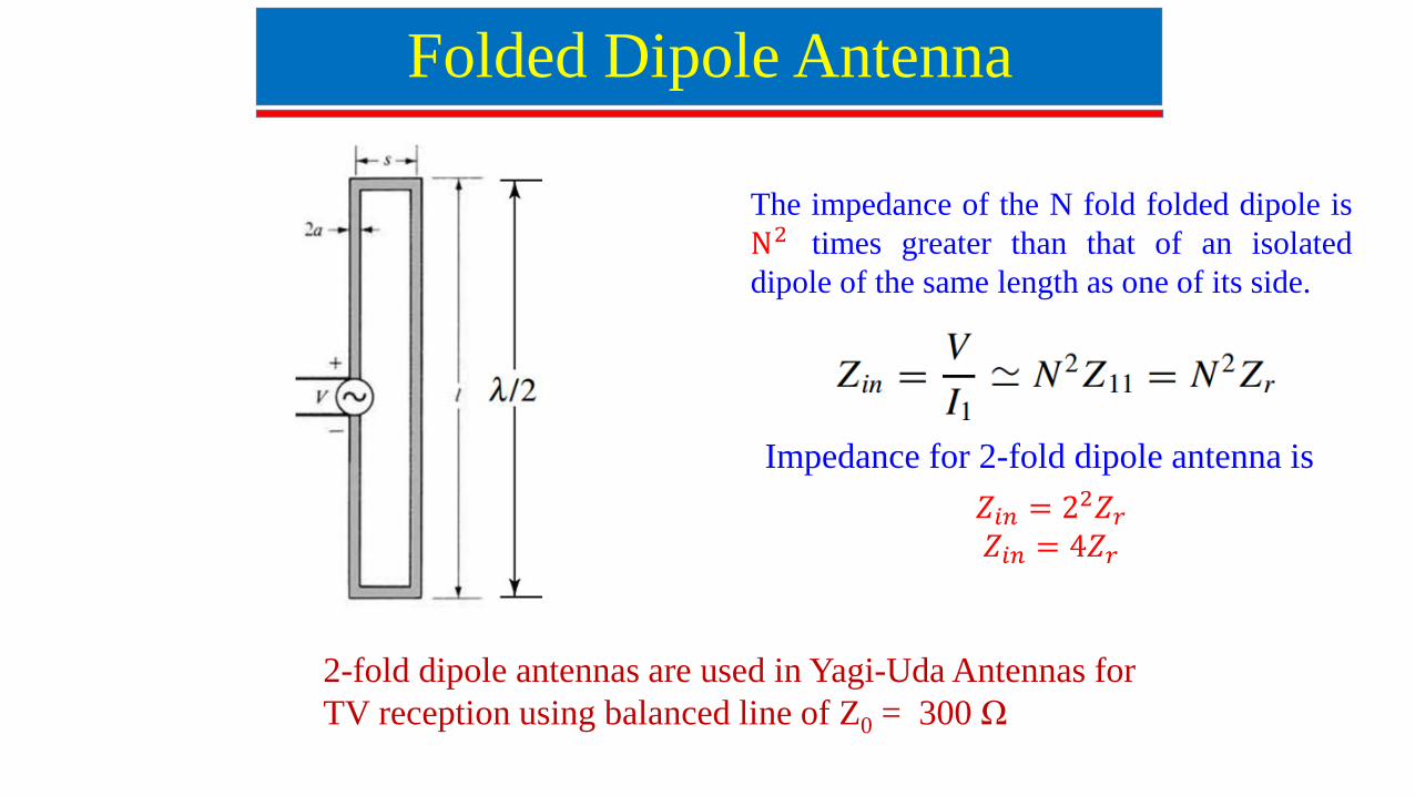
Folded Dipole Antenna
The impedance of the N fold folded dipole is
N2 times greater than that of an isolated
dipole of the same length as one of its side.
Impedance for 2-fold dipole antenna is
𝑍𝑖𝑛 = 22𝑍𝑟
𝑍𝑖𝑛 = 4𝑍𝑟
2-fold dipole antennas are used in Yagi-Uda Antennas for
TV reception using balanced line of Z0 = 300 Ω
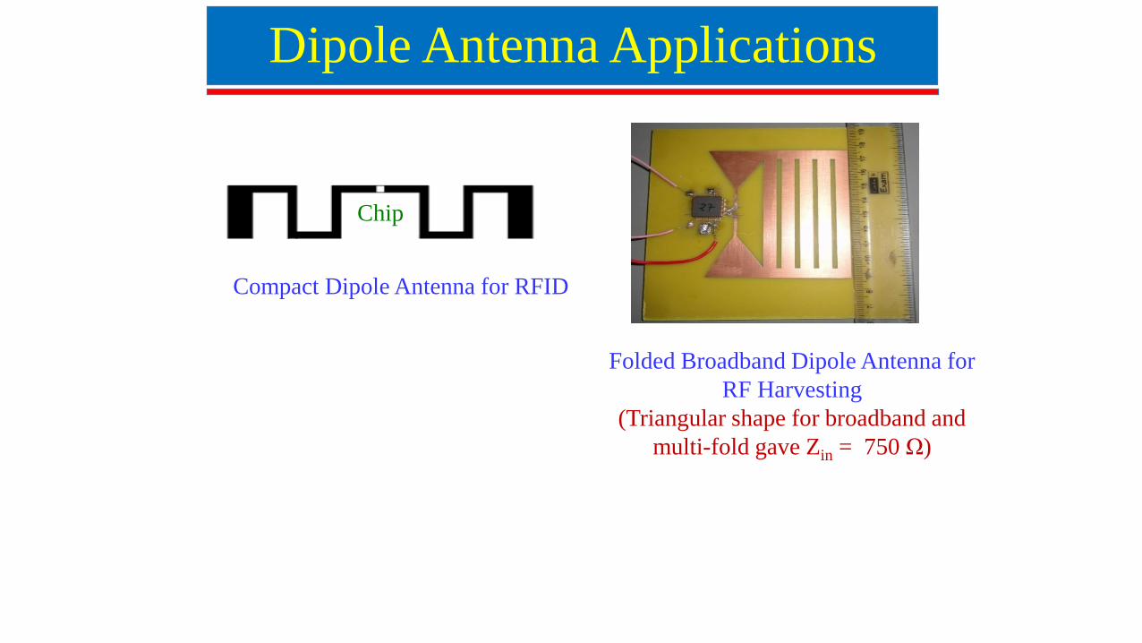
Dipole Antenna Applications
Compact Dipole Antenna for RFID
Chip
Folded Broadband Dipole Antenna for
RF Harvesting
(Triangular shape for broadband and
multi-fold gave Zin = 750 Ω)