JCPS-8-850+ Power Splitter/Combiner JCPS-8-850 · PDF fileJCPS-8-850+ JCPS-8-850 electrical...
1
Freq. (MHz) Total Loss 1 (dB) Amplitude Unbalance (dB) Isolation (dB) VSWR S VSWR 1 VSWR 8 S-1 S-2 S-3 S-4 S-6 S-8 1-2 1-7 3-4 5-7 10.00 9.97 9.88 9.85 9.85 9.83 9.84 0.14 37.47 45.11 36.73 33.59 1.12 1.20 1.24 30.00 9.94 9.85 9.82 9.83 9.81 9.83 0.13 35.88 47.49 35.30 33.43 1.07 1.14 1.18 50.00 9.99 9.90 9.85 9.87 9.87 9.88 0.14 33.43 47.78 33.03 32.56 1.07 1.14 1.18 80.00 10.06 9.96 9.92 9.93 9.94 9.94 0.14 30.18 45.86 29.90 30.72 1.08 1.14 1.17 150.00 10.20 10.08 10.05 10.05 10.08 10.08 0.15 25.88 42.07 25.65 27.12 1.14 1.12 1.15 300.00 10.51 10.35 10.32 10.32 10.39 10.36 0.19 20.60 35.90 20.40 21.65 1.24 1.05 1.08 410.00 10.71 10.51 10.48 10.47 10.61 10.54 0.24 19.46 33.82 19.25 19.70 1.29 1.01 1.02 430.00 10.73 10.54 10.50 10.48 10.64 10.57 0.25 19.55 33.59 19.32 19.00 1.29 1.02 1.02 500.00 10.81 10.59 10.56 10.55 10.75 10.63 0.26 20.04 33.93 19.84 18.67 1.29 1.05 1.05 575.00 10.87 10.66 10.61 10.63 10.88 10.70 0.30 21.63 35.15 21.98 18.29 1.26 1.09 1.10 675.00 10.92 10.76 10.66 10.70 11.05 10.77 0.43 23.04 36.83 26.33 18.19 1.19 1.13 1.16 775.00 11.03 10.95 10.77 10.86 11.32 10.89 0.62 21.47 38.45 25.87 18.10 1.13 1.16 1.21 820.00 11.10 11.05 10.81 10.91 11.44 10.93 0.71 19.95 39.36 22.83 18.03 1.11 1.18 1.24 840.00 11.20 11.16 10.90 11.02 11.59 11.02 0.78 19.15 39.94 21.31 18.03 1.12 1.19 1.25 850.00 11.25 11.23 10.94 11.08 11.67 11.05 0.82 18.91 40.13 20.89 18.03 1.12 1.19 1.26 Notes A. Performance and quality attributes and conditions not expressly stated in this specification document are intended to be excluded and do not form a part of this specification document. B. Electrical specifications and performance data contained in this specification document are based on Mini-Circuit’s applicable established test performance criteria and measurement instructions. C. The parts covered by this specification document are subject to Mini-Circuits standard limited warranty and terms and conditions (collectively, “Standard Terms”); Purchasers of this part are entitled to the rights and benefits contained therein. For a full statement of the Standard Terms and the exclusive rights and remedies thereunder, please visit Mini-Circuits’ website at www.minicircuits.com/MCLStore/terms.jsp Mini-Circuits ® www.minicircuits.com P.O. Box 350166, Brooklyn, NY 11235-0003 (718) 934-4500 [email protected] FREQ. RANGE (MHz) ISOLATION (dB) INSERTION LOSS (dB) ABOVE 9.0 dB PHASE UNBALANCE (Degrees) AMPLITUDE UNBALANCE (dB) f L -f U L M U L M U L M U L M U Typ. Min Typ. Min Typ. Min Typ. Max. Typ. Max. Typ. Max. Max. Max. Max. Max. Max. Max. 10-850 34 20 25 17 20 15 0.8 1.5 1.0 2.5 1.8 3.0 5 10 20 0.6 0.7 1.0 L = low range [f L to 10 f L ] M = mid range [10 f L to f U /2] U = upper range [f U /2 to f U ] A B C D E F G .870 .800 -- .100 .250 .100 .100 22.10 20.32 -- 2.54 6.35 2.54 2.54 H J K L wt .047 .065 .065 .890 grams 1.19 1.65 1.65 22.61 4.0 PCB Land Pattern Suggested Layout, Tolerance to be within ±.002 Typical Performance Data Electrical Specifications Maximum Ratings Pin Connections SUM PORT 1 PORT 1 3 PORT 2 4 PORT 3 5 PORT 4 6 PORT 5 9 PORT 6 10 PORT 7 11 PORT 8 12 GROUND 2,7,8,13,14 Operating Temperature -40°C to 85°C Storage Temperature -55°C to 100°C Power Input (as a splitter) 1W max. Internal Dissipation 0.875W max. Outline Drawing Outline Dimensions ( ) inch mm JCPS-8-850+ JCPS-8-850 electrical schematic 8 Way-0° 50Ω 10 to 850 MHz Power Splitter/Combiner REV. D M151107 JCPS-8-850 WZ/TD/CP/AM 150818 Surface Mount Features • wideband, 10 to 850 MHz • aqueous washable • shielded metal case • J-leads for good solderability & strain relief Applications • VHF/UHF • cellular • instrumentation • communication systems JCPS-8-850 TOTAL LOSS 9.0 9.8 10.6 11.4 12.2 13.0 0 170 340 510 680 850 FREQUENCY (MHz) TOTAL LOSS (dB) S-1(dB) S-8(dB) JCPS-8-850 ISOLATION 10 22 34 46 58 70 0 170 340 510 680 850 FREQUENCY (MHz) ISOLATION (dB) 1-2(dB) 1-7(dB) 5-7(dB) JCPS-8-850 VSWR 1.0 1.1 1.2 1.3 1.4 1.5 0 170 340 510 680 850 FREQUENCY (MHz) VSWR #S-VSWR #1-VSWR Demo Board MCL P/N: TB-134 Suggested PCB Layout (PL-037) 1. Total Loss = Insertion Loss + 9dB splitter loss. +RoHS Compliant The +Suffix identifies RoHS Compliance. See our web site for RoHS Compliance methodologies and qualifications CASE STYLE: BG291
Transcript of JCPS-8-850+ Power Splitter/Combiner JCPS-8-850 · PDF fileJCPS-8-850+ JCPS-8-850 electrical...
Freq.(MHz)
Total Loss1
(dB)AmplitudeUnbalance
(dB)
Isolation(dB)
VSWRS
VSWR1
VSWR8
S-1 S-2 S-3 S-4 S-6 S-8 1-2 1-7 3-4 5-7 10.00 9.97 9.88 9.85 9.85 9.83 9.84 0.14 37.47 45.11 36.73 33.59 1.12 1.20 1.24 30.00 9.94 9.85 9.82 9.83 9.81 9.83 0.13 35.88 47.49 35.30 33.43 1.07 1.14 1.18 50.00 9.99 9.90 9.85 9.87 9.87 9.88 0.14 33.43 47.78 33.03 32.56 1.07 1.14 1.18 80.00 10.06 9.96 9.92 9.93 9.94 9.94 0.14 30.18 45.86 29.90 30.72 1.08 1.14 1.17 150.00 10.20 10.08 10.05 10.05 10.08 10.08 0.15 25.88 42.07 25.65 27.12 1.14 1.12 1.15 300.00 10.51 10.35 10.32 10.32 10.39 10.36 0.19 20.60 35.90 20.40 21.65 1.24 1.05 1.08 410.00 10.71 10.51 10.48 10.47 10.61 10.54 0.24 19.46 33.82 19.25 19.70 1.29 1.01 1.02 430.00 10.73 10.54 10.50 10.48 10.64 10.57 0.25 19.55 33.59 19.32 19.00 1.29 1.02 1.02 500.00 10.81 10.59 10.56 10.55 10.75 10.63 0.26 20.04 33.93 19.84 18.67 1.29 1.05 1.05 575.00 10.87 10.66 10.61 10.63 10.88 10.70 0.30 21.63 35.15 21.98 18.29 1.26 1.09 1.10 675.00 10.92 10.76 10.66 10.70 11.05 10.77 0.43 23.04 36.83 26.33 18.19 1.19 1.13 1.16 775.00 11.03 10.95 10.77 10.86 11.32 10.89 0.62 21.47 38.45 25.87 18.10 1.13 1.16 1.21 820.00 11.10 11.05 10.81 10.91 11.44 10.93 0.71 19.95 39.36 22.83 18.03 1.11 1.18 1.24 840.00 11.20 11.16 10.90 11.02 11.59 11.02 0.78 19.15 39.94 21.31 18.03 1.12 1.19 1.25 850.00 11.25 11.23 10.94 11.08 11.67 11.05 0.82 18.91 40.13 20.89 18.03 1.12 1.19 1.26
NotesA. Performance and quality attributes and conditions not expressly stated in this specification document are intended to be excluded and do not form a part of this specification document. B. Electrical specifications and performance data contained in this specification document are based on Mini-Circuit’s applicable established test performance criteria and measurement instructions. C. The parts covered by this specification document are subject to Mini-Circuits standard limited warranty and terms and conditions (collectively, “Standard Terms”); Purchasers of this part are entitled to the rights and benefits contained therein. For a full statement of the Standard Terms and the exclusive rights and remedies thereunder, please visit Mini-Circuits’ website at www.minicircuits.com/MCLStore/terms.jsp
Mini-Circuits®
www.minicircuits.com P.O. Box 350166, Brooklyn, NY 11235-0003 (718) 934-4500 [email protected]
FREQ. RANGE(MHz)
ISOLATION(dB)
INSERTION LOSS (dB)ABOVE 9.0 dB
PHASE UNBALANCE
(Degrees)
AMPLITUDEUNBALANCE
(dB)
fL-fU
L M U L M U L M U L M UTyp. Min Typ. Min Typ. Min Typ. Max. Typ. Max. Typ. Max. Max. Max. Max. Max. Max. Max.
10-850 34 20 25 17 20 15 0.8 1.5 1.0 2.5 1.8 3.0 5 10 20 0.6 0.7 1.0
L = low range [fL to 10 fL] M = mid range [10 fL to fU/2] U = upper range [fU/2 to fU]
A B C D E F G.870 .800 -- .100 .250 .100 .100
22.10 20.32 -- 2.54 6.35 2.54 2.54
H J K L wt.047 .065 .065 .890 grams1.19 1.65 1.65 22.61 4.0
PCB Land Pattern
Suggested Layout, Tolerance to be within ±.002
Typical Performance Data
Electrical Specifications
Maximum Ratings
Pin ConnectionsSUM PORT 1
PORT 1 3
PORT 2 4
PORT 3 5
PORT 4 6
PORT 5 9
PORT 6 10
PORT 7 11
PORT 8 12
GROUND 2,7,8,13,14
Operating Temperature -40°C to 85°C
Storage Temperature -55°C to 100°C
Power Input (as a splitter) 1W max.
Internal Dissipation 0.875W max.
Outline Drawing
Outline Dimensions ( )inchmm
JCPS-8-850+JCPS-8-850
electrical schematic
8 Way-0° 50Ω 10 to 850 MHz
Power Splitter/Combiner
REV. DM151107JCPS-8-850WZ/TD/CP/AM150818
Surface Mount
Features• wideband, 10 to 850 MHz• aqueous washable• shielded metal case• J-leads for good solderability & strain relief
Applications• VHF/UHF• cellular• instrumentation• communication systems
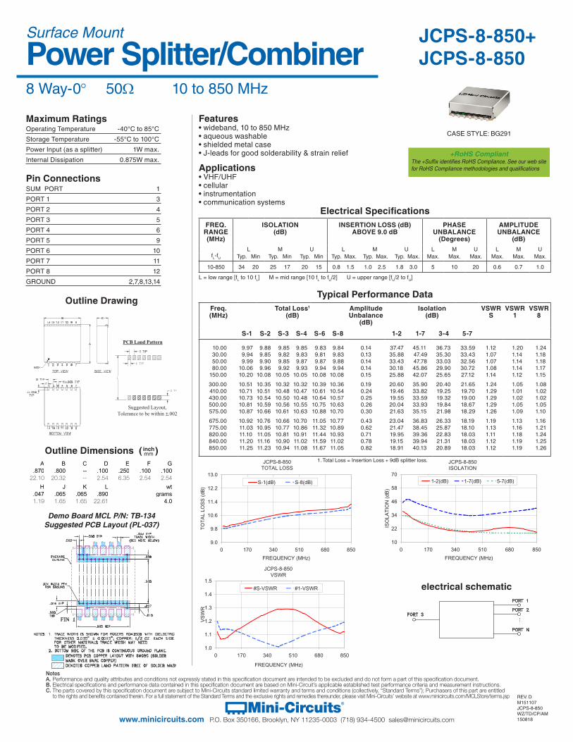
JCPS-8-850TOTAL LOSS
9.0
9.8
10.6
11.4
12.2
13.0
0 170 340 510 680 850
FREQUENCY (MHz)
TO
TA
L LO
SS
(dB
)
S-1(dB) S-8(dB)
JCPS-8-850ISOLATION
10
22
34
46
58
70
0 170 340 510 680 850
FREQUENCY (MHz)
ISO
LAT
ION
(dB
)
1-2(dB) 1-7(dB) 5-7(dB)
JCPS-8-850VSWR
1.0
1.1
1.2
1.3
1.4
1.5
0 170 340 510 680 850
FREQUENCY (MHz)
VS
WR
#S-VSWR #1-VSWR
Demo Board MCL P/N: TB-134Suggested PCB Layout (PL-037)
1. Total Loss = Insertion Loss + 9dB splitter loss.
+RoHS CompliantThe +Suffix identifies RoHS Compliance. See our web site for RoHS Compliance methodologies and qualifications
CASE STYLE: BG291