ITU Training on Conformance and Interoperability for AFR ... · EMC fundamentals ITU Training on...
57
EMC fundamentals ITU Training on Conformance and Interoperability for AFR Regions CERT, 28 October – 1 st November 2013, Tunis 1 [email protected] [email protected]
Transcript of ITU Training on Conformance and Interoperability for AFR ... · EMC fundamentals ITU Training on...

EMC fundamentals
ITU Training on Conformance and Interoperability
for AFR Regions
CERT, 28 October – 1st November 2013, Tunis
1
Basics of electromagnetics
2
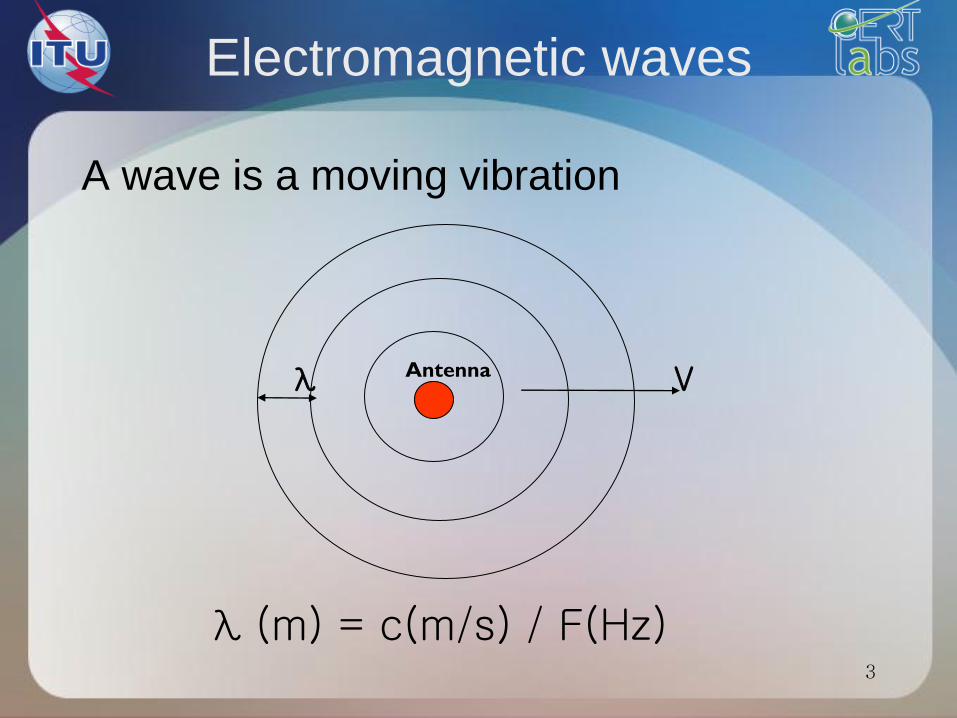
A wave is a moving vibration
Electromagnetic waves
λ (m) = c(m/s) / F(Hz)
Antenna V λ
3
Definitions
• The wavelength is the distance traveled
by a wave in an oscillation cycle
• Frequency is measured by the number
of cycles per second and the unit is Hz
. One cycle per second is one Hertz.
4
Electromagnetic waves (2)
• An electromagnetic wave consists of:
an electric field E (produced by the force of
electric charges)
a magnetic field H (produced by the movement
of electric charges)
• The fields E and H are orthogonal and are
moving at the speed of light c = 3. 108 m/s
5
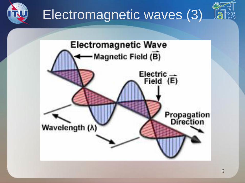
Electromagnetic waves (3)
6
E and H fields
E(V/m)
l
H(A
/m)
d
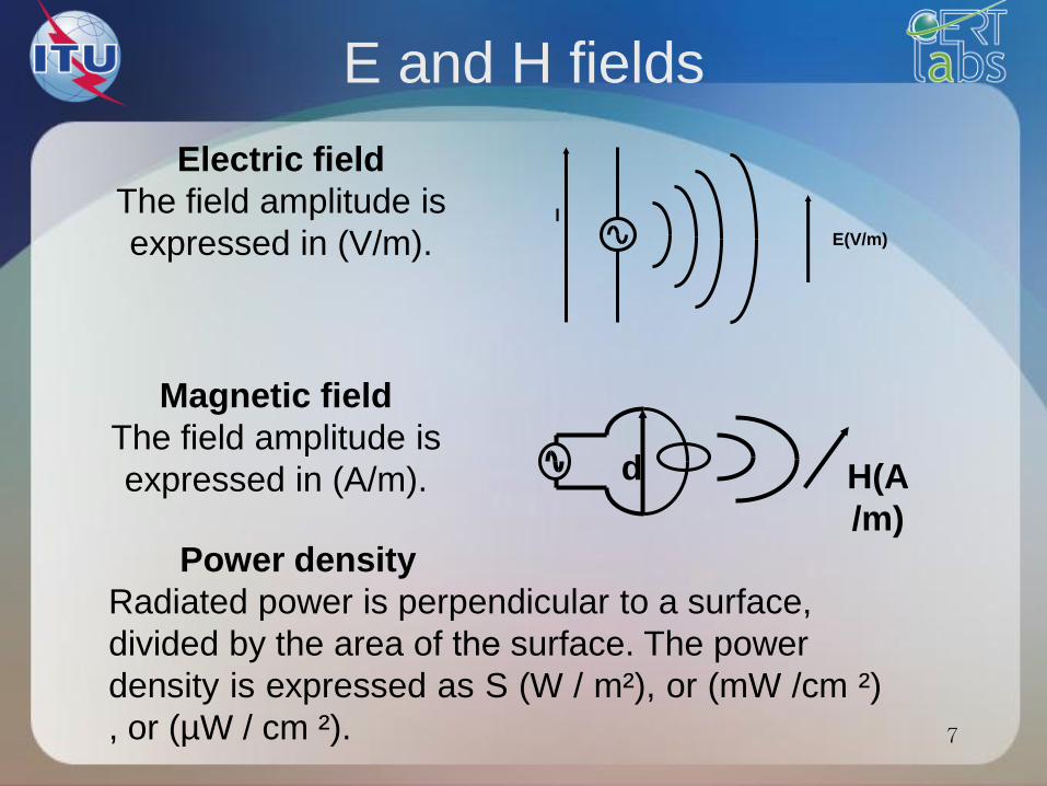
Electric field
The field amplitude is
expressed in (V/m).
Magnetic field
The field amplitude is
expressed in (A/m).
Power density
Radiated power is perpendicular to a surface,
divided by the area of the surface. The power
density is expressed as S (W / m²), or (mW /cm ²)
, or (µW / cm ²). 7
E and H fields
• Near a whip, the dominant field is the E
field. The impedance in this area is Zc
> 377 ohms.
• Near a loop, the dominant field is the H
field. The impedance in this area is Z
c <377 ohms.
8
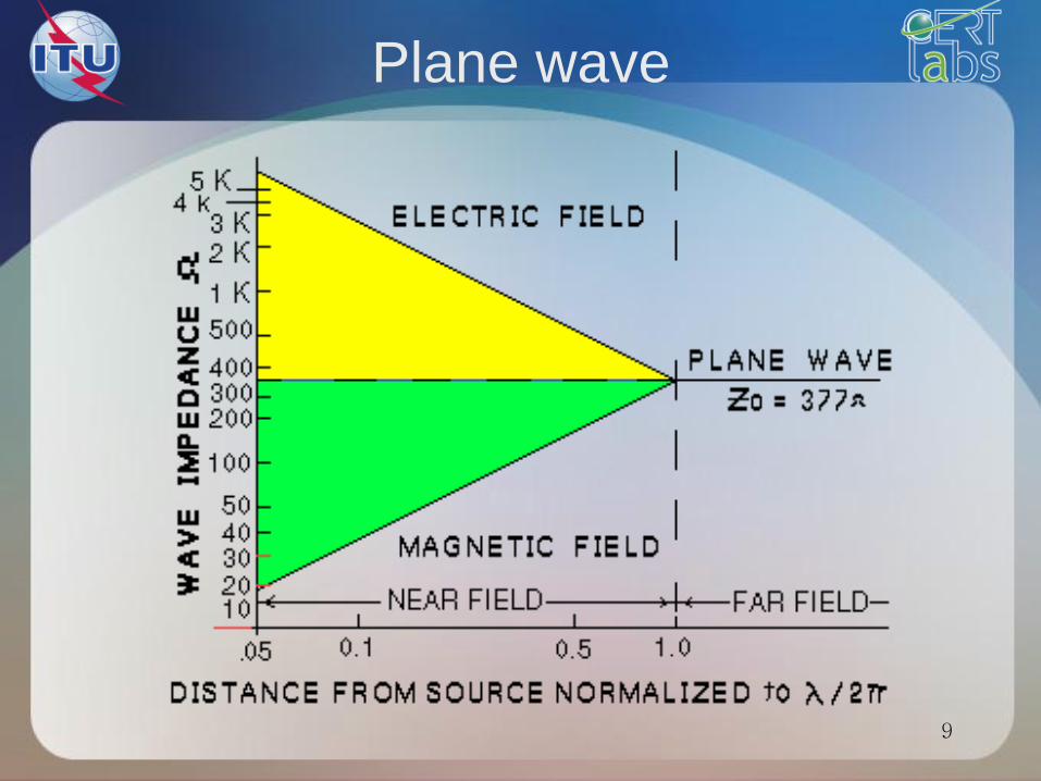
Plane wave
9
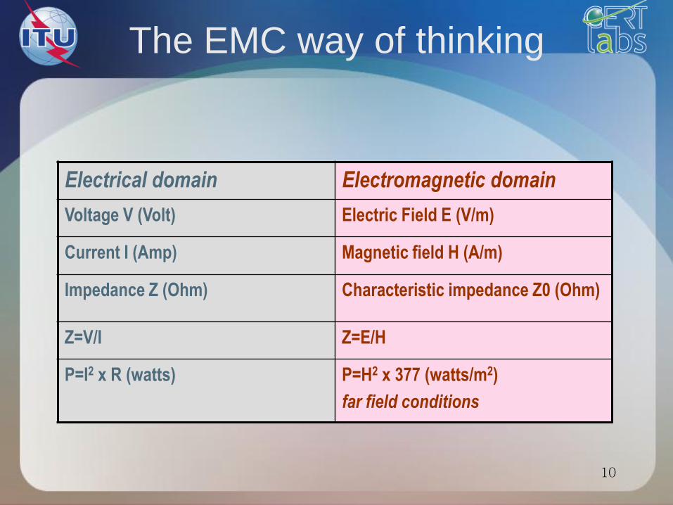
The EMC way of thinking
Electrical domain Electromagnetic domain
Voltage V (Volt) Electric Field E (V/m)
Current I (Amp) Magnetic field H (A/m)
Impedance Z (Ohm) Characteristic impedance Z0 (Ohm)
Z=V/I Z=E/H
P=I2 x R (watts) P=H2 x 377 (watts/m2)
far field conditions
10
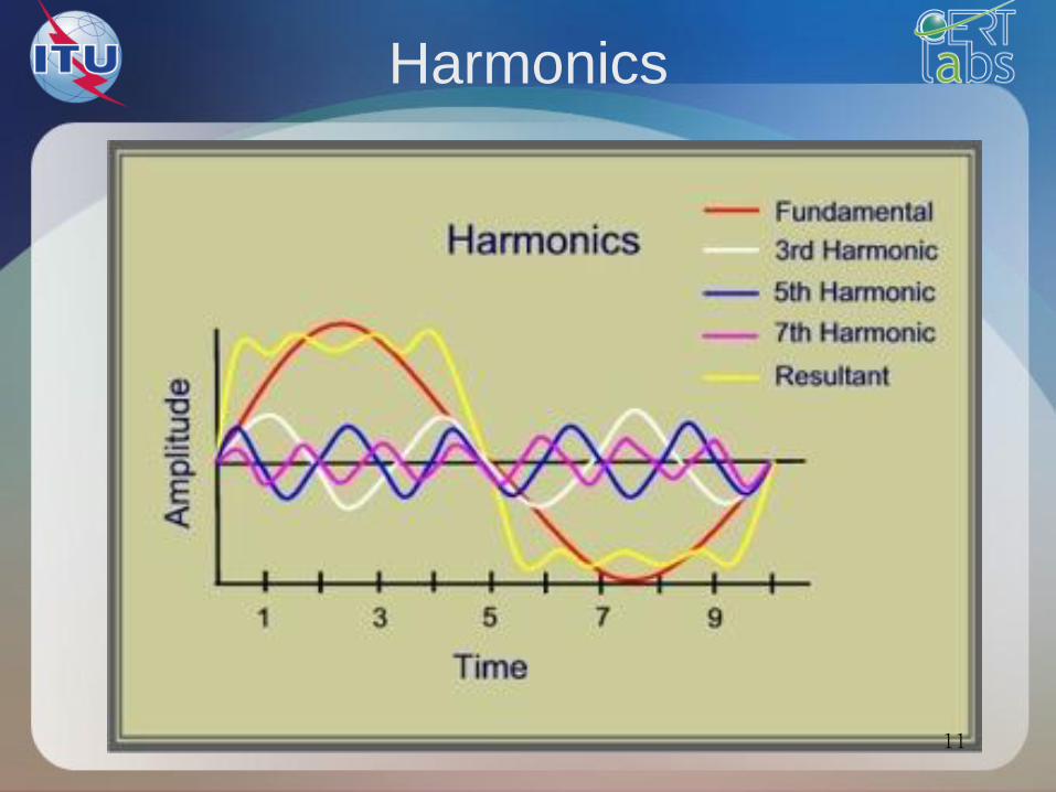
Harmonics
11
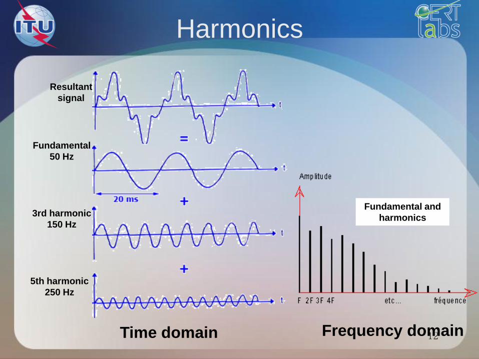
Harmonics
Time domain Frequency domain
Resultant
signal
Fundamental
50 Hz
3rd harmonic
150 Hz
5th harmonic
250 Hz
Fundamental and
harmonics
12
EMC results
Why in frequency domain (Hz) ?
Why in logarithm scale (dB) ?
• Time domain aspect is dominated by the major frequency
harmonics
• Distinguish contributions of each harmonics, even small ones
• Signals are composed of high and low amplitude harmonics
• Very large dynamic (from µV to several mV)
• Logarithm scale is requested
13
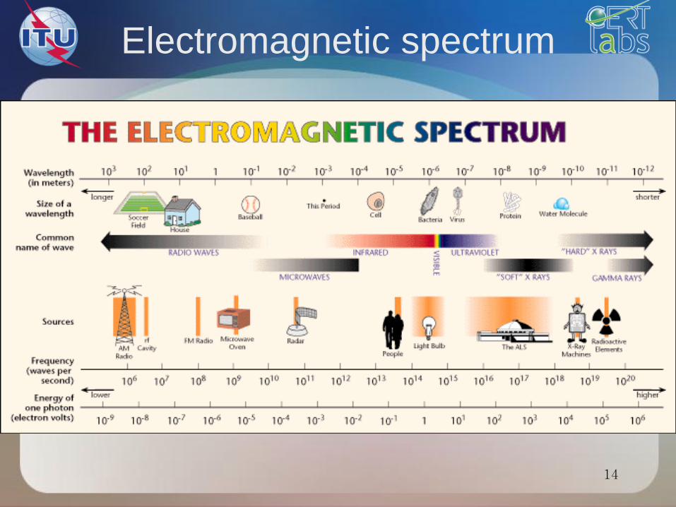
Electromagnetic spectrum
14
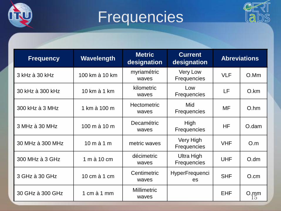
Frequencies
Frequency Wavelength Metric
designation
Current
designation Abreviations
3 kHz à 30 kHz 100 km à 10 km myriamétric
waves
Very Low
Frequencies VLF O.Mm
30 kHz à 300 kHz 10 km à 1 km kilometric
waves
Low
Frequencies LF O.km
300 kHz à 3 MHz 1 km à 100 m Hectometric
waves
Mid
Frequencies MF O.hm
3 MHz à 30 MHz 100 m à 10 m Decamétric
waves
High
Frequencies HF O.dam
30 MHz à 300 MHz 10 m à 1 m metric waves Very High
Frequencies VHF O.m
300 MHz à 3 GHz 1 m à 10 cm décimetric
waves
Ultra High
Frequencies UHF O.dm
3 GHz à 30 GHz 10 cm à 1 cm Centimetric
waves
HyperFrequenci
es SHF O.cm
30 GHz à 300 GHz 1 cm à 1 mm Millimetric
waves EHF O.mm
15
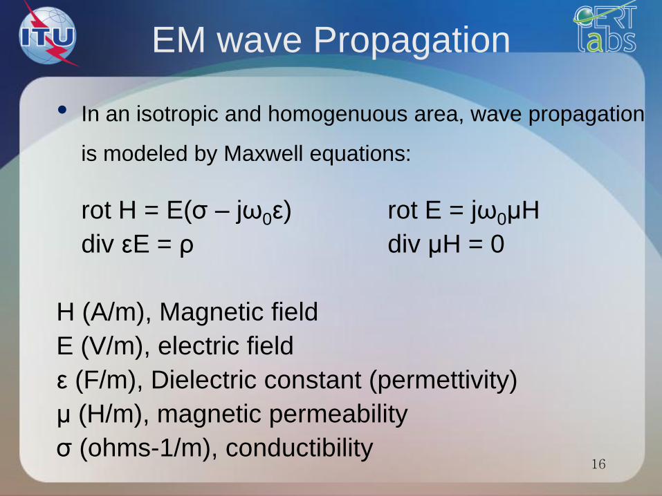
EM wave Propagation
• In an isotropic and homogenuous area, wave propagation
is modeled by Maxwell equations:
rot H = E(σ – jω0ε) rot E = jω0μH
div εE = ρ div μH = 0
H (A/m), Magnetic field
E (V/m), electric field
ε (F/m), Dielectric constant (permettivity)
μ (H/m), magnetic permeability
σ (ohms-1/m), conductibility
16
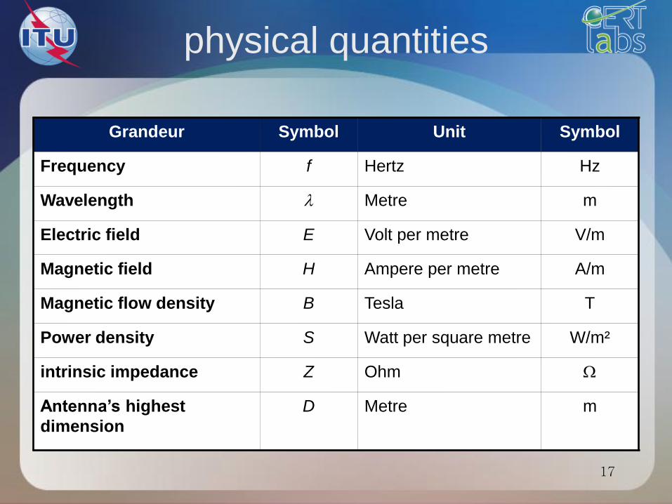
physical quantities
Grandeur Symbol Unit Symbol
Frequency f Hertz Hz
Wavelength Metre m
Electric field E Volt per metre V/m
Magnetic field H Ampere per metre A/m
Magnetic flow density B Tesla T
Power density S Watt per square metre W/m²
intrinsic impedance Z Ohm
Antenna’s highest
dimension
D Metre m
17
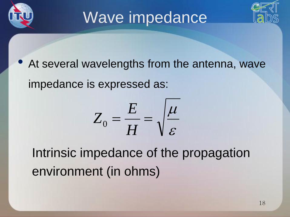
Wave impedance
• At several wavelengths from the antenna, wave
impedance is expressed as:
Intrinsic impedance of the propagation
environment (in ohms)
H
EZ0
18
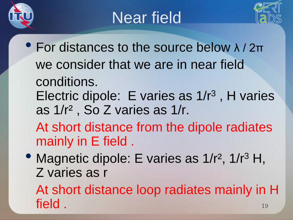
Near field
• For distances to the source below λ / 2π
we consider that we are in near field
conditions. Electric dipole: E varies as 1/r3 , H varies as 1/r² , So Z varies as 1/r.
At short distance from the dipole radiates mainly in E field .
• Magnetic dipole: E varies as 1/r², 1/r3 H, Z varies as r
At short distance loop radiates mainly in H field .
19
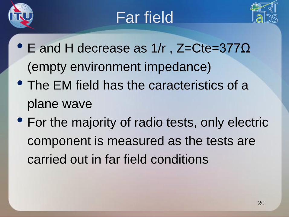
Far field
• E and H decrease as 1/r , Z=Cte=377Ω
(empty environment impedance)
• The EM field has the caracteristics of a
plane wave
• For the majority of radio tests, only electric
component is measured as the tests are
carried out in far field conditions
20
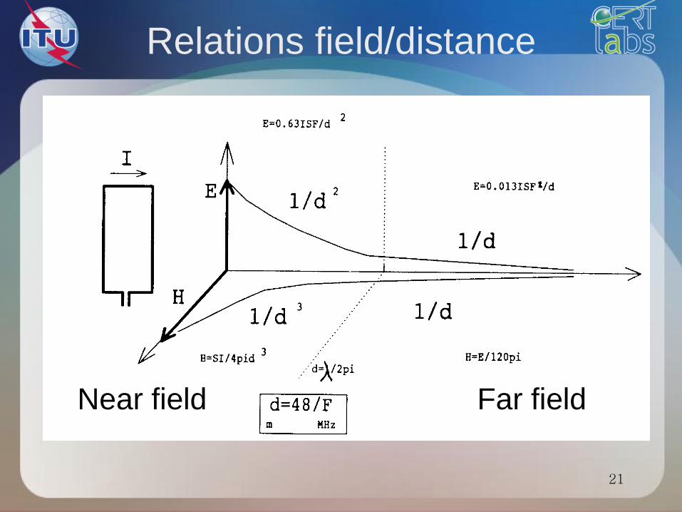
Relations field/distance
Near field Far field
21
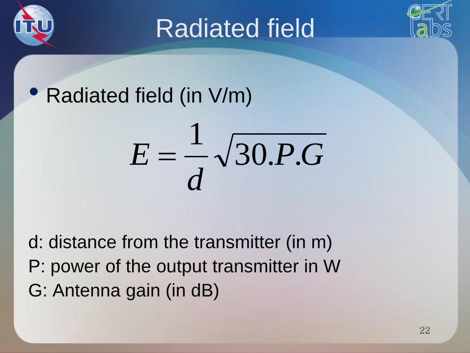
Radiated field
• Radiated field (in V/m)
d: distance from the transmitter (in m)
P: power of the output transmitter in W
G: Antenna gain (in dB)
GPd
E ..301
22
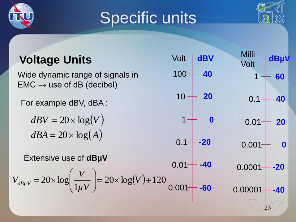
Specific units
Voltage Units
Wide dynamic range of signals in
EMC → use of dB (decibel)
0.1
10
1
100
0.01
Volt dBV
0.001
0.001
0.1
0.01
1
0.0001
Milli
Volt dBµV
0.00001
For example dBV, dBA :
AdBA
VdBV
log20
log20
Extensive use of dBµV
120log201
log20
V
µV
VVdBµV
0
20
40
-20
-40
-60
0
20
40
-20
-40
60
23
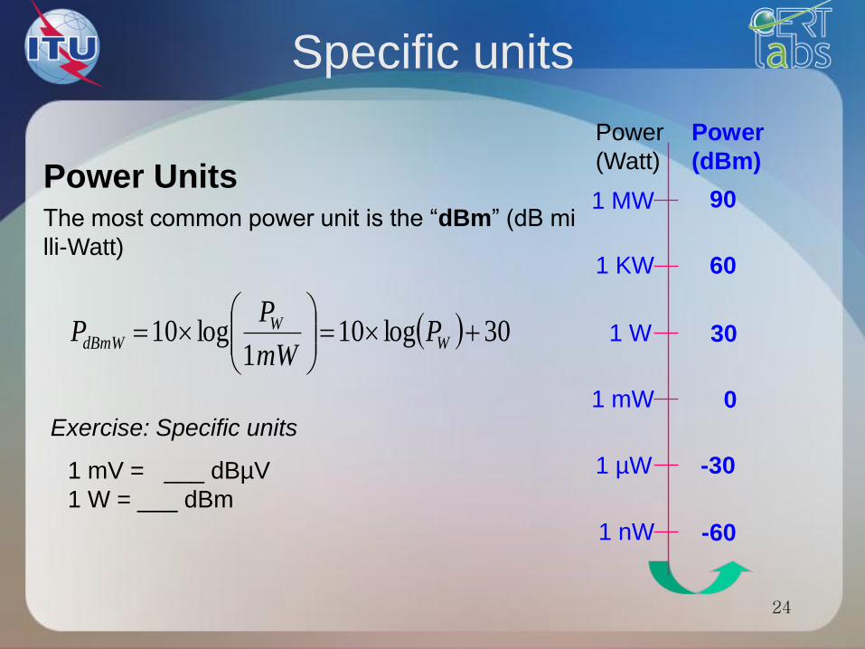
Specific units
The most common power unit is the “dBm” (dB mi
lli-Watt)
Power Units
1 mV = ___ dBµV
1 W = ___ dBm
Exercise: Specific units
30log101
log10
W
WdBmW P
mW
PP 1 W
1 MW
1 KW
Power
(Watt)
1 mW
Power
(dBm)
1 µW
1 nW
30
90
60
0
-30
-60
24
25
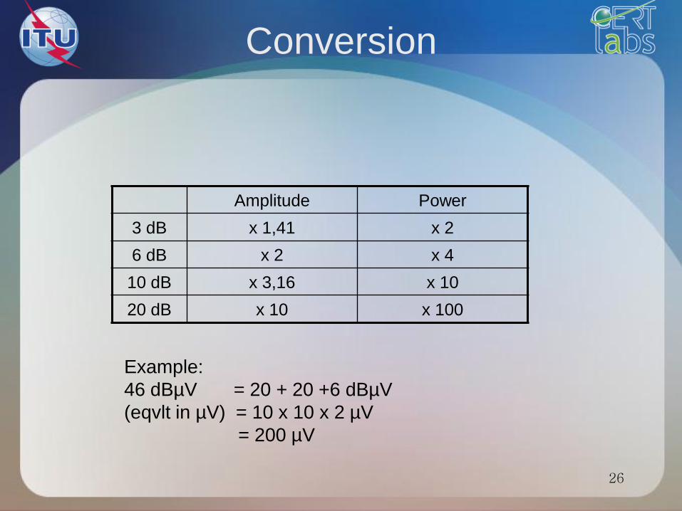
Conversion
Example:
46 dBµV = 20 + 20 +6 dBµV
(eqvlt in µV) = 10 x 10 x 2 µV
= 200 µV
26
Amplitude Power
3 dB x 1,41 x 2
6 dB x 2 x 4
10 dB x 3,16 x 10
20 dB x 10 x 100
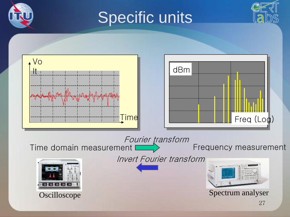
Specific units
Time domain measurement
Volt
Time
Frequency measurement Fourier transform
Freq (Log)
dBm
Invert Fourier transform
Spectrum analyser Oscilloscope 27
Electromagnetic compatibility
28
Electromagnetic interference
• Electric and electronic systems are not isolated
from their environment.
• Electromagnetic energy can unintentionally
cross their borders:
to enter,
or to escape.
• This energy is called stray electromagnetic
interference.
29
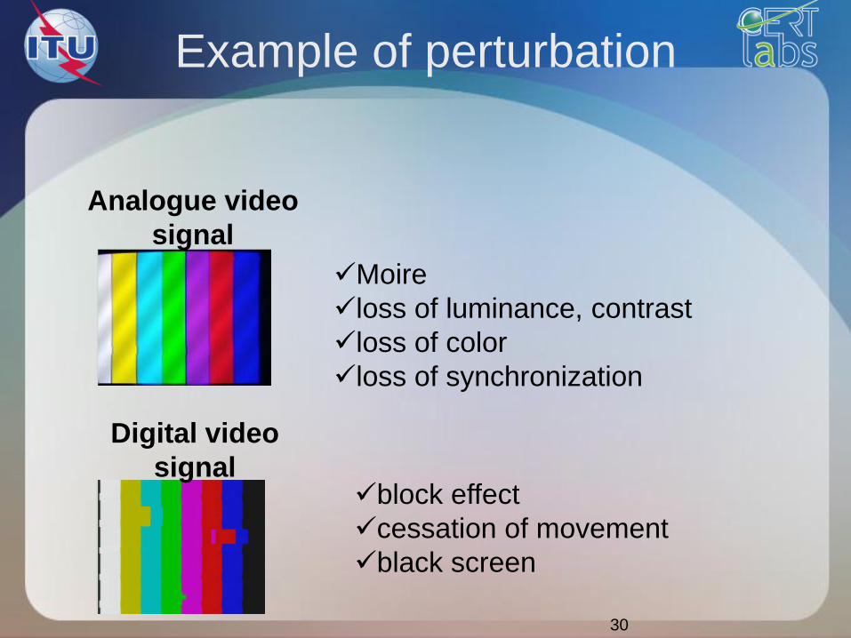
Example of perturbation
30
Analogue video
signal
Digital video
signal
Moire
loss of luminance, contrast
loss of color
loss of synchronization
block effect
cessation of movement
black screen
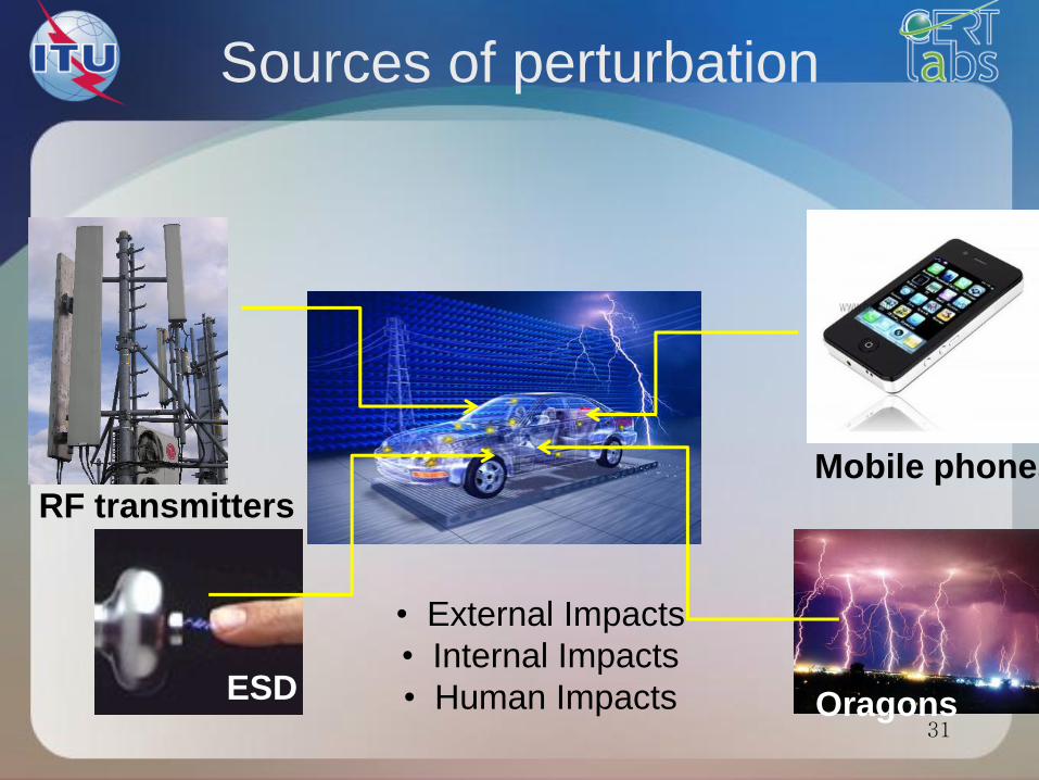
Sources of perturbation
• External Impacts
• Internal Impacts
• Human Impacts
RF transmitters Mobile phones
Oragons ESD
31
EMC (1)
Electric equipment:
1. Victim of its environment:
Malfunction
Temporary malfunction or permanent
2. Source of disturbance in its environment
32
EMC (2)
According to the european directive
2004/108/CEE, EMC refers to:
• the ability of an equipment or a system to
perform satisfactorily in its electromagnetic
environment
• without introducing intolerable interference
into any thing in that environment.
33
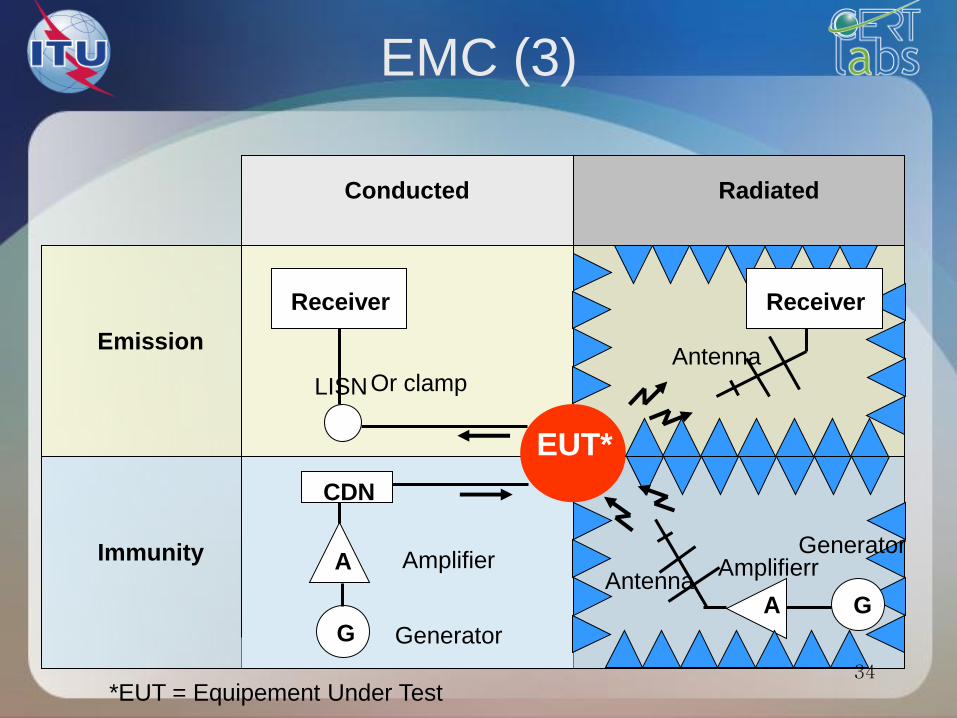
EMC (3)
EUT*
*EUT = Equipement Under Test
Conducted Radiated
Emission
Immunity
Receiver
Antenna
A Antenna
Amplifierr
Or clamp LISN
Generator G
A
CDN
Amplifier
Receiver
G
Generator
34
Conducted/Radiated
• The parasites circulating currents and
voltages in cables or equipments will
radiate.
• The radiated power will also induce
currents and stray voltages in the different
interconnections.
=> The conducted and radiated disturbances
are closely coupled.
35
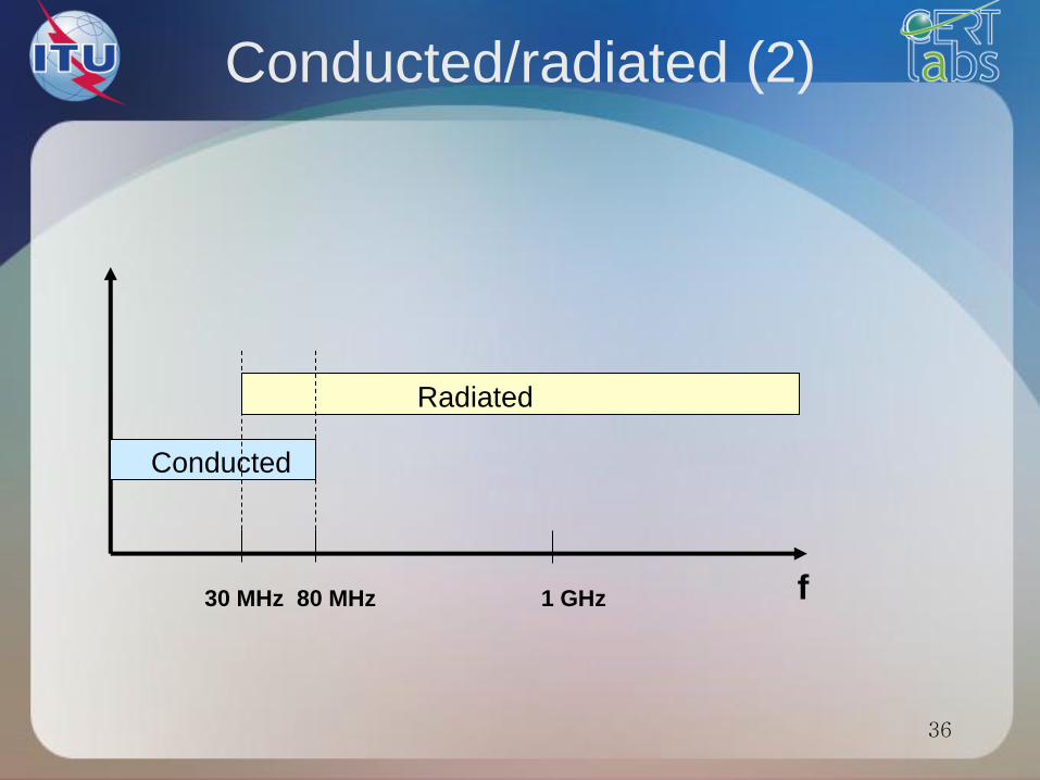
Conducted/radiated (2)
30 MHz 80 MHz 1 GHz
Conducted
Radiated
f
36
Test sites
37
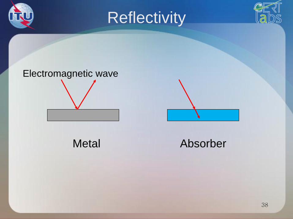
Reflectivity
Metal Absorber
Electromagnetic wave
38
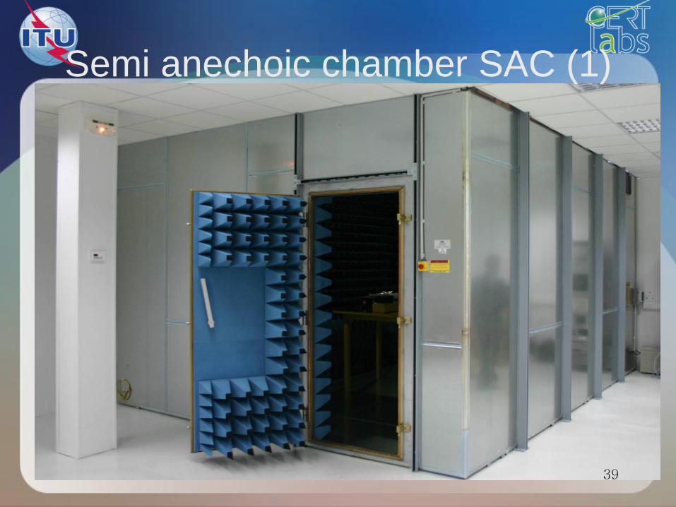
Semi anechoic chamber SAC (1)
39
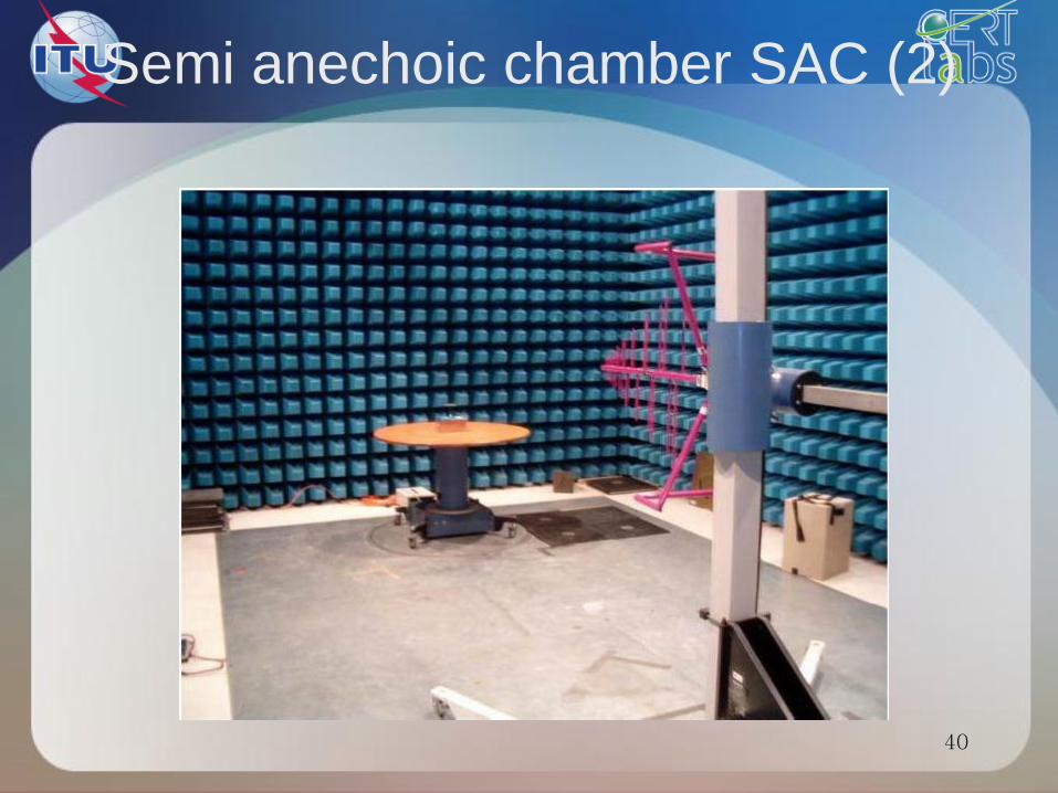
Semi anechoic chamber SAC (2)
40
41
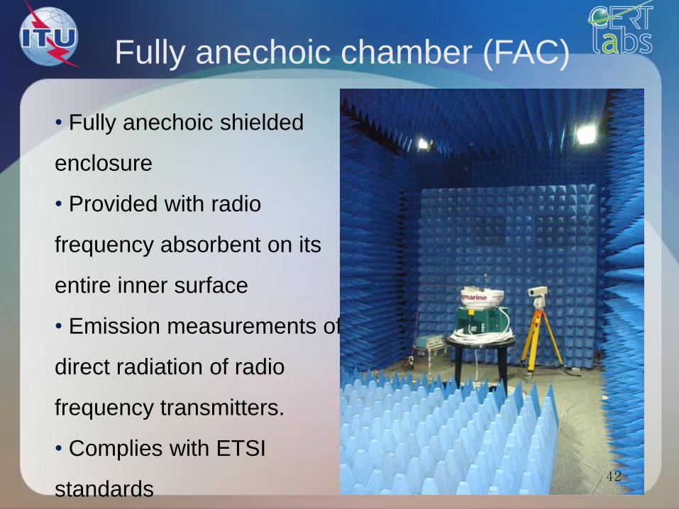
Fully anechoic chamber (FAC)
• Fully anechoic shielded
enclosure
• Provided with radio
frequency absorbent on its
entire inner surface
• Emission measurements of
direct radiation of radio
frequency transmitters.
• Complies with ETSI
standards 42
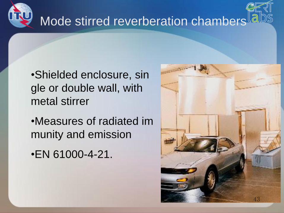
•Shielded enclosure, sin
gle or double wall, with
metal stirrer
•Measures of radiated im
munity and emission
•EN 61000-4-21.
Mode stirred reverberation chambers
43
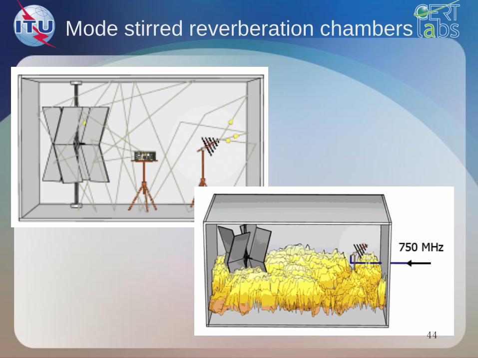
Mode stirred reverberation chambers
44
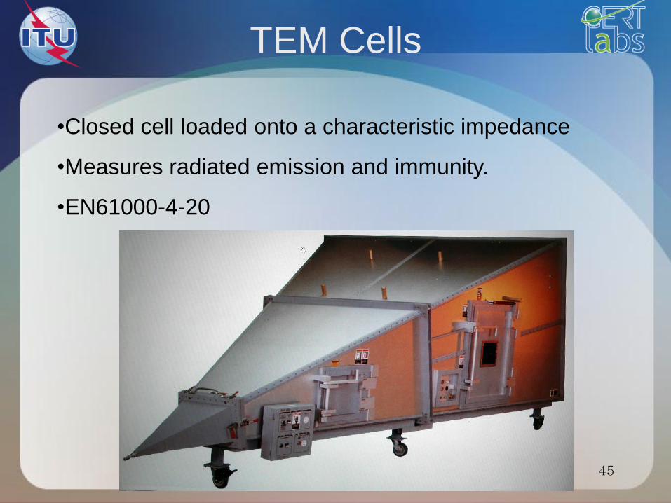
TEM Cells
•Closed cell loaded onto a characteristic impedance
•Measures radiated emission and immunity.
•EN61000-4-20
45
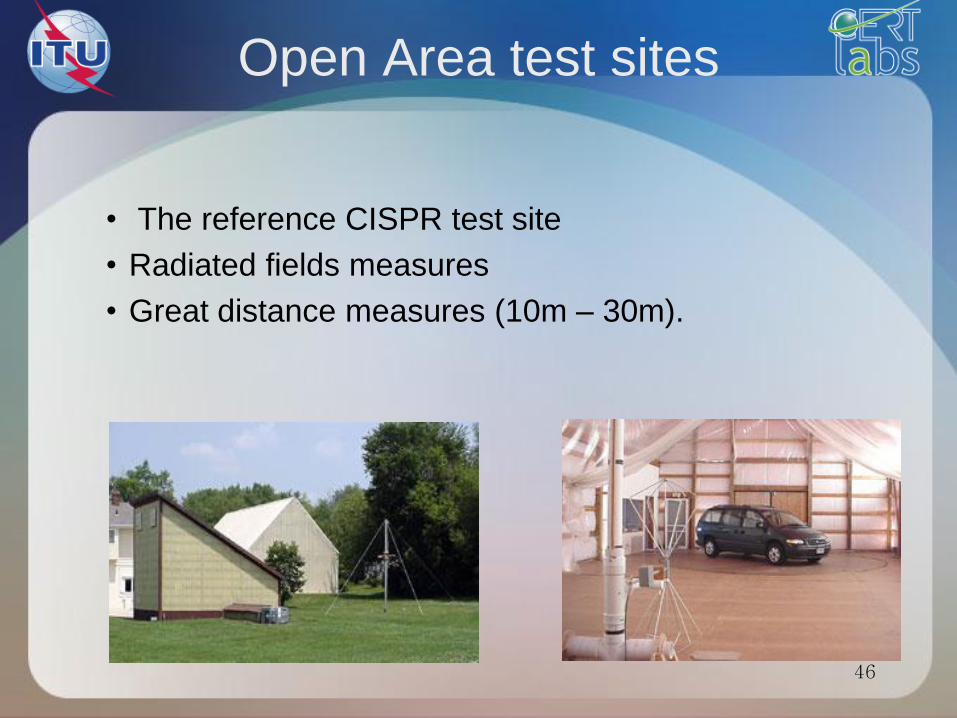
Open Area test sites
• The reference CISPR test site
• Radiated fields measures
• Great distance measures (10m – 30m).
46
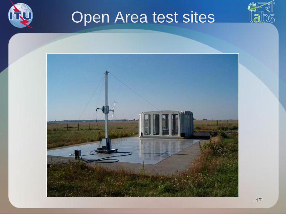
Open Area test sites
47
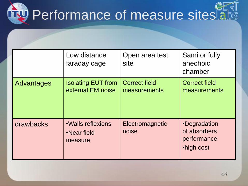
Performance of measure sites
Low distance
faraday cage
Open area test
site
Sami or fully
anechoic
chamber
Advantages Isolating EUT from
external EM noise
Correct field
measurements
Correct field
measurements
drawbacks •Walls reflexions
•Near field
measure
Electromagnetic
noise
•Degradation
of absorbers
performance
•high cost
48
EMC standards
49
Fundamental standards
• These are standards or guidelines that define the
general requirements for the "EMC" (phenomena,
testing ...).
• They apply to all products and are used as
references to develop specific standards.
• They include: the description of electromagnetic phenomena
the characteristics of measuring instruments and of
generation of test signals
the implementation of testing
the recommendations of severity levels
general criteria for proper operation. 50
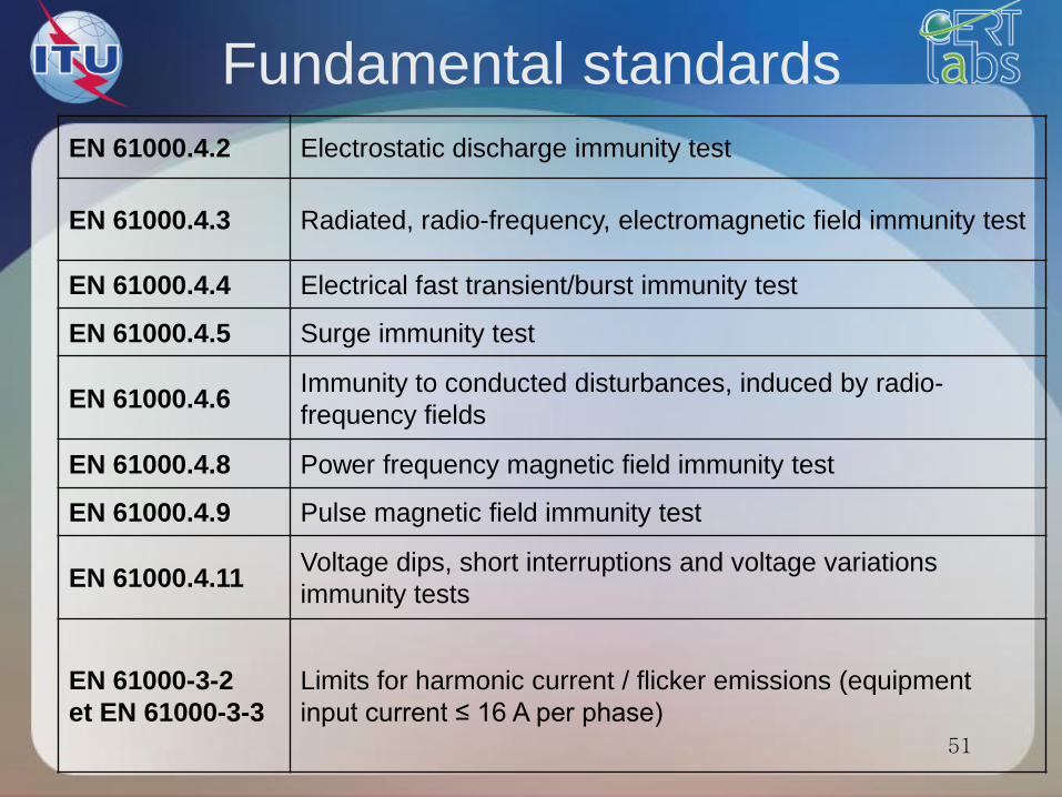
Fundamental standards
EN 61000.4.2 Electrostatic discharge immunity test
EN 61000.4.3 Radiated, radio-frequency, electromagnetic field immunity test
EN 61000.4.4 Electrical fast transient/burst immunity test
EN 61000.4.5 Surge immunity test
EN 61000.4.6 Immunity to conducted disturbances, induced by radio-
frequency fields
EN 61000.4.8 Power frequency magnetic field immunity test
EN 61000.4.9 Pulse magnetic field immunity test
EN 61000.4.11 Voltage dips, short interruptions and voltage variations
immunity tests
EN 61000-3-2
et EN 61000-3-3
Limits for harmonic current / flicker emissions (equipment
input current ≤ 16 A per phase)
51
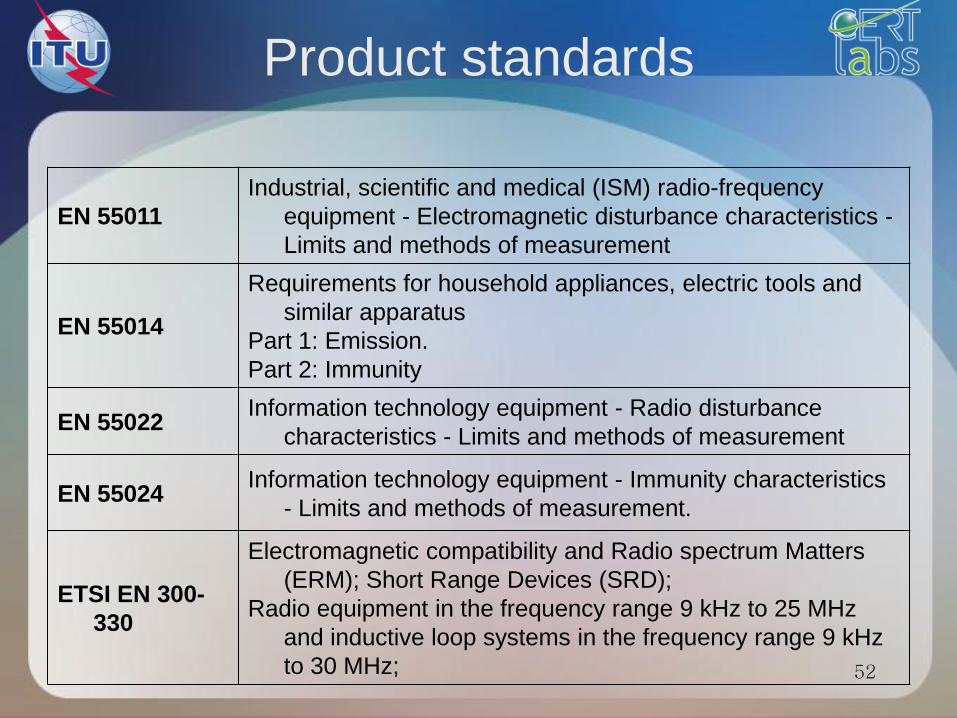
Product standards
EN 55011
Industrial, scientific and medical (ISM) radio-frequency
equipment - Electromagnetic disturbance characteristics -
Limits and methods of measurement
EN 55014
Requirements for household appliances, electric tools and
similar apparatus
Part 1: Emission.
Part 2: Immunity
EN 55022 Information technology equipment - Radio disturbance
characteristics - Limits and methods of measurement
EN 55024 Information technology equipment - Immunity characteristics
- Limits and methods of measurement.
ETSI EN 300-
330
Electromagnetic compatibility and Radio spectrum Matters
(ERM); Short Range Devices (SRD);
Radio equipment in the frequency range 9 kHz to 25 MHz
and inductive loop systems in the frequency range 9 kHz
to 30 MHz; 52
• These standards define, for products or
product families , the special design,
characteristics, methods and test levels.
• Where available, these standards take
precedence over generic standards.
• They use the fundamental standards.
• They define:
tests to be performed
levels of severity of tests
the criteria for proper operation
53
Generic standards
• These standards define the essential requirements in terms of level to be maintained by
type of test
• In the absence of product or family product
standards, they apply to products installed in a defined environment (industrial, residential).
• They use the fundamental standards.
• They define: the environment (residential, industrial ...)
tests to be performed
levels of severity of tests
the performance criteria
54
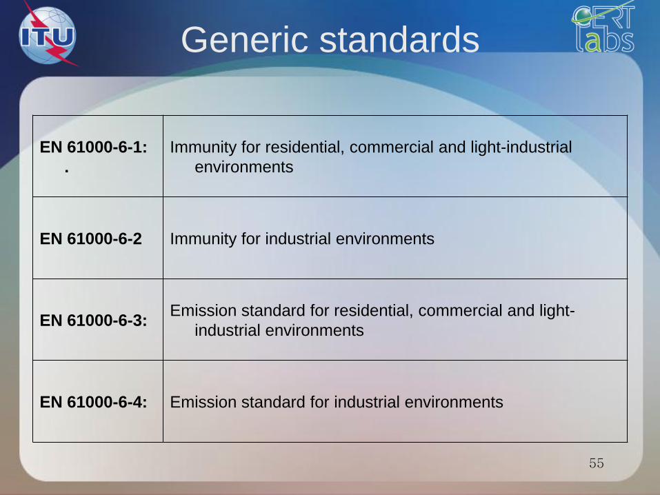
Generic standards
EN 61000-6-1:
.
Immunity for residential, commercial and light-industrial
environments
EN 61000-6-2 Immunity for industrial environments
EN 61000-6-3: Emission standard for residential, commercial and light-
industrial environments
EN 61000-6-4: Emission standard for industrial environments
55
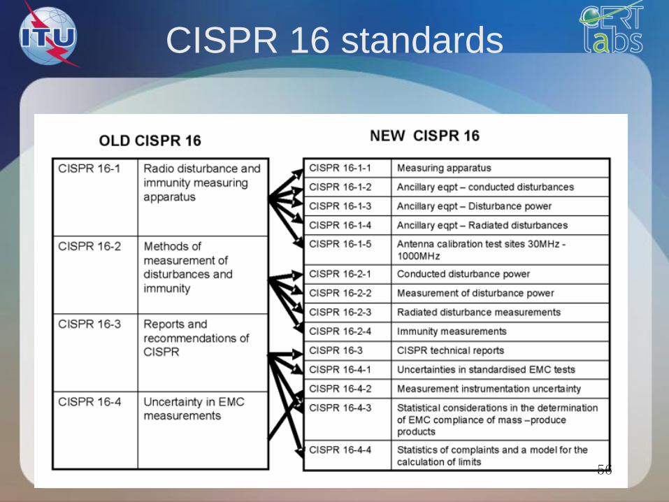
CISPR 16 standards
56
EMC fundamentals
57
ITU Training on Conformance and Interoperability
for AFR Regions
CERT, 28 October – 1st November 2013, Tunis