![1 Convolutional Polar Codes - arXiv · 1 Convolutional Polar Codes Andrew James Ferris, Christoph Hirche and David Poulin Abstract Arikan’s Polar codes [1] attracted much attention](https://static.fdocument.org/doc/165x107/5f07505c7e708231d41c5eb5/1-convolutional-polar-codes-arxiv-1-convolutional-polar-codes-andrew-james-ferris.jpg)
SemanticWebforRobots - Christoph...
154
Semantic Web for Robots Applying Semantic Web technologies for interoperability between virtual worlds and real robots Alex Juarez
Transcript of SemanticWebforRobots - Christoph...
Semantic Web for Robots
Applying Semantic Web technologiesfor interoperability between virtualworlds and real robots
Alex Juarez

Typeset with LATEX2εCover Design by Alex Juarez
c©Alex Juarez 2012. All rights reserved. A catalogue record is available from the Ein-dhoven University of Technology Library.
Proefontwerp Technische Universiteit Eindhoven
ISBN: 000000000-000
Trefw.:Systems Design, Semantic Web, Knowledge Engineering, Robotics, Ontologies
Semantic Web for Robots
Applying Semantic Web technologies for interoperability between virtualworlds and real robots
PROEFONTWERP
ter verkrijging van de graad van doctor
aan de Technische Universiteit Eindhoven,
op gezag van de rector magnificus, prof.dr.ir. C.J. van Duijn,
voor een commissie aangewezen door het College voor Promoties
in het openbaar te verdedigen opdonderdag 15 Maart 2012 om 16:00 uur
door
Alex Juarez
geboren te San Salvador, El Salvador

De documentatie van het proefontwerp is goedgekeurd door de promotor:
prof.dr.ir. L.M.G. Feijs
Copromotoren:
dr. J. Hu PDEng MEng
en
dr. C. Bartneck MTD

Acknowledgements
i

Contents
Acknowledgements i
List of Figures v
List of Tables vii
1 Introduction 1
1.1 Interoperability in a broader context . . . . . . . . . . . . . . . . . . . . . 6
1.2 Assumptions and limitations . . . . . . . . . . . . . . . . . . . . . . . . . . 8
1.3 Research goals . . . . . . . . . . . . . . . . . . . . . . . . . . . . . . . . . 9
1.3.1 Research questions . . . . . . . . . . . . . . . . . . . . . . . . . . 9
1.4 Design process and methodology . . . . . . . . . . . . . . . . . . . . . . . 10
1.4.1 Iterative design (spiral model) . . . . . . . . . . . . . . . . . . . . . 12
1.5 Outline of this document . . . . . . . . . . . . . . . . . . . . . . . . . . . 13
2 Related work 15
2.1 Bridging virtual and real worlds . . . . . . . . . . . . . . . . . . . . . . . . 17
2.1.1 Virtualized reality . . . . . . . . . . . . . . . . . . . . . . . . . . . 17
2.1.2 Mixed reality . . . . . . . . . . . . . . . . . . . . . . . . . . . . . . 17
2.2 Cross-reality . . . . . . . . . . . . . . . . . . . . . . . . . . . . . . . . . . 19
2.3 Cross-reality and robotics . . . . . . . . . . . . . . . . . . . . . . . . . . . 19
2.4 Creating knowledge about robots . . . . . . . . . . . . . . . . . . . . . . . 22
3 Requirements and concepts 27
3.1 RoboDB . . . . . . . . . . . . . . . . . . . . . . . . . . . . . . . . . . . . 27
3.1.1 Functional requirements for RoboDB . . . . . . . . . . . . . . . . . 28
3.1.2 Technical requirements . . . . . . . . . . . . . . . . . . . . . . . . 29
3.2 PAC4 . . . . . . . . . . . . . . . . . . . . . . . . . . . . . . . . . . . . . . 30
3.2.1 Functional requirements . . . . . . . . . . . . . . . . . . . . . . . . 31
3.2.2 Technical requirements . . . . . . . . . . . . . . . . . . . . . . . . 31
4 From data to information: RoboDB 33
4.1 Data format selection . . . . . . . . . . . . . . . . . . . . . . . . . . . . . 33
4.2 Software tools selection . . . . . . . . . . . . . . . . . . . . . . . . . . . . 36
4.3 RoboDB system architecture . . . . . . . . . . . . . . . . . . . . . . . . . 40
4.4 RoboDB implementation . . . . . . . . . . . . . . . . . . . . . . . . . . . 43
4.4.1 Creating robot descriptions using Semantic Mediawiki . . . . . . . . 43
iii
Contents
4.4.2 Second RoboDB prototype . . . . . . . . . . . . . . . . . . . . . . 49
4.4.3 Usability evaluation . . . . . . . . . . . . . . . . . . . . . . . . . . 53
4.5 Content authoring in RoboDB . . . . . . . . . . . . . . . . . . . . . . . . 56
4.6 Concluding remarks . . . . . . . . . . . . . . . . . . . . . . . . . . . . . . 58
5 Knowledge engineering 59
5.1 Ontologies and the Semantic Web . . . . . . . . . . . . . . . . . . . . . . 59
5.2 Description Logics . . . . . . . . . . . . . . . . . . . . . . . . . . . . . . . 60
5.3 Ontology design . . . . . . . . . . . . . . . . . . . . . . . . . . . . . . . . 63
5.4 Modelling robot capabilities . . . . . . . . . . . . . . . . . . . . . . . . . . 64
5.4.1 Related work . . . . . . . . . . . . . . . . . . . . . . . . . . . . . . 65
5.4.2 Implementation . . . . . . . . . . . . . . . . . . . . . . . . . . . . 67
5.4.3 Using the robot capability descriptions . . . . . . . . . . . . . . . . 73
5.5 Case study: ROILAbot . . . . . . . . . . . . . . . . . . . . . . . . . . . . 74
5.6 Adding capability modelling to RoboDB . . . . . . . . . . . . . . . . . . . 81
5.7 Concluding remarks . . . . . . . . . . . . . . . . . . . . . . . . . . . . . . 82
6 PAC4 85
6.1 MPEG-V . . . . . . . . . . . . . . . . . . . . . . . . . . . . . . . . . . . . 86
6.2 System design and implementation . . . . . . . . . . . . . . . . . . . . . . 92
6.3 Evaluation: Virtual Presence . . . . . . . . . . . . . . . . . . . . . . . . . 94
6.3.1 The IPO-Social Presence Questionnaire . . . . . . . . . . . . . . . 95
6.3.2 Experimental setup . . . . . . . . . . . . . . . . . . . . . . . . . . 95
6.3.3 Experiment design . . . . . . . . . . . . . . . . . . . . . . . . . . . 96
6.3.4 User experiment . . . . . . . . . . . . . . . . . . . . . . . . . . . . 96
6.3.5 Experiment results . . . . . . . . . . . . . . . . . . . . . . . . . . . 97
6.3.6 Discussion . . . . . . . . . . . . . . . . . . . . . . . . . . . . . . . 100
6.4 Concluding remarks . . . . . . . . . . . . . . . . . . . . . . . . . . . . . . 100
7 Conclusions 103
Bibliography 109
A RoboNed Letter 119
B Built-in knowledge base glossary 121
C XML schema definitions for MPEG-V data structures 125
D PAC4 class diagram 131
E PAC4 User Evaluation Questionnaires 133
F List of publications 137
G Summary 139
H Curriculum Vitae 141
iv
List of Figures
1.1 Examples of virtual worlds evolution . . . . . . . . . . . . . . . . . . . . . . . 3
1.2 Broad view of interoperability between virtual worlds and real devices. Solid lines
represent systems interoperability while dashed lines represent the interaction
with human users. For clarity, not all possible connections have been drawn in
this diagram. . . . . . . . . . . . . . . . . . . . . . . . . . . . . . . . . . . . . 5
1.3 Different entities and their relationships in the conceptual design. . . . . . . . 11
1.4 Iterative design (spiral model) . . . . . . . . . . . . . . . . . . . . . . . . . . . 13
2.1 Example of the combination 3D modelling and web technologies in the Google
Body application . . . . . . . . . . . . . . . . . . . . . . . . . . . . . . . . . . 16
2.2 Representation of the virtuality continuum as appeared in [Milgram and Kishino,
1994] . . . . . . . . . . . . . . . . . . . . . . . . . . . . . . . . . . . . . . . 18
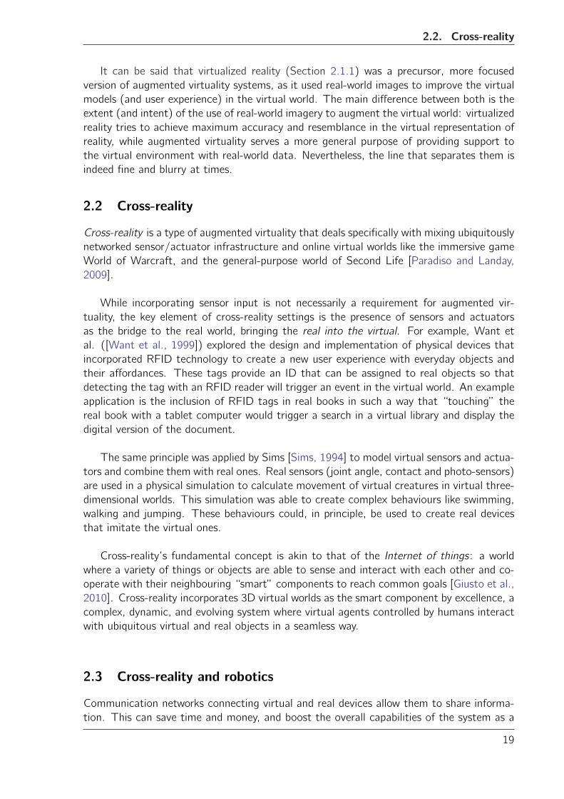
2.3 The CibercityWalker augmented virtuality system. . . . . . . . . . . . . . . . . 18
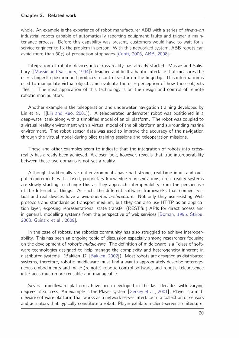
2.4 Player system architecture as appeared in [Gerkey et al., 2001] . . . . . . . . 21
2.5 SURF software architecture as appeared in [Ha et al., 2005] . . . . . . . . . . 23
2.6 RoboEarth robot architecture as appeared in [Zweigle et al., 2009] . . . . . . 25
3.1 Overview of Semantic Web Technologies and their relationship. (Available on-
line at www.w3.org) . . . . . . . . . . . . . . . . . . . . . . . . . . . . . . . . 29
4.1 Snapshot of Protege’s GUI. . . . . . . . . . . . . . . . . . . . . . . . . . . . 38
4.2 Snapshot of Semantic Mediawiki (SMW) GUI. . . . . . . . . . . . . . . . . . 39
4.3 Mediawiki framework general architecture . . . . . . . . . . . . . . . . . . . . 40
4.4 Semantic Mediawiki (SMW) framework general architecture . . . . . . . . . . 42
4.5 RoboDB system architecture . . . . . . . . . . . . . . . . . . . . . . . . . . . 43
4.6 AdMoVeo robot developed at Eindhoven University of Technology . . . . . . . 44
4.7 AdMoVeo physical structure in SMW pages and annotations . . . . . . . . . . 44
4.8 Original workflow used to create a description of the robot structure . . . . . . 46
4.9 Snapshot of the user interface to create the robot structure during the first
iteration prototype . . . . . . . . . . . . . . . . . . . . . . . . . . . . . . . . . 47
4.10 Example of two iterations of GUI design for RoboDB. . . . . . . . . . . . . . . 49
4.11 Screenshot of the interactive application to create a robot’s structural description 50
4.12 Individual SUS scores distribution . . . . . . . . . . . . . . . . . . . . . . . . . 55
4.13 Individual adjective scale evaluation . . . . . . . . . . . . . . . . . . . . . . . . 55
5.1 Example of two individuals in the robot domain . . . . . . . . . . . . . . . . . 62
5.2 Built-in knowledge base stored in the ontology used by RoboDB . . . . . . . . 65
v
List of Figures
5.3 Top level of service ontology as appeared in the OWL-S overview document . . 67
5.4 Robot used in the case study . . . . . . . . . . . . . . . . . . . . . . . . . . . 75
5.5 Information access in the ROILAbot case study . . . . . . . . . . . . . . . . . 76
5.6 Dialogs to select and use robots capabilities in the virtual world . . . . . . . . 80
5.7 Screenshot of the English-to-ROILA translation ontology . . . . . . . . . . . . 81
5.8 Modelling the DrivingCapability entity in RoboDB . . . . . . . . . . . . . . . . 83
6.1 Class diagram of the Observer pattern . . . . . . . . . . . . . . . . . . . . . . 93
6.2 PAC4 class diagram . . . . . . . . . . . . . . . . . . . . . . . . . . . . . . . . 93
6.3 Sequence diagram showing entity interactions in PAC4 . . . . . . . . . . . . . 94
6.4 Real room located in the Context Lab and its virtual counterpart in Second Life. 95
6.5 Mean scores of the overall level of presence experienced by the participants while
using PAC4 vs plain Second Life . . . . . . . . . . . . . . . . . . . . . . . . . 98
6.6 Mean scores of the semantic differential level of presence experienced by the
participants while using PAC4 vs plain Second Life . . . . . . . . . . . . . . . 99
6.7 Mean scores of the agree-disagree level of presence experienced by the partici-
pants while using PAC4 vs plain Second Life . . . . . . . . . . . . . . . . . . . 99
D.1 PAC4 class diagram . . . . . . . . . . . . . . . . . . . . . . . . . . . . . . . . 132
vi
List of Tables
4.1 Overview of knowledge encoding data formats considered for RoboDB . . . . . 37
4.2 Overview of Semantic Web software tools . . . . . . . . . . . . . . . . . . . . 41
4.3 Data types currently defined in RoboDB . . . . . . . . . . . . . . . . . . . . . 51
4.4 Properties and facts distribution by data type . . . . . . . . . . . . . . . . . . 51
4.5 Most popular embodiment parts . . . . . . . . . . . . . . . . . . . . . . . . . 52
4.6 Least frequent embodiment parts . . . . . . . . . . . . . . . . . . . . . . . . . 52
4.7 Average SUS score and adjective scale results with their corresponding standard
deviation . . . . . . . . . . . . . . . . . . . . . . . . . . . . . . . . . . . . . . 54
5.1 Original set of properties defined in the ontology . . . . . . . . . . . . . . . . 63
5.2 Extended set of properties defined in the ontology to implement the Dutch
robotics directory . . . . . . . . . . . . . . . . . . . . . . . . . . . . . . . . . 64
6.1 MPEG-V contribution requirements . . . . . . . . . . . . . . . . . . . . . . . 89
6.2 Semantics of the EmbodimentDescription element . . . . . . . . . . . . . . . . 90
6.3 Semantics of the RobotMessageData element . . . . . . . . . . . . . . . . . . 91
vii

Chapter
1Introduction
Interoperability is a topic that is at the core of technological advancement. It is also one of
the main activities of several organizations like the International Organization for Standard-
ization (ISO1), or the World Wide Web Consortium (W3C2). These and other organizations
dedicate considerable resources to the research and development of interoperability plat-
forms meant to enable the seamless interaction between heterogeneous, distributed systems.
Metaverse1 was a European research project that investigated the creation of global
standards between virtual and real worlds. The project consortium includes more than 40
partners from academia and industry, distributed over 7 countries across Europe. Research
efforts in Metaverse1 were mainly focused on two avenues: interoperability between virtual
worlds and interoperability in cross-reality environments.
The topic of this PhD project was defined in the context of Metaverse1 and the research
on interoperability in cross-realities. Cross-reality is a term that defines mixed reality en-
vironments that tunnel dense real-world data acquired through the use of sensor/actuator
device networks into virtual worlds [Paradiso and Landay, 2009].
‘Virtual world’ is a term that applies to online communities that take the form of com-
puter simulated environments, representing physical places and situations from the real
world as well as from imaginary worlds, and where users can interact and create content
themselves [Bartle, 2004]. A software agent is a “component of software and/or hard-
ware which is capable of acting exactingly in order to accomplish tasks on behalf of its
user” [Nwana, 1996]. Virtual agents are software agents that function as interface for the
virtual world user. Virtual agents may also be related to a (3D) virtual object or avatar.
1http://www.iso.org2http://www.w3.org/
1
Chapter 1. Introduction
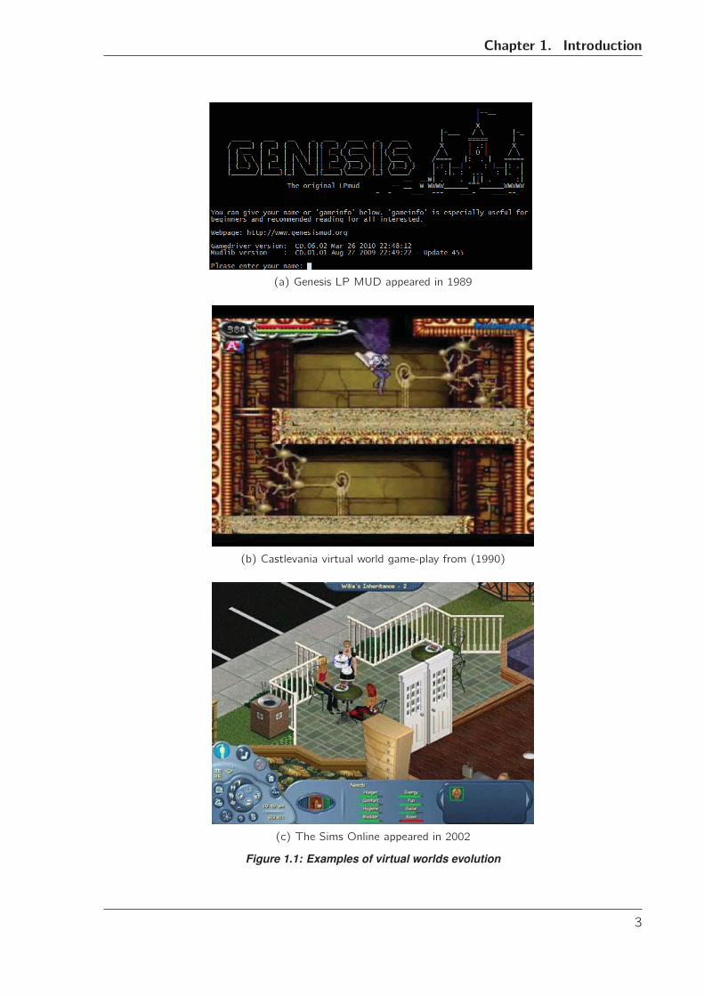
Virtual worlds originated from interactive gaming platforms [Bartle, 2004] and there-
fore, they retain to this day some of the terminology associated to gaming environments,
e.g. game-play and game-scripts (or simply “scripts”). As the gaming industry evolved
virtual worlds did so too, with the first text-based chatroom-like “worlds” turning into 2D
environments, and later evolving into 3D modelled worlds. Figure 1.1 shows three examples
of virtual worlds from different eras.
Nowadays, the term virtual world is mostly associated with virtual reality and 3D repre-
sentations of places where the imaginary meets the real and the environment develops and
evolves continuously, usually in an open-ended way (e.g. Second Life, Blue Mars, IMVU).
However, a broader, more general interpretation of the definition encompasses a large
range of applications including virtual reality, (3D) video games, and even social networks
like Facebook or Google+.
It is important to point out that while early virtual worlds were confined to relatively
small communities in “closed” computer networks, current virtual worlds rely heavily on the
World Wide Web and other Internet systems as a medium for communication and operation.
Furthermore, the ubiquitous nature of the current Web means that more and more
heterogeneous devices are being connected to, and more services are offered by it. As
a consequence, the value of virtual worlds in the entertainment and gaming business is
increased by the potential social and economic impact of merging and integrating these
virtual and real devices and services. This type of interaction can already be seen in social
networks: Facebook provides means to send text messages (SMS) to mobile phones around
the world, while at the same time, it allows to use camera and microphone devices in a
video chat application, all this without the user ever leaving the virtual realm.
A key component to realize this integration is interoperability [Feijs, 1996]. The ability
to exchange and use information between heterogeneous systems can be studied from two
different perspectives. On the one hand there is a syntactic interoperability that refers to
the way of communicating and exchanging data, using specific data formats and communi-
cation protocols. On the other hand there is a semantic interoperability that refers to the
way meaning is added to the data to turn it into information and ultimately into knowledge
that can be used by different connected systems [Veltman, 2001].
Some of the challenges of interoperability between virtual and real seem to have been
at least partially solved, mostly with respect to syntactic interoperability. For example, the
communication medium used by the vast majority of virtual worlds for data exchange is the
Internet and its associated communication protocols and data formats such as TCP, UDP,
XML, etc. At the same time, real world devices are gradually adopting this data exchange
infrastructure: entertainment systems like the AppleTV [Apple Inc., 2007] and robotic sys-
tems like the Nao humanoid robot [Gouaillier et al., 2009] are some examples of the new
generation of connected devices that can, in principle, make the goal of interoperability a
reality.
2
Chapter 1. Introduction
(a) Genesis LP MUD appeared in 1989
(b) Castlevania virtual world game-play from (1990)
(c) The Sims Online appeared in 2002
Figure 1.1: Examples of virtual worlds evolution
3
Chapter 1. Introduction
However, a closer look at these devices reveals that interoperability is limited or non-
existent. While the Nao robot and the Apple TV can indeed connect to the Internet using
TCP/IP communication protocols, a Web software agent that wants to access their capa-
bilities must know the appropriate syntax of their API function calls. This syntax will vary
greatly between the devices, even for similar functional capabilities present in both devices,
e.g. video streaming. With limited syntactic interoperability, the importance of the seman-
tic interoperability increases. The software agent trying to access the capabilities of these
devices will need to know what the intended use of the capability is, what conditions are
needed for operation/use of those capabilities, what parameters are required, and what can
be expected from the capability execution. In most cases this information is not available
to the software agent, and it is up to the human programmer to embed this information in
the agent’s source code.
Tim Berners-Lee, the father of the Web, is a strong advocate for semantic interoperabil-
ity. He coined the term Semantic Web to describe an extension of the current Web where
information is given a well-defined meaning, bringing structure to the data, and enabling
software agents to create knowledge without the need for large-scale artificial intelligence
[Berners-Lee et al., 2001]. While many technologies to realize this vision already exist and
many other are in development, the real power of the Semantic Web will be realized only
when people create programs that collect content from different sources, process the in-
formation, and exchange the results with other programs.
Breaking out of the virtual realm and seamlessly interoperating with real devices can
bring important changes in many disciplines. One of these disciplines is robotics. Tradi-
tionally, robots have been used in high precision applications like industrial manufacturing
and medical surgery. However, nowadays robots are also gaining a place at home: robotic
vacuum cleaners keep dust away from house floors while robot pets and toys take the role of
companions and entertainers. Furthermore, Human-Robot Interaction research has shown
that robot companions are getting more acceptance as assistants or servants, preferably to
take care of household tasks [Dautenhahn et al., 2005].
Combining virtual worlds and real robots has potential applications in simulation, remote
communication and monitoring, and robot teleoperation. An example is the study by Lin
et al. [Lin and Kuo, 2001] where a virtual underwater world is used to enhance the sensory
information received from a teleoperated underwater robot. This information is used to
provide real-life-like feedback and improve pilot training. It is not difficult to imagine other
situations where virtual worlds are used as “remote consoles” to control a robot companion
and interact with people and other devices at a distance, like it is done with the robot
Nabaztag (now called Karotz3).
The question is then: Why has interoperability not been achieved yet? Why don’t we
see more of these applications in real life? One of the reasons is the mismatch between the
design and operation of robotic systems and the design and paradigms of Internet-oriented
applications such as virtual worlds.
3http://www.karotz.com/
4
Chapter 1. Introduction
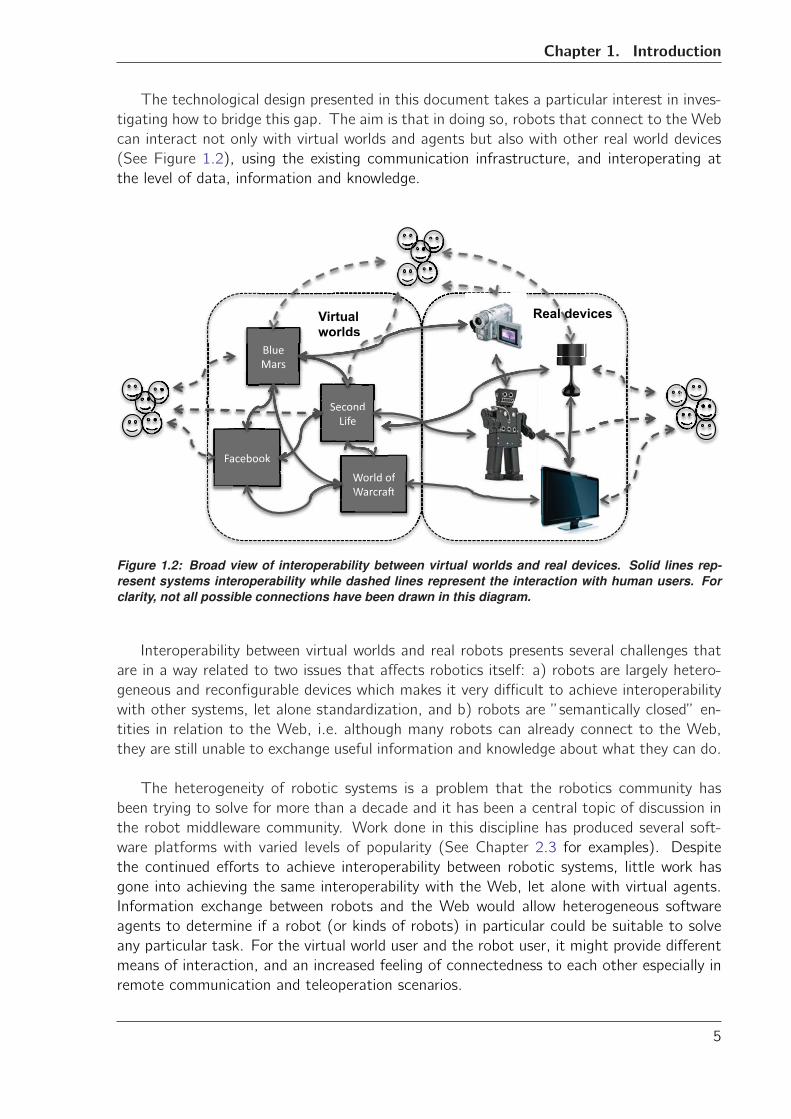
The technological design presented in this document takes a particular interest in inves-
tigating how to bridge this gap. The aim is that in doing so, robots that connect to the Web
can interact not only with virtual worlds and agents but also with other real world devices
(See Figure 1.2), using the existing communication infrastructure, and interoperating at
the level of data, information and knowledge.
����������
� �������
������ ���
���������� ��� ��
�
������
�
��
��
���
��
Virtual worlds
Real devices
�
�
ViVirwo
Real devt lrtual orlds
Figure 1.2: Broad view of interoperability between virtual worlds and real devices. Solid lines rep-resent systems interoperability while dashed lines represent the interaction with human users. Forclarity, not all possible connections have been drawn in this diagram.
Interoperability between virtual worlds and real robots presents several challenges that
are in a way related to two issues that affects robotics itself: a) robots are largely hetero-
geneous and reconfigurable devices which makes it very difficult to achieve interoperability
with other systems, let alone standardization, and b) robots are ”semantically closed” en-
tities in relation to the Web, i.e. although many robots can already connect to the Web,
they are still unable to exchange useful information and knowledge about what they can do.
The heterogeneity of robotic systems is a problem that the robotics community has
been trying to solve for more than a decade and it has been a central topic of discussion in
the robot middleware community. Work done in this discipline has produced several soft-
ware platforms with varied levels of popularity (See Chapter 2.3 for examples). Despite
the continued efforts to achieve interoperability between robotic systems, little work has
gone into achieving the same interoperability with the Web, let alone with virtual agents.
Information exchange between robots and the Web would allow heterogeneous software
agents to determine if a robot (or kinds of robots) in particular could be suitable to solve
any particular task. For the virtual world user and the robot user, it might provide different
means of interaction, and an increased feeling of connectedness to each other especially in
remote communication and teleoperation scenarios.
5
Chapter 1. Introduction
It is evident that the vision and concepts of the Semantic Web become very relevant
to achieve robots-virtual worlds interoperability. The universality and versatility of Seman-
tic Web systems, together with the structure and reasoning capabilities over distributed
information, provide a sound framework that interoperability can be built upon. Knowl-
edge about robots and their capabilities can be expressed in a language that virtual agents
can understand. Conversely, access to virtual agents, their properties and services can
also be made available to real devices. The semantic level ensures flexibility towards the
future: interoperability that relies heavily on the syntactical level depends on standardiza-
tion processes that cannot anticipate all possible future needs. Complementing syntactic
interoperability with semantics offers possibilities of reaching agreements and shared under-
standing of concepts, and even the bootstrapping of new reasoning capabilities as people
generate new information and semantic agents discover new knowledge.
1.1 Interoperability in a broader context
The beginning of this chapter pointed out the importance of interoperability and the tech-
nical challenges it poses. However, interoperability has a much broader context where the
seamless exchange of information between devices and applications can have an impact in
society.
An example of how interoperability can change the way people interact is the Internet
itself. From the early electronic mail messaging and chat applications based on the Internet
Relay Chat Protocol 4 to today’s advanced VoIP and video conferencing applications, the
Internet and the technologies based on it have transformed the way people communicate
and relate to each other. These technologies also have had a direct impact in more tradi-
tional forms of communication and services like landline telephony, television broadcasting,
postal services, and bank services, which are transformed and sometimes even replaced by
their digital counterparts.
The vision guiding the research presented in this document is that enabling interoper-
ability between virtual worlds and real robots will have a positive impact, not only for virtual
worlds and robotics, but also for human-robot interaction with innovative applications in
many fields.
Virtual worlds is a growing industry. In 2009 there were approximately 150 different
virtual worlds with a total of 50 million subscribers, producing a revenue of 2 billion USD.
For 2012, the projected figures show approximately 800 different virtual worlds totalling 250
million subscribers and producing a revenue of 6 billion USD (estimates according to KZero
Worldswide 5). However, the value of virtual worlds is not only commercial as argued by
Hu and Offermans in [Hu and Offermans, 2009]. Virtual worlds have considerable potential
in social and economic research as they provide opportunities to setup virtual laboratories
for online experiments that are scalable, cross socio-cultural boundaries, and are sustainable
for longer periods of time than with traditional experiment modalities [Bainbridge, 2007].
Virtual worlds also have potential application in education, enhancing the learning experi-
4http://www.irchelp.org5http://www.kzero.co.uk
6
1.1. Interoperability in a broader context
ence of students. Virtual worlds provide spaces for creative learning, as well as technologies
for distance learning, and the possibility to reach older people and people with physical
disabilities [Boulos et al., 2007]. There are already examples of educational applications
developed in 3D virtual worlds like the Loyalist College6 and the Open University Centre7
in Second Life.
Robotics, on the other hand, is a more developed and established industry. Through
several decades of technological research and development, robotics has positioned itself at
the core of manufacturing and production processes. From food processing and packaging
to automobile assembly lines, robotic devices have had an impact on the increasingly au-
tomated production of goods, and therefore, in how people use and consume those goods.
Nowadays robotics is struggling to enter the domestic and service markets. So far it is
mostly as household appliances and toys, for example the Roomba vacuum cleaner8 or the
RoboSapiens humanoid toy 9. However, there are considerable research efforts being spent
on developing robots as helpers, carers, and companions.
Enabling interoperability between virtual worlds an real robots would allow to combine
the strengths of each discipline, giving birth to innovative, interesting applications. For
example virtual representations of real environments could be generated online or offline,
using the information from robot sensors to create virtual object and surfaces in a 3D
virtual world. Such application could be used in search and rescue situations, e.g. in the
creation of improved, more realistic simulations for training of remote robot operators in
disaster scenarios. One can only begin to realize the potential impact of any improvement
in search and rescue simulations if one considers that more than 1.1 million people were
killed in urban disasters between 2000 and 200910. Robot operators that have been trained
in dynamic, realistic disaster simulation scenarios could make the difference between life and
death for many of the victims. Combining virtual worlds and real robots also has a potential
application in space exploration scenarios to visualize in a more realistic manner the findings
of robotic vehicles during their missions on other planets. This application could also be
used to design future versions of space exploration vehicles, and to train robot operators to
control the robotic vehicle during missions. Virtual reality has been used in telepresence ap-
plications in health care, e.g. augmented reality surgery, planning and simulation procedures
pre- and post-surgery, and medical therapy [Mohne, 1997]. As health care services become
more expensive and scarce, connecting modern 3D virtual worlds to a new generation of
human-friendly, safe domestic robots, intelligent devices, and wearable sensors can origi-
nate a new range of telepresence and remote care applications. For example, a virtual world
application that recreates the home environment of a patient could be used by the health
care professional as a sort of “personalized monitoring room”, from which he/she could
verify the general health status of the patient -sugar levels, blood pressure,etc.-, while at
the same time command the robot to bring food and medicines to the patient. Visualizing
in the virtual world the real world sensor information, and interacting with the real robot
6http://www.loyalistcollege.com/7http://www8.open.ac.uk8http://www.irobot.com9http://www.wowwee.com/en/products/toys/robots/robotics/robosapiens10World Disaster Report. - Available online at http://www.ifrc.org/en/publications-and-reports/
world-disasters-report/report-online/
7
Chapter 1. Introduction
and other devices using “virtual objects” would provide the health care provider with a more
meaningful feedback than traditional video or audio alone. The impact of such applications
in society would be considerable: patients would regain some of their independence by being
able get appropriate care at home, while care professionals could do their job in an efficient
manner.
It is important to notice that many factors other than interoperability alone will play
a role in realizing this vision, e.g. safety, usability, privacy, user acceptance, and industry
support. While at the moment it is not possible to know which of the envisioned appli-
cations and systems may come to happen, the work presented in this technological design
documentation constitutes the first steps toward achieving the necessary interoperability
between the virtual world and robotics domains.
1.2 Assumptions and limitations
The insights presented before illustrate the many challenges and research opportunities in
the topic of interoperability between virtual and real worlds. Addressing all these challenges
is impractical in view of the limited amount of time available to complete the PhD project.
Therefore, there is a need to narrow down the scope of the technological design presented
in this document by imposing a series of assumptions and limitations. The basic set of
assumptions is:
I 2D and 3D virtual environments are valuable. The intrinsic value of virtual worlds has
been proven during the years by their use not only in the gaming and entertainment
industry, but also in simulation, education, and training [De Freitas, 2008]. Therefore,
this technological design investigates the added value of connecting virtual worlds and
real robots.
II Robots that care about and play with their users are valuable. Robotics research has
repeatedly shown the importance of robots as companions, helpers and social mediators
with people [Dautenhahn, 1999]. Therefore, it is admissible to accept their value as
a given and concentrate on the interactions of virtual world users with remote robots
and robot users.
III Semantic Web technologies are a proven, scalable way of representing knowledge on the
Web. The Semantic Web has indeed reached a level of maturity reflected in powerful
knowledge representations like OWL [OWL, 2004] and numerous storage and reasoning
engines like SAOR [Hogan et al., 2009] or Minerva [Zhou et al., 2006]. Examples of
practical applications that implement these technologies are the Gene Ontology11 and
Freebase12. These tools showcase the flexibility and scalability of semantic knowledge
modelling in varied application areas of the Semantic Web.
The limitations to the scope of this PhD project are:
I This project does not intend to create yet another middleware for robotics or a dis-
tributed systems communication framework. Instead it explores mechanisms to make
11http://www.geneontology.org12http://www.freebase.com
8
1.3. Research goals
information about robots available to virtual worlds through the use of established and
upcoming web standards and best practices.
II This project does not work on the design of network communication and transport
protocols, but instead it assumes that both virtual worlds and real robots can connect
to the Web and, when possible, use the different protocols and data formats already
available for basic data exchange.
III This project limits itself to the use of 3D virtual worlds. This decision was made to
align the use cases and application scenarios developed in the PhD project with those
in the Metaverse1 project.
1.3 Research goals
As illustrated previously in this chapter, interoperability between virtual worlds and real
robots is difficult due to the existing gap between the design and interfaces of robotic sys-
tems and the Internet-oriented design of virtual worlds.
This technological design proposes to fill this gap by using Semantic Web technologies.
These technologies enable the creation of knowledge about robots and their capabilities,
and are capable of handling the heterogeneity and high reconfigurability of robotic systems.
Virtual worlds and other web agents can also understand and re-use this knowledge. Aug-
menting virtual worlds with the abilities of real robots can enrich the virtual world itself, as
well as the virtual world user experience.
The focus of this technological design is on three aspects: a) it focuses on the mecha-
nisms necessary to make information about robots available to virtual worlds, enabling the
interaction between them, b) it focuses on the creation, maintenance and use of knowl-
edge about robot capabilities to effectively enhance the virtual world functionality, and c)
it focuses on the virtual world’s user experience with such an enhanced system, in a remote
communication scenario.
1.3.1 Research questions
The research questions that arise are:
1. How do we tackle the problem of capturing the essential aspects of robot heterogene-
ity and robot capabilities and make them available to virtual worlds?
2. Once a method for describing robots has been designed:
• How can knowledge be created about robots in a sustainable, organized, andabove all flexible way, such that it can cope with the evolution of the hardware?
• How can this knowledge be made available and understandable to users that arenot necessarily experts in robotics?
• What are the appropriate technologies that should be used to build a system forthis purpose?
• Who will build this knowledge base?9
Chapter 1. Introduction
3. How will the knowledge about robots and their capabilities help to solve the problem
of enabling interoperability between virtual and real worlds? How can we enable virtual
world users with minimal expertise in robotics to let them:
• Transform robot descriptions into alternative representations (if necessary) thatthe virtual world of their choice can understand.
• Use this knowledge as a blueprint for communication and interaction patternsbetween virtual worlds and real robots.
• (Re)-use these blueprints in their scripts to create content in the virtual worldthat makes use of the functionalities of real robots.
4. When looking at the social aspect of the project:
• What are the characteristics that determine the added value of interoperabilityin the virtual world’s user experience?
• Is it possible that a knowledge system as outlined above can contribute to therobotics community’s struggle for standardization and best practices?
This technological design attempts to answer these questions and in the process, make
a contribution to interoperability between virtual worlds and real robots.
1.4 Design process and methodology
The technological design developed in this document involves several entities. These entities
correspond to the key concepts and systems developed during this PhD project to address
the research questions presented in the previous section:
• RoboDB. Robotic systems are physically heterogeneous and largely reconfigurable.Before attempting to interoperate with these machines, it is desirable to gather knowl-
edge about their physical structure in a structured and sustainable way. This devel-
opment goes to answer research question 1 and partially answers research questions
2 and 3.
• Knowledge engineering tackles the issue of using the information gathered by Ro-boDB to generate technically flexible and usable interfaces that enable interoperabil-
ity between virtual worlds and real robotic systems. The conceptual design of this
element completes the answer to research questions 2 and 3, especially with respect
to the appropriate technology and knowledge representation to create the blueprints
for communication patterns between the two domains.
• PAC4 is a system that takes the output of the knowledge engineering element anduses it to implement a software package that effectively connects a virtual world with
several robotic embodiments. This system is used in an experimental setting using a
socially relevant scenario. This development also answers research questions 3 and 4.
To complete the broader picture of the conceptual design proposed as solution to en-
able interoperability between virtual worlds and real robots, one must consider the different
communities that interact with the different systems developed. The robotics community
10
1.4. Design process and methodology
that develops robotic devices and could benefit from having a repository of robot-related
information and from connecting robots to the virtual realm. Robot users who possess
commercially available robotic devices for multiple purposes like cleaning, assistance, com-
pany, and entertainment. The virtual world users who already are familiar with the different
modalities of the virtual realm like games, open-ended 3D worlds, social networks, etc.
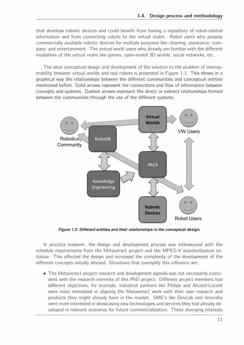
The ideal conceptual design and development of the solution to the problem of interop-
erability between virtual worlds and real robots is presented in Figure 1.3. This shows in a
graphical way the relationships between the different communities and conceptual entities
mentioned before. Solid arrows represent the connections and flow of information between
concepts and systems. Dashed arrows represent the direct or indirect relationships formed
between the communities through the use of the different systems.
�������
����������� ���� ���
�����
�����������
������������
VW Users
Robot Users
Robotics Community
Figure 1.3: Different entities and their relationships in the conceptual design.
In practice however, the design and development process was interweaved with the
schedule requirements from the Metaverse1 project and the MPEG-V standardization ini-
tiative. This affected the design and increased the complexity of the development of the
different concepts initially devised. Situations that exemplify this influence are:
• The Metaverse1 project research and development agenda was not necessarily coinci-dent with the research interests of this PhD project. Different project members had
different objectives, for example, industrial partners like Philips and Alcatel-Lucent
were more interested in aligning the Metaverse1 work with their own research and
products they might already have in the market. SME’s like DevLab and Innovalia
were more interested in showcasing new technologies and services they had already de-
veloped in relevant scenarios for future commercialization. These diverging interests
11
Chapter 1. Introduction
put a strain in the design process, as showcase scenarios to illustrate and represent
the common interests -e.g. the telepresence scenario used in Chapter 6- had to be ne-
gotiated and agreed upon. Furthermore, this affected the way the different entities of
the design solution were developed. For example, parts of the PAC4 system were de-
veloped and tested before either RoboDB or the Knowledge Engineering mechanisms
were ready. Similarly, early interface designs in the Knowledge Engineering process
required to meet Metaverse1 deadlines, were later on modified causing a reimplemen-
tation of certain features of RoboDB that used reasoning components. This made
all the more important the decision to adopt a spiral design methodology that could
adapt to these changes (See Section 1.4.1).
• The MPEG-V standardization process also ran in a different time schedule than that ofthe PhD project. The research done in this PhD project - and the Metaverse1 project
in general- is very relevant to the MPEG-V initiative. However, the review process
of potential contributions to the new standard were already in an advanced state
when the development of RoboDB, PAC4, and the Knowledge Engineering process
started. In an effort to meet the requirements and deadlines of both Metaverse1 and
MEPEG-V, the design of the interfaces between virtual worlds and real robots was
developed early in the PhD project. As the Knowledge Engineering process progressed
these interfaces were modified and improved, causing several design iterations to take
place.
It must be said that despite deviations from the original design concept, the final prod-
uct is a coherent and solid research and development process that enables interoperability
between virtual worlds and real robots. Note that for the sake of understandability, the
exposition of the work done during the PhD project follows the structure of the ideal design
specification and not the chronological, factual one.
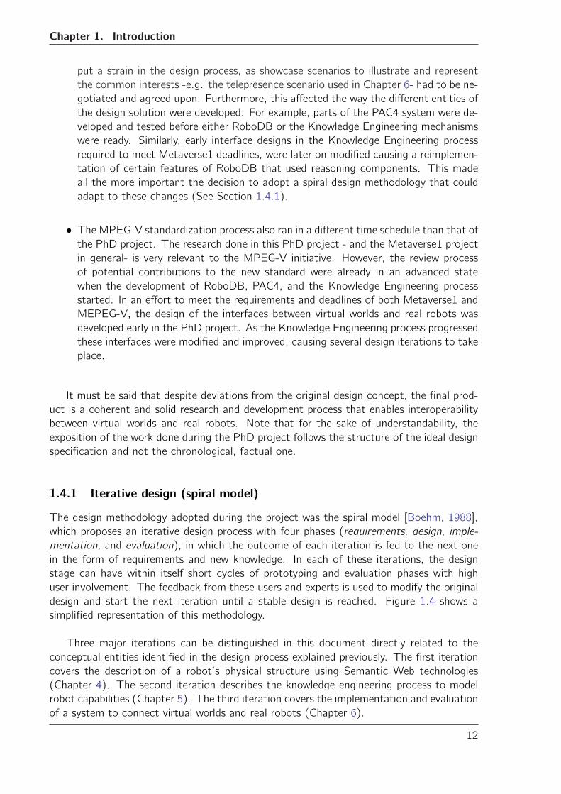
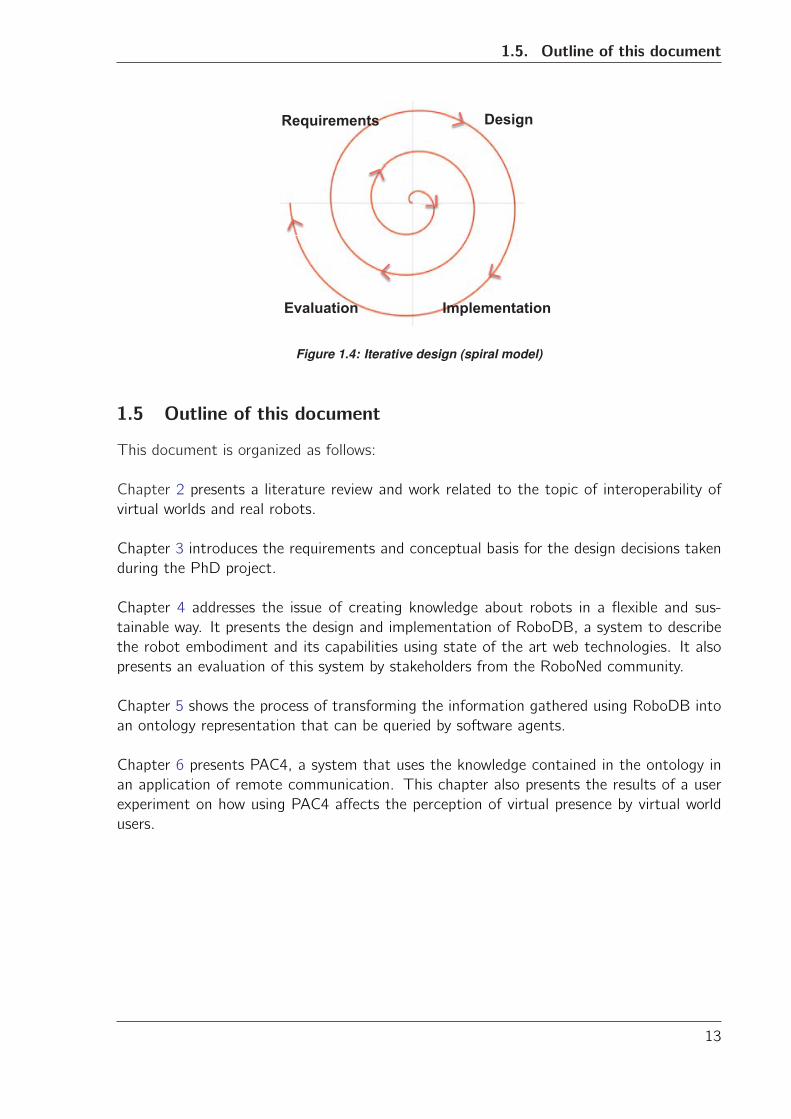
1.4.1 Iterative design (spiral model)
The design methodology adopted during the project was the spiral model [Boehm, 1988],
which proposes an iterative design process with four phases (requirements, design, imple-
mentation, and evaluation), in which the outcome of each iteration is fed to the next one
in the form of requirements and new knowledge. In each of these iterations, the design
stage can have within itself short cycles of prototyping and evaluation phases with high
user involvement. The feedback from these users and experts is used to modify the original
design and start the next iteration until a stable design is reached. Figure 1.4 shows a
simplified representation of this methodology.
Three major iterations can be distinguished in this document directly related to the
conceptual entities identified in the design process explained previously. The first iteration
covers the description of a robot’s physical structure using Semantic Web technologies
(Chapter 4). The second iteration describes the knowledge engineering process to model
robot capabilities (Chapter 5). The third iteration covers the implementation and evaluation
of a system to connect virtual worlds and real robots (Chapter 6).
12
1.5. Outline of this document
Requirements Design
Implementation Evaluation
Figure 1.4: Iterative design (spiral model)
1.5 Outline of this document
This document is organized as follows:
Chapter 2 presents a literature review and work related to the topic of interoperability of
virtual worlds and real robots.
Chapter 3 introduces the requirements and conceptual basis for the design decisions taken
during the PhD project.
Chapter 4 addresses the issue of creating knowledge about robots in a flexible and sus-
tainable way. It presents the design and implementation of RoboDB, a system to describe
the robot embodiment and its capabilities using state of the art web technologies. It also
presents an evaluation of this system by stakeholders from the RoboNed community.
Chapter 5 shows the process of transforming the information gathered using RoboDB into
an ontology representation that can be queried by software agents.
Chapter 6 presents PAC4, a system that uses the knowledge contained in the ontology in
an application of remote communication. This chapter also presents the results of a user
experiment on how using PAC4 affects the perception of virtual presence by virtual world
users.
13

Chapter
2Related work
Since their inception, virtual reality and associated technologies like 3D modelling and gam-
ing brought up the promise of changing the way we relate to each other while working,
learning, or simply enjoying our free time. Albeit perhaps in a different way than originally
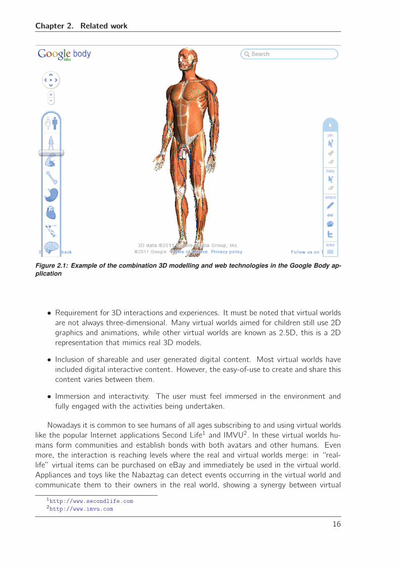
presented, we can see today that the change is starting to happen. For example, Google
Inc. has developed a new product called Google Body [Google, 2011], an application based
on web technologies that presents a detailed 3D model of the human body where the user
can “peel” layers off to reveal different anatomical layers. Furthermore, you can share dis-
coveries by just copying and pasting an URL that points to the exact view of the model that
is currently shown, making sharing “virtual goods” feasible (See Figure 2.1 for a snapshot
of the Google Body application).
As it was presented in Chapter 1 virtual worlds combine several technologies like 3D
modelling and rendering and physics simulation. They also use existing Web infrastruc-
ture like XML, TCP/IP and UDP to communicate and operate. Virtual worlds use these
technologies to create open-ended environments where communities develop and interact.
However, according to De Freitas ([De Freitas, 2008]), there are some characteristics of
current virtual worlds that are essential to be considered as such:
• Shared space and immediacy. Virtual world users want to execute actions and receivefeedback in “real time”. They want to connect to the virtual world and see and share
experiences with others in the same (virtual) space and time.
• Collaboration and persistence. Being alone in a virtual world is not “fun”. As shownin the study by Qian and Feijs [Qian and Feijs, 2004], the fun factor is crucial to
engage people and turn activities commonly labelled as tedious and boring into enter-
taining and appealing. Engagement, collaboration, and the establishment of lasting
relationships are important components for the success of any virtual world.
15
Chapter 2. Related work
Figure 2.1: Example of the combination 3D modelling and web technologies in the Google Body ap-plication
• Requirement for 3D interactions and experiences. It must be noted that virtual worldsare not always three-dimensional. Many virtual worlds aimed for children still use 2D
graphics and animations, while other virtual worlds are known as 2.5D, this is a 2D
representation that mimics real 3D models.
• Inclusion of shareable and user generated digital content. Most virtual worlds haveincluded digital interactive content. However, the easy-of-use to create and share this
content varies between them.
• Immersion and interactivity. The user must feel immersed in the environment andfully engaged with the activities being undertaken.
Nowadays it is common to see humans of all ages subscribing to and using virtual worlds
like the popular Internet applications Second Life1 and IMVU2. In these virtual worlds hu-
mans form communities and establish bonds with both avatars and other humans. Even
more, the interaction is reaching levels where the real and virtual worlds merge: in “real-
life” virtual items can be purchased on eBay and immediately be used in the virtual world.
Appliances and toys like the Nabaztag can detect events occurring in the virtual world and
communicate them to their owners in the real world, showing a synergy between virtual
1http://www.secondlife.com2http://www.imvu.com
16
2.1. Bridging virtual and real worlds
agents and real devices that invites to think that virtual worlds are soon to become part of
everyday life.
2.1 Bridging virtual and real worlds
The connection between virtual and real worlds is a characteristic that has been inherent
to them since the origins of virtual worlds. After all, even those virtual worlds that are
based on the most extreme fantasy contain interactions, rules and concepts that somehow
resemble the ones from real life. However, the bridge between virtual and real can take
many forms -some subtler than others- based on the type of application and interaction
they are designed for. The following sections review the efforts of different stakeholders
(researchers, gamers, etc.) to combine virtual and real.
2.1.1 Virtualized reality
Virtualized reality refers to an immersive visual medium where the virtual model is automat-
ically constructed from images of the real world, preserving the visible detail of real-world
images [Kanade et al., 1997]. A virtualized reality process usually involves three phases:
capturing a visual event (usually through a complex array of camera sensors), recovering
the 3D structure from that event, and generating different user viewpoints. Some of the
challenges originally faced by this processes were the calculation of depth from multiple
camera images, the image flow and pixel correspondence in the scene view synthesis, and
the calculation of (arbitrary) viewing positions for the scene.
Virtualized reality was an effort to improve virtual reality by adding the fine detail of
the real world, especially in the early days when virtual worlds were created using simplistic,
approximated CAD models [Kanade et al., 1995]. The techniques used had a strong impact
in the area of entertainment, where techniques for 3D video capture [Wurmlin et al., 2002],
character animation [Starck et al., 2005] and scene reconstruction were developed.
It must be mentioned that the advances in the level of realism achieved by modern 3D
modelling and rendering techniques, as well as the constant evolution and improvement in
computer graphics and processing power of modern virtual reality systems have rendered
virtualized reality almost obsolete.
2.1.2 Mixed reality
Milgram and Kishino ([Milgram and Kishino, 1994]) define mixed reality as those virtual
reality related techniques that involve merging virtual and real worlds, and that fall some-
where along the virtuality continuum (the spectrum of applications between real and virtual
worlds). In other words, in a mixed reality setting virtual and real objects co-exist and are
displayed next to each other in a seamless, effortless way. Figure 2.2 shows the virtuality
continuum and some of its components.
Mixed reality environments can be further classified into augmented reality (AR) and
augmented virtuality (AV). Augmented reality is a variation of virtual reality that allows the
17
Chapter 2. Related work
Figure 2.2: Representation of the virtuality continuum as appeared in [Milgram and Kishino, 1994]
user to see the real world with virtual objects superimposed upon or composed with the real
world. Augmented reality supplements reality rather than completely replacing it [Azuma
et al., 1997].
An important characteristic of augmented reality is that it is interactive in real time.
This means that input from the user through sensors or specialized user interfaces (e.g. head
mounted displays, mobile phones, tablet PCs, etc.) are a requirement for systems to be
considered AR. Examples of application areas are medical training, manufacturing and re-
pair, and annotation and visualization of objects.
Augmented virtuality enhances or augments the virtual environment with data from the
real world. An example of this kind of systems is the Cibercity Walker described in [Tamura
et al., 2001], where the user can walk through a virtual world created from a database of
video images captured by systematically driving a real car with video cameras and various
sensors attached. The users can control the speed of the motion to experience the city as a
walker or as a car racer, and select where to go in the city. The Cibercity Walker utilizes the
sensor information available to create a more realistic experience for the user. Figure 2.3
shows a user navigating through the augmented virtuality system using a joystick to control
the movement of the virtual camera.
Figure 2.3: The CibercityWalker augmented virtuality system.
18
2.2. Cross-reality
It can be said that virtualized reality (Section 2.1.1) was a precursor, more focused
version of augmented virtuality systems, as it used real-world images to improve the virtual
models (and user experience) in the virtual world. The main difference between both is the
extent (and intent) of the use of real-world imagery to augment the virtual world: virtualized
reality tries to achieve maximum accuracy and resemblance in the virtual representation of
reality, while augmented virtuality serves a more general purpose of providing support to
the virtual environment with real-world data. Nevertheless, the line that separates them is
indeed fine and blurry at times.
2.2 Cross-reality
Cross-reality is a type of augmented virtuality that deals specifically with mixing ubiquitously
networked sensor/actuator infrastructure and online virtual worlds like the immersive game
World of Warcraft, and the general-purpose world of Second Life [Paradiso and Landay,
2009].
While incorporating sensor input is not necessarily a requirement for augmented vir-
tuality, the key element of cross-reality settings is the presence of sensors and actuators
as the bridge to the real world, bringing the real into the virtual. For example, Want et
al. ([Want et al., 1999]) explored the design and implementation of physical devices that
incorporated RFID technology to create a new user experience with everyday objects and
their affordances. These tags provide an ID that can be assigned to real objects so that
detecting the tag with an RFID reader will trigger an event in the virtual world. An example
application is the inclusion of RFID tags in real books in such a way that “touching” the
real book with a tablet computer would trigger a search in a virtual library and display the
digital version of the document.
The same principle was applied by Sims [Sims, 1994] to model virtual sensors and actua-
tors and combine them with real ones. Real sensors (joint angle, contact and photo-sensors)
are used in a physical simulation to calculate movement of virtual creatures in virtual three-
dimensional worlds. This simulation was able to create complex behaviours like swimming,
walking and jumping. These behaviours could, in principle, be used to create real devices
that imitate the virtual ones.
Cross-reality’s fundamental concept is akin to that of the Internet of things: a world
where a variety of things or objects are able to sense and interact with each other and co-
operate with their neighbouring “smart” components to reach common goals [Giusto et al.,
2010]. Cross-reality incorporates 3D virtual worlds as the smart component by excellence, a
complex, dynamic, and evolving system where virtual agents controlled by humans interact
with ubiquitous virtual and real objects in a seamless way.
2.3 Cross-reality and robotics
Communication networks connecting virtual and real devices allow them to share informa-
tion. This can save time and money, and boost the overall capabilities of the system as a
19
Chapter 2. Related work
whole. An example is the experience of robot manufacturer ABB with a series of always-on
industrial robots capable of automatically reporting equipment faults and trigger a main-
tenance process. Before this capability was present, customers would have to wait for a
service engineer to fix the problem in person. With this networked system, ABB robots can
avoid more than 60% of production stoppages [Conti, 2006, ABB, 2008].
Integration of robotic devices into cross-reality has already started. Massie and Salis-
bury ([Massie and Salisbury, 1994]) designed and built a haptic interface that measures the
user’s fingertip position and produces a control vector on the fingertip. This information is
used to manipulate virtual objects and evaluate the user perception of how those objects
“feel”. The ideal application of this technology is on the design and control of remote
robotic manipulators.
Another example is the teleoperation and underwater navigation training developed by
Lin et al. ([Lin and Kuo, 2001]). A teleoperated underwater robot was positioned in a
deep-water tank along with a simplified model of an oil platform. The robot was coupled to
a virtual reality environment with a virtual model of the oil platform and surrounding marine
environment. The robot sensor data was used to improve the accuracy of the navigation
through the virtual model during pilot training sessions and teleoperation missions.
These and other examples seem to indicate that the integration of robots into cross-
reality has already been achieved. A closer look, however, reveals that true interoperability
between these two domains is not yet a reality.
Although traditionally virtual environments have had strong, real-time input and out-
put requirements with closed, proprietary knowledge representations, cross-reality systems
are slowly starting to change this as they approach interoperability from the perspective
of the Internet of things. As such, the different software frameworks that connect vir-
tual and real devices have a web-oriented architecture. Not only they use existing Web
protocols and standards as transport medium, but they can also use HTTP as an applica-
tion layer, exposing representational state transfer (RESTful) APIs for direct access and
in general, modelling systems from the perspective of web services [Boman, 1995, Stirbu,
2008, Guinard et al., 2009].
In the case of robots, the robotics community has also struggled to achieve interoper-
ability. This has been an ongoing topic of discussion especially among researchers focusing
on the development of robotic middleware. The definition of middleware is a “class of soft-
ware technologies designed to help manage the complexity and heterogeneity inherent in
distributed systems” (Bakken, D. [Bakken, 2002]). Most robots are designed as distributed
systems, therefore, robotic middleware must find a way to appropriately describe heteroge-
neous embodiments and make (remote) robotic control software, and robotic telepresence
interfaces much more reusable and manageable.
Several middleware platforms have been developed in the last decades with varying
degrees of success. An example is the Player system [Gerkey et al., 2001]. Player is a mid-
dleware software platform that works as a network server interface to a collection of sensors
and actuators that typically constitute a robot. Player exhibits a client-server architecture.
20
2.3. Cross-reality and robotics
The Player server implements an asynchronous multi-threaded model to communicate
with physical devices in the robot. This means that the server creates one thread for each
sensor and actuator accessible through the player interface. Each thread establishes a TCP
socket connection to exchange information with a client program.
Player clients are programs that can reside either in the same physical computer as the
server, or in a remote computer. They usually contain the logic and code necessary to
process the sensor information provided by the Player server and issue commands to be
interpreted and executed by it. Figure 2.4 shows the Player architecture as appeared in the
paper from Gerkey et al. [Gerkey et al., 2001].
Figure 2.4: Player system architecture as appeared in [Gerkey et al., 2001]
Clients that try to access the robot devices and capabilities must invoke the Player Ab-
stract Device Interface (PADI), a custom abstraction that defines the syntax and semantics
of the data that is exchanged between the control code in the clients and the Player server.
PADI is specified as a set of C message structures. More recent versions of Player allow re-
placing the TCP/IP based communication with CORBA protocols, and even defining a new
PADI using an Interface Definition Language (IDL) [Vaughan and Gerkey, 2007]. Similar
approaches to define a robot and its capabilities are used by other middleware like Miro [Utz
et al., 2002], XPERSIF [Awaad et al., 2008] or Robot Operating System (ROS) [Quigley
21
Chapter 2. Related work
et al., 2009]. Some of them even go as far as offering distributed network control capabil-
ities that allow robots and other devices to communicate and interact among themselves.
However, most robotic middleware fails when trying to integrate robots into the Web and
the Internet of things, mostly due to two key problems:
• Syntactic interoperability. The data formats and protocols of most robotic middlewareare engineered around data structures that robots have traditionally used and under-
stood, i.e. object-based representations that allow for specialized forms of remote
procedure calls and information exchange. This is evident in the previous example
of Player middleware: although Player utilizes a data transport infrastructure that is
compatible with that of the Web, the communication protocol has been especially
designed to run under specific constraints. Some of these constraints, like sending
data packages at 10Hz frequency (30Hz for vision) and the custom definition and
implementation of C structures in PADI, are not compatible with common Web stan-
dards. Few middleware platforms offer RESTful APIs, simple object access protocol
(SOAP) interfaces, or compliance with commonly used web formats for information
exchange and web service definition like WSDL or UDDI [Blake et al., 2011, Remy
and Blake, 2011]. Even basic elements like web interfaces for remote control are
sometimes missing from middleware packages.
• Knowledge representation. The knowledge about robots and their capabilities ismostly implicit in the software that controls the robot. The discovery and use of
this knowledge becomes difficult without the appropriate knowledge representation to
make use of it. In other words, integrating a robot into cross-reality is only possible
if a the robot can not only connect to the network, but also answer questions from
other virtual and real agents about what it can do. Unfortunately, current middleware
platforms offer few or no alternatives to achieve this.
Addressing these factors raises many questions like what are the appropriate technologies
to represent this kind of knowledge about robots in a way that is “open” to the Web? How
can this knowledge be created, maintained, and exploited in a sustainable way? What kind
of data format and interfaces must be developed to achieve syntactic interoperability while
at the same time using the knowledge available about the robot capabilities?
2.4 Creating knowledge about robots
Traditionally, robotics has approached the problem of describing a robot and its capabilities
from the perspective of action selection and planning. A good knowledge representation of
the robot’s characteristics and abilities is essential to enable the creation of complex and
dynamic plans for action execution in diverse areas like navigation or manipulation.
Research on robot task planning and execution has led to several theories for repre-
senting the robot embodiment and capabilities. Tang and Parker [Tang and Parker, 2007]
describe robot capabilities as schemas with inputs and outputs labelled according to the type
of information they convey. These labels are used when matching the task requirements
with the robot capabilities to create a plan for task execution.
22
2.4. Creating knowledge about robots
Montesano et al. [Montesano et al., 2008] relate the robot capabilities to affordances.
In this context, capabilities are the actions that the robot can execute and the effects of
these actions. In this approach, the knowledge representation is given by a probabilistic
direct graphical model representing the different actions the robot can execute and the
perceived effects. This theoretical foundation is also at the heart of the approach presented
by Shiroma et al. [Shiroma and Campos, 2009]. In this approach, capabilities are consid-
ered as actions with inputs and outputs that are independent from the robot embodiment.
Furthermore, an action is a module that can produce data, consume data, or achieve a
task. Providing varying levels of abstraction in its implementation.
In recent years there have also been some attempts to address the problem of knowl-
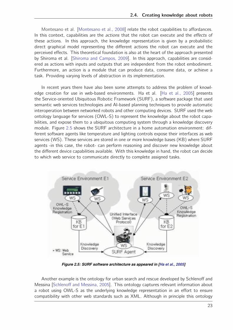
edge creation for use in web-based environments. Ha et al. [Ha et al., 2005] presents
the Service-oriented Ubiquitous Robotic Framework (SURF), a software package that used
semantic web services technologies and AI-based planning techniques to provide automatic
interoperation between networked robots and other computing devices. SURF used the web
ontology language for services (OWL-S) to represent the knowledge about the robot capa-
bilities, and expose them to a ubiquitous computing system through a knowledge discovery
module. Figure 2.5 shows the SURF architecture in a home automation environment: dif-
ferent software agents like temperature and lighting controls expose their interfaces as web
services (WS). These services are stored in one or more knowledge bases (KB) where SURF
agents -in this case, the robot- can perform reasoning and discover new knowledge about
the different device capabilities available. With this knowledge in hand, the robot can decide
to which web service to communicate directly to complete assigned tasks.
Figure 2.5: SURF software architecture as appeared in [Ha et al., 2005]
Another example is the ontology for urban search and rescue developed by Schlenoff and
Messina [Schlenoff and Messina, 2005]. This ontology captures relevant information about
a robot using OWL-S as the underlying knowledge representation in an effort to ensure
compatibility with other web standards such as XML. Although in principle this ontology
23
Chapter 2. Related work
exposed the robot capabilities to other software agents, in practice no service registration
and discovery module was implemented and therefore the ontology could be used only by
knowledge engineering applications like Protege [Knublauch et al., 2004]. The goal of this
ontology was to assist in the development, testing and certification of effective robotics
technologies for sensing, mobility, navigation, and planning within the search and rescue
domain.
These approaches share some fundamental concepts with the planning community.
Robot capabilities are described on terms of input, outputs, preconditions and effects,
regardless of the actual implementation. There are forms of registration and discovery
of these capabilities (i.e. services) so that they can be used by external software agents
e.g. planners, web software agents, etc. Robots are seen as providers of services rather
than monolithic entities.
From the state of the art, it can be concluded that there is a clear tendency on the kind
of technologies used to make information about robots available to the web, with service-
oriented system architectures and Semantic Web technologies and tools seemingly ideal for
this application.
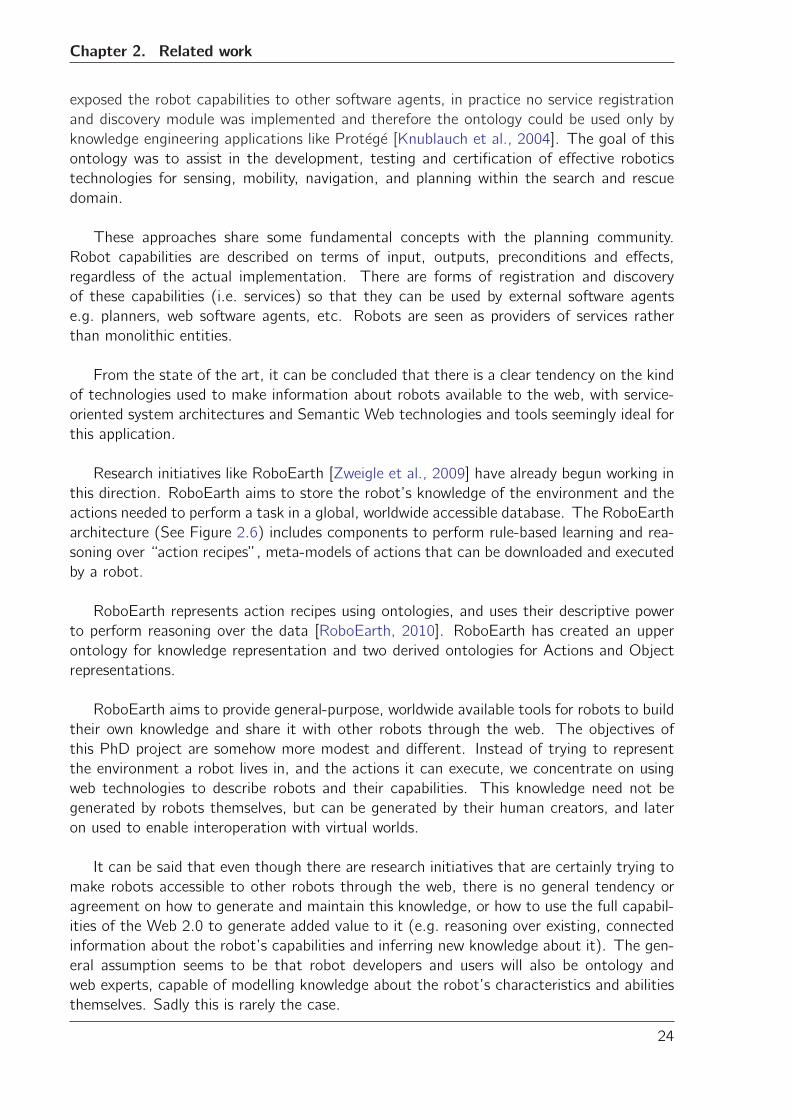
Research initiatives like RoboEarth [Zweigle et al., 2009] have already begun working in
this direction. RoboEarth aims to store the robot’s knowledge of the environment and the
actions needed to perform a task in a global, worldwide accessible database. The RoboEarth
architecture (See Figure 2.6) includes components to perform rule-based learning and rea-
soning over “action recipes”, meta-models of actions that can be downloaded and executed
by a robot.
RoboEarth represents action recipes using ontologies, and uses their descriptive power
to perform reasoning over the data [RoboEarth, 2010]. RoboEarth has created an upper
ontology for knowledge representation and two derived ontologies for Actions and Object
representations.
RoboEarth aims to provide general-purpose, worldwide available tools for robots to build
their own knowledge and share it with other robots through the web. The objectives of
this PhD project are somehow more modest and different. Instead of trying to represent
the environment a robot lives in, and the actions it can execute, we concentrate on using
web technologies to describe robots and their capabilities. This knowledge need not be
generated by robots themselves, but can be generated by their human creators, and later
on used to enable interoperation with virtual worlds.
It can be said that even though there are research initiatives that are certainly trying to
make robots accessible to other robots through the web, there is no general tendency or
agreement on how to generate and maintain this knowledge, or how to use the full capabil-
ities of the Web 2.0 to generate added value to it (e.g. reasoning over existing, connected
information about the robot’s capabilities and inferring new knowledge about it). The gen-
eral assumption seems to be that robot developers and users will also be ontology and
web experts, capable of modelling knowledge about the robot’s characteristics and abilities
themselves. Sadly this is rarely the case.
24
2.4. Creating knowledge about robots
Figure 2.6: RoboEarth robot architecture as appeared in [Zweigle et al., 2009]
Furthermore, the general impression is that although the importance of interoperability
between web-connected systems has long been recognized, work on connecting robots to
the Web offering their services to other heterogeneous web agents, is limited and isolated.
In the case of interoperability with virtual worlds, this is virtually non-existent.
25

Chapter
3Requirements and concepts
In Chapter 1 we outlined the focus of this technological design on three aspects: mak-
ing knowledge about the characteristics and abilities of robots available to heterogeneous
web agents, the creation and maintenance of such knowledge, and the virtual world user
experience with a system enhanced by that knowledge. These three aspects are explored,
implemented, and evaluated in two systems developed during the PhD project. The gener-
ation of knowledge about the characteristics of a robot, and how to make this knowledge
available on the Web are covered in the RoboDB knowledge acquisition system. The use
of this knowledge to connect virtual worlds and real robots, and the effect this has in the
virtual world user experience is covered by the PAC4 service registration system. In this
chapter we briefly introduce both systems and their initial requirements, while a more de-
tailed account of their design and implementation is presented in Chapters 4 to 6.
Given the iterative design and development methodology chosen for this project, it
was not feasible to produce beforehand an exhaustive list of qualitative and quantitative
requirements for all future systems that could be developed to tackle the issues mentioned
above. Instead, the requirements are summarized in this chapter as the initial heuristics,
explorations, and design considerations and principles of the different application scenarios
chosen for this project.
3.1 RoboDB
RoboDB stands for Robot DataBase, and is a web system that gathers information about
the robot’s physical characteristics and abilities in an interactive way. During the develop-
ment of RoboDB the focus was on investigating the different web technologies that could
be used to describe a robot, and on making this information available on the web not only to
human users, but also to (automated) software agents. The goal of RoboDB was to build an
27
Chapter 3. Requirements and concepts
interactive platform where the intended users of the system (primarily robotics researchers,
developers and users, but also virtual world and web users as well as semi-automated soft-
ware systems) could access and contribute information about robotic devices, maintain this
information and reuse it in content creation and other applications.
3.1.1 Functional requirements for RoboDB
The functional requirements can be grouped in several categories: information access, sys-
tem flexibility, collaboration and sustainability.
RoboDB is intended as a web application usable by human and well as machine users.
This is emphasized by the fact that this information will be later on used to interoperate
with virtual worlds, which are for all practical effects web agents. Therefore, various inter-
faces must be available for human-machine and machine-machine interactions. Access to
the information should have essentially two modes: web browser and web-service endpoint.
Web browser access mode additional requirements
In this mode the information is presented in a human-friendly way through a web browser
application. Usability of the web interfaces will be measured with respect to the easiness
with which the user can store and retrieve information from the system
Facilitating knowledge creation is an important factor to consider in this system. It
cannot be expected that every robot user, developer, and researcher is an expert in knowl-
edge extraction and modelling, ready to use this expertise to describe the characteristics
and capabilities of a robot. Therefore, RoboDB should guide the user during the process of
creating knowledge about robots. Furthermore, an attractive feature of robotic hardware
is the facility to modify it by adding or eliminating components. Therefore, RoboDB must
be flexible enough to cope with the high reconfigurability of robotic systems, while keep-
ing the process of creating and modifying robot descriptions accessible to the system’s users.
Another key requirement of this system is collaboration. It is hardly possible that a
single person or even a small group of people can gather information about all available
robotic devices. Therefore, RoboDB should enable collaboration and discussion between
the different user communities. The system’s users themselves should be in charge of
contributing and maintaining the information in it. This requirement has a considerable
impact on the design of the system. Given the current rate of development of robots, it
is important to make information available with the smallest latency using easy to learn
tools in a community-oriented environment. This would also allow the self-maintenance of
content, as well as promoting virtually everyone to have a say with respect to the knowledge
produced by the system, encouraging communication, discussion, and collaboration.
Web-service endpoint access mode additional requirements
Using this access modality semi-automated agents can perform low-level queries in one
or more query languages to the information and knowledge of the system. This access
mechanism must provide a syntax that is easy to learn and remember. The response ob-
28
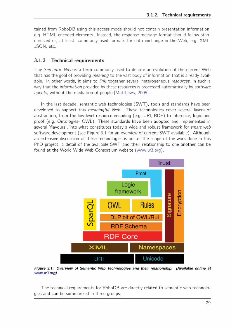
3.1.2. Technical requirements
tained from RoboDB using this access mode should not contain presentation information,
e.g. HTML encoded elements. Instead, the response message format should follow stan-
dardized or, at least, commonly used formats for data exchange in the Web, e.g. XML,
JSON, etc.
3.1.2 Technical requirements
The Semantic Web is a term commonly used to denote an evolution of the current Web
that has the goal of providing meaning to the vast body of information that is already avail-
able. In other words, it aims to link together several heterogeneous resources, in such a
way that the information provided by these resources is processed automatically by software
agents, without the mediation of people [Matthews, 2005].
In the last decade, semantic web technologies (SWT), tools and standards have been
developed to support this meaningful Web. These technologies cover several layers of
abstraction, from the low-level resource encoding (e.g. URI, RDF) to inference, logic and
proof (e.g. Ontologies- OWL). These standards have been adopted and implemented in
several ‘flavours’, into what constitutes today a wide and robust framework for smart web
software development (see Figure 3.1 for an overview of current SWT available). Although
an extensive discussion of these technologies is out of the scope of the work done in this
PhD project, a detail of the available SWT and their relationship to one another can be
found at the World Wide Web Consortium website (www.w3.org).
Figure 3.1: Overview of Semantic Web Technologies and their relationship. (Available online atwww.w3.org)
The technical requirements for RoboDB are directly related to semantic web technolo-
gies and can be summarized in three groups:
29
Chapter 3. Requirements and concepts
• Reusability and Availability. The technologies used in RoboDB should be state-of-the-art, but at the same time be easily available. The reason for this is that popular
software and technologies are more likely to be actively maintained either commer-
cially or by a community of users. An example of this is Topic Maps, a standard for
the representation and exchange of knowledge with emphasis in information findability
[Biezunski et al., 2001]. Despite it providing a semantic abstraction and expressivity
similar to that of OWL, the latter has been preferred and considerably more devel-
oped by the semantic community. Additionally, the final result of this PhD project is
intended to be freely available to other researchers and users that would like to con-
tinue with further development. Therefore, open source technologies with a proven
community of users and developers are preferred over more closed or seldom used
(commercial) solutions.
• Knowledge creation. A key aspect of this project is the need to generate knowledgeabout robots and their capabilities. Not all semantic web technologies are capable
of doing that. For example, while keyword tagging may help in organizing and struc-
turing textual content in websites, it usually does not provide sufficient means to
obtain implicit knowledge from those tags. A knowledge representation that favours
automated reasoning will be preferred.
• Web-friendliness. The technologies and tools chosen for knowledge extraction, access,and presentation should be based on web standards whenever possible. For example,
the Protege knowledge extraction tool [Gennari et al., 2003] is one of the most
popular tools for knowledge extraction from semantic data. However, its integration
with other available web technologies is not straightforward. Technologies that offer
a readily available web access and easy integration with popular web development
technologies will be preferred.
3.2 PAC4
The Prototype for Assisted Communication (PAC4) is a system that connects virtual worlds
to real sensors and actuators, allowing the harvesting of information and different forms of
device control. PAC4 was developed in the context of the Metaverse1 European project
briefly introduced in Chapter 1.
The Metaverse1 project1 was a cooperation between academia and industry funded by
the Information Technology for European Advancement programme (ITEA2) to investi-
gate the creation of global standards among real and virtual worlds. The objective of the
Metaverse1 project was to provide a standardized global framework that enabled the inter-
operability between virtual worlds such as Second Life, World of Warcraft, and Google Earth
among others, and real world sensors, actuators, vision and rendering, social and welfare
systems, banking, etc.
Metaverse1 aimed to characterize the business dynamics, the user behaviour, and the
technology standards needed to construct a framework where services could be created,
deployed, and exploited profitably and sustainably. This involved defining ontologies and
1http://www.metaverse1.org/
30
3.2.1. Functional requirements
tools that permit to describe, search, and make content available in every virtual and real
context, as well as investigating appropriate system architectures and data exchange pro-
tocols that allow content discovery, invocation, and exchange.
The project consortium consisted of over 40 partners from industry and academia, dis-
tributed across 7 countries in Europe. Examples of partners are Philips2, Alcatel-Lucent3,
Vrije-Universiteit Brussel4, and TU Eindhoven. During the development of PAC4, there
was a close collaboration with consortium partners DevLab. The contribution of this PhD
project to PAC4 was the core service registration software based on the observer pattern.
DevLab and VU Amsterdam contributed the technical infrastructure such as web servers,
virtual world setup, and wireless sensor network. Detailed information on the software de-
sign and implementation will be provided in Chapter 6.
The objective of PAC4 was to showcase the research done on interoperability in a
scenario of remote (assisted) communication. In this scenario virtual world users receive
information about a remote peer from a wireless sensor network and a robot companion
within the virtual world. At the same time, they can interact with the remote peer using
the real robot as proxy. All this is done from within the virtual world.
3.2.1 Functional requirements
The functional requirements of PAC4 are related to the virtual world user experience while
interacting with a virtual world that has been enhanced with the sensor and actuator infor-
mation in the scenario outlined above:
• Information processing and presentation. PAC4 should integrate seamlessly with thevirtual world in such a way that the virtual world use can use the additional features
and information produced by real world sensors and actuators. PAC4 must process
and display information from the real devices within the virtual world in an unobtrusive,
yet useful way. Control of the remote robotic device should be possible through a
virtual interface, preferably in-world.
• User experience. The virtual world enhanced with the robot and sensor networkcapabilities should make an impact in the feeling of presence in the remote location.
A virtual world user should experience an increased sense of “being there” while
communicating with a person in a remote location.
3.2.2 Technical requirements
The communication and interaction capabilities of the virtual worlds selected to showcase
the different scenarios in Metaverse1 provided already some technical requirements that
PAC4 should fulfil:
• REST compatible communication. The trend in communication frameworks observedin popular virtual worlds like Second Life and BlueMars points toward Representational
2http://www.philips.com/3http://www.alcatel-lucent.com/4http://www.http://smit.vub.ac.be/
31
Chapter 3. Requirements and concepts
State Transfer (REST) APIs to access the different services available. REST is a set
of architectural constraints that provide data, connection, and processing elements to
govern the interaction between web resources [Fielding and Taylor, 2002]. Common
operations in REST are GET, POST, DELETE and UPDATE. An implementation
that supports all these operations is known as RESTful. PAC4 should use a REST-
style client-server architecture to manage the interaction with virtual worlds.
• Service oriented architecture. In distributed networks it is a general trend to repre-sent devices capabilities as services. Web services are good at handling knowledge
representations described in different languages like XML, WSDL, or RDF. It makes
sense then, to use service-oriented architecture principles to support the interaction
with the different virtual and real agents and devices. This would also allow easier
access to other sources of information provided as web-services (e.g. RoboDB).
• Reusability and availability. Similar to RoboDB, open source, popular and open tech-nologies are preferred for the development of PAC4. For example, the selection of
the virtual world to use as a demonstrator should favour stable graphics and tools as
well as open source platforms over cutting-edge, isolated ones.
This chapter presented the initial requirements of two systems developed during the
project. These requirements also outlined the general guiding principles followed during
the development of this PhD project. In an informal and simplified way, these principles
can be expressed as “do not reinvent the wheel” and “remember that the users of these
systems are multidisciplinary”. These principles are palpable in both the technical and
functional requirements presented above. In the following chapters we will describe in
detail the development of both systems, and how they complement each other, enabling
interoperability between virtual worlds and real robots.
32
Chapter
4From data to information: RoboDB
RoboDB is a web-based system that helps the human user to create descriptions of robotic
devices and their capabilities. This knowledge can be used by other (web) agents and sys-
tems in different applications, for example, to figure out what kind of language a robot can
“speak”, or what type of sensors and actuators can be used from within a virtual world.
In Chapter 3 we presented the initial requirements for RoboDB. The aim was to integrate
in RoboDB the right technologies and tools that allowed to properly describe robots and
make this information available to human users and also to virtual worlds, while keeping
the complexity of this process to an acceptable level. As we mentioned in Chapter 1,
the design and implementation of this system followed the spiral design methodology with
several iterations. In the following sections we present the initial design and implementation
of the system and the subsequent development cycles.
4.1 Data format selection
The first iteration in the development process of RoboDB was to choose the appropriate
data format to encode knowledge about robots. Three web data formats for information
exchange were compared: Extensible Markup Language (XML), Resource Description For-
mat (RDF) and its dialect Web Ontology Language (OWL), and Topic Maps.
XML [Bray et al., 2000] is a text format originally designed for large-scale electronic
publishing. The goal of XML was to create a generic format to be served, received, and
processed on the Web. A key feature of XML is flexibility : the vocabulary of tags and their
allowed combinations is not fixed and can be defined on a per-application basis [Decker
et al., 2000]. While this flexibility is well appreciated while encoding generic and complex
information like robot descriptions, successful data exchange requires a set of basic rules
33
Chapter 4. From data to information: RoboDB
that allow different systems to understand and agree on the vocabulary that is being used
in a particular XML file. XML Schema [Sperberg-McQueen and Thompson, ] is a doc-
ument containing the set of rules to describe the structure of a given XML document.
XML Schemas not only define the legal building blocks of an XML file, but also define
datatypes, restrictions and validation over the encoded data. The final piece in the XML
puzzle required to distribute information in a scalable and successful way are the Extensible
Stylesheet Language Transformations (XSLT) [Clark et al., 1999]. XSLT allow to trans-
form one XML document into another, with the possibility of manipulating the input XML
tree by adding or removing elements in the output tree.
To encode the information about robots using XML, there is a need to also create an
XML Schema file that defines the different tags, datatypes, and basic rules for exchange
of information. One or more XSLT would also need to be in place to convert XML docu-
ments into other alternative schemas (e.g. Scalable Vector Graphics (SVG) for images of
the robot structure). The biggest disadvantage of this representation is that neither an
XML Schema nor an XSLT says anything about the meaning of the information encoded,
potentially resulting in ambiguity of the vocabulary used. Furthermore, combining different
XML trees is a non-trivial task that usually requires the development of ad-hoc software
[Fontaine, 2002]. Listing 4.1 shows an example of a possible xml encoding of a simple robot.
<? xml v e r s i o n=” 1 .0 ” encod i ng=”UTF−8” ?>
<r obo t name=”TestRobot ”>
<component i d=”comp1” t ype=” a c t u a t o r ”>Mob i l e base</component>
<component i d=”comp2” t ype=” s e n s o r ”>U l t r a s o u nd</component>
</ robo t>
Listing 4.1: Example of XML data encoding
RDF [RDF, 2004] is a model for data interchange on the web developed by the World
Wide Web Consortium (W3C). Although RDF is only a recommendation by W3C, in prac-
tice it has become the de-facto standard for web knowledge representation. RDF encodes
data in triples, a construction of the form subject-predicate-object. The main difference
between RDF and XML is that RDF is in itself a model to describe qualified (named)
relationships between web resources. The same model can be used as new knowledge is
encountered, without the need of redefining it. This is also an advantage of RDF over
XML: it defines the “language” for information exchange with well understood rules and
internal semantics implicitly encoding “meaning” in the form of relationships. Redefinition
and/or modification of these relationships and their meaning does not require a modification
of the underlying schema for information exchange, i.e. the RDF model stays the same.
Listing 4.2 shows an example RDF encoding of a simple robot.
<? xml v e r s i o n=” 1 .0 ” encod i ng=”UTF−8” ?>
<rd f :RDF
xm l n s : r d f=” h t t p : //www. w3 . o rg /1999/02/22− r d f−s yn tax−ns#”xm l n s : r d b=” h t t p : //www. robodb . o rg / o n t o l o g i e s / r obo t#”>
< r d f : D e s c r i p t i o n
r d f : a b o u t=” h t t p : //www. robodb . o rg / o n t o l o g i e s / r obo t /TestRobot ”>
34
4.1. Data format selection
<r db : ha s componen t>Mob i l e base</ rdb : ha s componen t>
<r db : ha s componen t>U l t r a s o u nd</ rdb : ha s componen t>
</ r d f : D e s c r i p t i o n>
</ rdf :RDF>
Listing 4.2: Example of RDF data encoding
RDF Schema (RDF-S) [World Wide Web Consortium (W3C), ] is a specification that
describes how to use RDF to describe RDF vocabularies. It effectively extends RDF to
include domain and range, subclass and subproperty relationships, collections, and reifica-
tion. OWL [OWL, 2004] is a language designed to facilitate machine interpretability of
Web content and effectively extends RDF(-S) by providing additional vocabulary along with
formal semantics. More importantly, OWL introduces the possibility of performing inference
and extracting new knowledge from data encoded using RDF(-S) using inference engines
based on Description Logics (DL). Chapter 5 will present a brief theoretical account of DL
and their use in knowledge engineering.
The disadvantage of encoding knowledge using RDF(-S)/OWL is the loss of flexibility,
as information needs to be appropriately modelled in the form of triples, following the se-
mantic rules dictated by RDF(-S)/OWL. Furthermore, certain constructs that are relatively
easy to model using XML, become fairly complicated using RDF(-S)/OWL, e.g. linked or-
dered lists and trees.
Topic Maps [Topic Maps, 2002] is a technology standard (ISO-IEC 13250) for encod-
ing knowledge and connecting this knowledge to other information sources. The data is
encoded in constructs consisting of subjects (called topics) and relationships (called as-
sociations). A topic map is a collection of these elements. Similar to RDF(-S)/OWL,
topic maps provide an abstract model to define datatypes, supertypes, and instances of
topics. It also allows the encoding of meaning by using the subject-association paradigm.
An advantage over RDF(-S)/OWL is the clear methodology for merging different topics to
avoid redundant and ambiguous constructs. As a disadvantage, Topic Maps do not offer
the possibility of inference and knowledge discovery beyond the type-subtype relationships
and the merge constructs defined in the standard. Furthermore, their use is not widespread
with few real-world applications known, and interoperability between Topic Maps and RDF(-
S)/OWL still incomplete. Listing C shows an example topic map encoding.
<? xml v e r s i o n=” 1 .0 ” encod i ng=”UTF−8” ?><top icMap xmlns=” h t t p : //www. top i cmaps . o rg /xtm /1 .0/ ” xm l n s : x l i n k=” h t t p :
//www. w3 . o rg /1999/ x l i n k ”>
< t o p i c i d=” robo t1 ”>
<baseName>
<baseNameSt r i ng>TestRobot</ baseNameSt r i ng>
</baseName>
</ t o p i c>
< t o p i c i d=”mob i l e−base ”><baseName>
<baseNameSt r i ng>Mob i l e Base</ baseNameSt r i ng>
</baseName>
</ t o p i c>
< t o p i c i d=” u l t r a s o u n d ”>
<baseName>
35
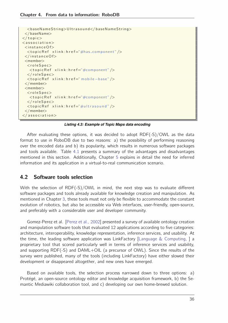
Chapter 4. From data to information: RoboDB
<baseNameSt r i ng>U l t r a s o u nd</ baseNameSt r i ng>
</baseName>
</ t o p i c>
<a s s o c i a t i o n>
< i n s t a n c eO f>
<t o p i c R e f x l i n k : h r e f=”#has component ”/>
</ i n s t a n c eO f>
<member>
< r o l e S p e c>
<t o p i c R e f x l i n k : h r e f=”#component ”/>
</ r o l e S p e c>
<t o p i c R e f x l i n k : h r e f=”mob i l e−base ”/></member>
<member>
< r o l e S p e c>
<t o p i c R e f x l i n k : h r e f=”#component ”/>
</ r o l e S p e c>
<t o p i c R e f x l i n k : h r e f=”#u l t r a s o u n d ”/>
</member>
</ a s s o c i a t i o n>
Listing 4.3: Example of Topic Maps data encoding
After evaluating these options, it was decided to adopt RDF(-S)/OWL as the data
format to use in RoboDB due to two reasons: a) the possibility of performing reasoning
over the encoded data and b) its popularity, which results in numerous software packages
and tools available. Table 4.1 presents a summary of the advantages and disadvantages
mentioned in this section. Additionally, Chapter 5 explains in detail the need for inferred
information and its application in a virtual-to-real communication scenario.
4.2 Software tools selection
With the selection of RDF(-S)/OWL in mind, the next step was to evaluate different
software packages and tools already available for knowledge creation and manipulation. As
mentioned in Chapter 3, these tools must not only be flexible to accommodate the constant
evolution of robotics, but also be accessible via Web interfaces, user-friendly, open-source,
and preferably with a considerable user and developer community.
Gomez-Perez et al. [Perez et al., 2002] presented a survey of available ontology creation
and manipulation software tools that evaluated 12 applications according to five categories:
architecture, interoperability, knowledge representation, inference services, and usability. At
the time, the leading software application was LinkFactory [Language & Computing, ] a
proprietary tool that scored particularly well in terms of inference services and usability,
and supporting RDF(-S) and DAML+OIL (a precursor of OWL). Since the results of the
survey were published, many of the tools (including LinkFactory) have either slowed their
development or disappeared altogether, and new ones have emerged.
Based on available tools, the selection process narrowed down to three options: a)
Protege, an open-source ontology editor and knowledge acquisition framework, b) the Se-
mantic Mediawiki collaboration tool, and c) developing our own home-brewed solution.
36
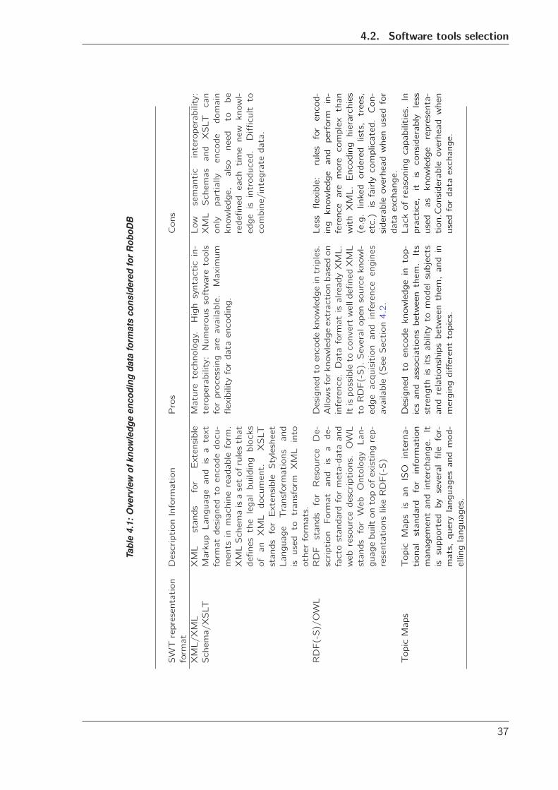
4.2. Software tools selection
Tabl
e4.
1:O
verv
iew
ofkn
owle
dge
enco
ding
data
form
ats
cons
ider
edfo
rR
oboD
B
SWTrepresentation
format
DescriptionInformation
Pros
Cons
XML/XML
Schema/XSLT
XMLstandsforExtensible
MarkupLanguageandisatext
formatdesignedtoencodedocu-
mentsinmachinereadableform.
XMLSchemaisasetofrulesthat
definesthelegalbuildingblocks
ofanXMLdocument.
XSLT
standsforExtensibleStylesheet
LanguageTransformationsand
isusedtotransformXMLinto
otherformats.
Maturetechnology.Highsyntacticin-
teroperability:Numeroussoftwaretools
forprocessingareavailable.Maximum
flexibilityfordataencoding.
Lowsemanticinteroperability:
XMLSchemasandXSLTcan
onlypartiallyencodedomain
knowledge,alsoneedtobe
redefinedeachtimenewknowl-
edgeisintroduced.Difficultto
combine/integratedata.
RDF(-S)/OWL
RDFstandsforResourceDe-
scriptionFormatandisade-
factostandardformeta-dataand
webresourcedescriptions.OWL
standsforWebOntologyLan-
guagebuiltontopofexistingrep-
resentationslikeRDF(-S)
Designedtoencodeknowledgeintriples.
Allowsforknowledgeextractionbasedon
inference.DataformatisalreadyXML.
ItispossibletoconvertwelldefinedXML
toRDF(-S).Severalopensourceknowl-
edgeacquisitionandinferenceengines
available(SeeSection4.2.
Lessflexible:rulesforencod-
ingknowledgeandperformin-
ferencearemorecomplexthan
withXML.Encodinghierarchies
(e.g.linkedorderedlists,trees,
etc.)isfairlycomplicated.Con-
siderableoverheadwhenusedfor
dataexchange.
TopicMaps
TopicMapsisanISOinterna-
tionalstandardforinformation
managementandinterchange.It
issupportedbyseveralfilefor-
mats,querylanguagesandmod-
ellinglanguages.
Designedtoencodeknowledgeintop-
icsandassociationsbetweenthem.Its
strengthisitsabilitytomodelsubjects
andrelationshipsbetweenthem,andin
mergingdifferenttopics.
Lackofreasoningcapabilities.In
practice,itisconsiderablyless
usedasknowledgerepresenta-
tion.Considerableoverheadwhen
usedfordataexchange.
37
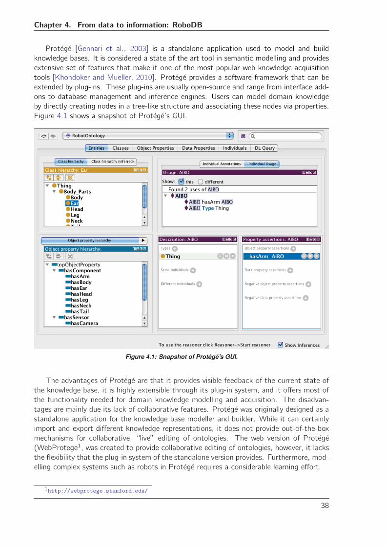
Chapter 4. From data to information: RoboDB
Protege [Gennari et al., 2003] is a standalone application used to model and build
knowledge bases. It is considered a state of the art tool in semantic modelling and provides
extensive set of features that make it one of the most popular web knowledge acquisition
tools [Khondoker and Mueller, 2010]. Protege provides a software framework that can be
extended by plug-ins. These plug-ins are usually open-source and range from interface add-
ons to database management and inference engines. Users can model domain knowledge
by directly creating nodes in a tree-like structure and associating these nodes via properties.
Figure 4.1 shows a snapshot of Protege’s GUI.
Figure 4.1: Snapshot of Protege’s GUI.
The advantages of Protege are that it provides visible feedback of the current state of
the knowledge base, it is highly extensible through its plug-in system, and it offers most of
the functionality needed for domain knowledge modelling and acquisition. The disadvan-
tages are mainly due its lack of collaborative features. Protege was originally designed as a
standalone application for the knowledge base modeller and builder. While it can certainly
import and export different knowledge representations, it does not provide out-of-the-box
mechanisms for collaborative, “live” editing of ontologies. The web version of Protege
(WebProtege1, was created to provide collaborative editing of ontologies, however, it lacks
the flexibility that the plug-in system of the standalone version provides. Furthermore, mod-
elling complex systems such as robots in Protege requires a considerable learning effort.
1http://webprotege.stanford.edu/
38
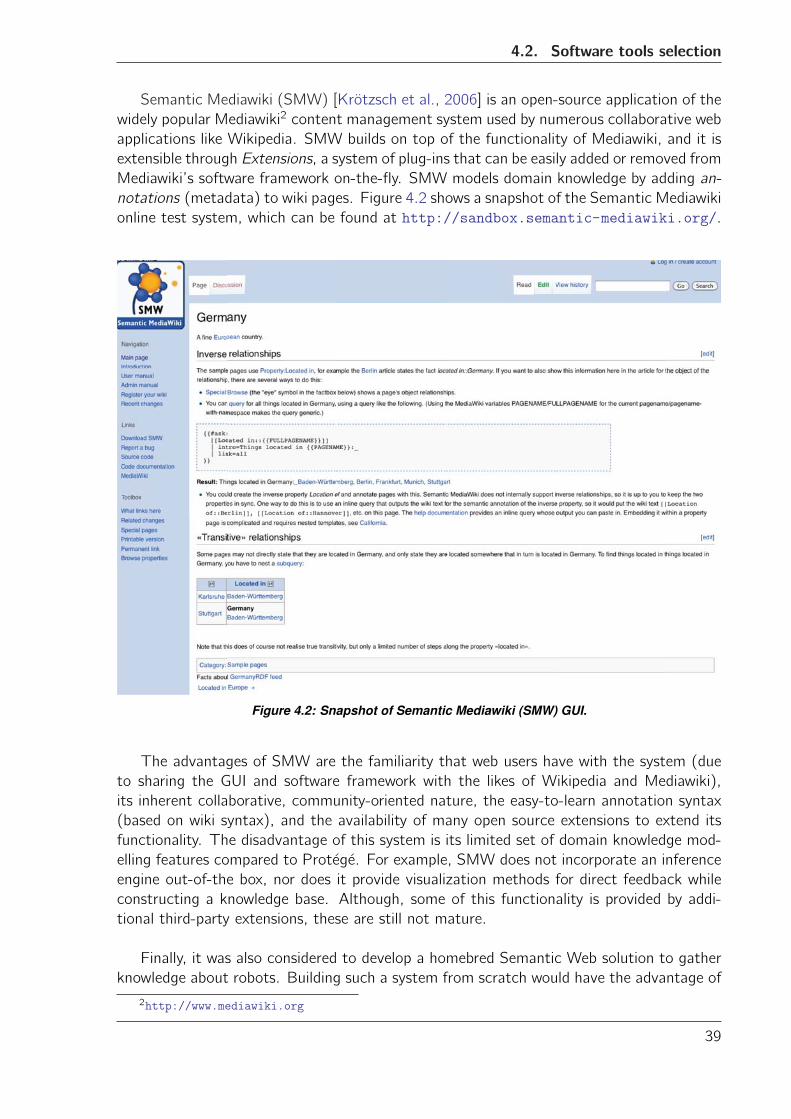
4.2. Software tools selection
Semantic Mediawiki (SMW) [Krotzsch et al., 2006] is an open-source application of the
widely popular Mediawiki2 content management system used by numerous collaborative web
applications like Wikipedia. SMW builds on top of the functionality of Mediawiki, and it is
extensible through Extensions, a system of plug-ins that can be easily added or removed from
Mediawiki’s software framework on-the-fly. SMW models domain knowledge by adding an-
notations (metadata) to wiki pages. Figure 4.2 shows a snapshot of the Semantic Mediawiki
online test system, which can be found at http://sandbox.semantic-mediawiki.org/.
Figure 4.2: Snapshot of Semantic Mediawiki (SMW) GUI.
The advantages of SMW are the familiarity that web users have with the system (due
to sharing the GUI and software framework with the likes of Wikipedia and Mediawiki),
its inherent collaborative, community-oriented nature, the easy-to-learn annotation syntax
(based on wiki syntax), and the availability of many open source extensions to extend its
functionality. The disadvantage of this system is its limited set of domain knowledge mod-
elling features compared to Protege. For example, SMW does not incorporate an inference
engine out-of-the box, nor does it provide visualization methods for direct feedback while
constructing a knowledge base. Although, some of this functionality is provided by addi-
tional third-party extensions, these are still not mature.
Finally, it was also considered to develop a homebred Semantic Web solution to gather
knowledge about robots. Building such a system from scratch would have the advantage of
2http://www.mediawiki.org
39
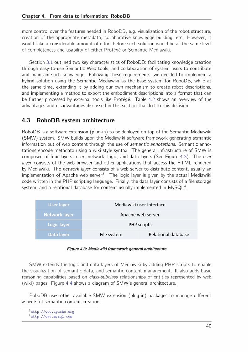
Chapter 4. From data to information: RoboDB
more control over the features needed in RoboDB, e.g. visualization of the robot structure,
creation of the appropriate metadata, collaborative knowledge building, etc. However, it
would take a considerable amount of effort before such solution would be at the same level
of completeness and usability of either Protege or Semantic Mediawiki.
Section 3.1 outlined two key characteristics of RoboDB: facilitating knowledge creation
through easy-to-use Semantic Web tools, and collaboration of system users to contribute
and maintain such knowledge. Following these requirements, we decided to implement a
hybrid solution using the Semantic Mediawiki as the base system for RoboDB, while at
the same time, extending it by adding our own mechanism to create robot descriptions,
and implementing a method to export the embodiment descriptions into a format that can
be further processed by external tools like Protege. Table 4.2 shows an overview of the
advantages and disadvantages discussed in this section that led to this decision.
4.3 RoboDB system architecture
RoboDB is a software extension (plug-in) to be deployed on top of the Semantic Mediawiki
(SMW) system. SMW builds upon the Mediawiki software framework generating semantic
information out of web content through the use of semantic annotations. Semantic anno-
tations encode metadata using a wiki-style syntax. The general infrastructure of SMW is
composed of four layers: user, network, logic, and data layers (See Figure 4.3). The user
layer consists of the web browser and other applications that access the HTML rendered
by Mediawiki. The network layer consists of a web server to distribute content, usually an
implementation of Apache web server3. The logic layer is given by the actual Mediawiki
code written in the PHP scripting language. Finally, the data layer consists of a file storage
system, and a relational database for content usually implemented in MySQL4.
� ������� ��� ������������� ���
������������ �� ���������������
�������� �����������
��������� ���������� �� ��� ��� � � ���
Figure 4.3: Mediawiki framework general architecture
SMW extends the logic and data layers of Mediawiki by adding PHP scripts to enable
the visualization of semantic data, and semantic content management. It also adds basic
reasoning capabilities based on class-subclass relationships of entities represented by web
(wiki) pages. Figure 4.4 shows a diagram of SMW’s general architecture.
RoboDB uses other available SMW extension (plug-in) packages to manage different
aspects of semantic content creation:
3http://www.apache.org4http://www.mysql.com
40
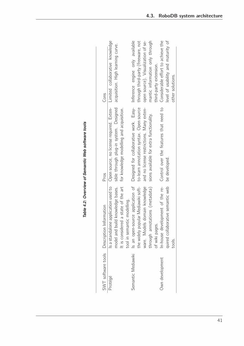
4.3. RoboDB system architecture
Tabl
e4.
2:O
verv
iew
ofS
eman
ticW
ebso
ftw
are
tool
s
SWTsoftwaretoolsDescriptionInformation
Pros
Cons
Protege
Isastandaloneapplicationusedto
modelandbuildknowledgebases.
Itisconsideredastateoftheart
toolinsemanticmodelling.
Opensource,nolicenserequired.Exten-
siblethroughplug-insystem.Designed
forknowledgemodellingandacquisition.
Limitedcollaborativeknowledge
acquisition.Highlearningcurve.
SemanticMediawikiIsanopen-sourceapplicationof
thewidelypopularMediawikisoft-
ware.Modelsdomainknowledge
throughannotations(metadata)
ofwikipages.
Designedforcollaborativework.Easy-
to-learnannotationsyntax.Opensource
andnolicenserestrictions.Manyexten-
sionsavailableforextrafunctionality.
Inferenceengineonlyavailable
throughthird-party(freeware,not
opensource).Visualizationofse-
manticinformationonlythrough
third-partyextension.
Owndevelopment
In-housedevelopmentofthere-
quiredcollaborativesemanticweb
tools.
Controloverthefeaturesthatneedto
bedeveloped.
Considerableefforttoachievethe
levelofusabilityandmaturityof
othersolutions.
41
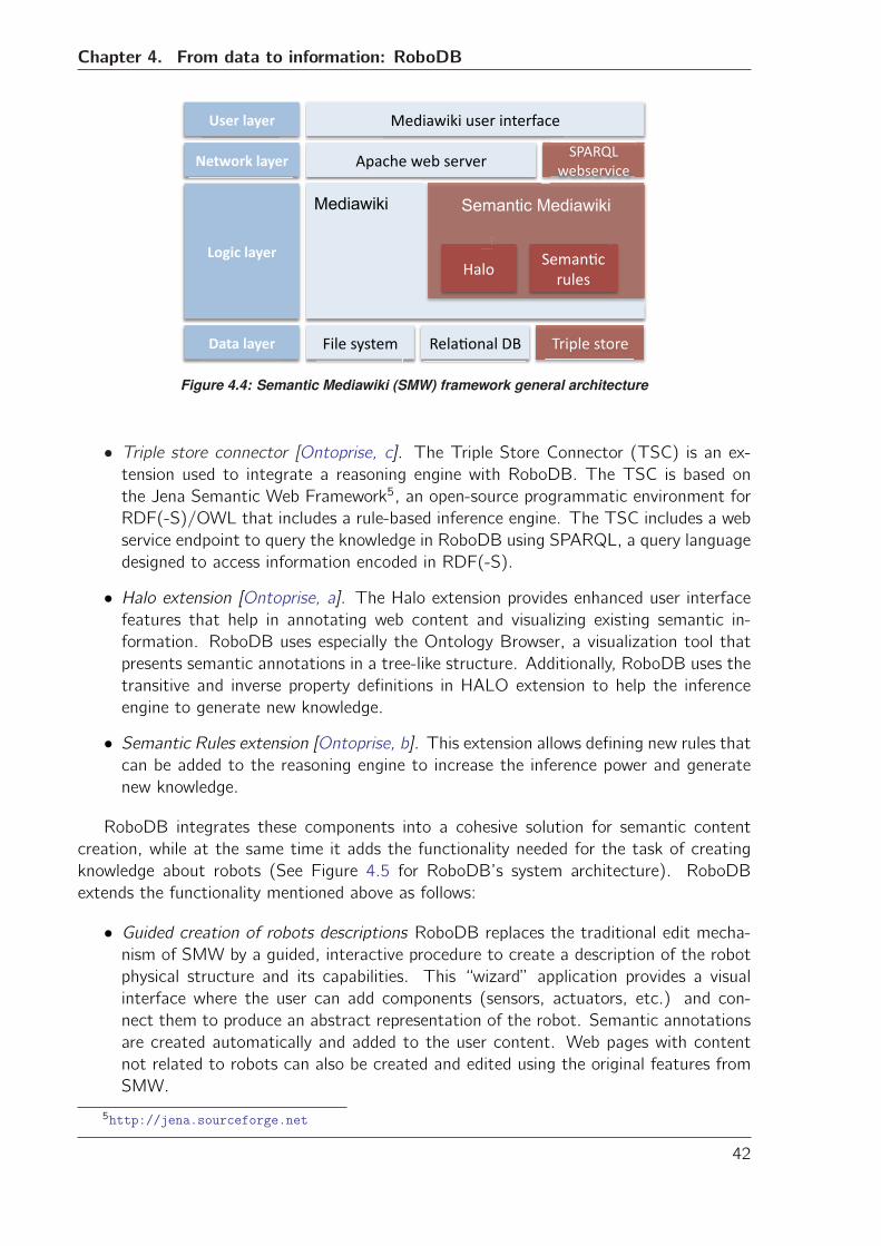
Chapter 4. From data to information: RoboDB
Mediawiki
�� ��������� ���� !����� � �������! ��
Semantic Mediawiki
���!����� �� "����
�������#����� $� ��������
#���� $����
�����#����"�� ���� ������ �������
������������
��������
���������
Figure 4.4: Semantic Mediawiki (SMW) framework general architecture
• Triple store connector [Ontoprise, c]. The Triple Store Connector (TSC) is an ex-tension used to integrate a reasoning engine with RoboDB. The TSC is based on
the Jena Semantic Web Framework5, an open-source programmatic environment for
RDF(-S)/OWL that includes a rule-based inference engine. The TSC includes a web
service endpoint to query the knowledge in RoboDB using SPARQL, a query language
designed to access information encoded in RDF(-S).
• Halo extension [Ontoprise, a]. The Halo extension provides enhanced user interfacefeatures that help in annotating web content and visualizing existing semantic in-
formation. RoboDB uses especially the Ontology Browser, a visualization tool that
presents semantic annotations in a tree-like structure. Additionally, RoboDB uses the
transitive and inverse property definitions in HALO extension to help the inference
engine to generate new knowledge.
• Semantic Rules extension [Ontoprise, b]. This extension allows defining new rules thatcan be added to the reasoning engine to increase the inference power and generate
new knowledge.
RoboDB integrates these components into a cohesive solution for semantic content
creation, while at the same time it adds the functionality needed for the task of creating
knowledge about robots (See Figure 4.5 for RoboDB’s system architecture). RoboDB
extends the functionality mentioned above as follows:
• Guided creation of robots descriptions RoboDB replaces the traditional edit mecha-nism of SMW by a guided, interactive procedure to create a description of the robot
physical structure and its capabilities. This “wizard” application provides a visual
interface where the user can add components (sensors, actuators, etc.) and con-
nect them to produce an abstract representation of the robot. Semantic annotations
are created automatically and added to the user content. Web pages with content
not related to robots can also be created and edited using the original features from
SMW.
5http://jena.sourceforge.net
42
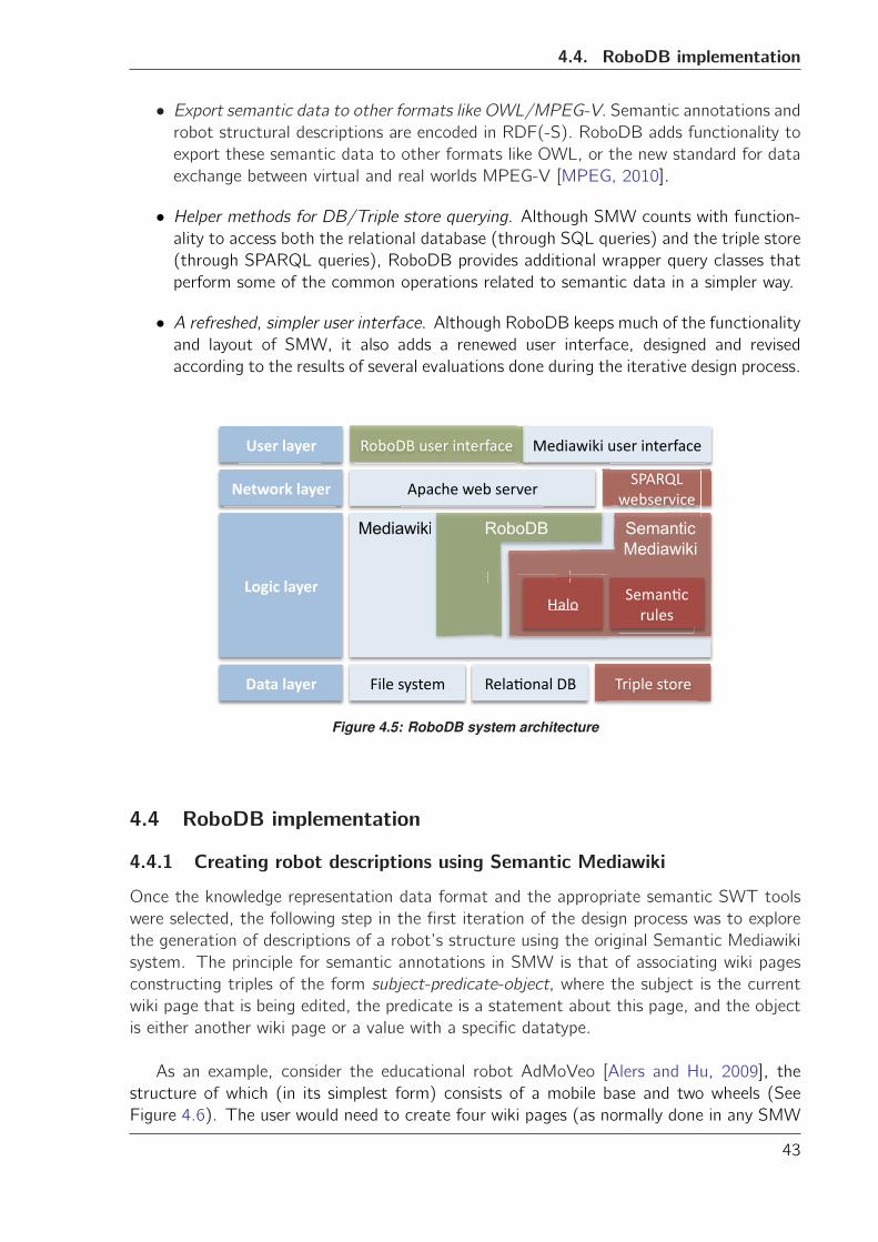
4.4. RoboDB implementation
• Export semantic data to other formats like OWL/MPEG-V. Semantic annotations androbot structural descriptions are encoded in RDF(-S). RoboDB adds functionality to
export these semantic data to other formats like OWL, or the new standard for data
exchange between virtual and real worlds MPEG-V [MPEG, 2010].
• Helper methods for DB/Triple store querying. Although SMW counts with function-ality to access both the relational database (through SQL queries) and the triple store
(through SPARQL queries), RoboDB provides additional wrapper query classes that
perform some of the common operations related to semantic data in a simpler way.
• A refreshed, simpler user interface. Although RoboDB keeps much of the functionalityand layout of SMW, it also adds a renewed user interface, designed and revised
according to the results of several evaluations done during the iterative design process.
Mediawiki
������������ ���� !����� � �������! ��
Semantic Mediawiki
���!����� �� "����
�������#����� $� ��������
#���� $����
�����#����"�� ���� �����
i
���!�
RoboDB
�!�!��"�� ���� ������ �������
������������
��������
���������
Figure 4.5: RoboDB system architecture
4.4 RoboDB implementation
4.4.1 Creating robot descriptions using Semantic Mediawiki
Once the knowledge representation data format and the appropriate semantic SWT tools
were selected, the following step in the first iteration of the design process was to explore
the generation of descriptions of a robot’s structure using the original Semantic Mediawiki
system. The principle for semantic annotations in SMW is that of associating wiki pages
constructing triples of the form subject-predicate-object, where the subject is the current
wiki page that is being edited, the predicate is a statement about this page, and the object
is either another wiki page or a value with a specific datatype.
As an example, consider the educational robot AdMoVeo [Alers and Hu, 2009], the
structure of which (in its simplest form) consists of a mobile base and two wheels (See
Figure 4.6). The user would need to create four wiki pages (as normally done in any SMW
43
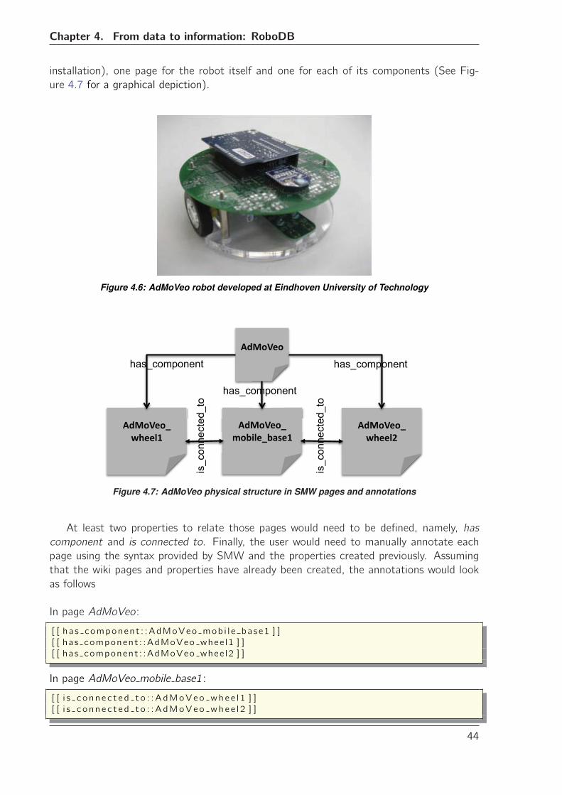
Chapter 4. From data to information: RoboDB
installation), one page for the robot itself and one for each of its components (See Fig-
ure 4.7 for a graphical depiction).
Figure 4.6: AdMoVeo robot developed at Eindhoven University of Technology
�������
�����������������
������������
�������������
has_component has_component
has_component
is_c
onne
cted
_to
is_c
onne
cted
_to
Figure 4.7: AdMoVeo physical structure in SMW pages and annotations
At least two properties to relate those pages would need to be defined, namely, has
component and is connected to. Finally, the user would need to manually annotate each
page using the syntax provided by SMW and the properties created previously. Assuming
that the wiki pages and properties have already been created, the annotations would look
as follows
In page AdMoVeo:
[ [ ha s component : :AdMoVeo mob i l e ba se1 ] ]
[ [ has component : :AdMoVeo whee l1 ] ]
[ [ has component : :AdMoVeo whee l2 ] ]
In page AdMoVeo mobile base1 :
[ [ i s c o nn e c t e d t o : :AdMoVeo whe e l 1 ] ]
[ [ i s c o nn e c t e d t o : :AdMoVeo whe e l 2 ] ]
44
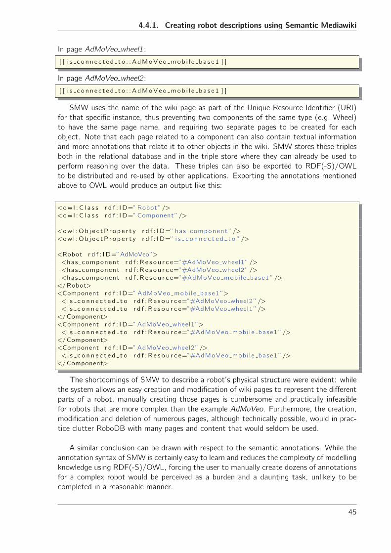
4.4.1. Creating robot descriptions using Semantic Mediawiki
In page AdMoVeo wheel1 :
[ [ i s c o n n e c t e d t o : : A dMoVeo mob i l e b a s e 1 ] ]
In page AdMoVeo wheel2 :
[ [ i s c o n n e c t e d t o : : A dMoVeo mob i l e b a s e 1 ] ]
SMW uses the name of the wiki page as part of the Unique Resource Identifier (URI)
for that specific instance, thus preventing two components of the same type (e.g. Wheel)
to have the same page name, and requiring two separate pages to be created for each
object. Note that each page related to a component can also contain textual information
and more annotations that relate it to other objects in the wiki. SMW stores these triples
both in the relational database and in the triple store where they can already be used to
perform reasoning over the data. These triples can also be exported to RDF(-S)/OWL
to be distributed and re-used by other applications. Exporting the annotations mentioned
above to OWL would produce an output like this:
<ow l : C l a s s r d f : I D=”Robot”/>
<ow l : C l a s s r d f : I D=”Component”/>
<ow l :Ob j e c tP r o p e r t y r d f : I D=” has component ”/>
<ow l :Ob j e c tP r o p e r t y r d f : I D=” i s c o n n e c t e d t o ”/>
<Robot r d f : I D=”AdMoVeo”>
<has component r d f : R e s o u r c e=”#AdMoVeo wheel1”/>
<has component r d f : R e s o u r c e=”#AdMoVeo wheel2”/>
<has component r d f : R e s o u r c e=”#AdMoVeo mobi le base1 ”/>
</Robot>
<Component r d f : I D=”AdMoVeo mobi le base1 ”>
< i s c o n n e c t e d t o r d f : R e s o u r c e=”#AdMoVeo wheel2”/>
< i s c o n n e c t e d t o r d f : R e s o u r c e=”#AdMoVeo wheel1”/>
</Component>
<Component r d f : I D=”AdMoVeo wheel1”>
< i s c o n n e c t e d t o r d f : R e s o u r c e=”#AdMoVeo mobi le base1 ”/>
</Component>
<Component r d f : I D=”AdMoVeo wheel2”/>
< i s c o n n e c t e d t o r d f : R e s o u r c e=”#AdMoVeo mobi le base1 ”/>
</Component>
The shortcomings of SMW to describe a robot’s physical structure were evident: while
the system allows an easy creation and modification of wiki pages to represent the different
parts of a robot, manually creating those pages is cumbersome and practically infeasible
for robots that are more complex than the example AdMoVeo. Furthermore, the creation,
modification and deletion of numerous pages, although technically possible, would in prac-
tice clutter RoboDB with many pages and content that would seldom be used.
A similar conclusion can be drawn with respect to the semantic annotations. While the
annotation syntax of SMW is certainly easy to learn and reduces the complexity of modelling
knowledge using RDF(-S)/OWL, forcing the user to manually create dozens of annotations
for a complex robot would be perceived as a burden and a daunting task, unlikely to be
completed in a reasonable manner.
45
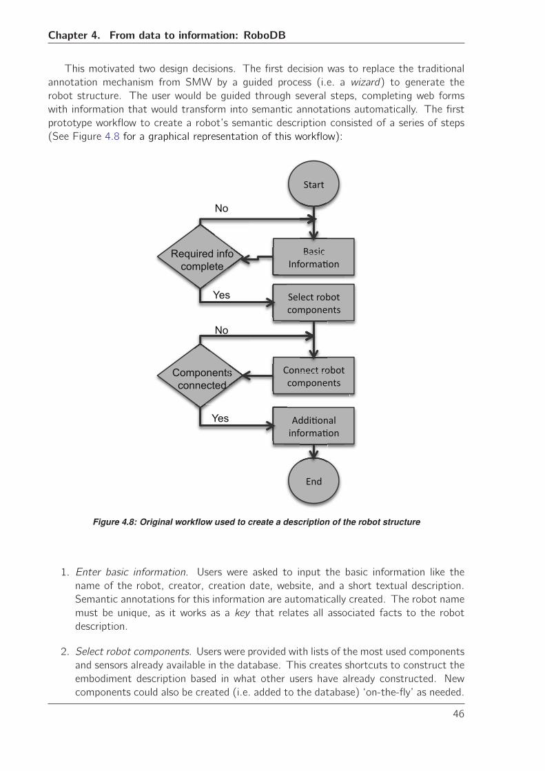
Chapter 4. From data to information: RoboDB
This motivated two design decisions. The first decision was to replace the traditional
annotation mechanism from SMW by a guided process (i.e. a wizard) to generate the
robot structure. The user would be guided through several steps, completing web forms
with information that would transform into semantic annotations automatically. The first
prototype workflow to create a robot’s semantic description consisted of a series of steps
(See Figure 4.8 for a graphical representation of this workflow):
�� ���
� ��������� ���
�����������������������
�����������������������
������ ������� ���
����
Required info complete
Components connected
o
s ���� ��
� ���
Yes
Yes
No
No
Figure 4.8: Original workflow used to create a description of the robot structure
1. Enter basic information. Users were asked to input the basic information like the
name of the robot, creator, creation date, website, and a short textual description.
Semantic annotations for this information are automatically created. The robot name
must be unique, as it works as a key that relates all associated facts to the robot
description.
2. Select robot components. Users were provided with lists of the most used components
and sensors already available in the database. This creates shortcuts to construct the
embodiment description based in what other users have already constructed. New
components could also be created (i.e. added to the database) ‘on-the-fly’ as needed.
46
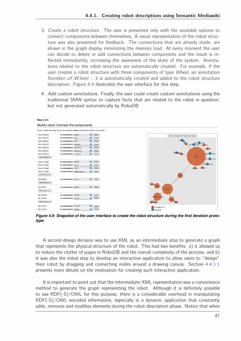
4.4.1. Creating robot descriptions using Semantic Mediawiki
3. Create a robot structure. The user is presented only with the available options to
connect components between themselves. A visual representation of the robot struc-
ture was also presented for feedback. The connections that are already made, are
shown in the graph display minimizing the memory load. At every moment the user
can decide to delete or add connections between components and the result is re-
flected immediately, increasing the awareness of the state of the system. Annota-
tions related to the robot structure are automatically created. For example, if the
user creates a robot structure with three components of type Wheel, an annotation
Number of Wheel :: 3 is automatically created and added to the robot structure
description. Figure 4.9 illustrates the user interface for this step.
4. Add custom annotations. Finally, the user could create custom annotations using the
traditional SMW syntax to capture facts that are related to the robot in question,
but not generated automatically by RoboDB
Figure 4.9: Snapshot of the user interface to create the robot structure during the first iteration proto-type
A second design decision was to use XML as an intermediate step to generate a graph
that represents the physical structure of the robot. This had two benefits: a) it allowed us
to reduce the clutter of pages in RoboDB and the overall complexity of the process, and b)
it was also the initial step to develop an interactive application to allow users to “design”
their robot by dragging and connecting nodes around a drawing canvas. Section 4.4.1.1
presents more details on the motivation for creating such interactive application.
It is important to point out that the intermediate XML representation was a convenience
method to generate the graph representing the robot. Although it is definitely possible
to use RDF(-S)/OWL for this purpose, there is a considerable overhead in manipulating
RDF(-S)/OWL encoded information, especially in a dynamic application that constantly
adds, removes and modifies elements during the robot description phase. Notice that when
47
Chapter 4. From data to information: RoboDB
the user finishes describing a robot, the intermediate XML graph is converted into OWL
entities. The OWL-encoded version of the graph is then integrated into the RDF(-S)/OWL
encoded information about the robot collected in previous steps.
4.4.1.1 Heuristic evaluation
We conducted a heuristic evaluation on the usability of the first prototype based on the
principles described by Nielsen in [Nielsen, 1993]. The heuristics are simple and natural di-
alogue, speak the user’s language, minimize the user’s memory load, be consistent, provide
feedback, provide clearly marked exits, provide shortcuts, provide good error messages, and
error prevention. These heuristics are known as the nine principles of the usability checklist.
The technique used to assess usability resembles the one presented by Molich and Nielsen
in [Molich and Nielsen, 1990]. A small group of four HRI and systems design experts fol-
lowing were asked to provide feedback on the system prototype, and their observations
were mapped to the principles mentioned above. It must be noted that the assessment did
not follow the focus group methodology [Morgan, 1997, Nielsen, 1993] as the experts did
not convene at the same location to discuss about the system. Instead the experts were
approached separately.
Some of the conclusions obtained from this process were:
a) It is a good idea to subdivide the process of adding new information into consistent
steps. This reduces the memory load on the user, as he/she is not required to input all the
information about the robot structure at once. However, the process is still too complex
and requires too much scrolling and going back and forth. This could be greatly improved
by an interactive application to create the robot structure.
b) The same guided approach should be used for the modification of existing embodi-
ment descriptions. As a result, the system as a whole gains in consistency and the user can
quickly accommodate to the process by repetition.
c) The graph preview of the robot should be included on each step of the process of
adding or modifying an embodiment description. This gives appropriate, updated feedback
to the user, allowing him to spot errors at any stage of the process. It also helps reducing
the memory load imposed on the user.
d) Although wikis are indeed recognized by their user-friendliness, it is best to give a
refreshed image to RoboDB while keeping the easiness to use and the robustness of the
original system. The experts also mentioned that the overall acceptance and appreciation
of the system could be adversely affected by the incorrect perception that this was yet-
another-wiki-site, with repeated or incomplete information about robots. A refreshed user
interface and a clear, visible statement of what can be done with the system -with shortcuts
to examples- will contribute to avoid such perception.
We took these insights and fed them into the next iteration of the design process to
produce a second prototype for RoboDB.
48
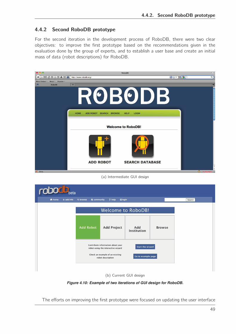
4.4.2. Second RoboDB prototype
4.4.2 Second RoboDB prototype
For the second iteration in the development process of RoboDB, there were two clear
objectives: to improve the first prototype based on the recommendations given in the
evaluation done by the group of experts, and to establish a user base and create an initial
mass of data (robot descriptions) for RoboDB.
(a) Intermediate GUI design
(b) Current GUI design
Figure 4.10: Example of two iterations of GUI design for RoboDB.
The efforts on improving the first prototype were focused on updating the user interface
49
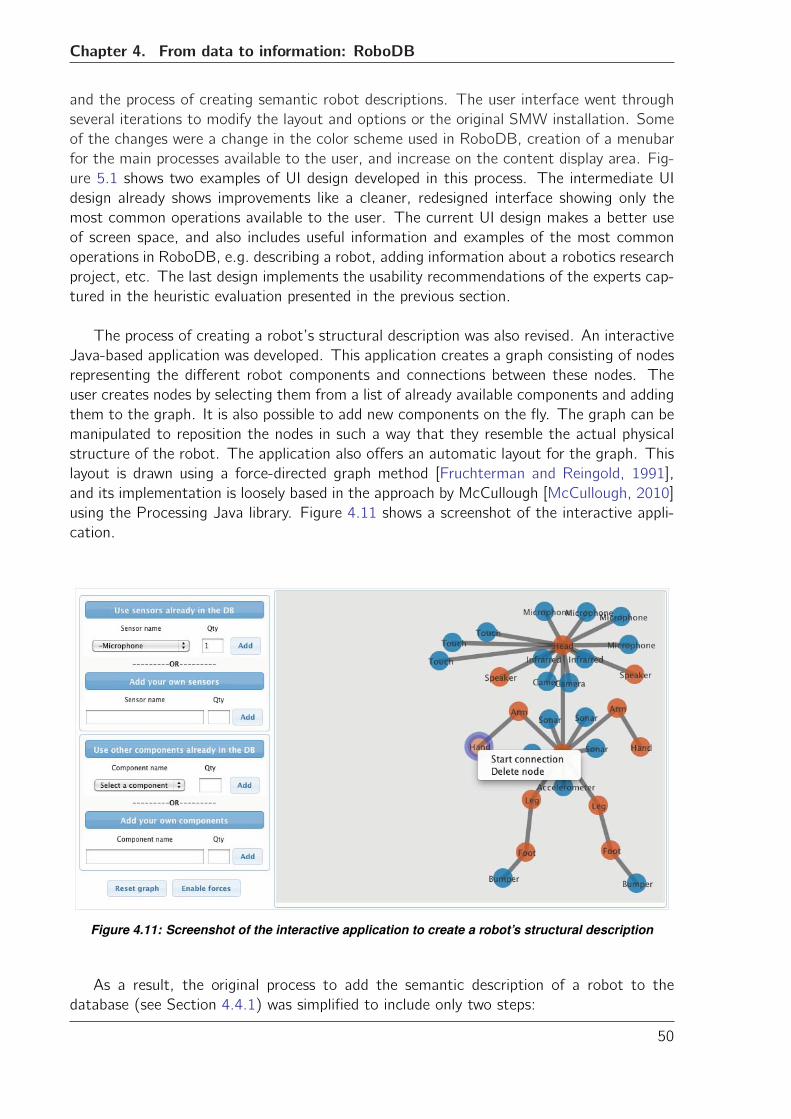
Chapter 4. From data to information: RoboDB
and the process of creating semantic robot descriptions. The user interface went through
several iterations to modify the layout and options or the original SMW installation. Some
of the changes were a change in the color scheme used in RoboDB, creation of a menubar
for the main processes available to the user, and increase on the content display area. Fig-
ure 5.1 shows two examples of UI design developed in this process. The intermediate UI
design already shows improvements like a cleaner, redesigned interface showing only the
most common operations available to the user. The current UI design makes a better use
of screen space, and also includes useful information and examples of the most common
operations in RoboDB, e.g. describing a robot, adding information about a robotics research
project, etc. The last design implements the usability recommendations of the experts cap-
tured in the heuristic evaluation presented in the previous section.
The process of creating a robot’s structural description was also revised. An interactive
Java-based application was developed. This application creates a graph consisting of nodes
representing the different robot components and connections between these nodes. The
user creates nodes by selecting them from a list of already available components and adding
them to the graph. It is also possible to add new components on the fly. The graph can be
manipulated to reposition the nodes in such a way that they resemble the actual physical
structure of the robot. The application also offers an automatic layout for the graph. This
layout is drawn using a force-directed graph method [Fruchterman and Reingold, 1991],
and its implementation is loosely based in the approach by McCullough [McCullough, 2010]
using the Processing Java library. Figure 4.11 shows a screenshot of the interactive appli-
cation.
Figure 4.11: Screenshot of the interactive application to create a robot’s structural description
As a result, the original process to add the semantic description of a robot to the
database (see Section 4.4.1) was simplified to include only two steps:
50
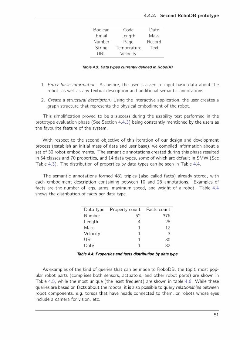
4.4.2. Second RoboDB prototype
Boolean Code Date
Email Length Mass
Number Page Record
String Temperature Text
URL Velocity
Table 4.3: Data types currently defined in RoboDB
1. Enter basic information. As before, the user is asked to input basic data about the
robot, as well as any textual description and additional semantic annotations.
2. Create a structural description. Using the interactive application, the user creates a
graph structure that represents the physical embodiment of the robot.
This simplification proved to be a success during the usability test performed in the
prototype evaluation phase (See Section 4.4.3) being constantly mentioned by the users as
the favourite feature of the system.
With respect to the second objective of this iteration of our design and development
process (establish an initial mass of data and user base), we compiled information about a
set of 30 robot embodiments. The semantic annotations created during this phase resulted
in 54 classes and 70 properties, and 14 data types, some of which are default in SMW (See
Table 4.3). The distribution of properties by data types can be seen in Table 4.4.
The semantic annotations formed 481 triples (also called facts) already stored, with
each embodiment description containing between 10 and 26 annotations. Examples of
facts are the number of legs, arms, maximum speed, and weight of a robot. Table 4.4
shows the distribution of facts per data type.
Data type Property count Facts count
Number 52 376
Length 4 28
Mass 1 12
Velocity 1 3
URL 1 30
Date 1 32
Table 4.4: Properties and facts distribution by data type
As examples of the kind of queries that can be made to RoboDB, the top 5 most pop-
ular robot parts (comprises both sensors, actuators, and other robot parts) are shown in
Table 4.5, while the most unique (the least frequent) are shown in table 4.6. While these
queries are based on facts about the robots, it is also possible to query relationships between
robot components, e.g. torsos that have heads connected to them, or robots whose eyes
include a camera for vision, etc.
51
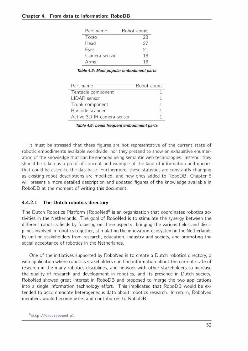
Chapter 4. From data to information: RoboDB
Part name Robot count
Torso 28
Head 27
Eyes 21
Camera sensor 18
Arms 18
Table 4.5: Most popular embodiment parts
Part name Robot count
Tentacle component 1
LIDAR sensor 1
Trunk component 1
Barcode scanner 1
Active 3D IR camera sensor 1
Table 4.6: Least frequent embodiment parts
It must be stressed that these figures are not representative of the current state of
robotic embodiments available worldwide, nor they pretend to show an exhaustive enumer-
ation of the knowledge that can be encoded using semantic web technologies. Instead, they
should be taken as a proof of concept and example of the kind of information and queries
that could be asked to the database. Furthermore, these statistics are constantly changing
as existing robot descriptions are modified, and new ones added to RoboDB. Chapter 5
will present a more detailed description and updated figures of the knowledge available in
RoboDB at the moment of writing this document.
4.4.2.1 The Dutch robotics directory
The Dutch Robotics Platform (RoboNed6 is an organization that coordinates robotics ac-
tivities in the Netherlands. The goal of RoboNed is to stimulate the synergy between the
different robotics fields by focusing on three aspects: bringing the various fields and disci-
plines involved in robotics together, stimulating the innovation-ecosystem in the Netherlands
by uniting stakeholders from research, education, industry and society, and promoting the
social acceptance of robotics in the Netherlands.
One of the initiatives supported by RoboNed is to create a Dutch robotics directory, a
web application where robotics stakeholders can find information about the current state of
research in the many robotics disciplines, and network with other stakeholders to increase
the quality of research and development in robotics, and its presence in Dutch society.
RoboNed showed great interest in RoboDB and proposed to merge the two applications
into a single information technology effort. This implicated that RoboDB would be ex-
tended to accommodate heterogeneous data about robotics research. In return, RoboNed
members would become users and contributors to RoboDB.
6http://www.roboned.nl
52
4.4.3. Usability evaluation
The Dutch robotics directory presented a classic scenario for the application of semantic
web technologies. Chunks of data needed to be linked to produce a network of information
that the user could navigate. RoboDB features like collaborative data generation, easy
semantic annotation syntax, and guided data input are well suited to this task.
Based on the previous experience with the first RoboDB prototype, a decision was made
by the author and the platform manager of RoboNed to also provide a guided process to
help RoboNed members to add information to RoboDB. In this case, the type of semantic
data to be generated was much simpler, as it only involved textual input. Therefore the
guided process consisted in two special web forms that collected the required information to
automatically create semantic annotations connecting robotics research projects to people,
institutions and robots. The GUI was also modified to include this new input processes (See
Figure 4.10b).
4.4.3 Usability evaluation
The evaluation of the second iteration of RoboDB consisted on a usability test carried out
with the cooperation of RoboNed members as users. Participants to the test were asked
to complete three tasks:
• Search for information about a specific robot.• Search for a robotics research project page and edit its contents by connecting aspecific robot to it.
• Add their own robot to RoboDB
In order to better capture the interaction with the system, participants were asked to
think aloud while completing the tasks. The thinking-aloud method [Van Someren et al.,
1994] was developed to understand the thought process of users in an effort to capture their
cognitive actions, the knowledge they use, and the strategies they employ. This method
helps to get a real “feel” for processes that are actually relevant to the potential users of
the system. Notes were taken during the administration of the test.
The measurement device was the System Usability Scale (SUS) questionnaire developed
by J. Brooke [Brooke, 1996]. The questionnaire consists of 10 items, each having a five-
point scale that ranges from Strongly Disagree to Strongly Agree. The maximum score is
100 and the minimum score is 0. There are five positive and five negative statements that
alternate to provide a view of subjective assessments of usability.
The SUS questionnaire tries to capture extreme expressions of the attitude of the user
towards the system. Therefore, the questionnaire must be administered after the respon-
dent used the system, but before any debriefing or discussion takes place. Participants were
asked to record their immediate response and to not think too much about the answers.
In addition to that, an adjective rating scale was added to the questionnaire, following
the suggestions from Bangor et al. [Bangor et al., 2009], which state that an adjective
scale that rates user-friendliness can help in more accurately interpreting the meaning of
53
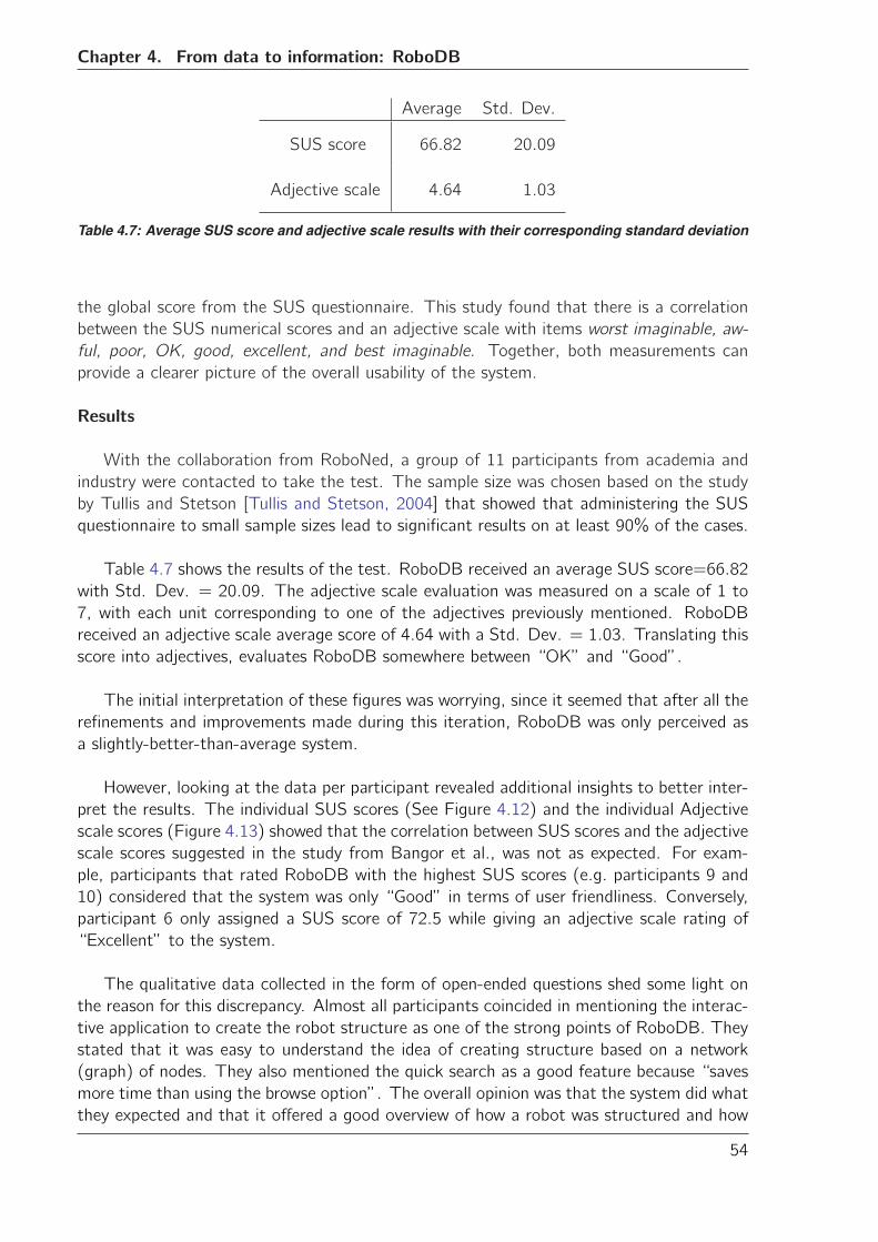
Chapter 4. From data to information: RoboDB
Average Std. Dev.
SUS score 66.82 20.09
Adjective scale 4.64 1.03
Table 4.7: Average SUS score and adjective scale results with their corresponding standard deviation
the global score from the SUS questionnaire. This study found that there is a correlation
between the SUS numerical scores and an adjective scale with items worst imaginable, aw-
ful, poor, OK, good, excellent, and best imaginable. Together, both measurements can
provide a clearer picture of the overall usability of the system.
Results
With the collaboration from RoboNed, a group of 11 participants from academia and
industry were contacted to take the test. The sample size was chosen based on the study
by Tullis and Stetson [Tullis and Stetson, 2004] that showed that administering the SUS
questionnaire to small sample sizes lead to significant results on at least 90% of the cases.
Table 4.7 shows the results of the test. RoboDB received an average SUS score=66.82
with Std. Dev. = 20.09. The adjective scale evaluation was measured on a scale of 1 to
7, with each unit corresponding to one of the adjectives previously mentioned. RoboDB
received an adjective scale average score of 4.64 with a Std. Dev. = 1.03. Translating this
score into adjectives, evaluates RoboDB somewhere between “OK” and “Good”.
The initial interpretation of these figures was worrying, since it seemed that after all the
refinements and improvements made during this iteration, RoboDB was only perceived as
a slightly-better-than-average system.
However, looking at the data per participant revealed additional insights to better inter-
pret the results. The individual SUS scores (See Figure 4.12) and the individual Adjective
scale scores (Figure 4.13) showed that the correlation between SUS scores and the adjective
scale scores suggested in the study from Bangor et al., was not as expected. For exam-
ple, participants that rated RoboDB with the highest SUS scores (e.g. participants 9 and
10) considered that the system was only “Good” in terms of user friendliness. Conversely,
participant 6 only assigned a SUS score of 72.5 while giving an adjective scale rating of
“Excellent” to the system.
The qualitative data collected in the form of open-ended questions shed some light on
the reason for this discrepancy. Almost all participants coincided in mentioning the interac-
tive application to create the robot structure as one of the strong points of RoboDB. They
stated that it was easy to understand the idea of creating structure based on a network
(graph) of nodes. They also mentioned the quick search as a good feature because “saves
more time than using the browse option”. The overall opinion was that the system did what
they expected and that it offered a good overview of how a robot was structured and how
54
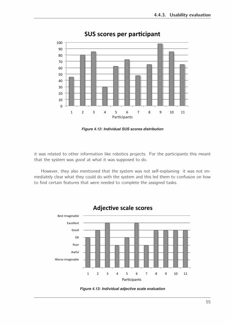
4.4.3. Usability evaluation
��
���
���
���
���
���
���
���
��
��
����
�� �� �� �� �� �� �� � � ��� ���
��������������� �
� ����� ����
Figure 4.12: Individual SUS scores distribution
it was related to other information like robotics projects. For the participants this meant
that the system was good at what it was supposed to do.
However, they also mentioned that the system was not self-explaining: it was not im-
mediately clear what they could do with the system and this led them to confusion on how
to find certain features that were needed to complete the assigned tasks.
�� %� &� '� (� )� *� +� ,� ��� ���
���������������������������������
��������
����
���
�����
������
�����������������
������������
Figure 4.13: Individual adjective scale evaluation
55
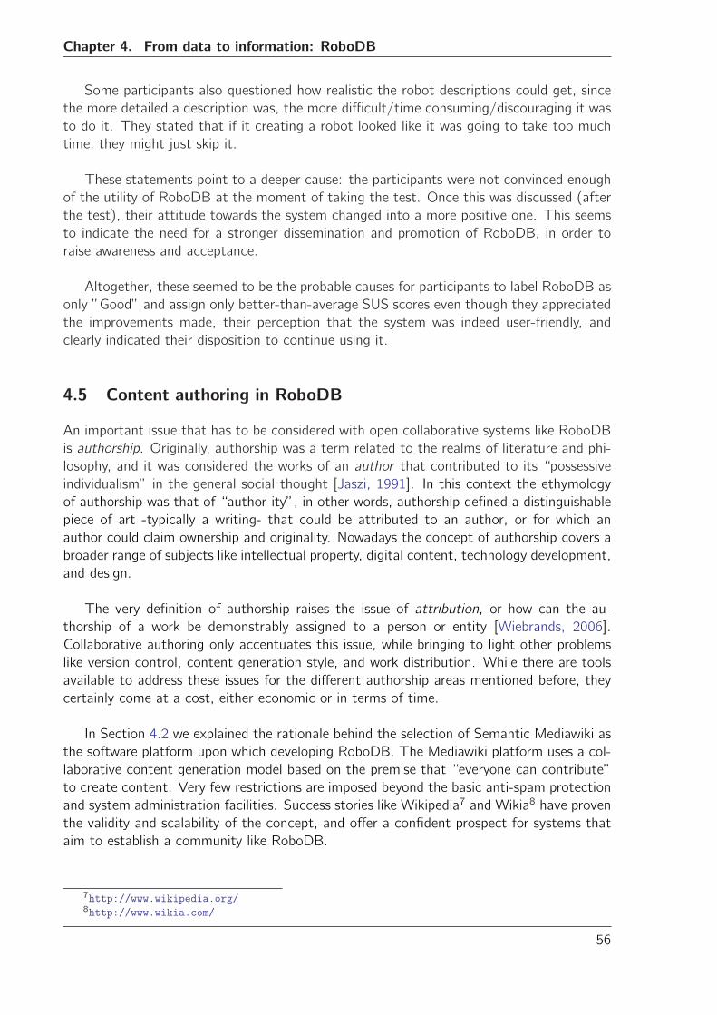
Chapter 4. From data to information: RoboDB
Some participants also questioned how realistic the robot descriptions could get, since
the more detailed a description was, the more difficult/time consuming/discouraging it was
to do it. They stated that if it creating a robot looked like it was going to take too much
time, they might just skip it.
These statements point to a deeper cause: the participants were not convinced enough
of the utility of RoboDB at the moment of taking the test. Once this was discussed (after
the test), their attitude towards the system changed into a more positive one. This seems
to indicate the need for a stronger dissemination and promotion of RoboDB, in order to
raise awareness and acceptance.
Altogether, these seemed to be the probable causes for participants to label RoboDB as
only ”Good” and assign only better-than-average SUS scores even though they appreciated
the improvements made, their perception that the system was indeed user-friendly, and
clearly indicated their disposition to continue using it.
4.5 Content authoring in RoboDB
An important issue that has to be considered with open collaborative systems like RoboDB
is authorship. Originally, authorship was a term related to the realms of literature and phi-
losophy, and it was considered the works of an author that contributed to its “possessive
individualism” in the general social thought [Jaszi, 1991]. In this context the ethymology
of authorship was that of “author-ity”, in other words, authorship defined a distinguishable
piece of art -typically a writing- that could be attributed to an author, or for which an
author could claim ownership and originality. Nowadays the concept of authorship covers a
broader range of subjects like intellectual property, digital content, technology development,
and design.
The very definition of authorship raises the issue of attribution, or how can the au-
thorship of a work be demonstrably assigned to a person or entity [Wiebrands, 2006].
Collaborative authoring only accentuates this issue, while bringing to light other problems
like version control, content generation style, and work distribution. While there are tools
available to address these issues for the different authorship areas mentioned before, they
certainly come at a cost, either economic or in terms of time.
In Section 4.2 we explained the rationale behind the selection of Semantic Mediawiki as
the software platform upon which developing RoboDB. The Mediawiki platform uses a col-
laborative content generation model based on the premise that “everyone can contribute”
to create content. Very few restrictions are imposed beyond the basic anti-spam protection
and system administration facilities. Success stories like Wikipedia7 and Wikia8 have proven
the validity and scalability of the concept, and offer a confident prospect for systems that
aim to establish a community like RoboDB.
7http://www.wikipedia.org/8http://www.wikia.com/
56
4.5. Content authoring in RoboDB
However, there are still issues that must be taken into account. In practice, it has been
observed that when unchecked, content in Mediawiki systems can grow until it becomes
a “wiki jungle”, a maze of uncontrolled pages that “nobody can make heads or tails of”
[Wiebrands, 2006]. Two solution approaches to this problem are common: the appoint-
ment of a gardener to “clean up” the content, and the creation of a walled garden to keep
sections of content protected from abuse. The first approach is the one followed by public
sites like Wikipedia, where a group of moderators are in charge of ensuring the quality of
the content. Note that in practice, the same authors of content are the ones that identify
attribution issues and raise awareness on quality problems, effectively creating a sustain-
able self-maintenance mechanism. The second approach is used in corporate environments
where access to large content sections -and sometimes, even to the complete system- are
restricted to a few users that make sure that the content is appropriately categorized and
of acceptable quality.
The aim of RoboDB is to become a system of reference content for the robotics com-
munity. Therefore, RoboDB follows in the footsteps of public systems like Wikipedia and
encourages every visitor to contribute their own content. At the same time, members of
the RoboNed community 9 agreed to act as gardeners for the initial system rollout. I believe
this is a sensible decision, as system administrators and moderators of RoboDB should have
a substantial knowledge of robotics to be able to better assess the quality of the information
stored in the system. One must not think, however, that this is the only sufficient solution
to the problem. For example, an alternative to achieve sustainable content creation and
management is to use the semantic information already contained in RoboDB to prevent
“mistakes”, or at least, to intelligently and adaptively inform the user about existing infor-
mation and guide him/her through the process of content creation. The first steps were
already taken in RoboDB with the guided approaches to create descriptions of robot phys-
ical structures. Nonetheless, there is more investigation and development needed in this
direction.
Finally, an issue related to authoring is community engagement. No content will be
authored in RoboDB if the community does not engage in contributing to it. At the same
time, getting the interest of communities other than robotics might ensure the long term
viability of the system, as those communities can turn into future consumers of robotic
products and therefore, active users of the system. Previous work by Osman-Schlegel
et al. [Osman-Schlegel et al., 2011] using Mediawiki systems in education and training
activities show that although it succeeded in engaging students to work online in their
assignments, there are still challenges to overcome in order to fully accomplish this goal.
The most notable challenge is the set of skills required to use the Mediawiki system which
varies greatly from student to student. Although during the course of this PhD project
no investigation was made into this area, this is a promising avenue of future research to
increase the impact of RoboDB not only at the local level, but also internationally.
9Initially Dr. Heico Sandee and Ir. Ditske Kranenburg, Platform Managers for RoboNed are appointed
as system administrators and moderators, with more members expressing their interest in becoming system
moderators.
57
Chapter 4. From data to information: RoboDB
4.6 Concluding remarks
This chapter has presented RoboDB, a system based on SWT designed to gather infor-
mation about robots. Key elements showed here were the motivation for the selection of
the different technologies and tools that are integrated in RoboDB, as well as the design
decisions and lessons learned taken during the system implementation and evaluation using
the iterative (spiral) design methodology.
RoboDB has also exhibited versatility and flexibility by easily extending to accommodate
the Dutch robotics directory, an example of a classic scenario for SWT application.
The different evaluations performed over RoboDB show a cohesive and stable system,
with the potential to become a useful tool not only for the generation of knowledge neces-
sary for interoperability between virtual agents and real robots, but as a general knowledge
hub for the robotics community in itself. A confirmation of this last point is the decision of
RoboNed of taking over the development of RoboDB at the end of this PhD project (See
Appendix A) and continue with its promotion and use initially within the Dutch robotics
community, and later on at the international level.
RoboDB also shows some limitations when describing robots using Semantic Web tech-
nologies. Some of these are inherited from the tools selected as the base of the system
(i.e. the complexity of describing a robot using Semantic Mediawiki), while others are de-
rived from usability and social engineering issues.
For example, it was difficult to strike a balance between the flexibility required to model
a robot while keeping the complexity of the process to an acceptable level. Users wanted
freedom to design their own robot, but at the same time they wanted a tool that would
require them to think the least, to do less and in the shortest time possible.
It was also clear that the attitude of the users towards the system changed once they
were made aware of the potential benefits of creating semantic information using RoboDB.
In this respect, there is a clear need for a stronger social engineering effort around RoboDB:
promotion in different circles of the robotics community, “recruiting” key stakeholders as
supporters of the initiative, raising awareness of the utility and potential of creating a se-
mantic knowledge hub for robotics, and advertising the usefulness of describing a robot in a
formal, web-friendly way, are some of the tasks that need to be done in order for RoboDB
to be a complete success.
Finally, there was a third iteration in the development of RoboDB that has not been
covered in this chapter. The reason for that is that the next spiral is concerned with the
addition of robot capabilities to the robot description, for which the Triple Store Connection
mentioned in Section 4.3 (System architecture) was also used. This was part of a much
larger process of knowledge engineering that is key to achieve the final goal of enabling
interoperability real robots to virtual worlds. This will be covered in more detail in the next
chapter.
58
Chapter
5Knowledge engineering
Chapter 4 presented RoboDB, a system to create knowledge about robots and their capabil-
ities. The reader might have noticed however, that it was not specified how that knowledge
is actually created, and how it can be used in an application of interoperability with vir-
tual agents. This chapter introduces a brief account of the theoretical background behind
knowledge discovery using ontologies. It then presents the modelling of robot capabilities
and presents a case study for the use of this knowledge in a virtual agent communication
scenario.
5.1 Ontologies and the Semantic Web
An ontology is a formal representation of a domain that defines the vocabulary used to
specify knowledge in that domain [Hepp, 2007]. This vocabulary can be used for expressing
a knowledge base, and encode its knowledge in a computer-(re)usable way. Ontologies are
at the core of knowledge generation in the Semantic Web. They are a way of representing
the semantics of documents and of structuring and defining the meaning of metadata terms
collected by tools like Freebase1, Chandler PIM2, and RoboDB.
Ontologies specify descriptions of classes (general things) in the domain of interest, the
relationships between those classes, and the properties or attributes that these classes may
have. These descriptions are usually expressed in a logic-based language that allows ontol-
ogy tools to perform (semi-)automated reasoning on the ontology. This is a critical feature
for Semantic Web applications that intend to work more “intelligently” and accurately at
the human conceptual level.
1http://www.freebase.com2http://www.chandlerproject.org/
59
Chapter 5. Knowledge engineering
Ontologies are encoded using RDF(-S)/OWL data formats. RDF and RDF-S provide
simple semantics to encode knowledge from relatively simple domains. More complex do-
mains that need features like cardinality, transitivity, or identity relationships have to use
OWL to encode their knowledge. It can be said that OWL is a superset of RDF(-S)
that extends its expressive power, thus allowing their seamless combination in knowledge
encoding.
5.2 Description Logics
The formalism behind reasoning with ontologies and the Web Ontology Language (OWL)
is called Description Logics (DL). DL are a family of formal knowledge representation lan-
guages that introduce notions and techniques to realize subsumption (the computation of
sub- and super-class relationships). Subsumption is the fundamental reasoning service of
DL systems [Turhan, 2010].
The basic notion in DL is concept descriptions. Concept descriptions are built from
concept names and concept constructors. Using the example from Section 4.4, a robot can
be defined as a concept description by
Robot � ∃ hasComponent.Wheel � ∃ hasComponent.MobileBaseThis description states that the “thing” it describes consists of a conjunction of the con-
cept Robot, an existential restriction on the role hasComponent with the concept Wheel,
and another existential restriction on the same role with the concept MobileBase. Roles are
statements that relate two concepts. Note that this resembles the triple form introduced
in Chapter 4.
The intersection operation and existential quantifier used in the example above are called
concept constructors, and together they form the DL EL. Extending this set of construc-tors to include disjunction (�) and negation (¬) results in the DL ALC.
At this point it is perhaps convenient to make a parenthesis in the exposition of the
theoretical background behind DL to briefly examine their relation to other forms of logic.
Most Description Logics are subsets of First Order Logic (FOL). As such, DL constructs can
also be expressed in FOL by using appropriate conversion rules. Concept descriptions can
be translated into FOL formulae with a free variable. Concept names can be transformed
into unary predicates, while roles can be converted into binary relations. Further rules can
be applied to translate ALC concept descriptions into FOL formulae. Transforming theprevious example concept description into its FOL equivalent, produces the following:
Robot(x) ∧ ∃y .hasComponent(x, y) ∧Wheel(y) ∧∃z.hasComponent(x, z) ∧MobileBase(z)
where x , y , z are variables different from each other. The interested reader can find a
thorough explanation of the relation of DL to FOL and other logics, as well as the conver-
sion rules mentioned above in [Sattler et al., 2003] (end of the parenthesis).
60
5.2. Description Logics
A concept definition is a concept description to which a specific name has been assigned.
For example, the previous example produces the following concept definition
AdMoVeo ≡ Robot � ∃ hasComponent.Wheel � ∃ hasComponent.MobileBase
In general, a concept definition is a statement of the form A ≡ C where A is a conceptname and C is a (complex) concept description. Every concept definition can also be ex-
pressed by two general concept inclusions (GCIs) of the form A � C and C � A.
Concept definitions of this form compose the terminological knowledge, and are collected
in the so-called TBox (terminological box). In other words, the TBox is the collection of
sentences (definitions) describing the relationship between concepts.
Individuals is a term that refers to specific instances of concepts. Assertions are state-
ments describing facts about individuals from the application domain. There are two types
of assertions: concept assertions that state that an individual belongs to a concept, and
role assertions that state that an individual is related to another through a role. The ABox
(assertion box) is the set of concept and role assertions.
For example, an assertion that expresses the number of wheels in the example robot
would look like this:
{Robot(AdMoVeo ind), numberOfWheels(AdMoVeo ind, 2)}
An interpretation is a pair I = (ΔI , ·I) where the domain ΔI is a non-empty set and ·Iis a function that assigns to every concept name A a set AI ⊆ ΔI and to every role namer a binary relation rI ⊆ ΔI × ΔI , and similar for the individuals.
If C is a concept description, r is a role name, and i , j are two individual names, then
an interpretation I satisfies the concept assertion C(i) i f iI ∈ CI and the role assertionr(i , j) i f (iI , jI) ∈ rI . So let for example the names AdMoVeo ind and Spider ind beinterpreted by I to mean the “individuals” in Figure 5.1a and Figure 5.1b, respectively.And let us assume that numberOfWheels is interpreted as common sense wheel count-
ing. Then numberOfWheels(AdMoVeo ind,2) is satisfied by this interpretation I indeed,whereas numberOfWheels(Spider ind,2) is not.
An interpretation I is a model of an ABox A, if I satisfies every concept assertion inA. The union of TBox T and ABox A is known as a knowledge base, and it is denoted by
K = (T,A). A knowledge base can be extended to accommodate basic reasoning capabil-
ities. This is done by specifying additional information and restrictions (rules) upon roles
and concepts.
For example, it is possible to specify that a role r is a transitive role in the TBox by
declaring an interpretation I that satisfies the role transitive(r) if {(a, b), (b, c)} ⊆ rI →(a, c) ∈ rI for all individuals a, b, c .
61
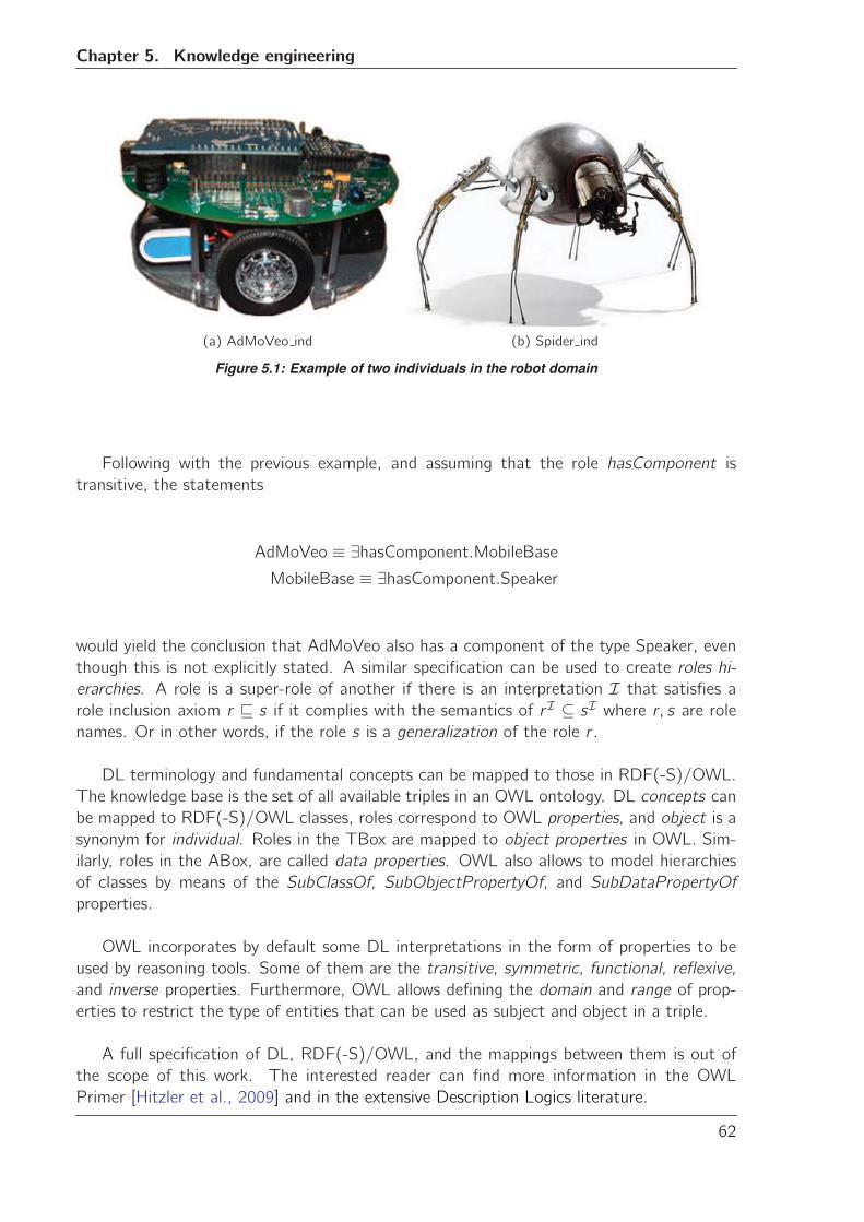
Chapter 5. Knowledge engineering
(a) AdMoVeo ind (b) Spider ind
Figure 5.1: Example of two individuals in the robot domain
Following with the previous example, and assuming that the role hasComponent is
transitive, the statements
AdMoVeo ≡ ∃hasComponent.MobileBaseMobileBase ≡ ∃hasComponent.Speaker
would yield the conclusion that AdMoVeo also has a component of the type Speaker, even
though this is not explicitly stated. A similar specification can be used to create roles hi-
erarchies. A role is a super-role of another if there is an interpretation I that satisfies arole inclusion axiom r � s if it complies with the semantics of rI ⊆ sI where r, s are rolenames. Or in other words, if the role s is a generalization of the role r .
DL terminology and fundamental concepts can be mapped to those in RDF(-S)/OWL.
The knowledge base is the set of all available triples in an OWL ontology. DL concepts can
be mapped to RDF(-S)/OWL classes, roles correspond to OWL properties, and object is a
synonym for individual. Roles in the TBox are mapped to object properties in OWL. Sim-
ilarly, roles in the ABox, are called data properties. OWL also allows to model hierarchies
of classes by means of the SubClassOf, SubObjectPropertyOf, and SubDataPropertyOf
properties.
OWL incorporates by default some DL interpretations in the form of properties to be
used by reasoning tools. Some of them are the transitive, symmetric, functional, reflexive,
and inverse properties. Furthermore, OWL allows defining the domain and range of prop-
erties to restrict the type of entities that can be used as subject and object in a triple.
A full specification of DL, RDF(-S)/OWL, and the mappings between them is out of
the scope of this work. The interested reader can find more information in the OWL
Primer [Hitzler et al., 2009] and in the extensive Description Logics literature.
62
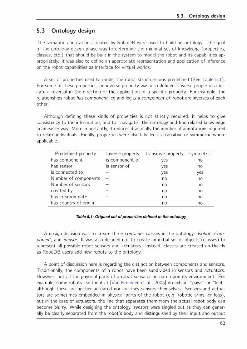
5.3. Ontology design
5.3 Ontology design
The semantic annotations created by RoboDB were used to build an ontology. The goal
of the ontology design phase was to determine the minimal set of knowledge (properties,
classes, etc.) that should be built in the system to model the robot and its capabilities ap-
propriately. It was also to define an appropriate representation and application of inference
on the robot capabilities as interface for virtual worlds.
A set of properties used to model the robot structure was predefined (See Table 5.1).
For some of these properties, an inverse property was also defined. Inverse properties indi-
cate a reversal in the direction of the application of a specific property. For example, the
relationships robot has component leg and leg is a component of robot are inverses of each
other.
Although defining these kinds of properties is not strictly required, it helps to give
consistency to the information, and to “navigate” the ontology and find related knowledge
in an easier way. More importantly, it reduces drastically the number of annotations required
to relate individuals. Finally, properties were also labelled as transitive or symmetric where
applicable.
Predefined property Inverse property transitive property symmetric
has component is component of yes no
has sensor is sensor of yes no
is connected to – yes yes
Number of components – no no
Number of sensors – no no
created by – no no
has creation date – no no
has country of origin – no no
Table 5.1: Original set of properties defined in the ontology
A design decision was to create three container classes in the ontology: Robot, Com-
ponent, and Sensor. It was also decided not to create an initial set of objects (classes) to
represent all possible robot sensors and actuators. Instead, classes are created on-the-fly
as RoboDB users add new robots to the ontology.
A point of discussion here is regarding the distinction between components and sensors.
Traditionally, the components of a robot have been subdivided in sensors and actuators.
However, not all the physical parts of a robot sense or actuate upon its environment. For
example, some robots like the iCat [Van Breemen et al., 2005] do exhibit “paws” or “feet”
although these are neither actuated nor are they sensors themselves. Sensors and actua-
tors are sometimes embedded in physical parts of the robot (e.g. robotic arms, or legs),
but in the case of actuators, the line that separates them from the actual robot body can
become blurry. While designing the ontology, sensors were singled out as they can gener-
ally be clearly separated from the robot’s body and distinguished by their input and output
63
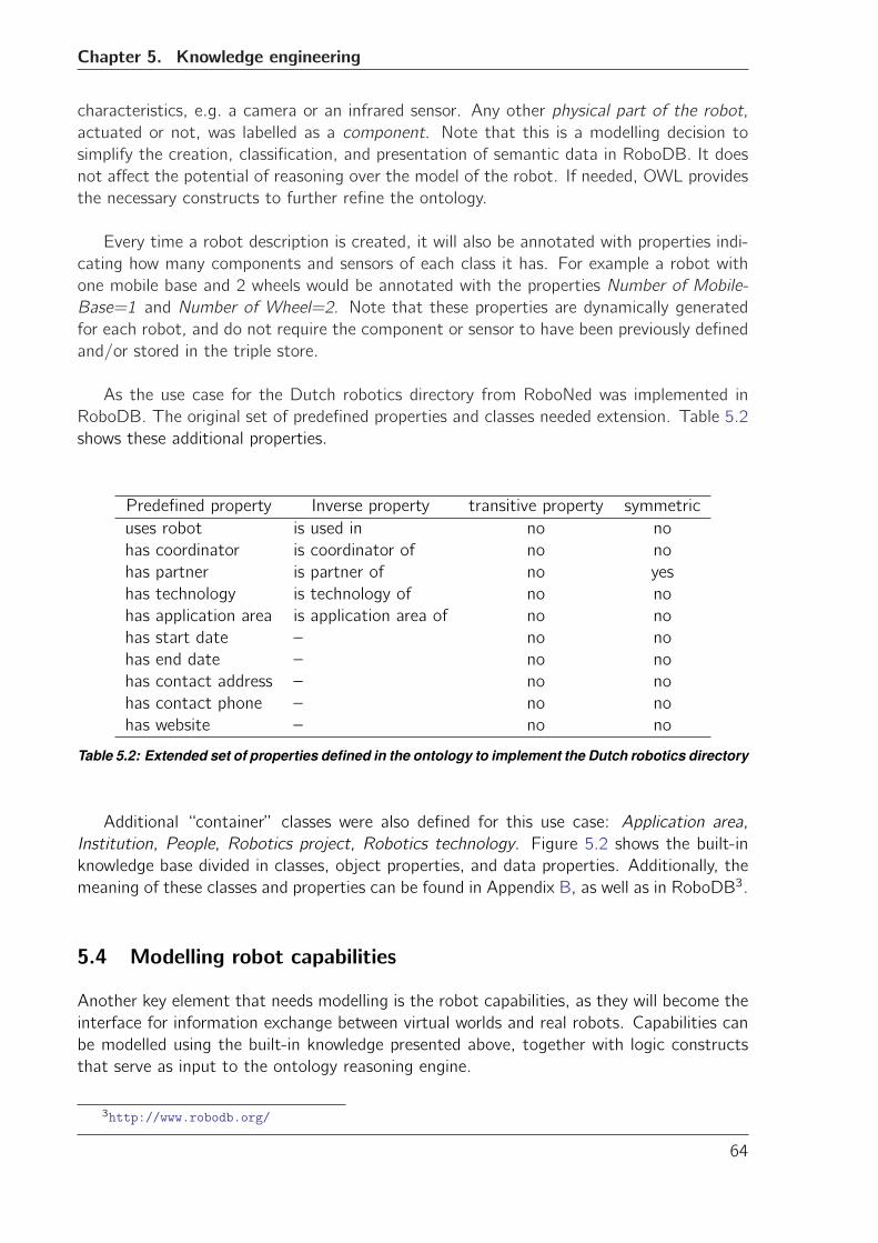
Chapter 5. Knowledge engineering
characteristics, e.g. a camera or an infrared sensor. Any other physical part of the robot,
actuated or not, was labelled as a component. Note that this is a modelling decision to
simplify the creation, classification, and presentation of semantic data in RoboDB. It does
not affect the potential of reasoning over the model of the robot. If needed, OWL provides
the necessary constructs to further refine the ontology.
Every time a robot description is created, it will also be annotated with properties indi-
cating how many components and sensors of each class it has. For example a robot with
one mobile base and 2 wheels would be annotated with the properties Number of Mobile-
Base=1 and Number of Wheel=2. Note that these properties are dynamically generated
for each robot, and do not require the component or sensor to have been previously defined
and/or stored in the triple store.
As the use case for the Dutch robotics directory from RoboNed was implemented in
RoboDB. The original set of predefined properties and classes needed extension. Table 5.2
shows these additional properties.
Predefined property Inverse property transitive property symmetric
uses robot is used in no no
has coordinator is coordinator of no no
has partner is partner of no yes
has technology is technology of no no
has application area is application area of no no
has start date – no no
has end date – no no
has contact address – no no
has contact phone – no no
has website – no no
Table 5.2: Extended set of properties defined in the ontology to implement the Dutch robotics directory
Additional “container” classes were also defined for this use case: Application area,
Institution, People, Robotics project, Robotics technology. Figure 5.2 shows the built-in
knowledge base divided in classes, object properties, and data properties. Additionally, the
meaning of these classes and properties can be found in Appendix B, as well as in RoboDB3.
5.4 Modelling robot capabilities
Another key element that needs modelling is the robot capabilities, as they will become the
interface for information exchange between virtual worlds and real robots. Capabilities can
be modelled using the built-in knowledge presented above, together with logic constructs
that serve as input to the ontology reasoning engine.
3http://www.robodb.org/
64
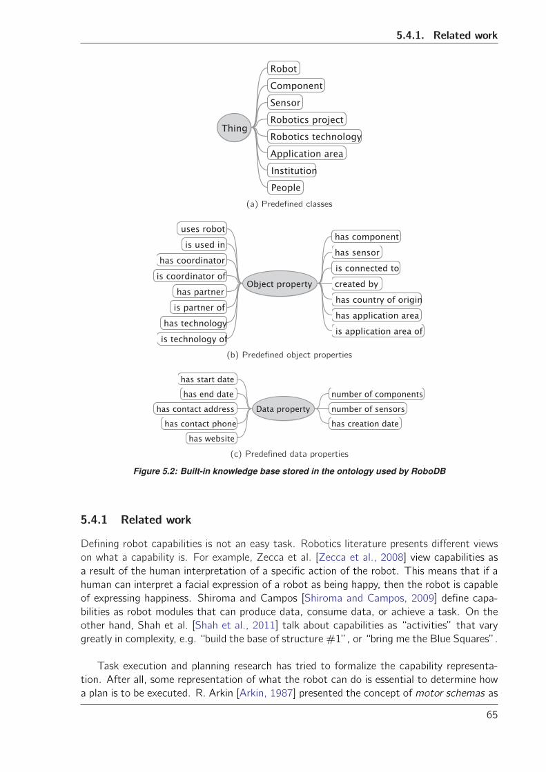
5.4.1. Related work
(a) Predefined classes
(b) Predefined object properties
(c) Predefined data properties
Figure 5.2: Built-in knowledge base stored in the ontology used by RoboDB
5.4.1 Related work
Defining robot capabilities is not an easy task. Robotics literature presents different views
on what a capability is. For example, Zecca et al. [Zecca et al., 2008] view capabilities as
a result of the human interpretation of a specific action of the robot. This means that if a
human can interpret a facial expression of a robot as being happy, then the robot is capable
of expressing happiness. Shiroma and Campos [Shiroma and Campos, 2009] define capa-
bilities as robot modules that can produce data, consume data, or achieve a task. On the
other hand, Shah et al. [Shah et al., 2011] talk about capabilities as “activities” that vary
greatly in complexity, e.g. “build the base of structure #1”, or “bring me the Blue Squares”.
Task execution and planning research has tried to formalize the capability representa-
tion. After all, some representation of what the robot can do is essential to determine how
a plan is to be executed. R. Arkin [Arkin, 1987] presented the concept of motor schemas as
65
Chapter 5. Knowledge engineering
any action or behaviour that the robot exhibits, e.g. avoid an obstacle or find an obstacle.
Theoretically, schemas accommodated several levels of abstraction with sensory schemas
dealing with the low-level input from the robot sensors and the actuator output, and per-
ceptory schemas that worked at a higher level of abstraction to process the information
provided by the sensory schemas. There was no formalism specified for neither perceptory
nor sensory schema implementation in this approach, therefore the schemas were created
ad-hoc for each robot and each situation encountered.
Tang and Parker [Tang and Parker, 2007] introduced a variation of the schema con-
cept in the context of task planning and execution in multi-robot teams. Capabilities were
defined as a set of environmental sensors, perceptual schemas, motor schemas, and com-
munication schemas available to the robot. These schemas are pre-programmed into the
robot at design time. Capabilities are represented as “black-boxes” with labelled inputs
and outputs. These labels are used to match the capabilities of different robots and to
construct a task execution plan.
Robot middleware has also investigated how to represent robot capabilities, with similar
approaches to those in the planning domain. The middleware platform Miro introduced
in [Utz et al., 2002] describes robot capabilities using three layers of abstraction: device
layer, service layer, and class framework layer. The device layer deals directly with the
robot’s sensors and actuators, while the service and class framework deal with the interface
and processing algorithms respectively. The Player middleware presented in [Gerkey et al.,
2001, Gerkey et al., 2003] uses a similar approach by abstracting robot capabilities into
device drivers, and an interface layer that provides an abstract representation of a capability
as a “service” with inputs and outputs to access the low-level device drivers.
Finally, there are few approaches that try to utilize web-service paradigms to describe
common service models and devices. An example is the Service-Oriented Ubiquitous Robotic
Framework (SURF) [Ha et al., 2005] presented in Chapter 2. This approach represents
robot capabilities as web-services using the OWL-S upper ontology to model them. The
following section presents a brief introduction to the fundamentals of OWL-S.
5.4.1.1 OWL-S
The Semantic Markup for Web Services (OWL-S) [Martin et al., 2004] is an upper ontology
to describe web services using OWL. An upper ontology describes general concepts across
knowledge domains, and its main objective is to support semantic interoperability between
ontologies. Upper ontologies are abstract concept definitions designed to ensure consis-
tency and uniqueness of concepts of their implementations. OWL-S provides guidelines
to define web resources with their particular properties and restrictions using three main
abstractions: the service profile, the process model, and the grounding. Figure 5.3 shows
a general view of these three elements.
The service profile provides mechanisms to describe a service by specifying who provides
the service, what function it serves, and what features it offers. Service profiles are crucial
for service discovery as they allow matching service requests with appropriate services of-
fered by providers.
66
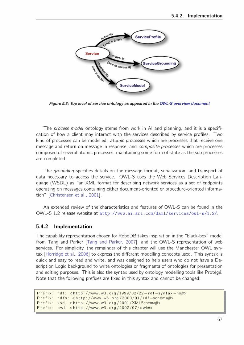
5.4.2. Implementation
Figure 5.3: Top level of service ontology as appeared in the OWL-S overview document
The process model ontology stems from work in AI and planning, and it is a specifi-
cation of how a client may interact with the services described by service profiles. Two
kind of processes can be modelled: atomic processes which are processes that receive one
message and return on message in response, and composite processes which are processes
composed of several atomic processes, maintaining some form of state as the sub processes
are completed.
The grounding specifies details on the message format, serialization, and transport of
data necessary to access the service. OWL-S uses the Web Services Description Lan-
guage (WSDL) as “an XML format for describing network services as a set of endpoints
operating on messages containing either document-oriented or procedure-oriented informa-
tion” [Christensen et al., 2001].
An extended review of the characteristics and features of OWL-S can be found in the
OWL-S 1.2 release website at http://www.ai.sri.com/daml/services/owl-s/1.2/.
5.4.2 Implementation
The capability representation chosen for RoboDB takes inspiration in the “black-box” model
from Tang and Parker [Tang and Parker, 2007], and the OWL-S representation of web
services. For simplicity, the remainder of this chapter will use the Manchester OWL syn-
tax [Horridge et al., 2006] to express the different modelling concepts used. This syntax is
quick and easy to read and write, and was designed to help users who do not have a De-
scription Logic background to write ontologies or fragments of ontologies for presentation
and editing purposes. This is also the syntax used by ontology modelling tools like Protege.
Note that the following prefixes are fixed in this syntax and cannot be changed:
P r e f i x : r d f : <h t t p : //www. w3 . o rg /1999/02/22− r d f−s yn tax−ns#>P r e f i x : r d f s : <h t t p : //www. w3 . o rg /2000/01/ rd f−schema#>P r e f i x : x s d : <h t t p : //www. w3 . o rg /2001/XMLSchema#>
P r e f i x : ow l : <h t t p : //www. w3 . o rg /2002/07/ owl#>
67
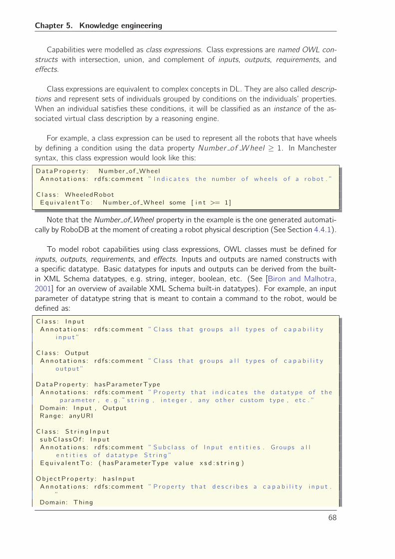
Chapter 5. Knowledge engineering
Capabilities were modelled as class expressions. Class expressions are named OWL con-
structs with intersection, union, and complement of inputs, outputs, requirements, and
effects.
Class expressions are equivalent to complex concepts in DL. They are also called descrip-
tions and represent sets of individuals grouped by conditions on the individuals’ properties.
When an individual satisfies these conditions, it will be classified as an instance of the as-
sociated virtual class description by a reasoning engine.
For example, a class expression can be used to represent all the robots that have wheels
by defining a condition using the data property Number of Wheel ≥ 1. In Manchestersyntax, this class expression would look like this:
DataP r op e r t y : Number of Whee l
A n n o t a t i o n s : r d f s : comment ” I n d i c a t e s the number o f whee l s o f a r obo t . ”
C l a s s : WheeledRobot
Eq u i v a l e n tTo : Number of Whee l some [ i n t >= 1 ]
Note that the Number of Wheel property in the example is the one generated automati-
cally by RoboDB at the moment of creating a robot physical description (See Section 4.4.1).
To model robot capabilities using class expressions, OWL classes must be defined for
inputs, outputs, requirements, and effects. Inputs and outputs are named constructs with
a specific datatype. Basic datatypes for inputs and outputs can be derived from the built-
in XML Schema datatypes, e.g. string, integer, boolean, etc. (See [Biron and Malhotra,
2001] for an overview of available XML Schema built-in datatypes). For example, an input
parameter of datatype string that is meant to contain a command to the robot, would be
defined as:
C l a s s : I n p u t
A n n o t a t i o n s : r d f s : comment ” C l a s s t h a t g roups a l l t y p e s o f c a p a b i l i t y
i n p u t ”
C l a s s : Output
A n n o t a t i o n s : r d f s : comment ” C l a s s t h a t g roups a l l t y p e s o f c a p a b i l i t y
ou tpu t ”
Da t aP r op e r t y : hasParameterType
An n o t a t i o n s : r d f s : comment ” P r op e r t y t h a t i n d i c a t e s the d a t a t y p e o f the
paramete r , e . g . ˜ s t r i n g , i n t e g e r , any o t h e r custom type , e t c . ”
Domain: I npu t , Output
Range: anyURI
C l a s s : S t r i n g I n p u t
s u bC l a s sO f : I n p u t
A n n o t a t i o n s : r d f s : comment ” Su b c l a s s o f I n p u t e n t i t i e s . Groups a l l
e n t i t i e s o f d a t a t y p e S t r i n g ”
Equ i v a l e n tTo : ( hasParameterType v a l u e x s d : s t r i n g )
Ob j e c tP r o p e r t y : h a s I n p u t
A n n o t a t i o n s : r d f s : comment ” P r op e r t y t h a t d e s c r i b e s a c a p a b i l i t y i n p u t .
”
Domain: Thing
68
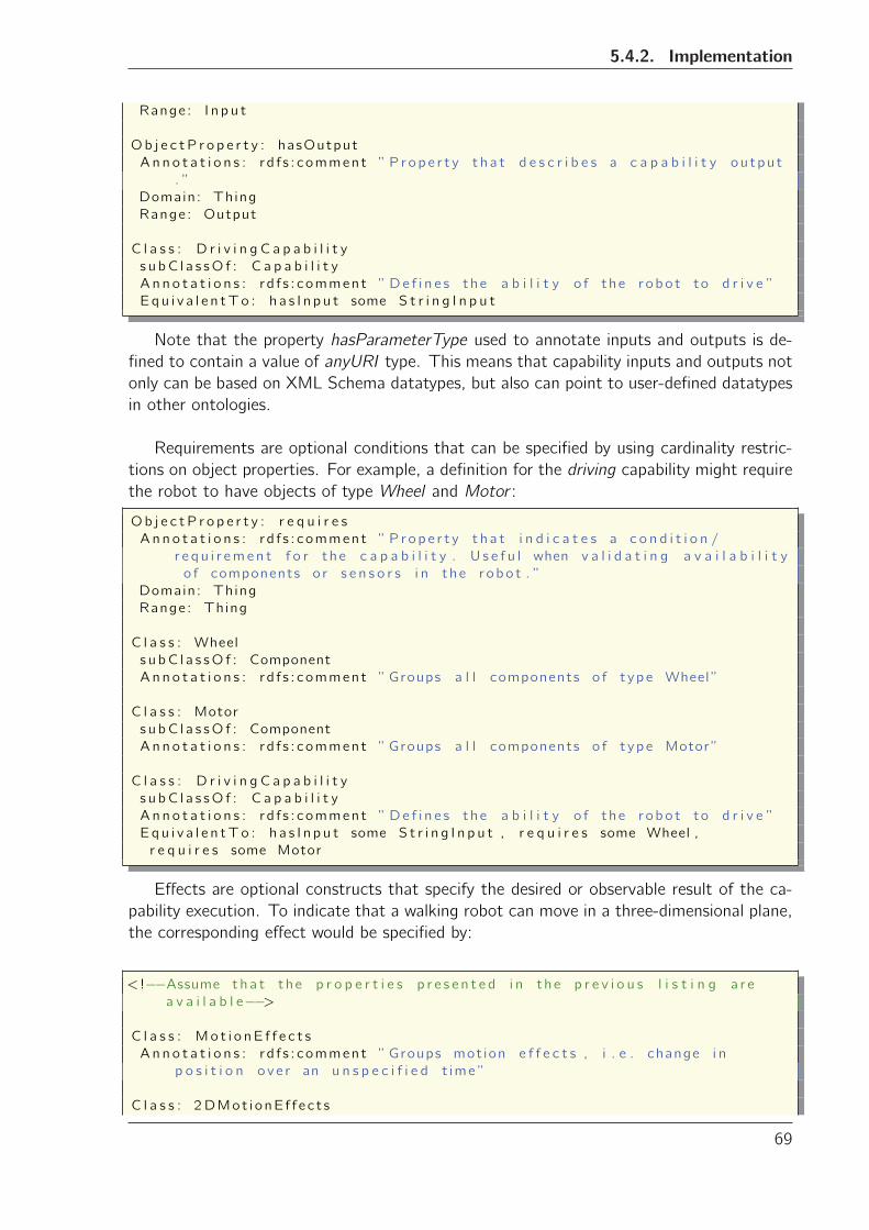
5.4.2. Implementation
Range: I n p u t
Ob j e c t P r o p e r t y : hasOutput
A n n o t a t i o n s : rd f s : comment ” P r op e r t y t h a t d e s c r i b e s a c a p a b i l i t y ou tpu t
. ”
Domain: Thing
Range: Output
C l a s s : D r i v i n g C a p a b i l i t y
s u bC l a s sO f : C a p a b i l i t y
A n n o t a t i o n s : rd f s : comment ” De f i n e s the a b i l i t y o f the r obo t to d r i v e ”
Eq u i v a l e n tTo : h a s I n p u t some S t r i n g I n p u t
Note that the property hasParameterType used to annotate inputs and outputs is de-
fined to contain a value of anyURI type. This means that capability inputs and outputs not
only can be based on XML Schema datatypes, but also can point to user-defined datatypes
in other ontologies.
Requirements are optional conditions that can be specified by using cardinality restric-
tions on object properties. For example, a definition for the driving capability might require
the robot to have objects of type Wheel and Motor :
Ob j e c tP r o p e r t y : r e q u i r e s
A n n o t a t i o n s : rd f s : comment ” P r op e r t y t h a t i n d i c a t e s a c o n d i t i o n /
r e q u i r emen t f o r the c a p a b i l i t y . U s e f u l when v a l i d a t i n g a v a i l a b i l i t y
o f components o r s e n s o r s i n the r obo t . ”
Domain: Thing
Range: Thing
C l a s s : Wheel
s u bC l a s sO f : Component
A n n o t a t i o n s : rd f s : comment ”Groups a l l components o f t ype Wheel ”
C l a s s : Motor
s u bC l a s sO f : Component
A n n o t a t i o n s : rd f s : comment ”Groups a l l components o f t ype Motor”
C l a s s : D r i v i n g C a p a b i l i t y
s u bC l a s sO f : C a p a b i l i t y
A n n o t a t i o n s : rd f s : comment ” De f i n e s the a b i l i t y o f the r obo t to d r i v e ”
Eq u i v a l e n tTo : h a s I n p u t some S t r i n g I n p u t , r e q u i r e s some Wheel ,
r e q u i r e s some Motor
Effects are optional constructs that specify the desired or observable result of the ca-
pability execution. To indicate that a walking robot can move in a three-dimensional plane,
the corresponding effect would be specified by:
< !−−Assume t h a t the p r o p e r t i e s p r e s e n t e d i n the p r e v i o u s l i s t i n g a r e
a v a i l a b l e−−>
C l a s s : Mo t i o nE f f e c t s
A n n o t a t i o n s : rd f s : comment ”Groups mot ion e f f e c t s , i . e . change i n
p o s i t i o n o v e r an u n s p e c i f i e d t ime ”
C l a s s : 2 DMot i onE f f e c t s
69
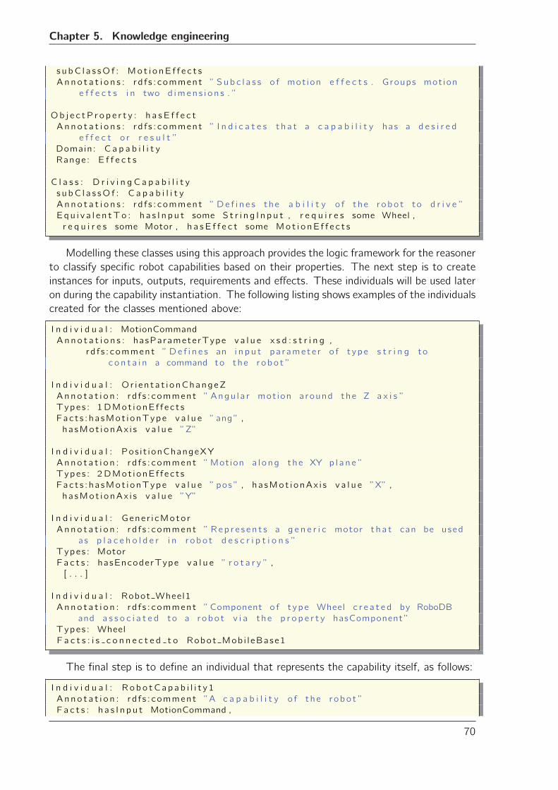
Chapter 5. Knowledge engineering
s u bC l a s sO f : Mo t i o nE f f e c t s
A n n o t a t i o n s : r d f s : comment ” Su b c l a s s o f mot ion e f f e c t s . Groups mot ion
e f f e c t s i n two d imen s i o n s . ”
Ob j e c t P r o p e r t y : h a s E f f e c t
A n n o t a t i o n s : r d f s : comment ” I n d i c a t e s t h a t a c a p a b i l i t y has a d e s i r e d
e f f e c t o r r e s u l t ”
Domain: C a p a b i l i t y
Range: E f f e c t s
C l a s s : D r i v i n g C a p a b i l i t y
s u bC l a s sO f : C a p a b i l i t y
A n n o t a t i o n s : r d f s : comment ” De f i n e s the a b i l i t y o f the r obo t to d r i v e ”
Eq u i v a l e n tTo : h a s I n p u t some S t r i n g I n p u t , r e q u i r e s some Wheel ,
r e q u i r e s some Motor , h a s E f f e c t some Mo t i o nE f f e c t s
Modelling these classes using this approach provides the logic framework for the reasoner
to classify specific robot capabilities based on their properties. The next step is to create
instances for inputs, outputs, requirements and effects. These individuals will be used later
on during the capability instantiation. The following listing shows examples of the individuals
created for the classes mentioned above:
I n d i v i d u a l : MotionCommand
Ann o t a t i o n s : hasParameterType v a l u e x s d : s t r i n g ,
rd f s : comment ” De f i n e s an i n p u t pa ramete r o f t ype s t r i n g to
c o n t a i n a command to the r obo t ”
I n d i v i d u a l : O r i e n t a t i onChangeZ
Anno t a t i o n : rd f s : comment ” Angu l a r mot ion around the Z a x i s ”
Types : 1 DMot i onE f f e c t s
Fac t s : ha sMot i onType v a l u e ”ang” ,
ha sMot i onAx i s v a l u e ”Z”
I n d i v i d u a l : Pos i t ionChangeXY
Anno t a t i o n : rd f s : comment ”Motion a l o ng the XY p l a n e ”
Types : 2 DMot i onE f f e c t s
Fac t s : ha sMot i onType v a l u e ” pos ” , ha sMot i onAx i s v a l u e ”X” ,
ha sMot i onAx i s v a l u e ”Y”
I n d i v i d u a l : Gene r i cMoto r
Anno t a t i o n : rd f s : comment ” Rep r e s e n t s a g e n e r i c motor t h a t can be used
as p l a c e h o l d e r i n r obo t d e s c r i p t i o n s ”
Types : Motor
F a c t s : hasEncoderType v a l u e ” r o t a r y ” ,
[ . . . ]
I n d i v i d u a l : Robot Wheel1
Anno t a t i o n : rd f s : comment ”Component o f t ype Wheel c r e a t e d by RoboDB
and a s s o c i a t e d to a r obo t v i a the p r o p e r t y hasComponent”
Types : Wheel
F a c t s : i s c o n n e c t e d t o Robot Mob i l eBase1
The final step is to define an individual that represents the capability itself, as follows:
I n d i v i d u a l : R o b o tC a p a b i l i t y 1
Anno t a t i o n : rd f s : comment ”A c a p a b i l i t y o f the r obo t ”
F a c t s : h a s I n p u t MotionCommand ,
70
5.4.2.1. Additional restrictions using SWRL
h a s E f f e c t Pos i t ionChangeXY ,
h a s E f f e c t Or i en ta t i onChangeZ ,
r e q u i r e s Robot Wheel1 ,
r e q u i r e s Gene r i cMoto r
It is important to notice that it is not necessary to explicitly state the type of the capa-
bility. It is sufficient to indicate inputs, outputs, effects, and requirements on an individual
and then let an ontology reasoning tool figure out which capability this individual “belongs”
to. In the example presented above, the capability RobotCapability1 would be automatically
classified as a DrivingCapability. This is also true for the individual MotionCommand : the
reasoning tool would classify it as belonging to the class StringInput based on the value of
the property hasParameterType.
In practice, this approach to modelling capabilities has an important consequence: it
allows decoupling the abstract definition of a capability from the individual’s instantiation
in the ontology. This has several benefits: it helps to reuse the capability definitions, to
maintain the consistency of the ontology, and to spot modelling errors, ambiguities, and
similarities in an easier way.
5.4.2.1 Additional restrictions using SWRL
Sometimes it might be desirable to add to the capability definition extra conditions based
on the type of robot that the capability will describe. For example, the definition of Driv-
ingCapability presented above could be further restricted to indicate that it requires that
the robot to which the capability is associated, has at least two wheels.
Unfortunately, the expressive power of OWL is not enough to specify this type of condi-
tion. To understand why, one must recall that properties relate two concepts in triples of the
form subject-predicate-object, where the subject is the individual that is being annotated,
and the object is an individual or value, depending on the property being an ObjectProperty
or DataProperty. In the example above, however, the object is neither an individual nor
a value itself. Instead, it is a condition (i.e. has at least two wheels) that relates to an
external entity (i.e. the robot).
To express this type of relationships, one must combine OWL class expressions with
Semantic Web Rules (SWRL) [Horrocks and Patel-Schneider, 2004]. SWRL is a combina-
tion of OWL constructs and the RuleML sublanguage [Boley et al., 2001]. SWRL extends
OWL by providing an abstract syntax based on Horn-like clauses to create rules. These rules
follow the structure of implications between antecedent and consequent logic expressions.
Moreover, SWRL provides a set of built-in expressions designed to perform comparisons,
mathematical operations, string manipulation, date, time, and duration specification.
A rule in SWRL is specified as an implication of the form antecedent =⇒ consequent.The antecedent and consequent consist of sets of atoms. Atoms are combinations (con-
junctions) of classes, properties, equality statements (sameAs), inequality statements (dif-
ferentFrom), and built-in functions. For example, a rule stating that a robot with at least
one wheel belongs to the class of WheeledRobots, could be written like this
71
Chapter 5. Knowledge engineering
Robot (? r ) , Number of Whee l (? r , ? v a l u e ) , g r e a t e rThan (? va l u e , 0 ) −>WheeledRobot (? r )
This rule can be read as “If there exists a robot and this robot is annotated with the
property Number of Wheel, with a value greater than 0, then it is a wheeled robot”.
Robot capabilities can then be modelled in two ways: by specializing an existing class
definition, or by replacing the class definition by its SWRL equivalent. For example, using
the first method, the definition of DrivingCapability can be extended to require the presence
of at least two wheels as follows
C l a s s : D r i v i n g C a p a b i l i t y
s u bC l a s sO f : C a p a b i l i t y
A n n o t a t i o n s : r d f s : comment ” De f i n e s the a b i l i t y o f the r obo t to d r i v e ”
Equ i v a l e n tTo : ( r e q u i r e s some Wheel ) and ( h a s E f f e c t some 2
DMot i onE f f e c t s )
Da t aP r op e r t y : robotHasMinNumberOfWheel
Domain: C a p a b i l i t y
Range: i n t e g e r
< !−− SWRL r u l e d e f i n i t i o n−−>Robot (? r obo t ) , D r i v i n g C a p a b i l i t y (? cap ) , h a s C a p a b i l i t y (? robot , ? cap ) ,
Number of Whee l (? robot , ? v a l u e ) −> robotHasMinNumberOfWheel (? cap , ?
v a l u e )
< !−− S p e c i a l i z e d c l a s s d e f i n i t i o n −−>C l a s s TwoWhee l e dRobo tD r i v i n gCapab i l i t y
s u bC l a s sO f : D r i v i n g C a p a b i l i t y
A n n o t a t i o n s : r d f s : comment ” S p e c i a l i z e d v e r s i o n o f D r i v i n g C a p a b i l i t y
t h a t r e q u i r e s the p r e s e n c e o f a t l e a s t two whee l s i n the r obo t ”
Equ i v a l e n tTo : robotHasMinNumberOfWheel some i n t [>=2]
Defining the DrivingCapability class purely in SWRL involves translating the class ex-
pression into its SWRL equivalent. For the example above, the capability representation is
as follows:
C l a s s : D r i v i n g C a p a b i l i t y
s u bC l a s sO f : C a p a b i l i t y
A n n o t a t i o n s : r d f s : comment ” De f i n e s the a b i l i t y o f the r obo t to d r i v e ”
< !−− SWRL r u l e d e f i n i n g the d r i v i n g c a p a b i l i t y −−>Mot i o nE f f e c t s (? motE f f e c t ) , I n p u t (? s I n p u t ) , Wheel (? comp1 ) , Motor (? comp2 )
, Robot (? r obo t ) , h a s E f f e c t (? cap , ? motE f f e c t ) , h a s C a p a b i l i t y (? robot ,
? cap ) , h a s I n p u t (? cap , ? s I n p u t ) , r e q u i r e s (? cap , ?comp1 ) , r e q u i r e s (?
cap , ?comp2 ) , Number of Whee l (? robot , ? v a l u e ) , g r e a t e rThan (? va l u e ,
1) −> D r i v i n g C a p a b i l i t y (? cap )
It might be tempting to think that the best solution to represent a robot capability is to
encode it directly in SWRL rules, as this would avoid the specification of class expressions
and the combination of two encoding syntaxes (OWL and SWRL). However, it is a good
practice to use OWL as much as possible due to two factors:
• SWRL rules can lead to undecidability. As shown previously, OWL and especially itssubset OWL-DL, guard a close relationship with DL and therefore, it maintains most
72
5.4.3. Using the robot capability descriptions
of its decidability properties. Decidability is important for an ontology tool to be able
to classify i.e. perform inference over an ontology. It was shown by Horrocks and
Schneider [Horrocks and Patel-Schneider, 2004] that the inclusion of rules in OWL
could lead to undecidability. Although this is alleviated by reasoners implementation of
“DL-safe” SWRL rules, this means that inferences are restricted to named individuals
in the ontology.
• SWRL is not a standard. This means that rule inference implementation and perfor-mance depend on the reasoning engine used. It is also generally accepted that the
inclusion of SWRL rules has an impact on the performance of the reasoner. Zhang
and Miller [Zhang and Miller, 2005] showed that the query performance of a SWRL
based reasoning tool is indeed decreased -albeit slightly- with respect to an RDF(-
S)/OWL reasoner, and there are indications that this is also true for the inference
process.
5.4.3 Using the robot capability descriptions
The ontology modelled using the approach described above can be used to answer queries
about the robot capabilities. One way of constructing queries is using class expressions in
a similar way as shown before. For example, a query to retrieve all robots that can walk,
could be defined by the expression:
C l a s s : CanWalk
s u bC l a s sO f : Que r i e s
E q u i v a l e n tTo : h a s C a p a b i l i t y some Wa l k i n gC a p a b i l i t y
More complex queries can be built upon existing ones, by applying the same principle.
For example, a query the ontology for all robots that can play a ball game looks like this:
C l a s s : CanMove
Ann o t a t i o n s : rd f s : comment ” Que r i e s the o n t o l o g y f o r r o b o t s t h a t can
move”
s u bC l a s sO f : Que r i e s
E q u i v a l e n tTo : CanWalk o r CanDr i ve
C l a s s : CanK ickABa l l
A n n o t a t i o n s : rd f s : comment ” Que r i e s the o n t o l o g y f o r r o b o t s t h a t can
k i c k b a l l s ”
s u bC l a s sO f : Que r i e s
E q u i v a l e n tTo : h a s C a p a b i l i t y some B a l l S h o o t i n g C a p a b i l i t y
[ . . . ]
C l a s s : CanPlayBa l lGame
Ann o t a t i o n s : rd f s : comment ” Que r i e s the o n t o l o g y f o r r o b o t s t h a t can
p l a y a w i t h b a l l s by k i c k i n g them”
s u bC l a s sO f : Que r i e s
E q u i v a l e n tTo : CanMove and CanK ickABa l l
Another useful tool to query ontologies from third-party applications is the SPARQL
query language for RDF [Prud’Hommeaux and Seaborne, 2008]. SPARQL provides access
to RDF data using a triple pattern called the basic graph pattern. Users familiar with
database query languages like SQL will find similarities with the SPARQL syntax model.
SPARQL can be combined with the queries presented before to produce a query asking for
all robots that can walk like this:
73
Chapter 5. Knowledge engineering
PREFIX r d f : <h t t p : //www. w3 . o rg /1999/02/22− r d f−s yn tax−ns#>PREFIX r d f s : <h t t p : //www. w3 . o rg /2000/01/ rd f−schema#>PREFIX x s d : <h t t p : //www. w3 . o rg /2001/XMLSchema#>
PREFIX f n : <h t t p : //www. w3 . o rg /2005/ xpath− f u n c t i o n s#>PREFIX r d b : <h t t p : //www. robodb . o rg / o n t o l o g i e s / r o b o t o n t o l o g y#>
SELECT ? robo t
FROM < r o b o t o n t o l o g y . r d f>
WHERE {? r obo t r d f : t y p e rdb:CanWalk .
}
Note that SPARQL is designed to work over RDF graphs. Therefore, an ontology
encoded using OWL must be transformed into its RDF representation before it can be
queried. This feature is usually available in triple stores that provide a web-service endpoint
that supports the SPARQL query protocol.
5.5 Case study: ROILAbot
In order to test the use of semantic descriptions of a robot’s structure and capabilities, a
case study based on the ROILAbot capabilities was developed. ROILAbot is a mobile robot
created by O. Mubin [Mubin, 2011] to showcase the Robot Interaction Language (ROILA).
ROILA is intended to be a new, possibly more effective way for humans to communicate
with their robots. ROILAbot is built with Lego Mindstorm NXT (See Figure 5.4a).
ROILAbot can do several things. Although it can only understand ROILA, if the ap-
propriate command is given, it can move forward and backward, rotate left and right, and
even shoot a ball. The objective of the case study was to model these capabilities using the
approach presented above, and use this model as a bridge that enable virtual world users to
communicate with the real robot from within a virtual world.
The virtual world chosen for the case study was Second Life. Within Second Life users
can easily create virtual artefacts and scripts to add functionality to them. Interaction with
virtual objects and avatars in Second Life is done either by using the chat interface, or by
“touching” the objects in question with a left-click of the mouse.
The technical setup of the virtual world for the case study included a local web server
(Apache server) running the OpenSim simulation engine [OpenSim, 2011]. OpenSim is an
open source, multi-platform and multi-user 3D application server that provides the physical
simulation necessary to create a virtual world. This virtual world is accessed and modified
using the Second Life viewer application. This application offers script creation for virtual
agents, and communication from/to the virtual world.
A virtual version of ROILAbot with the same functionality of the real robot was cre-
ated in Second Life. This had a dual purpose: on the one hand, the virtual robot would
serve as the interface for virtual world users to interact with the real robot, on the other
hand, virtual world users can practice the ROILA commands to control the virtual robot in
the virtual world, before they start sending them to the real robot. Figure 5.4b shows a
74
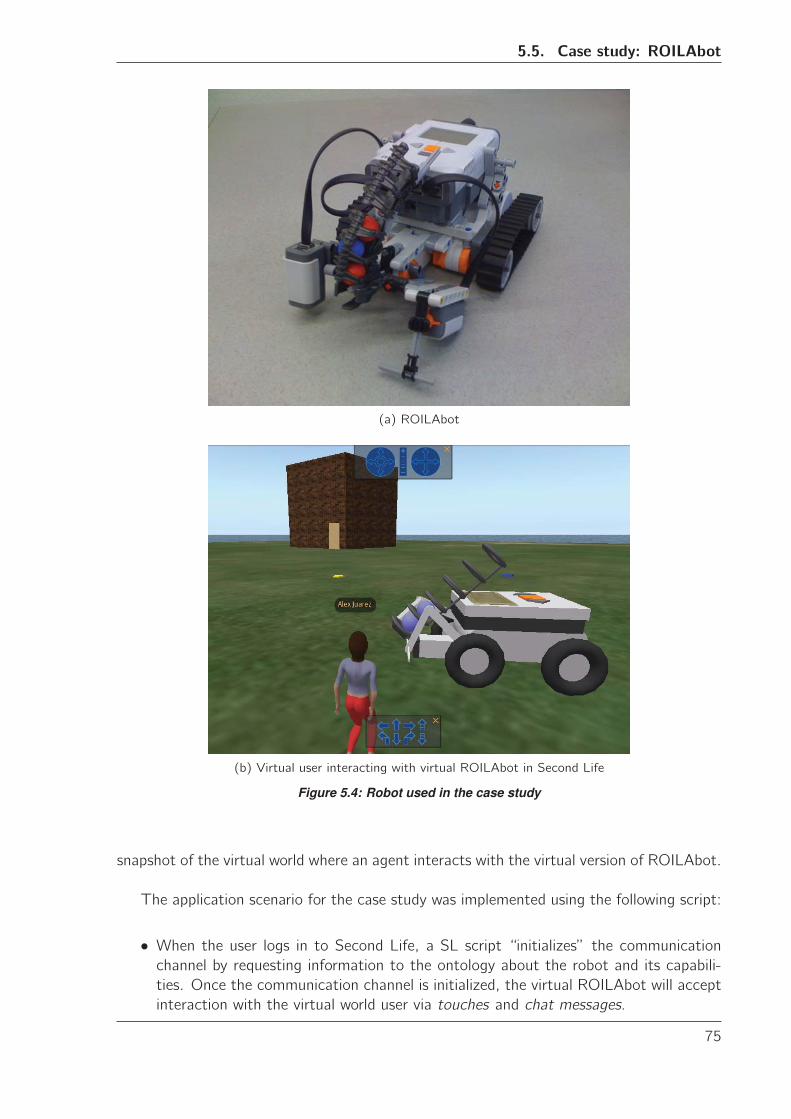
5.5. Case study: ROILAbot
(a) ROILAbot
(b) Virtual user interacting with virtual ROILAbot in Second Life
Figure 5.4: Robot used in the case study
snapshot of the virtual world where an agent interacts with the virtual version of ROILAbot.
The application scenario for the case study was implemented using the following script:
• When the user logs in to Second Life, a SL script “initializes” the communicationchannel by requesting information to the ontology about the robot and its capabili-
ties. Once the communication channel is initialized, the virtual ROILAbot will accept
interaction with the virtual world user via touches and chat messages.
75
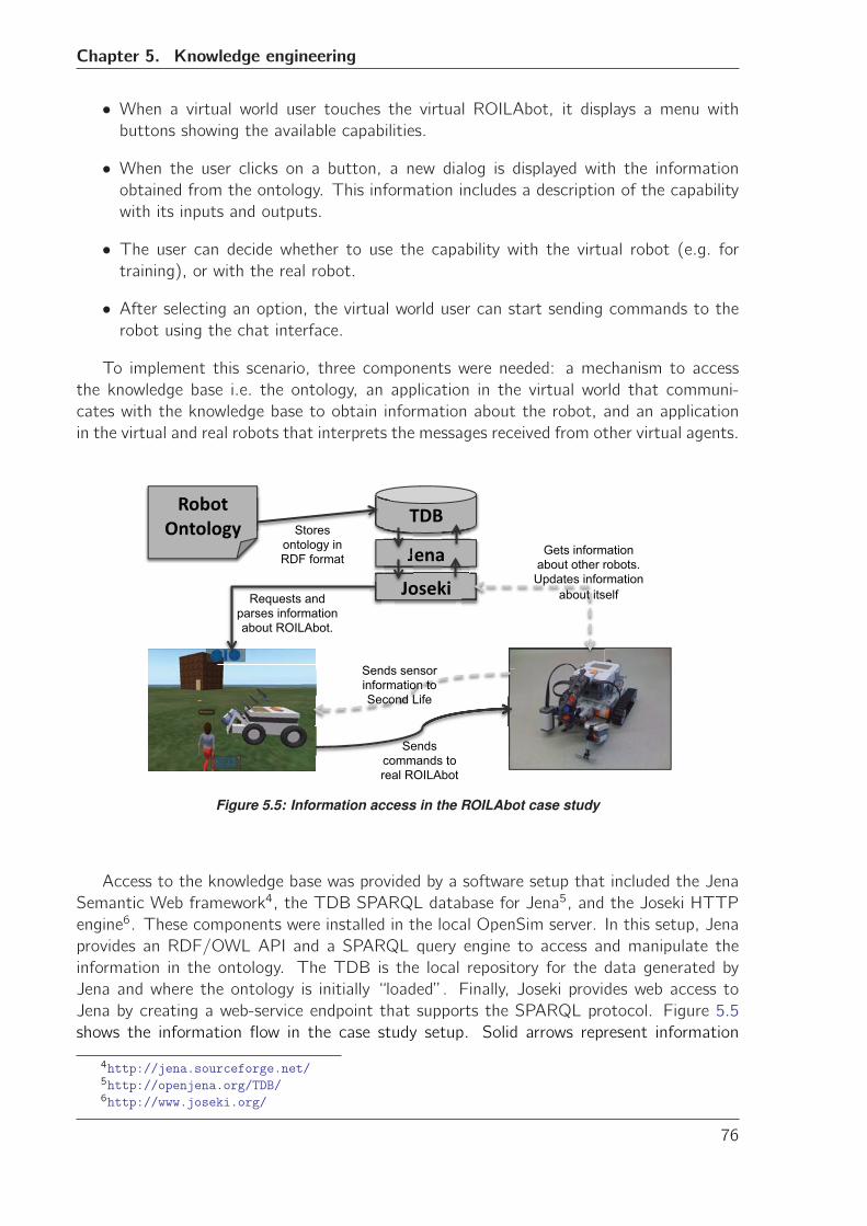
Chapter 5. Knowledge engineering
• When a virtual world user touches the virtual ROILAbot, it displays a menu withbuttons showing the available capabilities.
• When the user clicks on a button, a new dialog is displayed with the informationobtained from the ontology. This information includes a description of the capability
with its inputs and outputs.
• The user can decide whether to use the capability with the virtual robot (e.g. fortraining), or with the real robot.
• After selecting an option, the virtual world user can start sending commands to therobot using the chat interface.
To implement this scenario, three components were needed: a mechanism to access
the knowledge base i.e. the ontology, an application in the virtual world that communi-
cates with the knowledge base to obtain information about the robot, and an application
in the virtual and real robots that interprets the messages received from other virtual agents.
� ����
���
����
����� ��
Sends commands to real ROILAbot
Sends sensor information to Second Life
Gets information about other robots. Updates information
about itself Requests and parses information about ROILAbot.
Stores ontology in RDF format �
�
�
��
�
�
Figure 5.5: Information access in the ROILAbot case study
Access to the knowledge base was provided by a software setup that included the Jena
Semantic Web framework4, the TDB SPARQL database for Jena5, and the Joseki HTTP
engine6. These components were installed in the local OpenSim server. In this setup, Jena
provides an RDF/OWL API and a SPARQL query engine to access and manipulate the
information in the ontology. The TDB is the local repository for the data generated by
Jena and where the ontology is initially “loaded”. Finally, Joseki provides web access to
Jena by creating a web-service endpoint that supports the SPARQL protocol. Figure 5.5
shows the information flow in the case study setup. Solid arrows represent information
4http://jena.sourceforge.net/5http://openjena.org/TDB/6http://www.joseki.org/
76
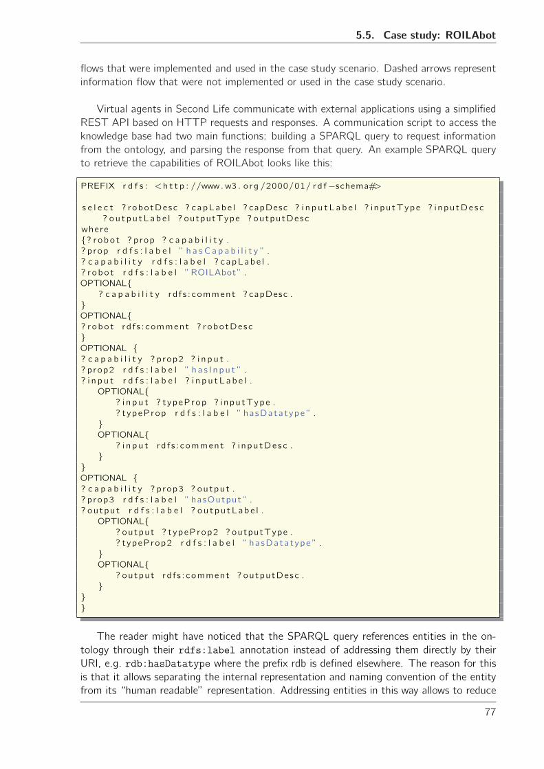
5.5. Case study: ROILAbot
flows that were implemented and used in the case study scenario. Dashed arrows represent
information flow that were not implemented or used in the case study scenario.
Virtual agents in Second Life communicate with external applications using a simplified
REST API based on HTTP requests and responses. A communication script to access the
knowledge base had two main functions: building a SPARQL query to request information
from the ontology, and parsing the response from that query. An example SPARQL query
to retrieve the capabilities of ROILAbot looks like this:
PREFIX r d f s : <h t t p : //www. w3 . o rg /2000/01/ rd f−schema#>
s e l e c t ? robotDesc ? capLabe l ? capDesc ? i n p u t L a b e l ? i npu tType ? i npu tDe s c
? ou t p u tL ab e l ? outputType ? outputDesc
where
{? r obo t ? prop ? c a p a b i l i t y .? prop r d f s : l a b e l ” h a s C a p a b i l i t y ” .
? c a p a b i l i t y r d f s : l a b e l ? c apLabe l .
? r obo t r d f s : l a b e l ”ROILAbot” .
OPTIONAL{? c a p a b i l i t y rd f s : comment ? capDesc .
}OPTIONAL{? r obo t rd f s : comment ? robotDesc
}OPTIONAL {? c a p a b i l i t y ? prop2 ? i n p u t .
? prop2 r d f s : l a b e l ” h a s I n p u t ” .
? i n p u t r d f s : l a b e l ? i n p u t L a b e l .
OPTIONAL{? i n p u t ? typeProp ? i npu tType .
? typeProp r d f s : l a b e l ” hasData type ” .
}OPTIONAL{
? i n p u t rd f s : comment ? i npu tDe s c .
}}OPTIONAL {? c a p a b i l i t y ? prop3 ? ou tpu t .
? prop3 r d f s : l a b e l ” hasOutput ” .
? ou tpu t r d f s : l a b e l ? o u t p u tL ab e l .
OPTIONAL{? output ? typeProp2 ? outputType .
? typeProp2 r d f s : l a b e l ” hasData type ” .
}OPTIONAL{
? outpu t rd f s : comment ? outputDesc .
}}}
The reader might have noticed that the SPARQL query references entities in the on-
tology through their rdfs:label annotation instead of addressing them directly by their
URI, e.g. rdb:hasDatatype where the prefix rdb is defined elsewhere. The reason for this
is that it allows separating the internal representation and naming convention of the entity
from its “human readable” representation. Addressing entities in this way allows to reduce
77
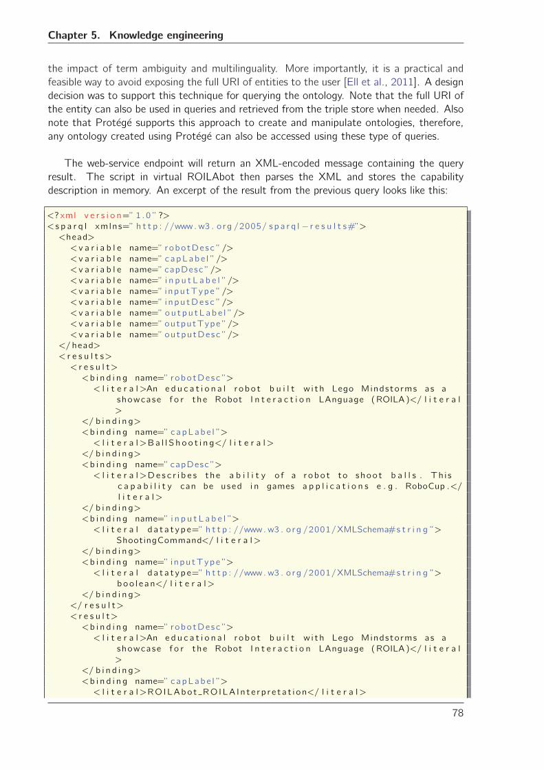
Chapter 5. Knowledge engineering
the impact of term ambiguity and multilinguality. More importantly, it is a practical and
feasible way to avoid exposing the full URI of entities to the user [Ell et al., 2011]. A design
decision was to support this technique for querying the ontology. Note that the full URI of
the entity can also be used in queries and retrieved from the triple store when needed. Also
note that Protege supports this approach to create and manipulate ontologies, therefore,
any ontology created using Protege can also be accessed using these type of queries.
The web-service endpoint will return an XML-encoded message containing the query
result. The script in virtual ROILAbot then parses the XML and stores the capability
description in memory. An excerpt of the result from the previous query looks like this:
<? xml v e r s i o n=” 1 .0 ”?>
< s p a r q l xmlns=” h t t p : //www. w3 . o rg /2005/ s p a r q l − r e s u l t s#”><head>
< v a r i a b l e name=” robotDesc ”/>
< v a r i a b l e name=” capLabe l ”/>
< v a r i a b l e name=”capDesc ”/>
< v a r i a b l e name=” i n p u t L a b e l ”/>
< v a r i a b l e name=” inpu tType ”/>
< v a r i a b l e name=” i npu tDe s c ”/>
< v a r i a b l e name=” ou t p u tL ab e l ”/>
< v a r i a b l e name=” outputType ”/>
< v a r i a b l e name=” outputDesc ”/>
</ head>
< r e s u l t s>
< r e s u l t>
<b i n d i n g name=” robotDesc ”>
< l i t e r a l>An e d u c a t i o n a l r obo t b u i l t w i t h Lego Mindstorms as a
showcase f o r the Robot I n t e r a c t i o n LAnguage (ROILA)</ l i t e r a l
>
</ b i n d i n g>
<b i n d i n g name=” capLabe l ”>
< l i t e r a l>Ba l l S h o o t i n g</ l i t e r a l>
</ b i n d i n g>
<b i n d i n g name=”capDesc ”>
< l i t e r a l>De s c r i b e s the a b i l i t y o f a r obo t to shoo t b a l l s . Th i s
c a p a b i l i t y can be used i n games a p p l i c a t i o n s e . g . RoboCup .</
l i t e r a l>
</ b i n d i n g>
<b i n d i n g name=” i n p u t L a b e l ”>
< l i t e r a l d a t a t y p e=” h t t p : //www. w3 . o rg /2001/XMLSchema#s t r i n g ”>
ShootingCommand</ l i t e r a l>
</ b i n d i n g>
<b i n d i n g name=” inpu tType ”>
< l i t e r a l d a t a t y p e=” h t t p : //www. w3 . o rg /2001/XMLSchema#s t r i n g ”>
boo l e an</ l i t e r a l>
</ b i n d i n g>
</ r e s u l t>
< r e s u l t>
<b i n d i n g name=” robotDesc ”>
< l i t e r a l>An e d u c a t i o n a l r obo t b u i l t w i t h Lego Mindstorms as a
showcase f o r the Robot I n t e r a c t i o n LAnguage (ROILA)</ l i t e r a l
>
</ b i n d i n g>
<b i n d i n g name=” capLabe l ”>
< l i t e r a l>ROILAbo t ROILA In t e r p r e t a t i on</ l i t e r a l>
78
5.5. Case study: ROILAbot
</ b i n d i n g>
<b i n d i n g name=”capDesc ”>
< l i t e r a l>De s c r i b e s the a b i l i t y o f the r obo t to speak Robot
I n t e r a c t i o n LAnguage (ROILA)</ l i t e r a l>
</ b i n d i n g>
<b i n d i n g name=” i n p u t L a b e l ”>
< l i t e r a l>ROILALanguageSt r i ng Input</ l i t e r a l>
</ b i n d i n g>
<b i n d i n g name=” inpu tType ”>
< l i t e r a l d a t a t y p e=” h t t p : //www. w3 . o rg /2001/XMLSchema#s t r i n g ”>
s t r i n g</ l i t e r a l>
</ b i n d i n g>
<b i n d i n g name=” i npu tDe s c ”>
< l i t e r a l>Re f e r s o f an i n p u t pa ramete r o f t ype s t r i n g c o n t a i n i n g
ROILA s e n t e n c e s .</ l i t e r a l>
</ b i n d i n g>
<b i n d i n g name=” ou t p u tL ab e l ”>
< l i t e r a l>ROILALanguageStr ingOutput</ l i t e r a l>
</ b i n d i n g>
<b i n d i n g name=” outputType ”>
< l i t e r a l d a t a t y p e=” h t t p : //www. w3 . o rg /2001/XMLSchema#s t r i n g ”>
s t r i n g</ l i t e r a l>
</ b i n d i n g>
<b i n d i n g name=” outputDesc ”>
< l i t e r a l>An outpu t pa ramete r o f t ype s t r i n g c o n t a i n i n g ROILA
s e n t e n c e s .</ l i t e r a l>
</ b i n d i n g>
</ r e s u l t>
[ . . . ]
</ r e s u l t s>
</ s p a r q l>
The interpretation of this XML format is straightforward. The head section contains the
variable names used in the SPARQL query. The results section contains the different bind-
ings found by the inference engine for those variables. In an analogy to relational databases
terminology, the variable elements are akin to column names, while each result element
is akin to a row in a query resultset. Note that the OPTIONAL keyword in a SPARQL query
causes that a variable for which no binding was found is not included in the correspond-
ing result element, resulting in some of them to show fewer bindings than the defined
variables. More information on the SPARQL Query Results XML format can be found at
http://www.w3.org/TR/rdf-sparql-XMLres/.
Once the results have been parsed, the virtual world user can interact with the virtual
ROILAbot by touching it. This will bring a series of dialogs that allow first to select a
capability (Figure 5.6a), and then to get detailed information about it and start using it
with either the virtual or the real robot (Figure 5.6b).
After a capability has been selected, transmitting an actual message to either the virtual
or the real ROILAbot is done by encoding and sending it in an XML format. An example
of a message requesting the robot to shoot a ball looks like this:
79
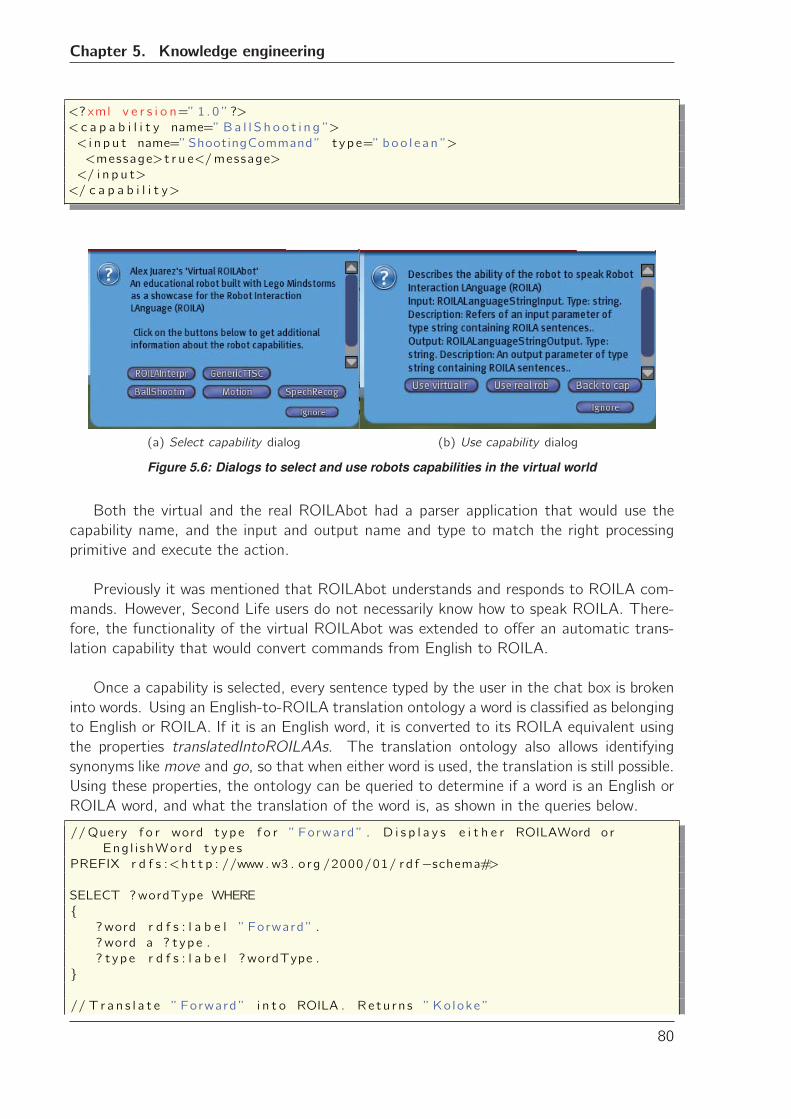
Chapter 5. Knowledge engineering
<? xml v e r s i o n=” 1 .0 ”?>
< c a p a b i l i t y name=” Ba l l S h o o t i n g ”>
< i n p u t name=”ShootingCommand” t ype=” boo l e an ”>
<message>t r u e</message>
</ i n p u t>
</ c a p a b i l i t y>
(a) Select capability dialog (b) Use capability dialog
Figure 5.6: Dialogs to select and use robots capabilities in the virtual world
Both the virtual and the real ROILAbot had a parser application that would use the
capability name, and the input and output name and type to match the right processing
primitive and execute the action.
Previously it was mentioned that ROILAbot understands and responds to ROILA com-
mands. However, Second Life users do not necessarily know how to speak ROILA. There-
fore, the functionality of the virtual ROILAbot was extended to offer an automatic trans-
lation capability that would convert commands from English to ROILA.
Once a capability is selected, every sentence typed by the user in the chat box is broken
into words. Using an English-to-ROILA translation ontology a word is classified as belonging
to English or ROILA. If it is an English word, it is converted to its ROILA equivalent using
the properties translatedIntoROILAAs. The translation ontology also allows identifying
synonyms like move and go, so that when either word is used, the translation is still possible.
Using these properties, the ontology can be queried to determine if a word is an English or
ROILA word, and what the translation of the word is, as shown in the queries below.
//Query f o r word t ype f o r ” Forward ” . D i s p l a y s e i t h e r ROILAWord or
Eng l i shWord t y p e s
PREFIX r d f s :<h t t p : //www. w3 . o rg /2000/01/ rd f−schema#>
SELECT ?wordType WHERE
{?word r d f s : l a b e l ” Forward ” .
?word a ? t ype .
? t ype r d f s : l a b e l ?wordType .
}
// T r a n s l a t e ” Forward ” i n t o ROILA . Re tu rn s ”Ko loke ”
80
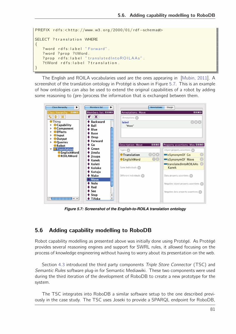
5.6. Adding capability modelling to RoboDB
PREFIX r d f s :<h t t p : //www. w3 . o rg /2000/01/ rd f−schema#>
SELECT ? t r a n s l a t i o n WHERE
{?word r d f s : l a b e l ” Forward ” .
?word ? prop ? tWord .
? prop r d f s : l a b e l ” t r a n s l a t e d I n t oRO ILAAs ” .
? tWord r d f s : l a b e l ? t r a n s l a t i o n .
}
The English and ROILA vocabularies used are the ones appearing in [Mubin, 2011]. A
screenshot of the translation ontology in Protege is shown in Figure 5.7. This is an example
of how ontologies can also be used to extend the original capabilities of a robot by adding
some reasoning to (pre-)process the information that is exchanged between them.
Figure 5.7: Screenshot of the English-to-ROILA translation ontology
5.6 Adding capability modelling to RoboDB
Robot capability modelling as presented above was initially done using Protege. As Protege
provides several reasoning engines and support for SWRL rules, it allowed focusing on the
process of knowledge engineering without having to worry about its presentation on the web.
Section 4.3 introduced the third party components Triple Store Connector (TSC) and
Semantic Rules software plug-in for Semantic Mediawiki. These two components were used
during the third iteration of the development of RoboDB to create a new prototype for the
system.
The TSC integrates into RoboDB a similar software setup to the one described previ-
ously in the case study. The TSC uses Joseki to provide a SPARQL endpoint for RoboDB,
81
Chapter 5. Knowledge engineering
and the Jena framework to provide access to the triple store. However, a relational MySQL
database was used instead of the TDB storage component. The reason for this change
was practical: MySQL databases are easier to setup and maintain than a custom TDB
storage. Every change in the semantic annotations in RoboDB triggers the corresponding
modification in the TSC, keeping the semantic information in RoboDB and in the triple
store synchronized. When the TSC receives a request for information, it also returns an
XML-encoded string.
The Semantic Rules extension provides a basic interface to add rules to the triple store.
These rules have the same semantics as SWRL rules, however, their syntax is based in
Frame Logic (F-Logic) [Kifer and Lausen, 1989]. The Semantic Rules extension allows
to create two kinds of rules: definition rules and calculation rules. With these rules, it is
possible to define class expressions and restrictions as shown in Section 5.4.2.1. Figure 5.8
shows screenshots of the modelling of the DrivingCapability in the RoboDB prototype: Fig-
ure 5.8a shows the user interface of the rule extension that allows to define rules based in
conjunctions of triples, Figure 5.8b shows the resulting capability definition in the F-Logic
language syntax, and Figure 5.8c shows the same capability defined in Protege.
Although no exhaustive usability evaluation was performed over the new RoboDB pro-
totype that includes the robot capability modelling, a small group of three stakeholders
from the robotics community were consulted about their impression on the new feature.
Their responses were mixed. On the positive side, they indicated that they “got the point
of creating rules”, and that they “understood how rules were created and how they could
be used”. On the negative side, they stated that “ it just takes too much time” and that
“it seems that [they] should know a lot about rules and logic modelling to create sensible
statements”. These reactions are similar to the ones initially received for the process of
creating description of a robot’s physical structure. This is an indicator that a streamlining
and redesign of the process may help to improve the perception of the capability definition,
the same way it did with the robot’s physical description process.
5.7 Concluding remarks
This chapter presented the knowledge engineering process to model robot capabilities using
OWL constructs and the information about the robot. It also showed how complex capabil-
ities can be modelled by combining OWL class expressions with SWRL rules. It presented a
case study to demonstrate that the semantic information created using this approach can
be used to enable interoperability between virtual world users and the ROILAbot. Finally, it
showed a possibility to integrate this approach into RoboDB. However, this approach also
has its limitations.
Section 5.4.2.1 hinted at the limitations of using SWRL rules to describe robot capa-
bilities. OWL in itself also imposes some limitations besides the open world assumption.
For example, OWL DL cannot express fuzzy statements like “robots often have wheels”,
and it is equally easy to create incorrect/false monotonic definitions and inferences like ”all
robots that have legs can walk, iCat has legs, therefore iCat can walk” which is not true as
the iCat robot has ”legs” (paws) that are not actuated.
82
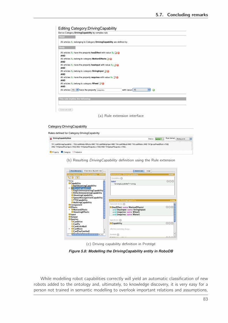
5.7. Concluding remarks
(a) Rule extension interface
(b) Resulting DrivingCapability definition using the Rule extension
(c) Driving capability definition in Protege
Figure 5.8: Modelling the DrivingCapability entity in RoboDB
While modelling robot capabilities correctly will yield an automatic classification of new
robots added to the ontology and, ultimately, to knowledge discovery, it is very easy for a
person not trained in semantic modelling to overlook important relations and assumptions,
83
Chapter 5. Knowledge engineering
e.g. the open world assumption of OWL. The open world assumption in OWL is the as-
sumption that a fact that is not present in the ontology might simply be missing, i.e. it
might possibly be true. Overlooking this assumption can lead to erroneous reasoning or no
inference at all over the ontology knowledge. While the objective of RoboDB is to help
the user to avoid these situations, currently it clearly requires more than the basic seman-
tic modelling knowledge to fully describe complex robots. This is further compounded by
the internal representation used by available tools to create rules, i.e. the Rule extension
component. This representation is semantically equivalent to SWRL rules and therefore it
allows to model capabilities using the approach presented in this chapter. However, not
only it does not lessen the need for semantic modelling knowledge, but also forces the user
to learn F-Logic notation.
The focus of future work in developing RoboDB thus, should be in simplifying the pro-
cess of defining robot capabilities and integrating it with the process of describing the robot
physical structure. Alternatively, a new mechanism for defining class expressions and rule
restrictions based in the knowledge engineering approach presented in this chapter could
also be developed.
The case study presented in this chapter showed that it is possible to enable interoper-
ability between virtual worlds and real robots using semantic information about the robot
structure and capabilities. The capabilities of the robot were extended with an automatic
English-to-ROILA translation using a simple vocabulary ontology. The objective of this
exercise was to show the practical possibilities of using ontologies to extend the robot ca-
pabilities using only ontology modelling principles. However, a more elegant solution for
a translation ontology could be implemented using the Simple Knowledge Organization
System (SKOS), an ontology designed specifically for expressing the basic structures and
contents of concept schemes like thesauri, terminologies, glossaries, and others [Miles et al.,
2005]. This endeavour is outside of the scope of this PhD project, and is left to the creators
and users of ROILA to evaluate its design and implementation.
In the case study, the “bridge” between virtual and real was programmed ad-hoc to
accommodate the embodiment of a specific robot (ROILAbot), using the SPARQL-XML-
Result format. In the next chapter we present an effort to make this approach more general:
we introduce PAC4, a prototype for service registration and discovery system to manage
the connections of virtual worlds with real devices. PAC4 uses the new MPEG-V standard
as the underlying data format for information exchange. A new use case will show how
the virtual world user’s experience, particularly the feeling of virtual presence, is affected by
providing him/her with the ability to use a robot remotely from within the virtual world. A
different type of robot -the iCat robot- is used in this remote communication scenario.
84
Chapter
6PAC4
Chapter 3 briefly introduced the Prototype for Assisted Communication (PAC4), a service
registration system developed as a showcase for the work done in standardization and inter-
operability between virtual worlds and real devices. PAC4 is a prototype that demonstrates
the use of semantic information to connect virtual worlds and real robots.
In Section 4.1 it was introduced that the RDF(-S)/OWL data format is used to model
the robot structure and capabilities. The strength of this format is that it is designed to
encode knowledge and make it available and reusable in Internet-oriented environments. On
the other hand, simple data encoding and exchange using RDF(-S)/OWL, while feasible,
incurs in complicated constructs and considerable processing overhead. Moreover, well de-
fined XML data exchange formats are better suited for this task as there are numerous tools
available for processing and manipulating XML documents in many programming languages
and operating environments.
During this PhD project, the author was involved in contributing to a standardization ini-
tiative to create a new data exchange format for interoperability between virtual worlds and
real devices. This work was carried out in the context of the Metaverse1 project introduced
in Section 3.2. The results from Metaverse1 were an important input for the upcoming
standard MPEG-V. For this effort, Metaverse1 and its complete consortium were awarded
the Silver ITEA Achievement Award 2011 at the ITEA2-Artemis Co-summit [ITEA2, 2011].
The different stakeholders in the Metaverse1 project have an interest in promoting such
standards for varied reasons. Industry stakeholders like Philips or Alcatel-Lucent would like
to connect their research to these standards because, from their own experience, it will give
them a strategic advantage and allow them to place their own inventions within the scope of
85
Chapter 6. PAC4
the standard. Small and Medium Enterprises (SMEs) alliances like Innovalia1 and DevLab,
and academic institutions like Eindhoven University of Technology, find that application
areas related to the standardization initiative like tele-home care, remote communication
and social virtual presence, are common denominators to showcase their own technologies
and research interests.
This chapter describes the contribution made to the MPEG-V standard mentioned
above. This is followed by a description of PAC4 and its use of semantic information
about robots to make their capabilities available to virtual worlds. PAC4 also uses the
MPEG-V data exchange format to handle the communication between virtual worlds and
real robots. Finally, it presents an evaluation of the system and its effects over the feeling
of social presence.
6.1 MPEG-V
MPEG-V is an upcoming standard sanctioned by the International Organization for Stan-
dardization (ISO) under identifier ISO/IEC 23005-1. This section describes the contribution
drafted and submitted by the author to the control information section of the MPEG-V
standard. Control information refers to the description of the capabilities of real world
devices, and how to control these devices. Control information data structures convey in-
formation from the real world towards the virtual world and vice versa. Virtual worlds and
real devices adhering to this standard would be able to exchange this information using a
common data format.
Any potential contribution to this upcoming standard had to comply, at least partially,
with a series of requirements established by the MPEG-V standardization committee. These
requirements define the scope of the standard by specifying desired characteristics of the
data encoded. They and to analyse and refine the data structures and tools proposed to
the MPEG-V committee, adequately positioning them in the context and intended scope
of the new standard. Table 6.1 presents a summarized list of the requirements previously
mentioned.
MPEG-V requirement Complies Explanation/Examples/Comment
Req. 1: Support different us-
age modes of information ex-
change with virtual worlds
Yes Example: Both real and virtual users should
be able to command the robot (e.g. move to
a specific location) and get feedback from
it (e.g. a signal that indicates when it has
arrived, a video stream that shows what the
robot sees, etc.) in a seamless way.
1http://www.innovalia.org
86
6.1. MPEG-V
Req. 2: Common character-
istics of virtual and real users
and objects shall be defined us-
ing identical elements if feasi-
ble.
Yes Example: The systems will (internally) treat
a command to the robot the same irrespec-
tive of its origin (real human or avatar). In
the same way, a virtual representation of
the robot will provide the same functionality
that the real one (at the system level).
Req. 3: The Real World Data
representation shall be able to
support geometric transforma-
tions.
Yes This is usually a given in robotic systems.
For example, a command to move to a lo-
cation (either in relative or absolute coordi-
nates) usually involves transformations be-
tween coordinate systems.
Req. 4: The Real World
Data representation shall be
able to support relationships
between objects (as sensed by
the robot)
Yes Idem
Req. 5: Support a Real World
Data representation related to
the location of assets in a real
world
N/A This is already contemplated in Req. 4: usu-
ally the first relationship that can be estab-
lished between objects in the real world is
geometric, therefore the need for location
of assets in the real world must be already
taken care of when satisfying Req. 4.
Req. 6: Support a Real World
Data representation for sensor
and actuator data
Yes
Req. 7: Support full-body and
gesture input for virtual worlds
N/A At the current stage of development it
is not clear yet which specific technology
(robots, sensors, actuators, etc.) will be
supported. Though the primary aim is a gen-
eral framework (with the consequent sup-
port for many devices), support for this spe-
cific kind of technology and its input cannot
be yet guaranteed.
87
Chapter 6. PAC4
Req. 8: Provide the communi-
cation between the real world
and the virtual world and vice
versa to exchange contextual
information
Yes Example: The robot should be able to trans-
mit to the virtual world, what is its current
state (e.g. low battery, overheat, own loca-
tion, etc.), the current state of the world
as it knows it (e.g. its daytime or night-
time, room temperature is higher than nor-
mal, other sensors in the room that are ac-
tive, etc.), latest events that have been de-
tected (e.g. command to turn the TV on
has been executed, family has logged into
virtual world, etc.) and any other contex-
tual information that could help to improve
the user experience in both the virtual and
real worlds.
Req. 9: Allow for the combi-
nation of contextual informa-
tion from modalities in the real
world
N/A From the requirement description it is not
clear what “contextual information from
modalities” means.
Req. 10: Support the ex-
change of contextual informa-
tion (like tags, history, traces,
location and the like), possibly
using an ontology
N/A From the requirement description it is not
clear what is the difference between Req.
10 and Req. 8
Req. 11: support audio / vi-
sual and data communication
between users from real and
virtual worlds
Yes Examples: A robot can be used a user that is
logged into a virtual world, allowing him/her
to “see and hear” what the robot perceives,
and even “talk” trough the robot to other
real humans, all this without having to leave
the “virtual room”.
Req. 12 to 20: Definition
of data representation for dif-
ferent kind of information to
be exchanged between virtual
worlds and real sensors
Yes
(par-
tially)
Note: The data representation that will be
defined by the framework will directly de-
pend on the kind of sensors and actuators
used. At the present time the exact (sub-
)set of possible data representation to be
included is not yet defined. Some of the
data that we believe will be there are: sound,
vision, position and orientation, contextual
information (tags, history, identity, security,
etc.)
Req. 21: Include communi-
cation protocols that ensure
security and privacy in the
communication between vir-
tual worlds
No The interoperability between virtual worlds
is out of the scope of our contribution.
88
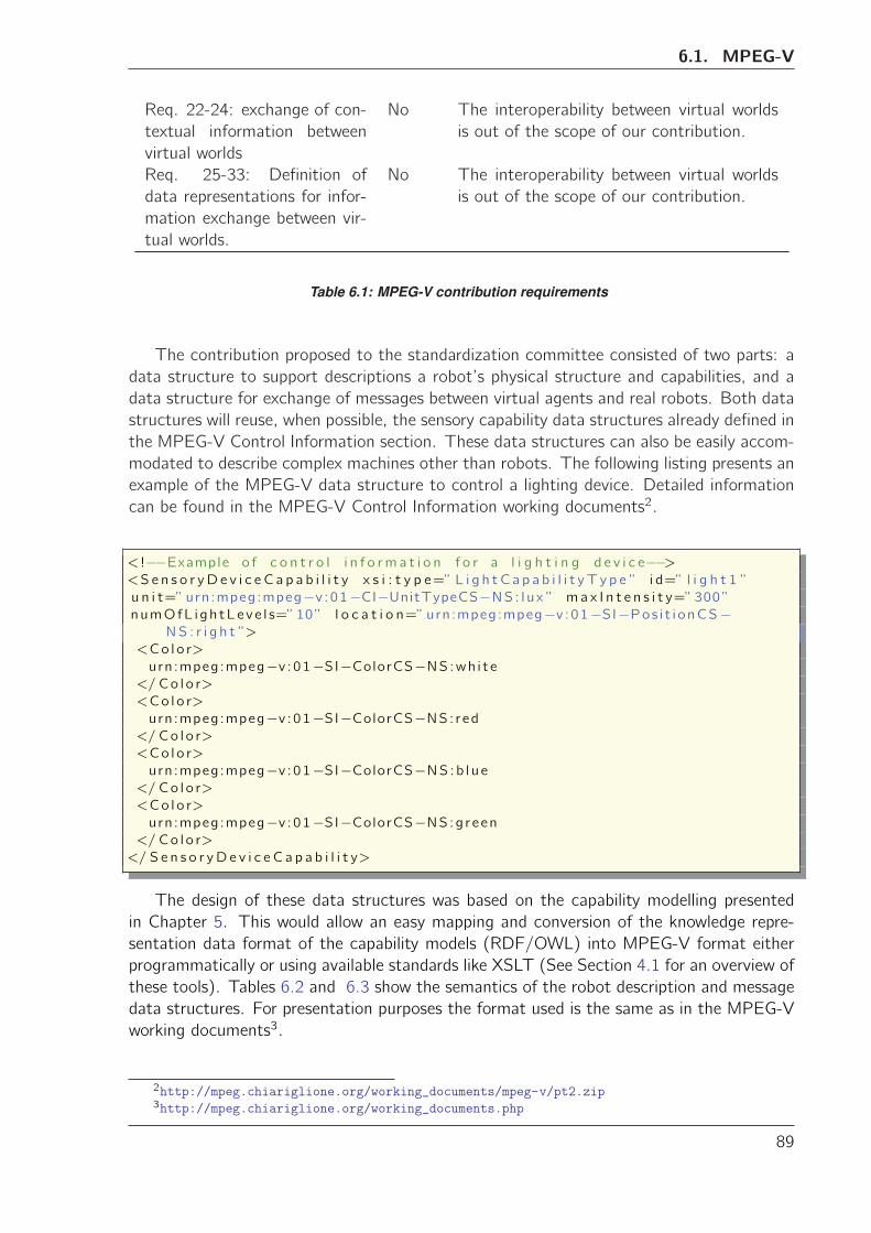
6.1. MPEG-V
Req. 22-24: exchange of con-
textual information between
virtual worlds
No The interoperability between virtual worlds
is out of the scope of our contribution.
Req. 25-33: Definition of
data representations for infor-
mation exchange between vir-
tual worlds.
No The interoperability between virtual worlds
is out of the scope of our contribution.
Table 6.1: MPEG-V contribution requirements
The contribution proposed to the standardization committee consisted of two parts: a
data structure to support descriptions a robot’s physical structure and capabilities, and a
data structure for exchange of messages between virtual agents and real robots. Both data
structures will reuse, when possible, the sensory capability data structures already defined in
the MPEG-V Control Information section. These data structures can also be easily accom-
modated to describe complex machines other than robots. The following listing presents an
example of the MPEG-V data structure to control a lighting device. Detailed information
can be found in the MPEG-V Control Information working documents2.
< !−−Example o f c o n t r o l i n f o rm a t i o n f o r a l i g h t i n g d e v i c e−−><S e n s o r yD e v i c e C a p a b i l i t y x s i : t y p e=” L i g h t C a p a b i l i t y T y p e ” i d=” l i g h t 1 ”
u n i t=”urn:mpeg:mpeg−v :01−CI−UnitTypeCS−NS : l u x ” ma x I n t e n s i t y=”300”numOfL i gh tLeve l s=”10” l o c a t i o n=”urn:mpeg:mpeg−v :01−SI−Pos i t i onCS−
NS : r i g h t ”>
<Co l o r>
urn:mpeg:mpeg−v :01−SI−ColorCS−NS:wh i t e</ Co l o r>
<Co l o r>
urn:mpeg:mpeg−v :01−SI−ColorCS−NS: red</ Co l o r>
<Co l o r>
urn:mpeg:mpeg−v :01−SI−ColorCS−NS:b l u e</ Co l o r>
<Co l o r>
urn:mpeg:mpeg−v :01−SI−ColorCS−NS:g reen</ Co l o r>
</ S e n s o r yD e v i c e C a p a b i l i t y>
The design of these data structures was based on the capability modelling presented
in Chapter 5. This would allow an easy mapping and conversion of the knowledge repre-
sentation data format of the capability models (RDF/OWL) into MPEG-V format either
programmatically or using available standards like XSLT (See Section 4.1 for an overview of
these tools). Tables 6.2 and 6.3 show the semantics of the robot description and message
data structures. For presentation purposes the format used is the same as in the MPEG-V
working documents3.
2http://mpeg.chiariglione.org/working˙documents/mpeg-v/pt2.zip3http://mpeg.chiariglione.org/working˙documents.php
89
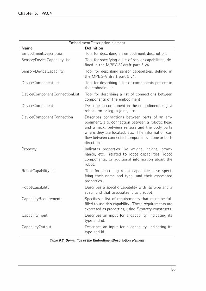
Chapter 6. PAC4
EmbodimentDescription element
Name Definition
EmbodimentDescription Tool for describing an embodiment description.
SensoryDeviceCapabilityList Tool for specifying a list of sensor capabilities, de-
fined in the MPEG-V draft part 5 v4.
SensoryDeviceCapability Tool for describing sensor capabilities, defined in
the MPEG-V draft part 5 v4.
DeviceComponentList Tool for describing a list of components present in
the embodiment.
DeviceComponentConnectionList Tool for describing a list of connections between
components of the embodiment.
DeviceComponent Describes a component in the embodiment, e.g. a
robot arm or leg, a joint, etc.
DeviceComponentConnection Describes connections between parts of an em-
bodiment, e.g. connection between a robotic head
and a neck, between sensors and the body parts
where they are located, etc. The information can
flow between connected components in one or both
directions.
Property Indicates properties like weight, height, prove-
nance, etc. related to robot capabilities, robot
components, or additional information about the
robot.
RobotCapabilityList Tool for describing robot capabilities also speci-
fying their name and type, and their associated
properties.
RobotCapability Describes a specific capability with its type and a
specific id that associates it to a robot.
CapabilityRequirements Specifies a list of requirements that must be ful-
filled to use this capability. These requirements are
expressed as properties, using Property constructs.
CapabilityInput Describes an input for a capability, indicating its
type and id.
CapabilityOutput Describes an input for a capability, indicating its
type and id.
Table 6.2: Semantics of the EmbodimentDescription element
90
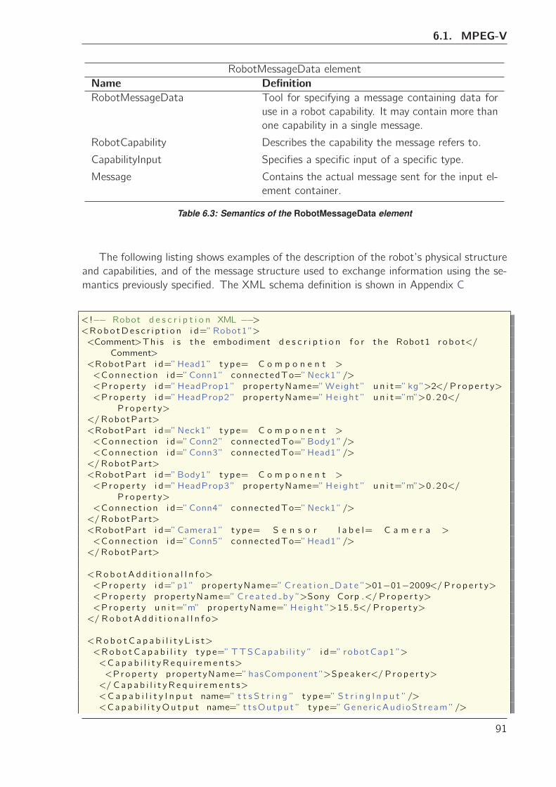
6.1. MPEG-V
RobotMessageData element
Name Definition
RobotMessageData Tool for specifying a message containing data for
use in a robot capability. It may contain more than
one capability in a single message.
RobotCapability Describes the capability the message refers to.
CapabilityInput Specifies a specific input of a specific type.
Message Contains the actual message sent for the input el-
ement container.
Table 6.3: Semantics of the RobotMessageData element
The following listing shows examples of the description of the robot’s physical structure
and capabilities, and of the message structure used to exchange information using the se-
mantics previously specified. The XML schema definition is shown in Appendix C
< !−− Robot d e s c r i p t i o n XML −−><Robo tDe s c r i p t i o n i d=”Robot1”>
<Comment>Th i s i s the embodiment d e s c r i p t i o n f o r the Robot1 r obo t</
Comment>
<RobotPart i d=”Head1” t ype= C o m p o n e n t >
<Connec t i on i d=”Conn1” connectedTo=”Neck1”/>
<Prop e r t y i d=”HeadProp1” propertyName=”Weight ” u n i t=”kg”>2</ P rop e r t y>
<Prop e r t y i d=”HeadProp2” propertyName=”He i gh t ” u n i t=”m”>0 .20</
P rop e r t y>
</RobotPart>
<RobotPart i d=”Neck1” t ype= C o m p o n e n t >
<Connec t i on i d=”Conn2” connectedTo=”Body1”/>
<Connec t i on i d=”Conn3” connectedTo=”Head1”/>
</RobotPart>
<RobotPart i d=”Body1” t ype= C o m p o n e n t >
<Prop e r t y i d=”HeadProp3” propertyName=”He i gh t ” u n i t=”m”>0 .20</
P rop e r t y>
<Connec t i on i d=”Conn4” connectedTo=”Neck1”/>
</RobotPart>
<RobotPart i d=”Camera1” t ype= S e n s o r l a b e l= C a m e r a >
<Connec t i on i d=”Conn5” connectedTo=”Head1”/>
</RobotPart>
<Ro b o tA d d i t i o n a l I n f o>
<Prop e r t y i d=”p1” propertyName=” C r e a t i o n Da t e ”>01−01−2009</ P rop e r t y><Prop e r t y propertyName=” Cr e a t e d b y ”>Sony Corp .</ P rop e r t y>
<Prop e r t y u n i t=”m” propertyName=”He i gh t ”>15 .5</ P rop e r t y>
</ R o b o tA d d i t i o n a l I n f o>
<Ro b o t C a p a b i l i t y L i s t>
<Rob o tC a p a b i l i t y t ype=”TTSCapab i l i t y ” i d=” robotCap1 ”>
<Ca p a b i l i t y R e q u i r em e n t s>
<Prop e r t y propertyName=”hasComponent”>Speake r</ P rop e r t y>
</ C a p a b i l i t y R e q u i r em e n t s>
<C a p a b i l i t y I n p u t name=” t t s S t r i n g ” t ype=” S t r i n g I n p u t ”/>
<Cap a b i l i t yOu t p u t name=” t t sOu tpu t ” t ype=”Gene r i cAud i oS t r eam ”/>
91
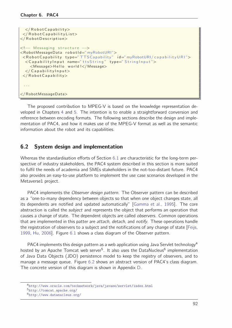
Chapter 6. PAC4
</ Ro b o tC a p a b i l i t y>
</ R o b o t C a p a b i l i t y L i s t>
</ Robo tDe s c r i p t i o n>
< !−− Messag ing s t r u c t u r e −−><RobotMessageData r o b o t I d=”myRobotURI”>
<Rob o tC a p a b i l i t y t ype=”TTSCapab i l i t y ” i d=”myRobotURI/ c a p a b i l i t y UR I ”>
<C a p a b i l i t y I n p u t name=” t t s S t r i n g ” t ype=” S t r i n g I n p u t ”>
<Message>He l l o wo r l d !</Message>
</ C a p a b i l i t y I n p u t>
</ Ro b o tC a p a b i l i t y>
. . .
</RobotMessageData>
The proposed contribution to MPEG-V is based on the knowledge representation de-
veloped in Chapters 4 and 5. The intention is to enable a straightforward conversion and
reference between encoding formats. The following sections describe the design and imple-
mentation of PAC4, and how it makes use of the MPEG-V format as well as the semantic
information about the robot and its capabilities.
6.2 System design and implementation
Whereas the standardisation efforts of Section 6.1 are characteristic for the long-term per-
spective of industry stakeholders, the PAC4 system described in this section is more suited
to fulfil the needs of academia and SMEs stakeholders in the not-too-distant future. PAC4
also provides an easy-to-use platform to implement the use case scenarios developed in the
Metaverse1 project.
PAC4 implements the Observer design pattern. The Observer pattern can be described
as a “one-to-many dependency between objects so that when one object changes state, all
its dependents are notified and updated automatically” [Gamma et al., 1995]. The core
abstraction is called the subject and represents the object that performs an operation that
causes a change of state. The dependent objects are called observers. Common operations
that are implemented in this patter are attach, detach, and notify. These operations handle
the registration of observers to a subject and the notifications of any change of state [Feijs,
1999, Hu, 2006]. Figure 6.1 shows a class diagram of the Observer pattern.
PAC4 implements this design pattern as a web application using Java Servlet technology4
hosted by an Apache Tomcat web server5. It also uses the DataNucleus6 implementation
of Java Data Objects (JDO) persistence model to keep the registry of observers, and to
manage a message queue. Figure 6.2 shows an abstract version of PAC4’s class diagram.
The concrete version of this diagram is shown in Appendix D.
4http://www.oracle.com/technetwork/java/javaee/servlet/index.html5http://tomcat.apache.org/6http://www.datanucleus.org/
92
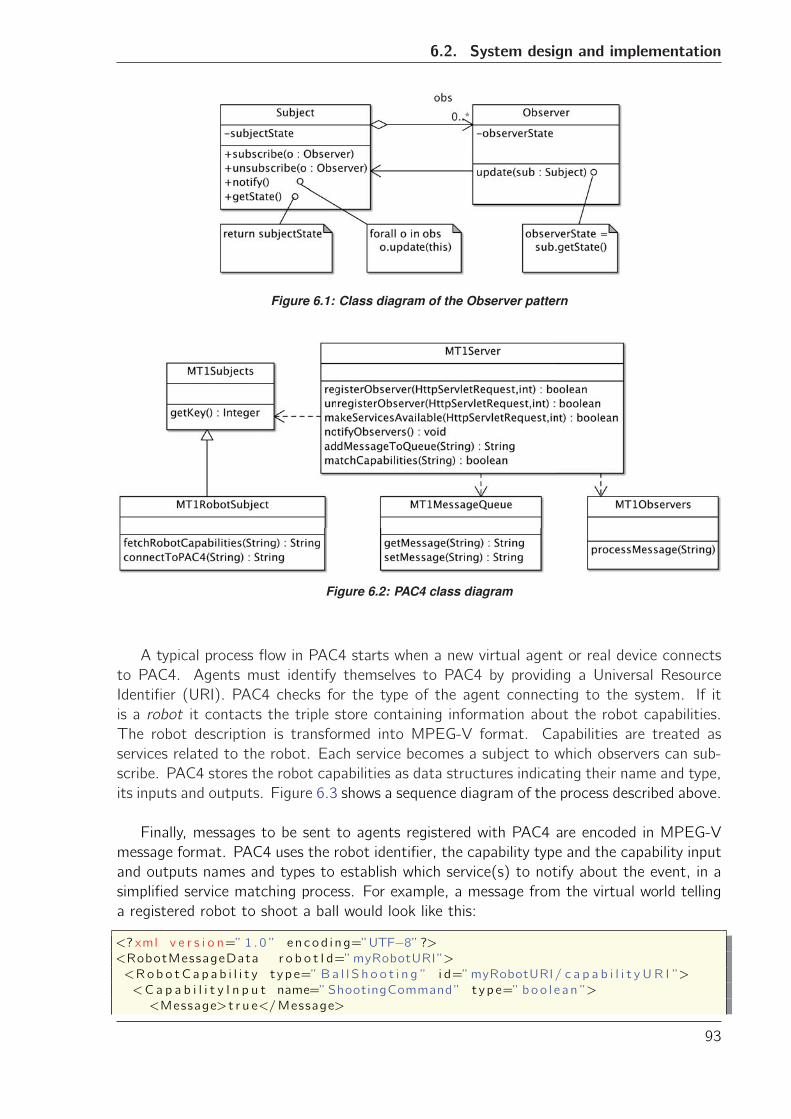
6.2. System design and implementation
Figure 6.1: Class diagram of the Observer pattern
Figure 6.2: PAC4 class diagram
A typical process flow in PAC4 starts when a new virtual agent or real device connects
to PAC4. Agents must identify themselves to PAC4 by providing a Universal Resource
Identifier (URI). PAC4 checks for the type of the agent connecting to the system. If it
is a robot it contacts the triple store containing information about the robot capabilities.
The robot description is transformed into MPEG-V format. Capabilities are treated as
services related to the robot. Each service becomes a subject to which observers can sub-
scribe. PAC4 stores the robot capabilities as data structures indicating their name and type,
its inputs and outputs. Figure 6.3 shows a sequence diagram of the process described above.
Finally, messages to be sent to agents registered with PAC4 are encoded in MPEG-V
message format. PAC4 uses the robot identifier, the capability type and the capability input
and outputs names and types to establish which service(s) to notify about the event, in a
simplified service matching process. For example, a message from the virtual world telling
a registered robot to shoot a ball would look like this:
<? xml v e r s i o n=” 1 .0 ” encod i ng=”UTF−8”?><RobotMessageData r o b o t I d=”myRobotURI”>
<Rob o tC a p a b i l i t y t ype=” Ba l l S h o o t i n g ” i d=”myRobotURI/ c a p a b i l i t y UR I ”>
<C a p a b i l i t y I n p u t name=”ShootingCommand” t ype=” boo l e an ”>
<Message>t r u e</Message>
93
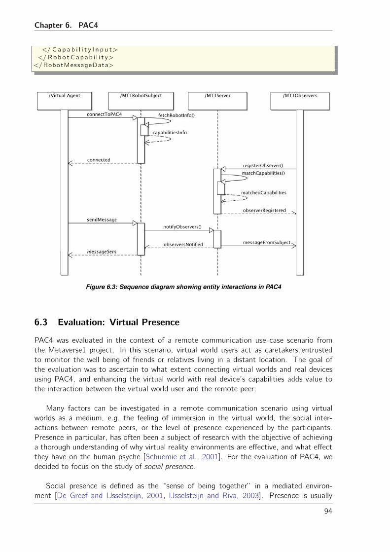
Chapter 6. PAC4
</ C a p a b i l i t y I n p u t>
</ Ro b o tC a p a b i l i t y>
</RobotMessageData>
Figure 6.3: Sequence diagram showing entity interactions in PAC4
6.3 Evaluation: Virtual Presence
PAC4 was evaluated in the context of a remote communication use case scenario from
the Metaverse1 project. In this scenario, virtual world users act as caretakers entrusted
to monitor the well being of friends or relatives living in a distant location. The goal of
the evaluation was to ascertain to what extent connecting virtual worlds and real devices
using PAC4, and enhancing the virtual world with real device’s capabilities adds value to
the interaction between the virtual world user and the remote peer.
Many factors can be investigated in a remote communication scenario using virtual
worlds as a medium, e.g. the feeling of immersion in the virtual world, the social inter-
actions between remote peers, or the level of presence experienced by the participants.
Presence in particular, has often been a subject of research with the objective of achieving
a thorough understanding of why virtual reality environments are effective, and what effect
they have on the human psyche [Schuemie et al., 2001]. For the evaluation of PAC4, we
decided to focus on the study of social presence.
Social presence is defined as the “sense of being together” in a mediated environ-
ment [De Greef and IJsselsteijn, 2001, IJsselsteijn and Riva, 2003]. Presence is usually
94
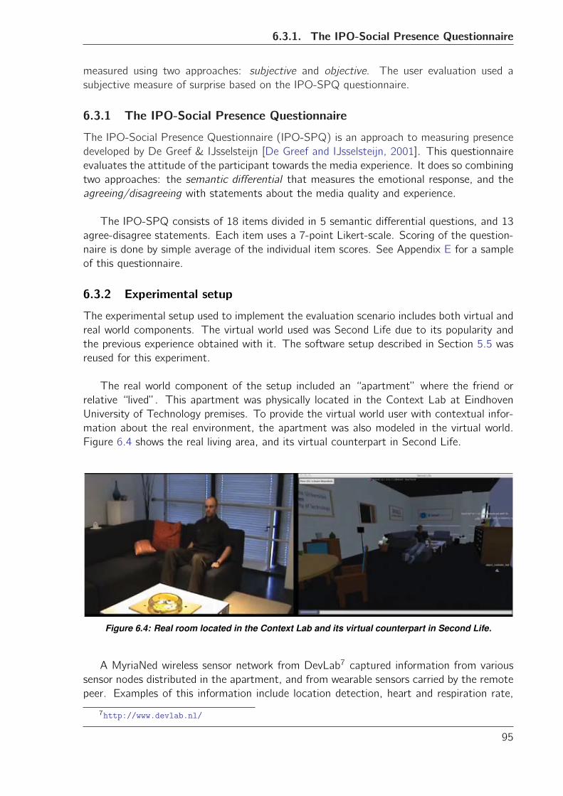
6.3.1. The IPO-Social Presence Questionnaire
measured using two approaches: subjective and objective. The user evaluation used a
subjective measure of surprise based on the IPO-SPQ questionnaire.
6.3.1 The IPO-Social Presence Questionnaire
The IPO-Social Presence Questionnaire (IPO-SPQ) is an approach to measuring presence
developed by De Greef & IJsselsteijn [De Greef and IJsselsteijn, 2001]. This questionnaire
evaluates the attitude of the participant towards the media experience. It does so combining
two approaches: the semantic differential that measures the emotional response, and the
agreeing/disagreeing with statements about the media quality and experience.
The IPO-SPQ consists of 18 items divided in 5 semantic differential questions, and 13
agree-disagree statements. Each item uses a 7-point Likert-scale. Scoring of the question-
naire is done by simple average of the individual item scores. See Appendix E for a sample
of this questionnaire.
6.3.2 Experimental setup
The experimental setup used to implement the evaluation scenario includes both virtual and
real world components. The virtual world used was Second Life due to its popularity and
the previous experience obtained with it. The software setup described in Section 5.5 was
reused for this experiment.
The real world component of the setup included an “apartment” where the friend or
relative “lived”. This apartment was physically located in the Context Lab at Eindhoven
University of Technology premises. To provide the virtual world user with contextual infor-
mation about the real environment, the apartment was also modeled in the virtual world.
Figure 6.4 shows the real living area, and its virtual counterpart in Second Life.
Figure 6.4: Real room located in the Context Lab and its virtual counterpart in Second Life.
A MyriaNed wireless sensor network from DevLab7 captured information from various
sensor nodes distributed in the apartment, and from wearable sensors carried by the remote
peer. Examples of this information include location detection, heart and respiration rate,
7http://www.devlab.nl/
95
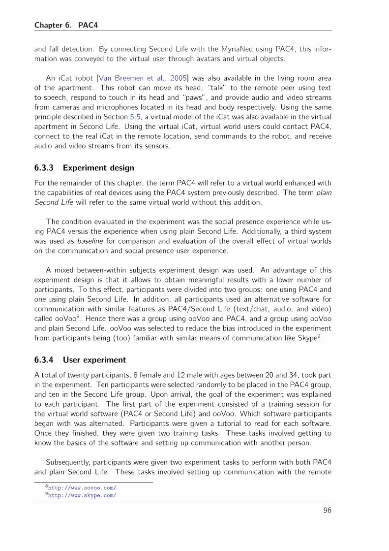
Chapter 6. PAC4
and fall detection. By connecting Second Life with the MyriaNed using PAC4, this infor-
mation was conveyed to the virtual user through avatars and virtual objects.
An iCat robot [Van Breemen et al., 2005] was also available in the living room area
of the apartment. This robot can move its head, “talk” to the remote peer using text
to speech, respond to touch in its head and “paws”, and provide audio and video streams
from cameras and microphones located in its head and body respectively. Using the same
principle described in Section 5.5, a virtual model of the iCat was also available in the virtual
apartment in Second Life. Using the virtual iCat, virtual world users could contact PAC4,
connect to the real iCat in the remote location, send commands to the robot, and receive
audio and video streams from its sensors.
6.3.3 Experiment design
For the remainder of this chapter, the term PAC4 will refer to a virtual world enhanced with
the capabilities of real devices using the PAC4 system previously described. The term plain
Second Life will refer to the same virtual world without this addition.
The condition evaluated in the experiment was the social presence experience while us-
ing PAC4 versus the experience when using plain Second Life. Additionally, a third system
was used as baseline for comparison and evaluation of the overall effect of virtual worlds
on the communication and social presence user experience.
A mixed between-within subjects experiment design was used. An advantage of this
experiment design is that it allows to obtain meaningful results with a lower number of
participants. To this effect, participants were divided into two groups: one using PAC4 and
one using plain Second Life. In addition, all participants used an alternative software for
communication with similar features as PAC4/Second Life (text/chat, audio, and video)
called ooVoo8. Hence there was a group using ooVoo and PAC4, and a group using ooVoo
and plain Second Life. ooVoo was selected to reduce the bias introduced in the experiment
from participants being (too) familiar with similar means of communication like Skype9.
6.3.4 User experiment
A total of twenty participants, 8 female and 12 male with ages between 20 and 34, took part
in the experiment. Ten participants were selected randomly to be placed in the PAC4 group,
and ten in the Second Life group. Upon arrival, the goal of the experiment was explained
to each participant. The first part of the experiment consisted of a training session for
the virtual world software (PAC4 or Second Life) and ooVoo. Which software participants
began with was alternated. Participants were given a tutorial to read for each software.
Once they finished, they were given two training tasks. These tasks involved getting to
know the basics of the software and setting up communication with another person.
Subsequently, participants were given two experiment tasks to perform with both PAC4
and plain Second Life. These tasks involved setting up communication with the remote
8http://www.oovoo.com/9http://www.skype.com/
96
6.3.5. Experiment results
peer and enquiring about their state and well being. Audio and video streams ware available
within the virtual world. Participants using PAC4 could also use the robot to “look around”,
as well as the text-to-speech capabilities to “talk” to the remote peer. Upon completing the
tasks they were presented with a Social Presence Questionnaire to assess social presence.
Once the participants finished with both software and their respective IPO-SPQ, they were
presented with an open-ended questionnaire to capture their general opinions on the system,
privacy, presence, and connectedness. Both questionnaires can be seen in Appendix E.
6.3.5 Experiment results
As mentioned previously, the software ooVoo was used as a baseline system to measure the
effect of virtual worlds in the feeling of presence, in comparison with other, more traditional
forms of communication.
An analysis of covariance (ANCOVA) was performed over the measure of presence.
The results are presented in three parts: first results related to the overall measure of social
presence consisting of the average (adjusted) scores for the complete IPO-SPQ. Second
are results related to the semantic differential questions in IPO-SPQ (items 1-5). Third
are results related to the agree-disagree section of the IPO-SPQ (items 6-18).
6.3.5.1 Overall measure of presence
A one-way between-groups analysis of covariance was conducted to compare the effec-
tiveness of two different communication systems designed to measure the level of social
presence experienced by the participants in a remote communication scenario. The in-
dependent variable was the type of system used (PAC4, plain Second Life) and the de-
pendent variable consisted on the scores of the IPO-SPQ questionnaire administered after
the participants completed the indicated tasks with the communication systems. The es-
timated mean score values and standard deviation for PAC4 and plain Second Life were
M = 4.000,Std. Dev. = 0.685 and M = 3.806,Std. Dev. = 0.946 respectively. The IPO-
SPQ scores related to the software ooVoo were used as the covariate in this analysis. After
adjusting for the covariates there were no significant differences between the two com-
munication system groups (PAC4 and plain Second Life) on the scores for the IPO-SPQ,
F (1, 17) = 0.554, p = 0.467, eta squared = 0.032. There was a moderate relationship
between the covariate and the independent variable as indicated by an eta squared = 0.054.
The analysis of the video recordings taken during the experiment and the responses
to the open-ended questions, showed divided opinion over the benefits of PAC4 over plain
Second Life. Most participants stated that they felt “more connected” to the remote peer,
and that PAC4 provides “better information about the other person” than the alternative
communication software. However, several mentioned that there might be issues with
privacy as “I can see information about the other person even when the person is not online
or is not chatting with me”.
6.3.5.2 Semantic differential measure of presence
The estimated mean score values and standard deviation for the semantic differential section
of IPO-SPQ, for both PAC4 and plain Second Life were M = 3.700,Std. Dev. = 0.896
97
Chapter 6. PAC4
Figure 6.5: Mean scores of the overall level of presence experienced by the participants while usingPAC4 vs plain Second Life
and M = 3.460,Std. Dev. = 0.859 respectively. The IPO-SPQ scores of the participants
related to the software ooVoo were used as the covariate in this analysis. After adjusting for
the covariates there were no significant differences between the two communication system
groups (PAC4 and plain Second Life) on the scores for the IPO-SPQ, F (1, 17) = 0.392,
p = 0.540, eta squared = 0.023. There was a small relationship between the covariate and
the independent variable a indicated by an eta squared = 0.034.
6.3.5.3 Agree-disagree measure of presence
The estimated mean score values and standard deviation for the agree-disagree section of
IPO-SPQ, for both PAC4 and plain Second Life were M = 4.115,Std. Dev. = 0.842 and
M = 3.939,Std. Dev. = 1.046 respectively. The IPO-SPQ scores of the participants re-
lated to the software ooVoo were used as the covariate in this analysis. After adjusting for
the covariates there were no significant differences between the two communication system
groups (PAC4 and plain Second Life) on the scores for the IPO-SPQ, F (1, 17) = 0.483,
p = 0.496, eta squared = 0.028. There was a moderate relationship between the covariate
and the independent variable a indicated by an eta squared = 0.064.
The higher scores of PAC4 in the semantic differential section suggest that the effect
over the feeling of presence has a strong affective component, e.g. warm, personal, affective,
sensitive. The lower scores in the agree-disagree section indicate poorer acceptance of the
communication medium, and a less positive perception of the participants about the system
qualities, e.g. usability, sense of realism, etc.
98
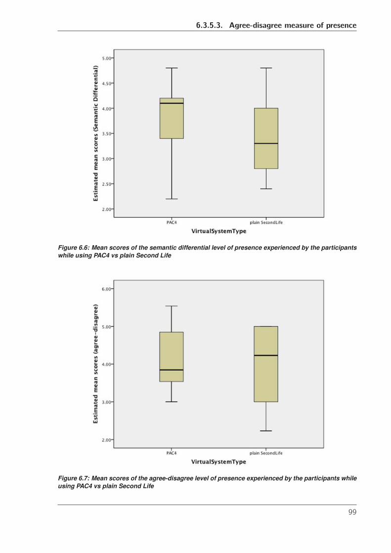
6.3.5.3. Agree-disagree measure of presence
Figure 6.6: Mean scores of the semantic differential level of presence experienced by the participantswhile using PAC4 vs plain Second Life
Figure 6.7: Mean scores of the agree-disagree level of presence experienced by the participants whileusing PAC4 vs plain Second Life
99
Chapter 6. PAC4
6.3.6 Discussion
The results obtained from the experiments on social presence, indicate that although the
participants appreciate the potential of PAC4 as an enabling technology for remote commu-
nication and care situations, they perceive a large overhead and complexity in the currently
available software tools for virtual worlds.
Particularly interesting were the observations of several participants who mentioned that
alternative means of communication like VoIP software (e.g. Skype, ooVoo, etc.) were in-
deed simpler to understand, faster, and in general, more familiar to them than virtual
environments like Second Life. Some participants went further to comment that even mov-
ing around in the virtual world, and talking to others through an avatar or a robot was just
too complicated and unnatural.
All this seems to suggest that in general, virtual worlds technology is not mature enough
to allow for meaningful interactions and applications where efficient remote communication
is needed, making users feel that virtual worlds are more a hindrance than a facilitator.
Furthermore, the overall impression is that the level of presence experienced by the partic-
ipants is not related to the differentiating aspects of virtual worlds such as the simulated
(3D) environment, the avatar motion and expressions, and the social interactions that are
possible in such environment. In fact, the participants indicated that although having a
robot they could remotely control helped them to feel more connected and more aware of
what happened in the remote location, they felt that they were equally present when they
could talk to the remote person without the mediation of a virtual representation.
In this context, the results of the evaluation of PAC4 should be seen under the right light.
Although the questionnaire scores indicate that PAC4 indeed improves the level of presence
with respect to plain Second Life, the fact that the overall evaluation of virtual worlds by
the participants is not positive produces a negative effect in the overall appreciation of
any virtual world-based software. This is a likely explanation as to why the results of the
evaluation are not statistically significant.
6.4 Concluding remarks
This chapter presented PAC4, a prototype of service registration system developed in the
context of the Metaverse1 project to connect virtual worlds and real robots and other
devices. It also introduced the contribution proposed by the author to the upcoming stan-
dard MPEG-V. This contribution was submitted to the standardization committee at the
93rd. WG11 MPEG meeting in July, 2010 at International Telecommunication Union (ITU),
Geneva. There it was labelled as Interesting for Consideration, and will be invited for further
consideration for the first revision of the standard [Gelissen, 2010]. PAC4 implements the
proposed MPEG-V robot description and message exchange formats.
A user experiment was conducted to evaluate the effect of enhancing the features of a
virtual world by connecting real robots and other devices to it, enabling their use from within
the virtual environment. The selection of the use case upon which the experiment was built
had two main motivations. On one hand was the intention of presenting the technology
100
6.4. Concluding remarks
developed during this PhD project in a scenario of social relevance, namely, the human
experience of presence in an environment by means of a communication medium, which is
the very definition of telepresence [Steuer, 1992]. On the other hand was the desire of the
Metaverse1 project and MPEG-V stakeholders to showcase their own technologies, which
in turn are related to assisted living, remote care, and communication.
Telepresence is a current topic of research in Human Robot Interaction (HRI). Telepres-
ence itself is manifested in a large number of applications that involve interaction through
video. This has originated the perception of telepresence robots as “embodied video con-
ferencing on wheels” [Tsui et al., 2011]. At the same time, telepresence has been a topic
traditionally associated to virtual and mixed reality. In fact, one of the strong commer-
cial pitches of the virtual world Second Life has been the ability to organize meetings and
teleconferences where people from all over the world gather and be “present” in the same
virtual space. In this context, virtual worlds offer an alternative environment for meaning-
ful human-robot, human-machine, and human-human interaction in telepresence scenarios.
Moreover, telepresence also has important applications in education and training [Gillet
et al., 1997], and in the medical and health care domains [Ballantyne, 2002]. Demonstrat-
ing the possibility of combining the strengths of both domains in telepresence and using the
technology developed in this PhD in such context will increment its intrinsic value as an
alternative, attractive tool to implement applications that enrich the interaction between
remote peers.
At the same time, the chosen experiment scenario was a socially relevant common
ground where the Metaverse1 project and MPEG-V stakeholders could identify themselves
and their products and technologies, e.g. Philips and their telepresence robot iCat, and
DevLab and their MyriaNed sensor network monitoring application.
The results of the experiment indicate that PAC4 indeed adds value to the human expe-
rience of presence when using a virtual world coupled to a robot in a remote communication
and care scenario. However, it was also apparent that virtual world applications and tech-
nologies are not yet ready to compete with alternative forms of communication. Although
virtual worlds have been heralded to bring a new way of communicating, interacting, and
relating to each other, they are still perceived as slow, cumbersome, and overly complicated.
This perception was evident in the opinions gathered from the experiment participants.
One example is the reflection of a participant who expressed that “there is potential in being
able to recreate a room in the virtual world, and then use a real robot to see what a person
is doing in the real room. That made me feel more connected and have a better idea of
what was happening. However, I think that the whole virtual world thing is too complicated
to use practically”. Other participants had similar statements saying that they “found it
difficult to get used to moving around in the virtual world”, or that “being able to move
the robot is cool, but the virtual world thing is creepy”. If one takes into consideration that
the virtual world used (Second Life) is considered in the virtual world community to be a
baseline reference system with simple-to-use features and interactions, the results obtained
in the experiment seem to indicate a need for a shift in usability paradigms for virtual world
applications.
101
Chapter 6. PAC4
It must be said that the experiment results put us with our feet on the ground again.
As previously mentioned, one of the strengths of virtual worlds has been the ability to pro-
vide form to remote interaction between peers. Virtual world users can experiment with
new ways of meeting people and communicating with them overcoming distance, gender,
and appearance barriers. Similarly, the value of robotic devices in telepresence situations
has been already proven by the HRI community. The choice of a traditional telepresence
scenario, where virtual worlds and robotics have already proven their value and utility, was
intentionally directed to show the improvement that could be gained by combining both
domains. The resulting user perception that virtual worlds were more a hindrance than
a facilitator in such basic telepresence scenario contradicts to some extent the previous
statements.
The interpretation that I made of these results is that although the potential of the new
technology described in this chapter is indeed recognized by the users, it will require more
research and development of new virtual world usability and interaction paradigms for the
technology to be a success. Although in this particular study case the added complexity
of the combination of virtual worlds and real robots did not not pay off, there are other
applications where I would expect that it makes a difference for users in either domain.
More concretely, I believe that in applications scenarios like the robot rescue operators
training or the remote health care scenario described in Section 1.1, using the virtual world
as an interface that better resembles the real working environment in remote control and
monitoring situations can have a considerable positive impact, improving currently available
technologies and techniques. It is also possible that introducing new interfaces like Kinect
sensors, wearable sensors, and immersive environments will add the usability and “wow
factors” that the current computer screen, mouse and keyboard lack. This is certainly an
interesting and exciting avenue for future research.
102
Chapter
7Conclusions
This chapter presents a summary of the results obtained, the lessons learned, and their
implications, as well as possible future avenues of research.
The main goal of this PhD project was to fill in the existing interoperability gap be-
tween the interfaces of virtual worlds and those of real robots. The strategy chosen was to
focus on the design of an interface that would “open” robots and their capabilities to be
accessed by virtual world and web applications using available standards and best practices.
An added benefit of this strategy was the decoupling of robot capability representation and
implementation.
Semantic Web technologies were chosen to this effect for two reasons: a) they are
a sound, proven mechanism to encode knowledge and make it available to heterogeneous
web applications, and b) they provide great flexibility to model knowledge about complex
domains, a characteristic that is essential given the evolving nature of robotic devices. In-
terestingly, despite the fact that Semantic Web technologies have been available for almost
a decade, their use in the robotics domain is almost non-existent. The impression obtained
during the course of this PhD project is that the reason behind this observation is that
only recently have Semantic Web technologies reached the maturity and expressive power
necessary to be practically useful in domains other than information processing on the Web.
Examples of these “mature” technologies are the recent introduction of OWL2 and SWRL
recommendations, the continuous development of Semantic Web tools like Protege, and
different mechanisms for knowledge engineering.
Despite these recent developments, Semantic Web knowledge modelling of complex do-
mains is still a daunting task. In the case of robotic devices, the knowledge required to
describe a robot’s physical embodiment and its capabilities goes beyond the basic knowl-
103
Chapter 7. Conclusions
edge of a casual reader or ontology hobbyist. This is further compounded by the large
heterogeneity of robot devices and the struggle of the robotics community to reach agree-
ment on best practices, and even terminology related to robots and robotics. RoboDB was
developed in an effort to address these issues.
RoboDB is a web-based system utilizing Semantic Web technologies with two main ob-
jectives: to leverage the user’s need of ontology engineering knowledge to describe a robot
embodiment, and to provide a platform where the robotics community can contribute, dis-
cuss, and evolve the knowledge about robots and robotics. Both aspects are crucial for the
success of this PhD project, as the first will provide the information necessary to build the
interfaces that enable interoperability between virtual worlds and real robots, while the sec-
ond will ensure that this information is generated and maintained in a sustainable way. The
development of RoboDB answers research question number 2 (see Section 1.3.1) related
to creating knowledge about robots in a sustainable, organized and flexible way, and using
appropriate technologies to make this knowledge available to the community. Chapter 4
describes in detail the design decisions behind the development of this system.
Through the several iterations of the design and development process of RoboDB, many
lessons were learned. Some of these lessons are:
• Real-world users are not interested in becoming Semantic Web experts. Althoughusers acknowledged the importance of adding meaning to the robot descriptions,
they wanted a tool that would guide them in the process of creating semantic data,
and not require them to know much about Semantic Web. The perception of the
system was affected by the apparent difficulty of modelling the robot structure and
capabilities. Subtle details like changing the user interface of Semantic Mediawiki,
and adding interactively guided processes to the robot structure’s modelling greatly
improved the acceptance of the system.
• Freedom and usability are at opposite ends of the spectrum. The balance betweenbuilding a simplified, semi-automatic mechanism to create semantic information and
the freedom needed to generate knowledge about constantly changing concepts is
hard to find. This is especially true when modelling knowledge about evolving devices
such as robots. The choice of system features that need to be automated and
restricted versus those that can be left open to the user was crucial for the success
of this system.
• Creation of content about robots is a major task. The rate of development of robotsmakes it unfeasible that a single person or even a small group of people models all
available robot embodiments. Therefore, the community oriented, crowd sourcing-
like approach of RoboDB is important to ensure the sustainability of the knowledge
generation. The robotics community recognizes this issue, and is willing to contribute
to it, as was patently clear with the acceptance and involvement of RoboNed in the
RoboDB development.
It must be mentioned that although there is a wealth of information about robots and
robotics on the Web, to the best of my knowledge there is no community-oriented (or oth-
erwise) system specifically designed to describe robots using Semantic Web technologies,
104
Chapter 7. Conclusions
capturing their structure characteristics and modelling their capabilities. RoboDB is then a
novel contribution in this domain.
Another important result of this PhD project is the knowledge engineering process de-
scribed in Chapter 5. Although the idea of describing the capabilities of a robot in terms
of inputs, outputs, requirements and effects is not new, its application for interoperability
between virtual world applications and robotic devices using the Semantic Web is certainly
original. Furthermore, previous attempts to use Semantic Web technologies to describe
robots have been isolated and developed ad-hoc solutions for a specific type of robot (see
Chapter 1). In this PhD project I have shown the potential of the semantic approach to ad-
dress the needs of heterogeneous robot embodiments. The specification of the knowledge
engineering process in addition to the RoboDB system is an answer to research question
number 1 (see Section 1.3.1) on how to capture the essential aspects of robot heterogene-
ity and their capabilities, and make this information available on the web. The effort to
achieve generality in the information exchange between virtual and real agents has been
emphasized by the contribution to the upcoming MPEG-V standard, a contribution that is
based on the capability modelling described in Chapter 5. The hope is that as industry and
academia embrace this new standard, the knowledge engineering process described in this
document will also become relevant for interoperability efforts in other domains.
The ROILAbot case study showed how the capability representation developed as part
of the knowledge engineering process can be used in two ways: firstly, it can be transformed
into alternative representations like the MPEG-V format mentioned above, effectively en-
abling the information exchange between virtual agents in Second Life and the ROILAbot
robot. Secondly, it showed how semantic information was used to create interaction pat-
terns and new capabilities that can be added to the robot without the need of expertise
to modify the internal robot control source code. An example of this is the automatic
translation from English to ROILA. These results provide an answer to research question
number 3 (see Section 1.3.1).
It is important to emphasize that the strength of the semantic approach used in this
project to represent robots and their capabilities, lies in the ability to describe complex sys-
tems and give meaning to the concepts generated in these descriptions. Furthermore, the
proven flexibility and scalability of Semantic Web technologies in the information processing
domain ensures that the knowledge about robots can be managed and reused as the domain
complexity grows.
Unfortunately, in the strength lies also the weakness of the approach. Semantic Web
technologies more often than not trade flexibility and scalability for performance. This
means that while reasoning engines are able to perform complex inferences, check for in-
tegrity of the knowledge base, and even suggest repair operations, all this comes at the
cost of an increase in the time and computing resources needed to that effect. In this PhD
project the focus has been on creating the interfaces that enable interoperability. Although
the implementation of the use cases from Chapter 5 and 6 demonstrate that a practical
use of these interfaces is feasible, it is also clear that there are other factors that need to
be taken into account when implementing more complex systems. For example, robotic
systems in the medical and industrial domains often have soft- and/or real-time constraints
105
Chapter 7. Conclusions
for their operation. Connecting a virtual world to these kinds of systems for simulation
of real life situations would need to address the issues of modifying the requirements and
effects of robot capabilities to include temporal ontology elements. Additionally, it would
need to implement the new interfaces while taking these time constraints, and Semantic
Web tools performance into account. While there are some approaches in the Semantic
Web domain that look into temporal issues and increased search and inference performance,
their application to the robotics domain is not straightforward. I believe that this is an in-
teresting avenue of research to be explored in the near future that will make the semantic
approach to describe robots much more robust.
The system PAC4 was developed to showcase the use of the semantic descriptions of
robots and the MPEG-V information exchange format in a more general scenario. Note
that this complements the answer to research question number 3, related to the reuse of
the robot structural and capability descriptions in different interaction scenarios. PAC4 was
implemented using the observer design pattern and works as a service registry application
that matches robot capabilities described using Semantic Web technologies, with requests
coming from web applications. This match is performed based on qualified names and
types of capability inputs and outputs. It can be argued that there are more powerful, ele-
gant algorithms and tools to perform semantic matching (e.g. S-Match [Giunchiglia et al.,
2004]). However, the goal of PAC4 was to show the real-world application of the seman-
tic descriptions of robot capabilities. Therefore, a design decision was made to simplify
the implementation of PAC4, and focus instead on the user experience while using this sys-
tem. Semantic matching algorithms and tools are interesting research topics that could lead
to improvements in the actual implementation of capabilities, and should be further studied.
The final result of this PhD project was the study on the effect of a virtual world
connected to, and enhanced with robot capabilities on the virtual user’s feeling of social
presence (see research question number 4, Section 1.3.1). As discussed in Chapter 6, social
presence is one of the aspects that have been studied the most to explain why virtual worlds
are effective as communication and interaction mediums. The hypothesis tested was that
enabling the virtual world user to connect to a remote real robot using PAC4, and to use
its capabilities in a remote communication scenario, produced an increase on the level of
social presence felt by the virtual world user, adding value to his/her experience while using
the system.
This study reported that users evaluated PAC4 as providing a better overall feeling of
presence than plain Second Life, however, the difference in scores between both systems
was not statistically significant. The analysis of this result shed some light on an interest-
ing phenomena occurring when comparing virtual world software to alternative means of
communication like VoIP software. Virtual environments have been heralded as the step-
ping stone to achieve a sense of togetherness and to change the way of interaction and
communication with remote peers in a common (virtual) place [Durlach and Slater, 2000].
The results obtained in the experiment, however, point to the contrary: users perceived the
virtual world more as a hindrance than a facilitator in the communication tasks they were
presented with. This was emphasized by the users’ comments to the open ended questions
presented at the end of the experiment: they felt more connected and present when they
were controlling the robot from within the virtual world, but altogether, they felt that mov-
106
Chapter 7. Conclusions
ing around in the virtual environment, interacting with virtual objects, and using the virtual
world software was more of a limitation to the communication. Some users went as far as
to call the virtual world interface “cumbersome”, “really complex”, and “creepy”.
It can be argued that these results were also affected by the small sample of partici-
pants and the fact that the scenario was artificially crafted and tested. While this is true,
I believe that the sample was well balanced, with participants with few or no knowledge of
virtual worlds, similar education level, ages equally distributed in the “young adults” cate-
gory, and similar gender distribution. Furthermore, the simplicity of the use case scenario
and the controlled conditions under which the experiment was executed should have made
it fairly easy for all applications to compete on equal grounds. Therefore, I believe that
these results should not be taken lightly. In fact, this is a strong indication that virtual
world research might do well in investigating and revising the usability paradigms of cur-
rent virtual world applications, and their suitability for communication and interaction tasks.
The efforts to achieve interoperability between virtual and real domains do not stop
here. As virtual worlds increase their presence in our lives, their reach into our reality will
also increase. This PhD has laid a foundation to connect real robots to virtual worlds, and
it is not difficult to imagine that the same principles can be applied to connect robots to
other web applications and networked devices, and exchange information with them. When
this is achieved, the transition from a Semantic Web for robots to a true Semantic Web of
robots will be complete.
107

Bibliography
[ABB, 2008] ABB (2008). ABB Robotics remote service solution. Available Online: http:
//www.abb.com/cawp/seitp202/d878f3de2823ac5ec12574b3004d5539.aspx.
[Alers and Hu, 2009] Alers, S. and Hu, J. (2009). AdMoVeo: A robotic platform for teach-
ing creative programming to designers. Learning by playing. Game-based education sys-
tem design and development, pages 410–421.
[Apple Inc., 2007] Apple Inc. (2007). Apple TV - press release. http://www.apple.com/
pr/library/2007/01/09Apple-TV-Coming-to-Your-Living-Room.html.
[Arkin, 1987] Arkin, R. (1987). Motor schema-based mobile robot navigation. In Proceed-
ings of the IEEE International Conference on Robotics and Automation, pages 264–271.
[Awaad et al., 2008] Awaad, I., Hartanto, R., Leon, B., and Ploger, P. (2008). A software
system for robotic learning by experimentation. Simulation, Modeling, and Programming
for Autonomous Robots, pages 99–110.
[Azuma et al., 1997] Azuma, R. et al. (1997). A survey of augmented reality. Presence-
Teleoperators and Virtual Environments, 6(4):355–385.
[Bainbridge, 2007] Bainbridge, W. (2007). The scientific research potential of virtual
worlds. science, 317(5837):472.
[Bakken, 2002] Bakken, D. (2002). Middleware. Encyclopedia of Distributed Computing.
[Ballantyne, 2002] Ballantyne, G. (2002). Robotic surgery, telerobotic surgery, telepres-
ence, and telementoring. Surgical Endoscopy, 16(10):1389–1402.
[Bangor et al., 2009] Bangor, A., Kortum, P., and Miller, J. (2009). Determining what
individual sus scores mean: Adding an adjective rating scale. Journal of Usability Studies,
4(3):114–123.
[Bartle, 2004] Bartle, R. (2004). Designing virtual worlds. New Riders Pub.
[Berners-Lee et al., 2001] Berners-Lee, T., Hendler, J., and Lasilla, O. (2001). The se-
mantic web. Scientific American, 284(5):34–43.
[Biezunski et al., 2001] Biezunski, M., Newcomb, S., and Liu, P. (2001). XML topic maps:
finding aids for the web. IEEE Multimedia, 8(2):104–108.
[Biron and Malhotra, 2001] Biron, P. and Malhotra, A. (2001). XML schema part 2:
Datatypes. Available online: http://www.w3.org/XML/Schema#Datatypes.
109
Bibliography
[Blake et al., 2011] Blake, M., Remy, S., Wei, Y., and Howard, A. (2011). Robots on the
web. Robotics & Automation Magazine, IEEE, 18(2):33–43.
[Boehm, 1988] Boehm, B. (1988). A spiral model of software development and enhance-
ment. Computer, 21(5):61–72.
[Boley et al., 2001] Boley, H., Tabet, S., and Wagner, G. (2001). Design rationale of
RuleML: A markup language for semantic web rules. In International Semantic Web
Working Symposium (SWWS), pages 381–402.
[Boman, 1995] Boman, D. (1995). International survey: virtual-environment research.
Computer, 28(6):57–65.
[Boulos et al., 2007] Boulos, M., Hetherington, L., and Wheeler, S. (2007). Second life:
an overview of the potential of 3-d virtual worlds in medical and health education. Health
Information & Libraries Journal, 24(4):233–245.
[Bray et al., 2000] Bray, T., Paoli, J., Sperberg-McQueen, C., Maler, E., Yergeau, F., et al.
(2000). Extensible markup language (XML) 1.0.
[Brooke, 1996] Brooke, J. (1996). SUS-a quick and dirty usability scale. Usability evaluation
in industry, pages 189–194.
[Christensen et al., 2001] Christensen, E., Curbera, F., Meredith, G., Weerawarana, S.,
et al. (2001). Web services description language (WSDL) 1.1.
[Clark et al., 1999] Clark, J. et al. (1999). XSL transformations (XSLT). World Wide Web
Consortium (W3C). Available online: http://www.w3.org/TR/xslt.
[Conti, 2006] Conti, J. (2006). The internet of things. Communications Engineer, 4(6):20–
25.
[Dautenhahn, 1999] Dautenhahn, K. (1999). Robots as social actors: Aurora and the case
of autism. In Proc. CT99, The Third International Cognitive Technology Conference,
August, San Francisco, pages 359–374.
[Dautenhahn et al., 2005] Dautenhahn, K., Woods, S., Kaouri, C., Walters, M., Koay, K.,
and Werry, I. (2005). What is a robot companion-friend, assistant or butler? In Intelligent
Robots and Systems, 2005.(IROS 2005). 2005 IEEE/RSJ International Conference on,
pages 1192–1197. IEEE.
[De Freitas, 2008] De Freitas, S. (2008). Serious virtual worlds: a scoping study. The
Serious Games Insitute.
[De Greef and IJsselsteijn, 2001] De Greef, P. and IJsselsteijn, W. (2001). Social presence
in a home tele-application. CyberPsychology & Behavior, 4(2):307–315.
[Decker et al., 2000] Decker, S., Van Harmelen, F., Broekstra, J., Erdmann, M., Fensel,
D., Horrocks, I., Klein, M., and Melnik, S. (2000). The semantic web-on the respective
roles of xml and rdf. IEEE Internet Computing, 4(5):63–73.
110
Bibliography
[Durlach and Slater, 2000] Durlach, N. and Slater, M. (2000). Presence in shared virtual
environments and virtual togetherness. Presence: Teleoperators & Virtual Environments,
9(2):214–217.
[Ell et al., 2011] Ell, B., Vrandecic, D., and Simperl, E. (2011). Labels in the web of data.
The Semantic Web–ISWC 2011, pages 162–176.
[Feijs, 1996] Feijs, L. (1996). Dijken en formele methoden : Intreerede uitgesproken op 12
april 1996. Eindhoven: Technische Universiteit Eindhoven.
[Feijs, 1999] Feijs, L. (1999). Modelling Microsoft COM using π-calculus. In Proceedings
of the World Congress on Formal Methods in the Development of Computing Systems-
Volume II, pages 1343–1363. Springer-Verlag.
[Fielding and Taylor, 2002] Fielding, R. and Taylor, R. (2002). Principled design of the
modern Web architecture. ACM Transactions on Internet Technology (TOIT), 2(2):115–
150.
[Fontaine, 2002] Fontaine, R. L. (2002). Merging XML files: A new approach providing
intelligent merge of xml data sets. In In Proceedings of XML Europe 2002.
[Fruchterman and Reingold, 1991] Fruchterman, T. and Reingold, E. (1991). Graph draw-
ing by force-directed placement. Software: Practice and Experience, 21(11):1129–1164.
[Gamma et al., 1995] Gamma, E., Helm, R., Johnson, R., and Vlissides, J. (1995). Design
patterns: elements of reusable object-oriented software. Addison-Wesley Professional.
[Gelissen, 2010] Gelissen, J. (2010). Personal communication: “Metaverse1: feedback
from the Geneva MPEG-V meeting”. 93rd WG11 meeting, Geneva, Switzerland.
[Gennari et al., 2003] Gennari, J. H., Musen, M. A., Fergerson, R. W., Grosso, W. E.,
Crubezy, M., Eriksson, H., Noy, N. F., and Tu, S. W. (2003). The evolution of Protege:
an environment for knowledge-based systems development. International Journal of
Human-Computer Studies, 58(1):89 – 123.
[Gerkey et al., 2003] Gerkey, B., Vaughan, R., and Howard, A. (2003). The player/stage
project: Tools for multi-robot and distributed sensor systems. In Proceedings of the 11th
international conference on advanced robotics, pages 317–323. Citeseer.
[Gerkey et al., 2001] Gerkey, B., Vaughan, R., Stoy, K., Howard, A., Sukhatme, G., and
Mataric, M. (2001). Most valuable player: A robot device server for distributed control.
In Intelligent Robots and Systems, 2001. Proceedings. 2001 IEEE/RSJ International
Conference on, volume 3, pages 1226–1231. IEEE.
[Gillet et al., 1997] Gillet, D., Salzmann, C., Longchamp, R., and Bonvin, D. (1997).
Telepresence: an opportunity to develop real-world experimentation in education. In
European Control Conference. Citeseer.
[Giunchiglia et al., 2004] Giunchiglia, F., Shvaiko, P., and Yatskevich, M. (2004). S-Match:
an algorithm and an implementation of semantic matching. The semantic web: research
and applications, pages 61–75.
111
Bibliography
[Giusto et al., 2010] Giusto, D., Lera, A., and Atzori, L. (2010). The internet of things.
In 20th tyrrhenian workshop on digital communications.
[Google, 2011] Google (2011). Google Body. http://bodybrowser.googlelabs.com/
body.html.
[Gouaillier et al., 2009] Gouaillier, D., Hugel, V., Blazevic, P., Kilner, C., Monceaux, J.,
Lafourcade, P., Marnier, B., Serre, J., and Maisonnier, B. (2009). Mechatronic design
of Nao humanoid. In Robotics and Automation, 2009. ICRA’09. IEEE International
Conference on, pages 769–774. IEEE.
[Guinard et al., 2009] Guinard, D., Trifa, V., Pham, T., and Liechti, O. (2009). Towards
physical mashups in the web of things. In Networked Sensing Systems (INSS), 2009
Sixth International Conference on, pages 1–4. IEEE.
[Ha et al., 2005] Ha, Y., Sohn, J., and Cho, Y. (2005). Service-oriented integration of
networked robots with ubiquitous sensors and devices using the semantic Web services
technology. In Intelligent Robots and Systems, 2005.(IROS 2005). 2005 IEEE/RSJ
International Conference on, pages 3947–3952. IEEE.
[Hepp, 2007] Hepp, M. (2007). Ontology Management: Semantic Web, Semantic Web
Services, and Business Applications, chapter Ontologies: State of the Art, Business
Potential, and Grand Challenges, pages 3–22. Springer. ISBN 978-0-387-69899-1.
[Hitzler et al., 2009] Hitzler, P., Krotzsch, M., Parsia, B., Patel-Schneider, P., and
Rudolph, S. (2009). OWL 2 web ontology language primer. W3C Recommendation,
27. http://www.w3.org/TR/owl2-primer/.
[Hogan et al., 2009] Hogan, A., Harth, A., and Polleres, A. (2009). Scalable authoritative
OWL reasoning for the web. Information Systems, 5(2):49–90.
[Horridge et al., 2006] Horridge, M., Drummond, N., Goodwin, J., Rector, A., Stevens, R.,
and Wang, H. (2006). The manchester OWL syntax. OWL: Experiences and Directions,
pages 10–11.
[Horrocks and Patel-Schneider, 2004] Horrocks, I. and Patel-Schneider, P. (2004). A pro-
posal for an OWL rules language. In Proceedings of the 13th international conference
on World Wide Web, pages 723–731. ACM.
[Hu, 2006] Hu, J. (2006). Design of a Distributed Architecture for Enriching Media Expe-
rience in Home Theaters. PhD thesis, Dept. of Industrial Design, Eindhoven University
of Technology.
[Hu and Offermans, 2009] Hu, J. and Offermans, S. (2009). Beyond L$: Values across
the virtual and the real. In International Conference On Advanced Infocomm Technology
Xi’an, China, pages 1–4.
[IJsselsteijn and Riva, 2003] IJsselsteijn, W. A. and Riva, G. (2003). Being There: The
experience of presence in mediated environments, volume 5 of Emerging Communication,
chapter 1, titled Being There: Concepts, effects and measurements of user presence in
synthetic environments, pages 3–16. IOS press.
112
Bibliography
[ITEA2, 2011] ITEA2 (2011). ITEA2-Artemis Co-summit. Helsinki, Finland. Oct. 2011.
http://www.itea2.org/cosummit2011˙achievementaward.
[Jaszi, 1991] Jaszi, P. (1991). Toward a theory of copyright: The metamorphoses of”
authorship”. Duke Law Journal, 1991(2):455–502.
[Kanade et al., 1995] Kanade, T., Narayanan, P., and Rander, P. (1995). Virtualized re-
ality: Concepts and early results. In Proceedings IEEE Workshop on Representation of
Visual Scenes, pages 69–76. Published by the IEEE Computer Society.
[Kanade et al., 1997] Kanade, T., Rander, P., and Narayanan, P. (1997). Virtualized real-
ity: Constructing virtual worlds from real scenes. Multimedia, IEEE, 4(1):34–47.
[Khondoker and Mueller, 2010] Khondoker, M. R. and Mueller, P. (2010). Comparing on-
tology development tools based on an online survey. In Proceedings of the World Congress
on Engineering 2010, volume 1.
[Kifer and Lausen, 1989] Kifer, M. and Lausen, G. (1989). F-logic: a higher-order lan-
guage for reasoning about objects, inheritance, and scheme. In ACM SIGMOD Record,
volume 18, pages 134–146. ACM.
[Knublauch et al., 2004] Knublauch, H., Fergerson, R., Noy, N., and Musen, M. (2004).
The Protege OWL plugin: An open development environment for semantic web applica-
tions. The Semantic Web–ISWC 2004, pages 229–243.
[Krotzsch et al., 2006] Krotzsch, M., Vrandecic, D., and Volkel, M. (2006). Semantic
mediawiki. In The Semantic Web-ISWC 2006, volume 4273/2006 of Lecture Notes in
Computer Science, pages 935–942. Springer.
[Language & Computing, ] Language & Computing. LinKFactory. http:
//qa.drivestream.com/LC/index.php?option=com˙content&task=view&id=
25&Itemid=143.
[Lin and Kuo, 2001] Lin, Q. and Kuo, C. (2001). On applying virtual reality to underwater
robot tele-operation and pilot training. The International Journal of Virtual Reality, 5(1).
[Martin et al., 2004] Martin, D., Burstein, M., Hobbs, J., Lassila, O., McDermott, D.,
McIlraith, S., Narayanan, S., Paolucci, M., Parsia, B., Payne, T., et al. (2004). OWL-S:
Semantic markup for web services. W3C Member Submission, 22:2007–04.
[Massie and Salisbury, 1994] Massie, T. and Salisbury, J. (1994). The phantom haptic
interface: A device for probing virtual objects. In Proceedings of the ASME winter
annual meeting, symposium on haptic interfaces for virtual environment and teleoperator
systems, volume 55, pages 295–300.
[Matthews, 2005] Matthews, B. (2005). Semantic web technologies. E-learning, 6(6):8.
[McCullough, 2010] McCullough, S. (2010). Force-directed graph
layouts (http://www.cricketschirping.com/weblog/2005/12/11/
force-directed-graph-layout-with-proce55ing/).
113
Bibliography
[Miles et al., 2005] Miles, A., Matthews, B., Wilson, M., and Brickley, D. (2005). SKOS
core: simple knowledge organisation for the web. DCMI, 5:1–9.
[Milgram and Kishino, 1994] Milgram, P. and Kishino, F. (1994). A taxonomy of mixed
reality visual displays. IEICE Transactions on Information and Systems, 77:1321–1321.
[Mohne, 1997] Mohne, J. (1997). Virtual reality for health care: a survey. Virtual reality
in neuro-psycho-physiology: cognitive, clinical and methodological issues in assessment
and rehabilitation, 44:3.
[Molich and Nielsen, 1990] Molich, R. and Nielsen, J. (1990). Improving a human-
computer dialogue. Communications of the ACM, 33(3):348.
[Montesano et al., 2008] Montesano, L., Lopes, M., Bernardino, A., and Santos-Victor,
J. (2008). Learning object affordances: From sensory–motor coordination to imitation.
Robotics, IEEE Transactions on, 24(1):15 –26.
[Morgan, 1997] Morgan, D. (1997). Focus groups as qualitative research, volume 16. Sage
Publications, Inc.
[MPEG, 2010] MPEG (2010). MPEG-V working documents (http://mpeg.
chiariglione.org/working˙documents.php). Moving Picture Experts Group.
[Mubin, 2011] Mubin, O. (2011). ROILA: RObot Interaction LAnguage. PhD thesis, Dept.
of Industrial Design, Eindhoven University of Technology, Netherlands. ISBN: 978-90-
386-2505-8.
[Nielsen, 1993] Nielsen, J. (1993). Usability Engineering. Morgan Kaufmann Publishers
Inc. ISBN 0-12-518406-9.
[Nwana, 1996] Nwana, H. (1996). Software agents: An overview. Knowledge Engineering
Review, 11(3):205–244.
[Ontoprise, a] Ontoprise. HALO Extension for semantic mediawiki. http://smwforum.
ontoprise.com/smwforum/index.php/Halo˙extension.
[Ontoprise, b] Ontoprise. Rule Knowledge Extension for Semantic Mediawiki.
http://smwforum.ontoprise.com/smwforum/index.php/Help:Rule˙Knowledge˙
extension˙1.2.1.
[Ontoprise, c] Ontoprise. Triple Store Connector for semantic mediawiki. http://
smwforum.ontoprise.com/smwforum/index.php/TripleStore˙Basic.
[OpenSim, 2011] OpenSim (2011). OpenSimulator. Available online: http://www.
opensim.org.
[Osman-Schlegel et al., 2011] Osman-Schlegel, L., Fluker, G., and Cheng, S. (2011).
Working collaboratively in a group assignment using a mediawiki for an architecture and
construction management undergraduate unit. In Proceedings Ascilite 2011 - Changing
Demands, Changing Directions, pages 947–957. Hobart.
[OWL, 2004] OWL (2004). Web Ontology Language (OWL) - Overview. http://www.
w3.org/TR/owl-features/.
114
Bibliography
[Paradiso and Landay, 2009] Paradiso, J. and Landay, J. (2009). Guest editors’ introduc-
tion: Cross-reality environments. Pervasive Computing, IEEE, 8(3):14–15.
[Perez et al., 2002] Perez, A., Angele, J., Lopez, M., Christophides, V., Stutt, A., and
Sure, Y. (2002). A survey on ontology tools. Deliverable 1.3 - OntoWeb: Ontology-
based information exchange for knowledge management and electronic commerce.
[Prud’Hommeaux and Seaborne, 2008] Prud’Hommeaux, E. and Seaborne, A. (2008).
SPARQL query language for RDF. W3C working draft, 4(January).
[Qian and Feijs, 2004] Qian, Y. and Feijs, L. (2004). Exploring the potentials of com-
bining photo annotating tasks with instant messaging fun. In Proceedings of the 3rd
international conference on Mobile and ubiquitous multimedia, pages 11–17. ACM.
[Quigley et al., 2009] Quigley, M., Gerkey, B., Conley, K., Faust, J., Foote, T., Leibs, J.,
Berger, E., Wheeler, R., and Ng, A. (2009). ROS: an open-source robot operating
system. In ICRA Workshop on Open Source Software.
[RDF, 2004] RDF (2004). Resource description format (RDF). http://www.w3.org/
RDF/.
[Remy and Blake, 2011] Remy, S. L. and Blake, M. B. (2011). Distributed service-oriented
robotics. Internet Computing, IEEE, 15(2):70 –74.
[RoboEarth, 2010] RoboEarth (2010). The RoboEarth language: Language specification.
Deliverable D5.2. Available Online at http://server43.hostpoint.ch/˜raffael1/
web2.roboearth/wp-content/uploads/2011/03/D52.pdf.
[Sattler et al., 2003] Sattler, U., Calvanese, D., and Molitor, R. (2003). Relationships
with other formalisms. In The description logic handbook, pages 137–177. Cambridge
University Press.
[Schlenoff and Messina, 2005] Schlenoff, C. and Messina, E. (2005). A robot ontology for
urban search and rescue. In Proceedings of the 2005 ACM workshop on Research in
knowledge representation for autonomous systems, pages 27–34. ACM.
[Schuemie et al., 2001] Schuemie, M., Van Der Straaten, P., Krijn, M., and Van Der Mast,
C. (2001). Research on presence in virtual reality: A survey. CyberPsychology & Behavior,
4(2):183–201.
[Shah et al., 2011] Shah, J., Wiken, J., Williams, B., and Breazeal, C. (2011). Improved
human-robot team performance using chaski, a human-inspired plan execution system.
In Proceedings of the 6th international conference on Human-robot interaction, pages
29–36. ACM.
[Shiroma and Campos, 2009] Shiroma, P. and Campos, M. (2009). CoMutaR: A frame-
work for multi-robot coordination and task allocation. In Intelligent Robots and Systems,
2009. IROS 2009. IEEE/RSJ International Conference on, pages 4817 –4824.
[Sims, 1994] Sims, K. (1994). Evolving virtual creatures. In Proceedings of the 21st annual
conference on Computer graphics and interactive techniques, pages 15–22. ACM.
115
Bibliography
[Sperberg-McQueen and Thompson, ] Sperberg-McQueen, C. and Thompson, H. XML
schema. http://www.w3.org/XML/Schema.
[Starck et al., 2005] Starck, J., Miller, G., and Hilton, A. (2005). Video-based character
animation. In Proceedings of the 2005 ACM SIGGRAPH/Eurographics symposium on
Computer animation, pages 49–58. ACM.
[Steuer, 1992] Steuer, J. (1992). Defining virtual reality: Dimensions determining telep-
resence. Journal of communication, 42(4):73–93.
[Stirbu, 2008] Stirbu, V. (2008). Towards a restful plug and play experience in the web of
things. In Semantic computing, 2008 IEEE international conference on, pages 512–517.
IEEE.
[Tamura et al., 2001] Tamura, H., Yamamoto, H., and Katayama, A. (2001). Mixed real-
ity: Future dreams seen at the border between real and virtual worlds. Computer Graphics
and Applications, IEEE, 21(6):64–70.
[Tang and Parker, 2007] Tang, F. and Parker, L. (2007). A complete methodology for
generating multi-robot task solutions using asymtre-d and market-based task allocation.
In Robotics and Automation, 2007 IEEE International Conference on, pages 3351 –3358.
[Topic Maps, 2002] Topic Maps (2002). Topic maps ISO/IEC 13250. http://www1.y12.
doe.gov/capabilities/sgml/sc34/document/0322.htm.
[Tsui et al., 2011] Tsui, K., Desai, M., Yanco, H., and Uhlik, C. (2011). Exploring use
cases for telepresence robots. In Proceedings of the 6th international conference on
Human-robot interaction, pages 11–18. ACM.
[Tullis and Stetson, 2004] Tullis, T. and Stetson, J. (2004). A comparison of question-
naires for assessing website usability. proceedings of the usability professionals association
(upa). In Usability Professionals Association Conference.
[Turhan, 2010] Turhan, A.-Y. (2010). Reasoning and explanation in EL and in expres-sive description logics. In Aßmann, U., Bartho, A., and Wende, C., editors, Reasoning
Web. Semantic Technologies for Software Engineering, volume 6325 of Lecture Notes
in Computer Science, pages 1–27. Springer Berlin / Heidelberg.
[Utz et al., 2002] Utz, H., Sablatnog, S., Enderle, S., and Kraetzschmar, G. (2002). Miro-
middleware for mobile robot applications. IEEE Transactions on Robotics and Automa-
tion, 18(4):493–497.
[Van Breemen et al., 2005] Van Breemen, A., Yan, X., and Meerbeek, B. (2005). iCat: an
animated user-interface robot with personality. In Proceedings of the 4th International
Joint Conference on Autonomous Agents and Multiagent Systems, pages 143–144. ACM.
[Van Someren et al., 1994] Van Someren, M., Barnard, Y., Sandberg, J., et al. (1994).
The think aloud method: A practical guide to modelling cognitive processes. Academic
Press London.
116
Bibliography
[Vaughan and Gerkey, 2007] Vaughan, R. and Gerkey, B. (2007). Really reusable robot
code and the player/stage project. Software Engineering for Experimental Robotics.
Springer.
[Veltman, 2001] Veltman, K. (2001). Syntactic and semantic interoperability: new ap-
proaches to knowledge and the semantic web. New Review of Information Networking,
7:159–184.
[Want et al., 1999] Want, R., Fishkin, K., Gujar, A., and Harrison, B. (1999). Bridging
physical and virtual worlds with electronic tags. In Proceedings of the SIGCHI conference
on Human factors in computing systems: the CHI is the limit, pages 370–377. ACM.
[Wiebrands, 2006] Wiebrands, C. (2006). Collaboration and communication via wiki: the
experience of curtin university library and information service. In Proceedings of Australian
Library and Information Association 2006 Biennial Conference, Perth (Australia).
[World Wide Web Consortium (W3C), ] World Wide Web Consortium (W3C). RDF
schema. Available online: http://www.w3.org/TR/rdf-schema/.
[Wurmlin et al., 2002] Wurmlin, S., Lamboray, E., Staadt, O., and Gross, M. (2002). 3D
video recorder. In Computer Graphics and Applications, 2002. Proceedings. 10th Pacific
Conference on, pages 325–334. IEEE.
[Zecca et al., 2008] Zecca, M., Endo, N., Momoki, S., Itoh, K., and Takanishi, A. (2008).
Design of the humanoid robot KOBIAN - preliminary analysis of facial and whole body
emotion expression capabilities-. In Humanoid Robots, 2008. Humanoids 2008. 8th
IEEE-RAS International Conference on, pages 487 –492.
[Zhang and Miller, 2005] Zhang, Z. and Miller, J. (2005). Ontology query languages for
the semantic web: A performance evaluation. Journal of Web Semantics, page 36.
[Zhou et al., 2006] Zhou, J., Ma, L., Liu, Q., Zhang, L., Yu, Y., and Pan, Y. (2006).
Minerva: A scalable OWL ontology storage and inference system. The Semantic Web–
ASWC 2006, pages 429–443.
[Zweigle et al., 2009] Zweigle, O., van de Molengraft, R., d’Andrea, R., and Haussermann,
K. (2009). RoboEarth: connecting robots worldwide. In Proceedings of the 2nd Interna-
tional Conference on Interaction Sciences: Information Technology, Culture and Human,
pages 184–191. ACM.
117

Appendix
ARoboNed Letter
Letter received from the Dutch Robotics Platform (RoboNed) stating their intention to
take over the development of RoboDB. See Chapter 4 for more information.
119
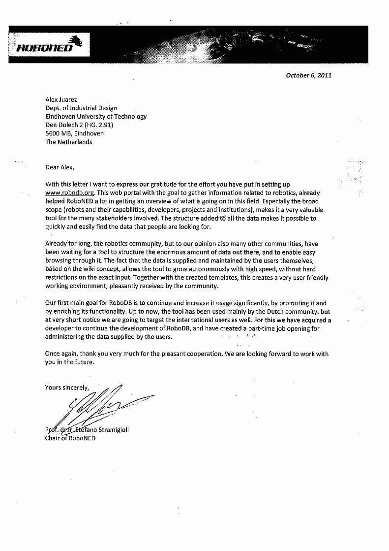
Appendix
BBuilt-in knowledge base glossary
Glossary of property definitions used in the knowledge engineering process (see Chapter 5).
Entity Type Meaning
Robot Class Class that contains entities representing robots, e.g.
AIBO, Roomba, iCat, etc.
Component Class Class that contains entities representing robot com-
ponents other than sensors, e.g. legs, arms, motors,
grippers, etc.
Sensor Class Class that contains entities representing robot sensors,
e.g. cameras, microphones, ultrasound, etc.
Robotics project Class Class that contains entities representing investigation
projects doing research on robotics, e.g. iCub, Meta-
verse1, Team DARE, etc.
Robotics technology Class Class that contains entities representing different
technologies developed by institutions represented in
RoboNed, e.g. machine vision, artificial intelligence,
etc.
Application area Class Class that contains entities representing areas of ap-
plication of the technologies developed by robotics re-
search projects, e.g. medical domain, care and cure,
etc.
Institution Class Class that contains entities representing institutions
from industry and academy that perform research in
robotics, e.g. TU Eindhoven, Philips, etc.
People Class Class that contains entities representing the people in-
volved in robotics research, e.g. robot creators and de-
velopers, project team leaders and coordinators, etc.
121
Appendix B. Built-in knowledge base glossary
uses robot Object
property
Defines a relationship indicating that a robotics project
uses a robot embodiment for research and devel-
opment work. Domain: Robotics project, Range:
Robot, inverse: is used in.
has coordinator Object
property
Defines a relationship indicating that a robotics project
has a person designated as coordinator or project
leader. Domain: Robotics project, Range: People,
inverse: is coordinator of.
has partner Object
property
Defines a relationship indicating that a robotics project
has an institution as a member of its consortium. Do-
main: Robotics project, Range: Institution, inverse:
is partner of.
has technology Object
property
Defines a relationship indicating that a robotics project
develops a robotics technology. Domain: Robotics
project, Range: Robotics technology, inverse: is tech-
nology of.
has component Object
property
Defines a relationship indicating that a robot embodi-
ment has a component as a part of it. Domain: Robot,
Range: Component, other properties: transitive.
has sensor Object
property
Defines a relationship indicating that a robot emb odi-
ment has a sensor as part of it. Domain: Robot,
Range: Sensor, other properties: transitive.
has partner Object
property
Defines a relationship indicating that a robotics project
has an institution as a member of its consortium. Do-
main: Robotics project, Range: Institution, inverse:
is partner of.
is connected to Object
property
Defines a relationship indicating two things are con-
nected to each other. Used mostly to relate compo-
nents and sensors to robots, but can also be used to
link any other type of entity. Domain: Thing, Range:
Thing, other properties: transitive, symmetric.
created by Object
property
Defines a relationship indicating the creator or a robot.
Domain: Robot, Range: People.
has country of origin Object
property
Indicates the country where a robot was developed, or
that is known to be the origin of the robot.. Domain:
Robot, Range: Thing.
has application area Object
property
Indicates the application fields for the robotics technol-
ogy developed in a robotics project. Domain: Robotics
project, Range: Application area, other properties:
transitive, inverse: is application area of.
has start date Data
property
Indicates the starting date of a robotics research
project. Used to indicate the lifespan of the project.
Domain: Robotics project, Range: date.
has end date Data
property
Indicates the end date of a robotics research project.
Used to indicate the lifespan of the project. Domain:
Robotics project, Range: date.
122
Appendix B. Built-in knowledge base glossary
has contact address Data
property
Indicates the an entity containing the contact ad-
dress in string format for a robotics project. Domain:
Robotics project, Range: string.
has contact phone Data
property
Indicates the contact phone to be used in a robotics
research project. Domain: Robotics project, Range:
string.
has website Data
property
Indicates the website of a robotics research project.
Domain: Robotics project, Range: anyURI.
number of compo-
nents
Data
property
Indicates the number of components (excluding sen-
sors) a robot embodiment has. Domain: Robot,
Range: integer.
number of sensors Data
property
Indicates the number of sensors (excluding sensors)
a robot embodiment has. Domain: Robot, Range:
integer.
123

Appendix
CXML schema definitions for MPEG-V data
structures
This appendix contains the XML schema definitions for the data structures submitted for
consideration to the MPEG-V standardization committee.
<schema xmlns=” h t t p : //www. w3 . o rg /2001/XMLSchema”
xm l n s : x s d=” h t t p : //www. w3 . o rg /2001/XMLSchema”
xm l n s : r d b=” h t t p : //www. robodb . o rg / o n t o l o g i e s /mpegv/ robotmpegv ”
ta rge tNamespace=” h t t p : //www. robodb . o rg / o n t o l o g i e s /mpegv/ robotmpegv ”
e l ementFo rmDe fau l t=” u n q u a l i f i e d ”
a t t r i b u t e F o rmDe f a u l t=” u n q u a l i f i e d ”>
<a n n o t a t i o n>
<documenta t i on xm l : l a n g=”en”>
Robot embodiment d e s c r i p t i o n example . For c o n s i d e r a t i o n o f
the MPEG−V s t a n d a r d i z a t i o n commitee .
</ documenta t i on>
</ a n n o t a t i o n>
< !−−##########################################Root e l ement d e f i n i t i o n
###########################################−−><e l ement name=” Robo tDe s c r i p t i o n ” t ype=” rdb :Embod imen tDes c r i p t i onType ”
>
<a n n o t a t i o n>
<documenta t i on xm l : l a n g=”en”>
Root node f o r the r obo t embodiment d e s c r i p t i o n . Each d e s c r i p t i o n
w i l l have f o u r s e c t i o n s a ) a s e c t i o n w i t h a g e n e r a l d e s c r i p t i o n
about the robot , b ) a s e c t i o n to d e s c r i b e the r obo t p a r t s and the
c o nn e c t i o n between them , c ) a s e c t i o n w i t h a d d i t i o n a l
i n f o rm a t i o n about the robot , e x p r e s s e d i n p r o p e r t i e s , and d ) a
s e c t i o n w i t h c a p a b i l i t y d e f i n i t i o n s .
125
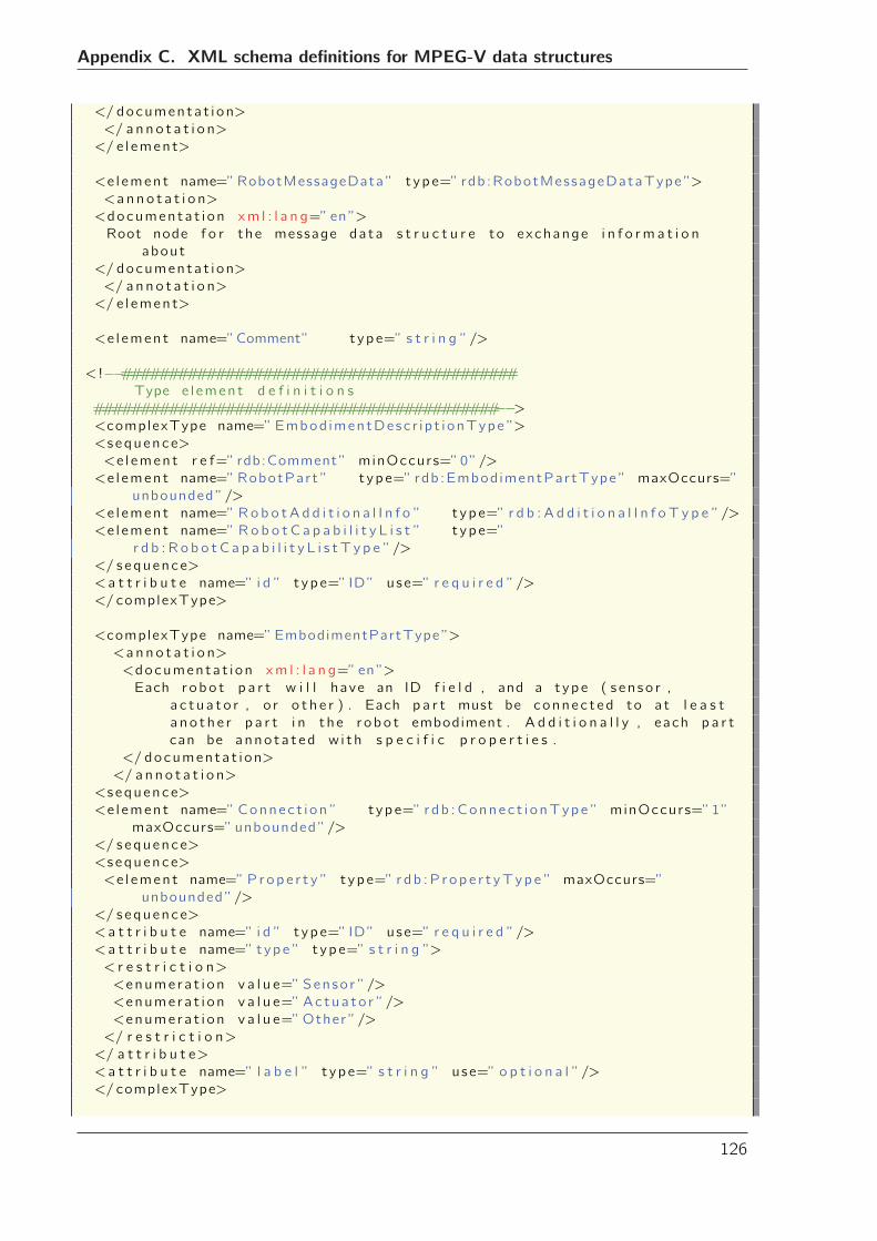
Appendix C. XML schema definitions for MPEG-V data structures
</ documenta t i on>
</ a n n o t a t i o n>
</ e l ement>
<e l ement name=”RobotMessageData ” t ype=” rdb:RobotMessageDataType ”>
<a n n o t a t i o n>
<documenta t i on xm l : l a n g=”en”>
Root node f o r the message data s t r u c t u r e to exchange i n f o rm a t i o n
about
</ documenta t i on>
</ a n n o t a t i o n>
</ e l ement>
<e l ement name=”Comment” t ype=” s t r i n g ”/>
< !−−##########################################Type e l ement d e f i n i t i o n s
###########################################−−><complexType name=”Embod imentDesc r i p t i onType ”>
<s equence>
<e l ement r e f=” rdb:Comment” minOccurs=”0”/>
<e l ement name=”RobotPart ” t ype=” rdb:Embod imentPartType ” maxOccurs=”
unbounded ”/>
<e l ement name=” Ro b o tA d d i t i o n a l I n f o ” t ype=” r d b : A d d i t i o n a l I n f o T y p e ”/>
<e l ement name=” R o b o t C a p a b i l i t y L i s t ” t ype=”
r d b : R o b o t C a p a b i l i t y L i s t T y p e ”/>
</ sequence>
<a t t r i b u t e name=” i d ” t ype=” ID” use=” r e q u i r e d ”/>
</ complexType>
<complexType name=”EmbodimentPartType”>
<a n n o t a t i o n>
<documenta t i on xm l : l a n g=”en”>
Each robo t p a r t w i l l have an ID f i e l d , and a t ype ( s en so r ,
a c t u a t o r , o r o t h e r ) . Each p a r t must be connec t ed to at l e a s t
a no t h e r p a r t i n the r obo t embodiment . A d d i t i o n a l l y , each p a r t
can be anno ta t ed w i t h s p e c i f i c p r o p e r t i e s .
</ documenta t i on>
</ a n n o t a t i o n>
<s equence>
<e l ement name=”Connec t i on ” t ype=” rdb :Connec t i onType ” minOccurs=”1”
maxOccurs=”unbounded ”/>
</ sequence>
<s equence>
<e l ement name=” P rop e r t y ” t ype=” r db :P r op e r t yTyp e ” maxOccurs=”
unbounded ”/>
</ sequence>
<a t t r i b u t e name=” i d ” t ype=” ID” use=” r e q u i r e d ”/>
<a t t r i b u t e name=” type ” t ype=” s t r i n g ”>
< r e s t r i c t i o n>
<enume ra t i on v a l u e=” Senso r ”/>
<enume ra t i on v a l u e=” Ac tua to r ”/>
<enume ra t i on v a l u e=”Other ”/>
</ r e s t r i c t i o n>
</ a t t r i b u t e>
<a t t r i b u t e name=” l a b e l ” t ype=” s t r i n g ” use=” o p t i o n a l ”/>
</ complexType>
126
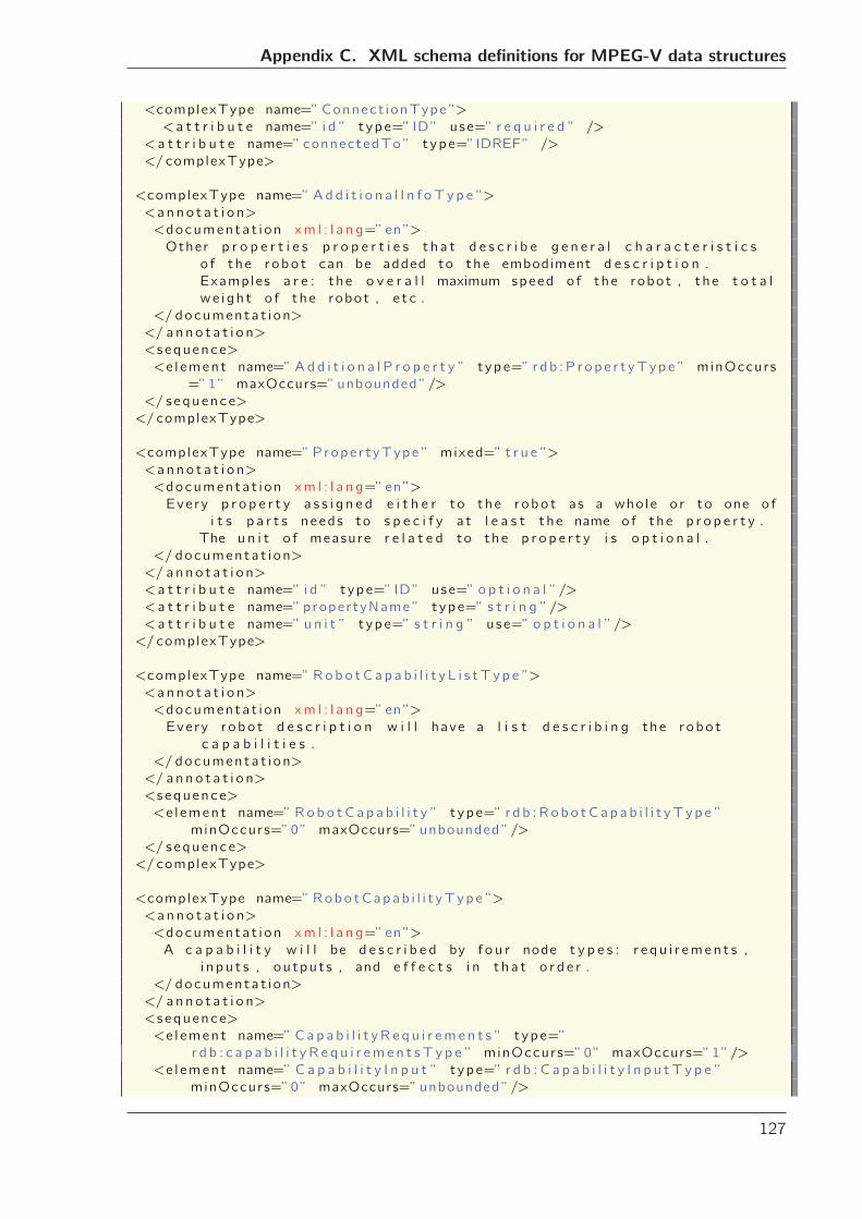
Appendix C. XML schema definitions for MPEG-V data structures
<complexType name=”Connect ionType ”>
<a t t r i b u t e name=” i d ” t ype=” ID” use=” r e q u i r e d ” />
<a t t r i b u t e name=” connectedTo ” t ype=”IDREF” />
</ complexType>
<complexType name=” Ad d i t i o n a l I n f oT y p e ”>
<a n n o t a t i o n>
<documenta t i on xm l : l a n g=”en”>
Other p r o p e r t i e s p r o p e r t i e s t h a t d e s c r i b e g e n e r a l c h a r a c t e r i s t i c s
o f the r obo t can be added to the embodiment d e s c r i p t i o n .
Examples a r e : the o v e r a l l maximum speed o f the robot , the t o t a l
we i gh t o f the robot , e t c .
</ documenta t i on>
</ a n n o t a t i o n>
<s equence>
<e l ement name=” A d d i t i o n a l P r o p e r t y ” t ype=” r db :P r op e r t yTyp e ” minOccurs
=”1” maxOccurs=”unbounded ”/>
</ sequence>
</ complexType>
<complexType name=”Prope r t yType ” mixed=” t r u e ”>
<a n n o t a t i o n>
<documenta t i on xm l : l a n g=”en”>
Eve ry p r o p e r t y a s s i g n e d e i t h e r to the r obo t as a who le o r to one o f
i t s p a r t s needs to s p e c i f y a t l e a s t the name o f the p r o p e r t y .
The u n i t o f measure r e l a t e d to the p r o p e r t y i s o p t i o n a l .
</ documenta t i on>
</ a n n o t a t i o n>
<a t t r i b u t e name=” i d ” t ype=” ID” use=” o p t i o n a l ”/>
<a t t r i b u t e name=” propertyName ” t ype=” s t r i n g ”/>
<a t t r i b u t e name=” u n i t ” t ype=” s t r i n g ” use=” o p t i o n a l ”/>
</ complexType>
<complexType name=” Rob o tC a p a b i l i t y L i s tT y p e ”>
<a n n o t a t i o n>
<documenta t i on xm l : l a n g=”en”>
Eve ry r obo t d e s c r i p t i o n w i l l have a l i s t d e s c r i b i n g the r obo t
c a p a b i l i t i e s .
</ documenta t i on>
</ a n n o t a t i o n>
<s equence>
<e l ement name=” Rob o tC a p a b i l i t y ” t ype=” r d b :Ro b o tC a p a b i l i t yT y p e ”
minOccurs=”0” maxOccurs=”unbounded ”/>
</ sequence>
</ complexType>
<complexType name=” Robo tCapab i l i t yTyp e ”>
<a n n o t a t i o n>
<documenta t i on xm l : l a n g=”en”>
A c a p a b i l i t y w i l l be d e s c r i b e d by f o u r node t y p e s : r e q u i r emen t s ,
i n p u t s , ou tput s , and e f f e c t s i n t h a t o r d e r .
</ documenta t i on>
</ a n n o t a t i o n>
<s equence>
<e l ement name=” Ca p a b i l i t y R e q u i r em e n t s ” t ype=”
r d b : c a p a b i l i t y R e q u i r em e n t sT y p e ” minOccurs=”0” maxOccurs=”1”/>
<e l ement name=” C a p a b i l i t y I n p u t ” t ype=” r d b : C a p a b i l i t y I n p u t T y p e ”
minOccurs=”0” maxOccurs=”unbounded ”/>
127
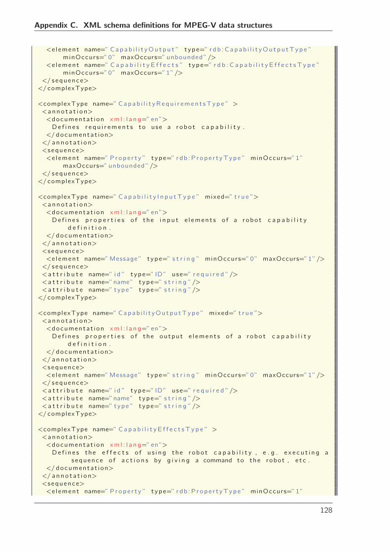
Appendix C. XML schema definitions for MPEG-V data structures
<e l ement name=” Ca p a b i l i t yOu t p u t ” t ype=” r d b :C a p a b i l i t yOu t p u tT y p e ”
minOccurs=”0” maxOccurs=”unbounded ”/>
<e l ement name=” C a p a b i l i t y E f f e c t s ” t ype=” r d b : C a p a b i l i t y E f f e c t s T y p e ”
minOccurs=”0” maxOccurs=”1”/>
</ sequence>
</ complexType>
<complexType name=” Cap a b i l i t yR e q u i r emen t sT y p e ” >
<a n n o t a t i o n>
<documenta t i on xm l : l a n g=”en”>
De f i n e s r e q u i r eme n t s to use a r obo t c a p a b i l i t y .
</ documenta t i on>
</ a n n o t a t i o n>
<s equence>
<e l ement name=” P rop e r t y ” t ype=” r db :P r op e r t yTyp e ” minOccurs=”1”
maxOccurs=”unbounded ”/>
</ sequence>
</ complexType>
<complexType name=” C a p a b i l i t y I n p u tT y p e ” mixed=” t r u e ”>
<a n n o t a t i o n>
<documenta t i on xm l : l a n g=”en”>
De f i n e s p r o p e r t i e s o f the i n p u t e l emen t s o f a r obo t c a p a b i l i t y
d e f i n i t i o n .
</ documenta t i on>
</ a n n o t a t i o n>
<s equence>
<e l ement name=”Message” t ype=” s t r i n g ” minOccurs=”0” maxOccurs=”1”/>
</ sequence>
<a t t r i b u t e name=” i d ” t ype=” ID” use=” r e q u i r e d ”/>
<a t t r i b u t e name=”name” t ype=” s t r i n g ”/>
<a t t r i b u t e name=” type ” t ype=” s t r i n g ”/>
</ complexType>
<complexType name=” Capab i l i t yOu t pu tTyp e ” mixed=” t r u e ”>
<a n n o t a t i o n>
<documenta t i on xm l : l a n g=”en”>
De f i n e s p r o p e r t i e s o f the ou tpu t e l emen t s o f a r obo t c a p a b i l i t y
d e f i n i t i o n .
</ documenta t i on>
</ a n n o t a t i o n>
<s equence>
<e l ement name=”Message” t ype=” s t r i n g ” minOccurs=”0” maxOccurs=”1”/>
</ sequence>
<a t t r i b u t e name=” i d ” t ype=” ID” use=” r e q u i r e d ”/>
<a t t r i b u t e name=”name” t ype=” s t r i n g ”/>
<a t t r i b u t e name=” type ” t ype=” s t r i n g ”/>
</ complexType>
<complexType name=” C a p a b i l i t y E f f e c t s T y p e ” >
<a n n o t a t i o n>
<documenta t i on xm l : l a n g=”en”>
De f i n e s the e f f e c t s o f u s i n g the r obo t c a p a b i l i t y , e . g . e x e c u t i n g a
sequence o f a c t i o n s by g i v i n g a command to the robot , e t c .
</ documenta t i on>
</ a n n o t a t i o n>
<s equence>
<e l ement name=” P rop e r t y ” t ype=” r db :P r op e r t yTyp e ” minOccurs=”1”
128
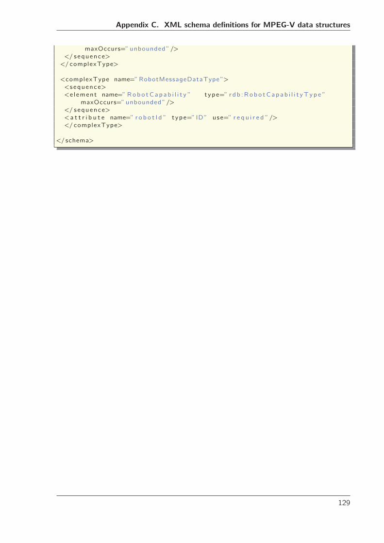
Appendix C. XML schema definitions for MPEG-V data structures
maxOccurs=”unbounded ”/>
</ sequence>
</ complexType>
<complexType name=”RobotMessageDataType ”>
<s equence>
<e l ement name=” Rob o tC a p a b i l i t y ” t ype=” r d b :Ro b o tC a p a b i l i t yT y p e ”
maxOccurs=”unbounded ”/>
</ sequence>
<a t t r i b u t e name=” r o b o t I d ” t ype=” ID” use=” r e q u i r e d ”/>
</ complexType>
</ schema>
129

Appendix
DPAC4 class diagram
This appendix presents the concrete class diagram of the implementation of the PAC4
system introduced in Chapter 6.
131
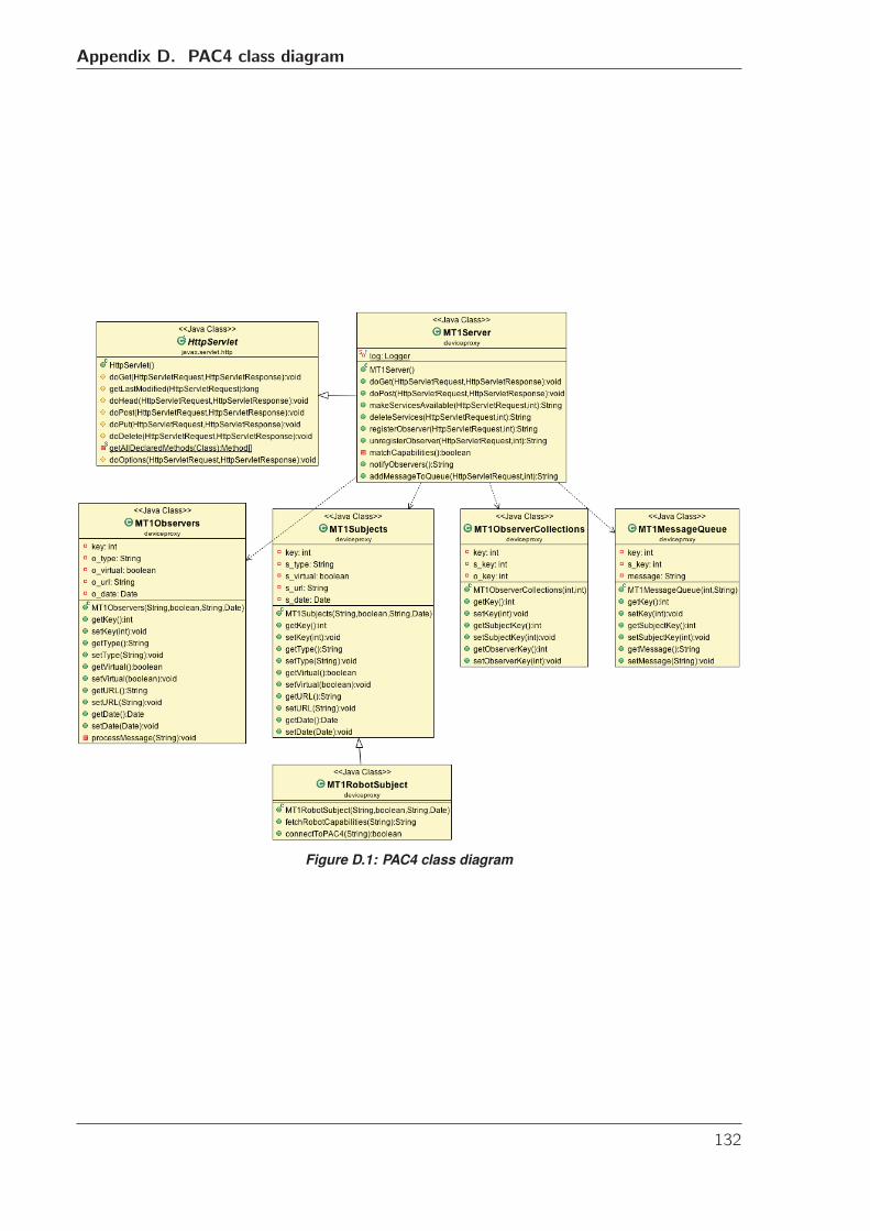
Appendix D. PAC4 class diagram
Figure D.1: PAC4 class diagram
132
Appendix
EPAC4 User Evaluation Questionnaires
This appendix presents the original IPO-Social Presence Questionnaire and the open-ended
questions administered to the participants in the user experiment of Chapter 6.
133
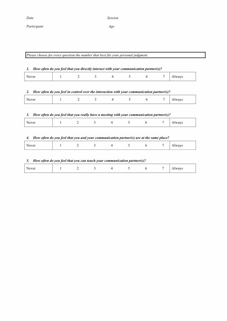
Date Session Participant Age
Please choose for every question the number that best fits your personal judgment.
1. How often do you feel that you directly interact with your communication partner(s)?
Never 1 2 3 4 5 6 7 Always
2. How often do you feel in control over the interaction with your communication partner(s)?
Never 1 2 3 4 5 6 7 Always
3. How often do you feel that you really have a meeting with your communication partner(s)?
Never 1 2 3 4 5 6 7 Always
4. How often do you feel that you and your communication partner(s) are at the same place?
Never 1 2 3 4 5 6 7 Always
5. How often do you feel that you can touch your communication partner(s)?
Never 1 2 3 4 5 6 7 Always
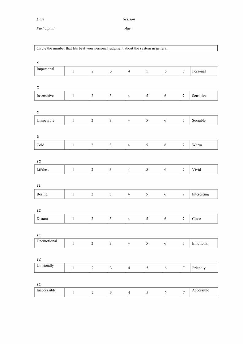
Date Session Participant Age
Circle the number that fits best your personal judgment about the system in general
6. Impersonal 1 2 3 4 5 6 7 Personal
7.
Insensitive 1 2 3 4 5 6 7 Sensitive
8.
Unsociable 1 2 3 4 5 6 7 Sociable
9.
Cold 1 2 3 4 5 6 7 Warm
10.
Lifeless 1 2 3 4 5 6 7 Vivid
11.
Boring 1 2 3 4 5 6 7 Interesting
12.
Distant 1 2 3 4 5 6 7 Close
13. Unemotional 1 2 3 4 5 6 7 Emotional
14. Unfriendly 1 2 3 4 5 6 7 Friendly
15. Inaccessible 1 2 3 4 5 6 7 Accessible
���������� �� ����������� ��� ����������������������������� ������
���������������������������������� ���� ������������������� ��
������� ������ ��� ������ ������������������ ����� ������� ������
���������������� �������� ���������������� ���������
�
���� ����������� ����� ��������������!�
�
�
�
�
"�� ������������� ������������ ����� �� �������� ��� �����������������
�������� ��� ��������!� ��!�
�
�
�
�
�
#�� ������������� ������������ ������ �� ����������� ������� ���������
� �������� ��� ��������������������� �������!�
�
�
�
�
$�� ������������� ������������ ������ �� �������������������� ����
����� ��������� ��������������!� ��!�
Appendix
FList of publications
Publications of the work described in this document
1. Juarez, A., Bartneck, C., & Feijs, L. Studying Virtual Worlds as Medium for Telepresence
Robots. In Proceedings of the 7th. International Conference on Human Robot Interaction
(HRI), pp. 230256, March 2012.
2. Juarez, A., Hu, J., & Feijs, L. RoboDB: an application of Semantic Web technologies
to robotics. Semantic Web Challenge 2011. International Semantic Web Conference 2011,
October 2011.
3. Juarez, A., Bartneck, C., & Feijs, L. Using Semantic Web Technologies to Describe
Robotic Embodiments. In Proceedings of the 6th. International Conference on Human-
Robot Interaction (HRI), pp. 425432, March 2011.
4. Juarez, A., Bartneck, C., & Feijs, L.. On the Creation of Standards for Interaction
Between Robots and Virtual Worlds. Journal of Virtual Worlds Research, Vol. 2Number 3,
October 2009
Other related publications
5. Juarez, A., Schonenberg, W. & Bartneck, C.. Implementing a Low-cost CAVE system
using the CryEngine2. Journal of Entertainment Computing, Vol. 1Number 3-4, pp. 157-
164, October 2010.
6. Nakevska, M., Juarez, A. & Hu, J. CryVE: Modding the CryEngine2 to create a CAVE
system. To be published as a book chapter inGame Mod Design Theory and Criticism.
ETC Press.
137

Appendix
GSummary
Semantic Web for RobotsAn application for interoperability between virtual worlds
and real robots
The topic of this PhD project is in the context of cross-reality, a term that defines
mixed reality environments that tunnel dense real-world data acquired through the use of
sensor/actuator device networks into virtual worlds. It is part of the ongoing academia and
industry efforts to achieve interoperability between virtual and real devices and services.
The research hypothesis can be formulated in short as follows:
Interoperability between virtual worlds and real robots can be achieved by apply-
ing state of the art (semantic) web technologies in a proper way. These tech-
nologies should handle the heterogeneity and high reconfigurability of robotic
systems, while at the same time create information and knowledge about their
capabilities, in such a way that this knowledge can be understood and used not
only by current virtual world software but also by other web agents. Virtual
worlds (and the virtual world’s user experience) can be enriched by augmenting
it with the abilities of real robots in remote locations.
The focus of this thesis is on three aspects: a) it focuses on the mechanisms necessary
to make information about robots available to virtual worlds, b) it focuses on the creation,
maintenance and use of knowledge about robot capabilities to enhance the virtual world
functionality, and c) it focuses on the virtual world’s user experience with such system in a
139
Appendix G. Summary
remote communication scenario.
To this effect, two systems have been developed: RoboDB a collaborative, community-
oriented web system based on Semantic Web technologies that gathers information about
robots and their capabilities in a structured way, and PAC4 a web service discovery system
that utilizes the knowledge created by RoboDB to connect virtual worlds to real robots.
Finally a study was conducted on the virtual world user’s perception of presence when using
PAC4 to interact with the real robot in a remote communication scenario.
140
Appendix
HCurriculum Vitae
Alex Juarez was born in San Salvador, El Salvador, on July 31st, 1981. From 1999 to 2004
he studied a ‘Bachelor in Computer Science’ at Universidad Centroamericana (UCA). As
he finished his studies, he began working as Project Coordinator in the Business Intelligence
Team at TACA International Airlines. However, he had already set up a goal for himself: to
continue his studies abroad specializing in High-Tech systems. In October 2005 he started
studies at the ‘Masters in Autonomous Systems’ at FH Bonn-Rhein-Sieg, Sankt Augustin,
Germany. During the course of these studies he obtained knowledge and experience in
robotics, distributed systems, and software development for autonomous systems, among
others. His masters thesis focused on robotics and artificial intelligence: he created a com-
putational model of robotic surprise to automatically initiate episodes of machine learning in
unstructured environments. This work was an important contribution to the successful Eu-
ropean research project XPERO: Robot Learning by Experimentation. He graduated from
the Masters program on January 2008. At the end of that year, he initiated work toward
obtaining a PHD degree at the Department of Industrial Design, Eindhoven University of
Technology. The results of this work are presented in this technological design disserta-
tion. Since January 2012, he is employed as a Design Engineer at ASML Headquarters,
Veldhoven, Netherlands.
141