Instructions for replacement with Σ-7 series
84
Section-2, Technology Promotion Department, Motion Control Division, YASKAWA ELECTRIC CORPORATION Instructions for replacement with Σ-7 series Replacement target Motor: Σ-II ( SGMAH, SGMPH, SGMGH, SGMSH ) SERVOPACK : Σ-II AC power input Type (SGDM, SGDH, SGDJ) Table of contents 1 . Precautions concerning use .............................................................................................................. 3 1.1 . Precautions concerning use ................................................................................................................. 3 1.2 . Σ-7/Σ-II, MP3300/MP2000 compatibility table ...................................................................................... 6 1.3 . Check sheet for replacement of Σ-II by Σ-7 ........................................................................................... 8 1.4 . Concept of replacement ..................................................................................................................... 12 1.5 . List of replacements .......................................................................................................................... 13 2 . Motor ......................................................................................................................................... 25 2.1 . Model compatibility table ................................................................................................................... 25 1 Without speed reducer........................................................................................................................25 2 With speed reducer............................................................................................................................32 2.2 . Characteristics table .......................................................................................................................... 37 ( 1 ) Without speed reducer.....................................................................................................................37 2 With speed reducer.............................................................................................................................41 2.3 . Mounting dimension ......................................................................................................................... 46 ( 1 ) Without speed reducer (standard) ...................................................................................................46 ( 2 ) With general speed reducer..............................................................................................................51 3 With precision speed reducer...............................................................................................................54 3 . SERVOPACK ................................................................................................................................. 58 3.1 . Models comparison table ................................................................................................................... 58 3.2 . Terminal compatibility table ............................................................................................................... 58 14H-011 1/84
Transcript of Instructions for replacement with Σ-7 series
Section-2, Technology Promotion Department,
Motion Control Division,
YASKAWA ELECTRIC CORPORATION
Instructions for replacement withΣ-7 series
Replacement target
Motor: Σ-II ( SGMAH, SGMPH, SGMGH, SGMSH ) SERVOPACK : Σ-II AC power input Type (SGDM, SGDH, SGDJ)
Table of contents
1 . Precautions concerning use .............................................................................................................. 3
1.1 . Precautions concerning use ................................................................................................................. 3
1.2 . Σ-7/Σ-II, MP3300/MP2000 compatibility table ...................................................................................... 6
1.3 . Check sheet for replacement of Σ-II by Σ-7 ........................................................................................... 8
1.4 . Concept of replacement ..................................................................................................................... 12
1.5 . List of replacements .......................................................................................................................... 13
2 . Motor ......................................................................................................................................... 25
2.1 . Model compatibility table ................................................................................................................... 25
1 Without speed reducer........................................................................................................................25
2 With speed reducer............................................................................................................................32
2.2 . Characteristics table .......................................................................................................................... 37
(1) Without speed reducer.....................................................................................................................37
2 With speed reducer.............................................................................................................................41
2.3 . Mounting dimension ......................................................................................................................... 46
(1) Without speed reducer (standard) ...................................................................................................46
(2) With general speed reducer..............................................................................................................51
3 With precision speed reducer...............................................................................................................54
3 . SERVOPACK ................................................................................................................................. 58
3.1 . Models comparison table ................................................................................................................... 58
3.2 . Terminal compatibility table ............................................................................................................... 58 14H-011 1/84
(1) Main circuit terminal........................................................................................................................58
2 Control circuit terminal ......................................................................................................................60
3.3 . Mounting dimension .......................................................................................................................... 63
3.4 . Precautions at the time of mounting control panel ............................................................................... 69
4 . Cable and peripheral equipment .................................................................................................... 70
5 . User constant conversion .............................................................................................................. 77
5.1 . Parameter convertor ......................................................................................................................... 77
5.2 . Setting of electronic gear ratio (when using in position control mode) ................................................. 80
14H-011 2/84
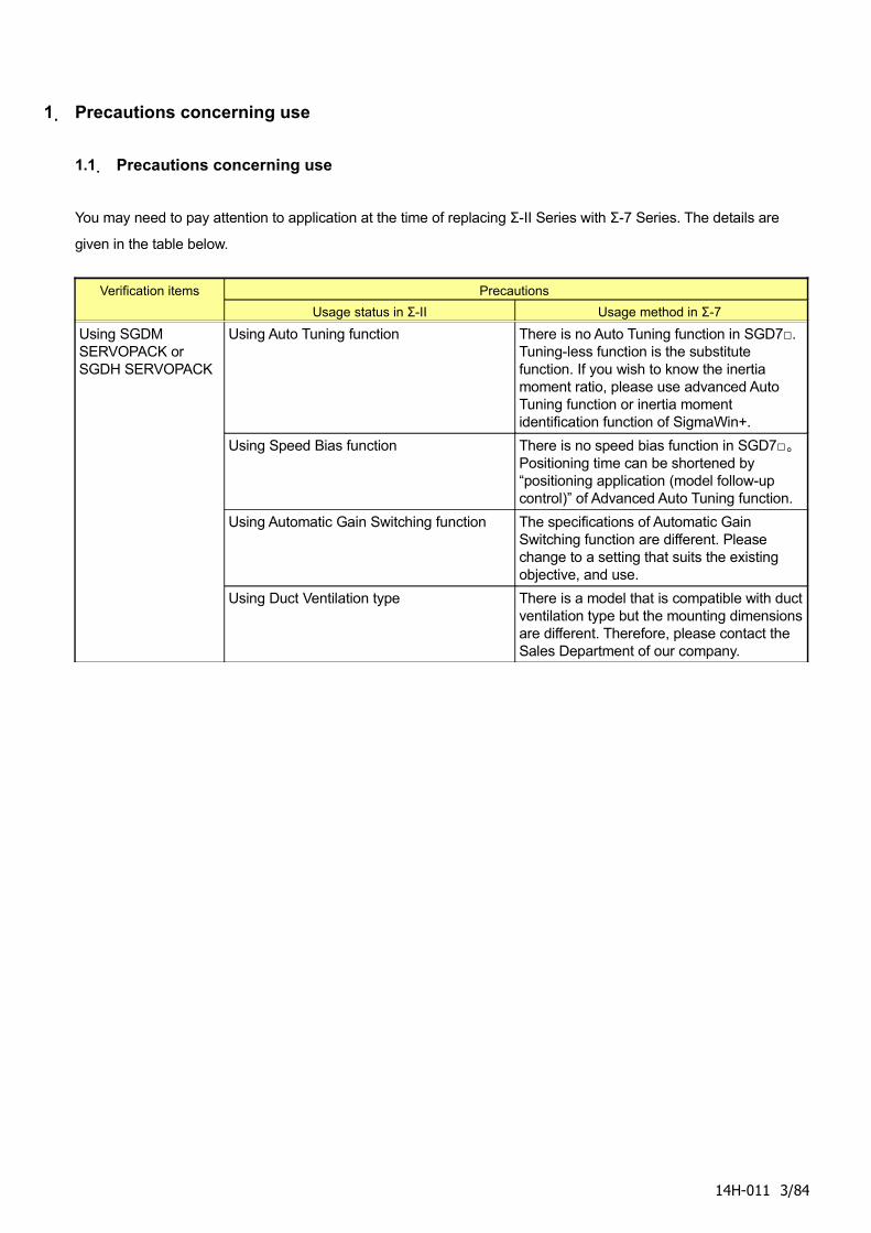
1. Precautions concerning use
1.1. Precautions concerning use
You may need to pay attention to application at the time of replacing Σ-II Series with Σ-7 Series. The details are
given in the table below.
Verification items Precautions
Usage status in Σ-II Usage method in Σ-7
Using SGDM SERVOPACK or SGDH SERVOPACK
Using Auto Tuning function There is no Auto Tuning function in SGD7□. Tuning-less function is the substitute function. If you wish to know the inertia moment ratio, please use advanced Auto Tuning function or inertia moment identification function of SigmaWin+.
Using Speed Bias function There is no speed bias function in SGD7□。 Positioning time can be shortened by “positioning application (model follow-up control)” of Advanced Auto Tuning function.
Using Automatic Gain Switching function The specifications of Automatic Gain Switching function are different. Please change to a setting that suits the existing objective, and use.
Using Duct Ventilation type There is a model that is compatible with duct ventilation type but the mounting dimensions are different. Therefore, please contact the Sales Department of our company.
14H-011 3/84
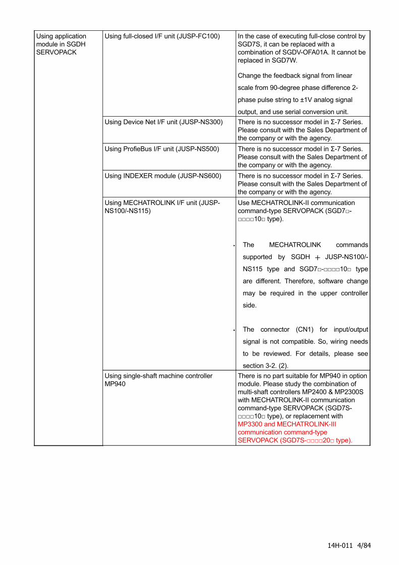
Using application module in SGDH SERVOPACK
Using full-closed I/F unit (JUSP-FC100) In the case of executing full-close control by SGD7S, it can be replaced with a combination of SGDV-OFA01A. It cannot be replaced in SGD7W.
Change the feedback signal from linear
scale from 90-degree phase difference 2-
phase pulse string to ±1V analog signal
output, and use serial conversion unit.
Using Device Net I/F unit (JUSP-NS300) There is no successor model in Σ-7 Series. Please consult with the Sales Department of the company or with the agency.
Using ProfieBus I/F unit (JUSP-NS500) There is no successor model in Σ-7 Series. Please consult with the Sales Department of the company or with the agency.
Using INDEXER module (JUSP-NS600) There is no successor model in Σ-7 Series. Please consult with the Sales Department of the company or with the agency.
Using MECHATROLINK I/F unit (JUSP-NS100/-NS115)
Use MECHATROLINK-II communication command-type SERVOPACK (SGD7□-□□□□10□ type).
・ The MECHATROLINK commands
supported by SGDH + JUSP-NS100/-
NS115 type and SGD7□-□□□□10□ type
are different. Therefore, software change
may be required in the upper controller
side.
・ The connector (CN1) for input/output
signal is not compatible. So, wiring needs
to be reviewed. For details, please see
section 3-2. (2).
Using single-shaft machine controller MP940
There is no part suitable for MP940 in option module. Please study the combination of multi-shaft controllers MP2400 & MP2300S with MECHATROLINK-II communication command-type SERVOPACK (SGD7S-□□□□10□ type), or replacement with MP3300 and MECHATROLINK-III communication command-type SERVOPACK (SGD7S-□□□□20□ type).
14H-011 4/84
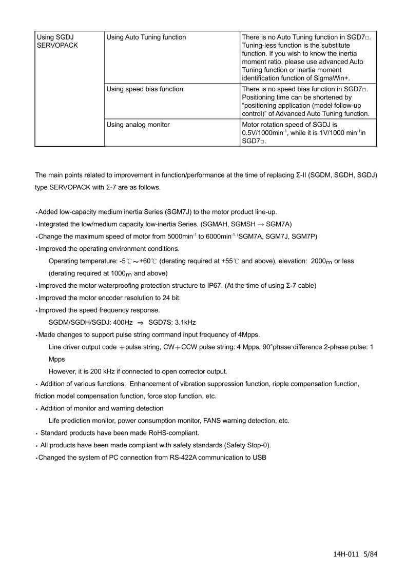
Using SGDJ SERVOPACK
Using Auto Tuning function There is no Auto Tuning function in SGD7□. Tuning-less function is the substitute function. If you wish to know the inertia moment ratio, please use advanced Auto Tuning function or inertia moment identification function of SigmaWin+.
Using speed bias function There is no speed bias function in SGD7□. Positioning time can be shortened by “positioning application (model follow-up control)” of Advanced Auto Tuning function.
Using analog monitor Motor rotation speed of SGDJ is 0.5V/1000min-1, while it is 1V/1000 min-1in SGD7□.
The main points related to improvement in function/performance at the time of replacing Σ-II (SGDM, SGDH, SGDJ)
type SERVOPACK with Σ-7 are as follows.
・Added low-capacity medium inertia Series (SGM7J) to the motor product line-up.
・Integrated the low/medium capacity low-inertia Series. (SGMAH, SGMSH → SGM7A)
・Change the maximum speed of motor from 5000min-1 to 6000min-1. (SGM7A, SGM7J, SGM7P)
・Improved the operating environment conditions.
Operating temperature: -5℃~+60℃ (derating required at +55℃ and above), elevation: 2000m or less
(derating required at 1000m and above)
・Improved the motor waterproofing protection structure to IP67. (At the time of using Σ-7 cable)
・Improved the motor encoder resolution to 24 bit.
・Improved the speed frequency response.
SGDM/SGDH/SGDJ: 400Hz ⇒ SGD7S: 3.1kHz
・Made changes to support pulse string command input frequency of 4Mpps.
Line driver output code +pulse string, CW+CCW pulse string: 4 Mpps, 90°phase difference 2-phase pulse: 1
Mpps
However, it is 200 kHz if connected to open corrector output.
・ Addition of various functions: Enhancement of vibration suppression function, ripple compensation function,
friction model compensation function, force stop function, etc.
・ Addition of monitor and warning detection
Life prediction monitor, power consumption monitor, FANS warning detection, etc.
・ Standard products have been made RoHS-compliant.
・ All products have been made compliant with safety standards (Safety Stop-0).
・Changed the system of PC connection from RS-422A communication to USB
14H-011 5/84
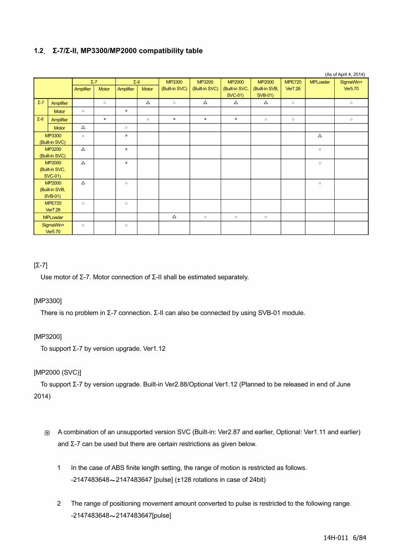
1.2. Σ-7/Σ-II, MP3300/MP2000 compatibility table
(As of April 4, 2014)
Σ-7 Σ-II
Amplifier Motor Amplifier Motor
MP3300
(Built-in SVC)
MP3200
(Built-in SVC)
MP2000
(Built-in SVC,
SVC-01)
MP2000
(Built-in SVB,
SVB-01)
MPE720
Ver7.26
MPLoader SigmaWin+
Ver5.70
Σ-7 Amplifier ○ △ ○ △ △ △ ○ ○
Motor ○ ×
Σ-II Amplifier × ○ × × × ○ ○ ○
Motor △ ○
MP3300
(Built-in SVC)
○ × △
MP3200
(Built-in SVC)
△ × ○
MP2000
(Built-in SVC,
SVC-01)
△ × ○
MP2000
(Built-in SVB,
SVB-01)
△ ○ ○
MPE720
Ver7.26
○ ○
MPLoader △ ○ ○ ○
SigmaWin+
Ver5.70
○ ○
[Σ-7]
Use motor of Σ-7. Motor connection of Σ-II shall be estimated separately.
[MP3300]
There is no problem in Σ-7 connection. Σ-II can also be connected by using SVB-01 module.
[MP3200]
To support Σ-7 by version upgrade. Ver1.12
[MP2000 (SVC)]
To support Σ-7 by version upgrade. Built-in Ver2.88/Optional Ver1.12 (Planned to be released in end of June
2014)
※ A combination of an unsupported version SVC (Built-in: Ver2.87 and earlier, Optional: Ver1.11 and earlier)
and Σ-7 can be used but there are certain restrictions as given below.
1 In the case of ABS finite length setting, the range of motion is restricted as follows.
-2147483648~2147483647 [pulse] (±128 rotations in case of 24bit)
2 The range of positioning movement amount converted to pulse is restricted to the following range.
-2147483648~2147483647[pulse]
14H-011 6/84
3 The reported feedback speed is an invalid value according to the relationship between high-speed
scan setting and operation speed.
[MP2000 (SVB)]
To support Σ-7 by version upgrade. Built-in: Ver2.89/Optional: Ver1.33 (Planned to be released in end of
September 2014)
※ Combination of unsupported version SVB (Built-in: Ver2.88 and earlier versions, Optional: Ver1.32 and
earlier versions) and Σ-7 can be used by assigning as Wild CardServo.
However, set the electronic gear ratio in Servo so that the command resolution is 1 command unit
16pulse. Also, there are restrictions on usage method in the case of Wild Card Servo setting, such as≧
restriction on usable motion command and inability to use parameter automatic reflection function.
[MPE720]
MP3300 and Σ-7 will be supported by version upgrade.
SVC will be supported by Ver7.27 for Σ-7S, and Σ-7W will be supported by version upgrade Ver7.28 (Planned to
be released in June 2014), while support for SVB is being worked out (planned to be supported in Ver. 7.29).
[MPLoader]
MP3300 will be supported by version upgrade. Ver4.02 (Planned to be released at the end of May in 2014)
[SigmaWin+]
To support Σ-7 by version upgrade. Ver5.70
14H-011 7/84
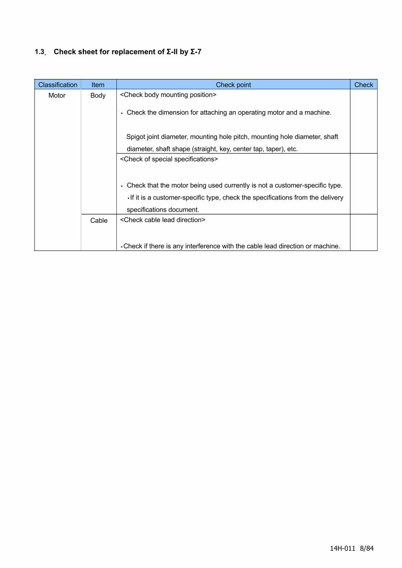
1.3. Check sheet for replacement of Σ-II by Σ-7
Classification Item Check point Check
Motor Body <Check body mounting position>
・ Check the dimension for attaching an operating motor and a machine.
Spigot joint diameter, mounting hole pitch, mounting hole diameter, shaft
diameter, shaft shape (straight, key, center tap, taper), etc.
<Check of special specifications>
・ Check that the motor being used currently is not a customer-specific type.
・If it is a customer-specific type, check the specifications from the delivery
specifications document.
Cable <Check cable lead direction>
・Check if there is any interference with the cable lead direction or machine.
14H-011 8/84
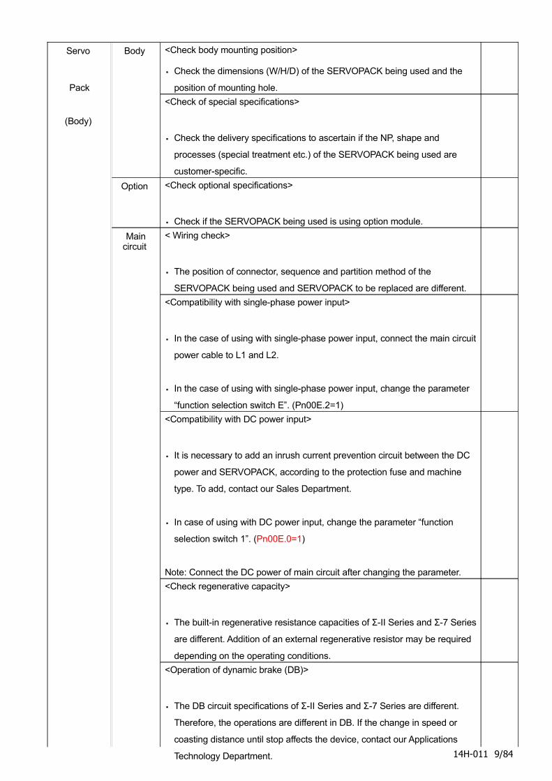
Servo
Pack
(Body)
Body <Check body mounting position>
・ Check the dimensions (W/H/D) of the SERVOPACK being used and the
position of mounting hole.
<Check of special specifications>
・ Check the delivery specifications to ascertain if the NP, shape and
processes (special treatment etc.) of the SERVOPACK being used are
customer-specific.
Option <Check optional specifications>
・ Check if the SERVOPACK being used is using option module.
Main circuit
< Wiring check>
・ The position of connector, sequence and partition method of the
SERVOPACK being used and SERVOPACK to be replaced are different.
<Compatibility with single-phase power input>
・ In the case of using with single-phase power input, connect the main circuit
power cable to L1 and L2.
・ In the case of using with single-phase power input, change the parameter
“function selection switch E”. (Pn00E.2=1)
<Compatibility with DC power input>
・ It is necessary to add an inrush current prevention circuit between the DC
power and SERVOPACK, according to the protection fuse and machine
type. To add, contact our Sales Department.
・ In case of using with DC power input, change the parameter “function
selection switch 1”. (Pn00E.0=1)
Note: Connect the DC power of main circuit after changing the parameter.
<Check regenerative capacity>
・ The built-in regenerative resistance capacities of Σ-II Series and Σ-7 Series
are different. Addition of an external regenerative resistor may be required
depending on the operating conditions.
<Operation of dynamic brake (DB)>
・ The DB circuit specifications of Σ-II Series and Σ-7 Series are different.
Therefore, the operations are different in DB. If the change in speed or
coasting distance until stop affects the device, contact our Applications
Technology Department. 14H-011 9/84

14H-011 10/84
Classification Item Check point Check
Servo
Pack
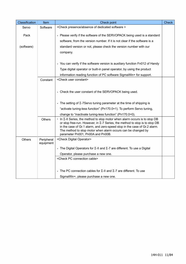
(software)
Software <Check presence/absence of dedicated software >
・ Please verify if the software of the SERVOPACK being used is a standard
software, from the version number. If it is not clear if the software is a
standard version or not, please check the version number with our
company.
・ You can verify if the software version is auxiliary function Fn012 of Handy
Type digital operator or built-in panel operator, by using the product
information reading function of PC software SigmaWin+ for support.
Constant <Check user constant>
・ Check the user constant of the SERVOPACK being used.
・ The setting of Σ-7Servo tuning parameter at the time of shipping is
“activate tuning-less function” (Pn170.0=1). To perform Servo tuning,
change to “inactivate tuning-less function” (Pn170.0=0).
Others ・ In Σ-II Series, the method to stop motor when alarm occurs is to stop DB or stop free-run. However, in Σ-7 Series, the method to stop is to stop DB in the case of Gr.1 alarm, and zero-speed stop in the case of Gr.2 alarm. The method to stop motor when alarm occurs can be changed by parameter Pn001, Pn00A and Pn00B.
Others Peripheral equipment
<Check Digital Operator>
・ The Digital Operators for Σ-II and Σ-7 are different. To use a Digital
Operator, please purchase a new one.
<Check PC connection cable>
・ The PC connection cables for Σ-II and Σ-7 are different. To use
SigmaWin+, please purchase a new one.
14H-011 11/84
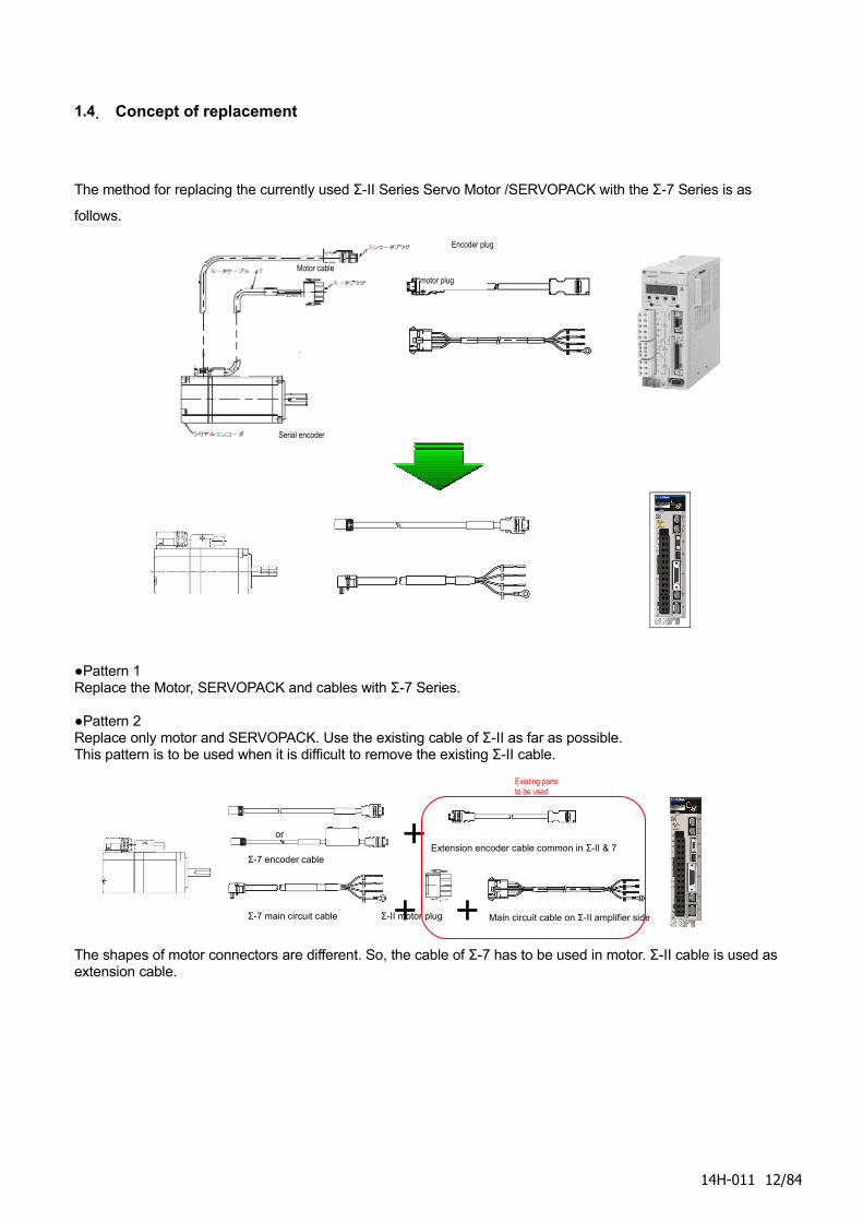
1.4. Concept of replacement
The method for replacing the currently used Σ-II Series Servo Motor /SERVOPACK with the Σ-7 Series is as
follows.
●Pattern 1Replace the Motor, SERVOPACK and cables with Σ-7 Series.
●Pattern 2Replace only motor and SERVOPACK. Use the existing cable of Σ-II as far as possible.This pattern is to be used when it is difficult to remove the existing Σ-II cable.
The shapes of motor connectors are different. So, the cable of Σ-7 has to be used in motor. Σ-II cable is used as extension cable.
14H-011 12/84
or
+
+
+Σ-7 main circuit cable
Extension encoder cable common in Σ-II & 7
Main circuit cable on Σ-II amplifier sideΣ-II motor plug
Σ-7 encoder cable
Existing parts to be used
Motor cable
Encoder plug
motor plug
Serial encoder
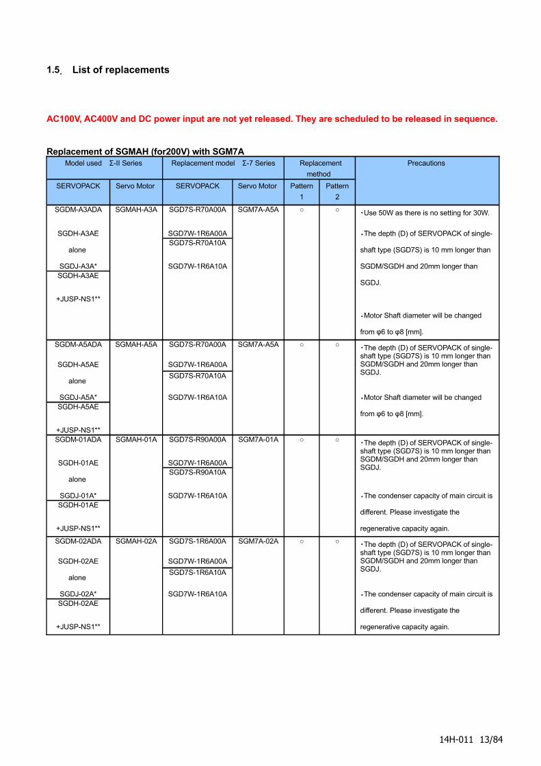
1.5. List of replacements
AC100V, AC400V and DC power input are not yet released. They are scheduled to be released in sequence.
Replacement of SGMAH (for200V) with SGM7AModel used Σ-II Series Replacement model Σ-7 Series Replacement
method
SERVOPACK Servo Motor SERVOPACK Servo Motor Pattern
1
Pattern
2
Precautions
SGDM-A3ADA
SGDH-A3AE
alone
SGDJ-A3A*SGDH-A3AE
+JUSP-NS1**
SGMAH-A3A SGD7S-R70A00A
SGD7W-1R6A00ASGD7S-R70A10A
SGD7W-1R6A10A
SGM7A-A5A ○ ○ ・Use 50W as there is no setting for 30W.
・The depth (D) of SERVOPACK of single-
shaft type (SGD7S) is 10 mm longer than
SGDM/SGDH and 20mm longer than
SGDJ.
・Motor Shaft diameter will be changed
from φ6 to φ8 [mm].
SGDM-A5ADA
SGDH-A5AE
alone
SGDJ-A5A*SGDH-A5AE
+JUSP-NS1**
SGMAH-A5A SGD7S-R70A00A
SGD7W-1R6A00A
SGD7S-R70A10A
SGD7W-1R6A10A
SGM7A-A5A ○ ○ ・The depth (D) of SERVOPACK of single-shaft type (SGD7S) is 10 mm longer than SGDM/SGDH and 20mm longer than SGDJ.
・Motor Shaft diameter will be changed
from φ6 to φ8 [mm].
SGDM-01ADA
SGDH-01AE
alone
SGDJ-01A*SGDH-01AE
+JUSP-NS1**
SGMAH-01A SGD7S-R90A00A
SGD7W-1R6A00ASGD7S-R90A10A
SGD7W-1R6A10A
SGM7A-01A ○ ○ ・The depth (D) of SERVOPACK of single-shaft type (SGD7S) is 10 mm longer than SGDM/SGDH and 20mm longer than SGDJ.
・The condenser capacity of main circuit is
different. Please investigate the
regenerative capacity again.
SGDM-02ADA
SGDH-02AE
alone
SGDJ-02A*SGDH-02AE
+JUSP-NS1**
SGMAH-02A SGD7S-1R6A00A
SGD7W-1R6A00A
SGD7S-1R6A10A
SGD7W-1R6A10A
SGM7A-02A ○ ○ ・The depth (D) of SERVOPACK of single-shaft type (SGD7S) is 10 mm longer than SGDM/SGDH and 20mm longer than SGDJ.
・The condenser capacity of main circuit is
different. Please investigate the
regenerative capacity again.
14H-011 13/84
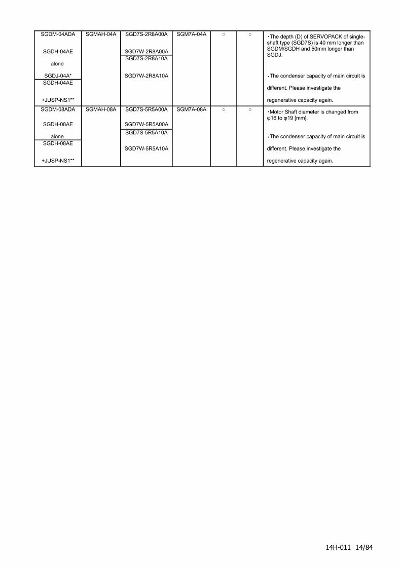
SGDM-04ADA
SGDH-04AE
alone
SGDJ-04A*SGDH-04AE
+JUSP-NS1**
SGMAH-04A SGD7S-2R8A00A
SGD7W-2R8A00ASGD7S-2R8A10A
SGD7W-2R8A10A
SGM7A-04A ○ ○ ・The depth (D) of SERVOPACK of single-shaft type (SGD7S) is 40 mm longer than SGDM/SGDH and 50mm longer than SGDJ.
・The condenser capacity of main circuit is
different. Please investigate the
regenerative capacity again.
SGDM-08ADA
SGDH-08AE
alone SGDH-08AE
+JUSP-NS1**
SGMAH-08A SGD7S-5R5A00A
SGD7W-5R5A00A
SGD7S-5R5A10A
SGD7W-5R5A10A
SGM7A-08A ○ ○ ・Motor Shaft diameter is changed from φ16 to φ19 [mm].
・The condenser capacity of main circuit is
different. Please investigate the
regenerative capacity again.
14H-011 14/84
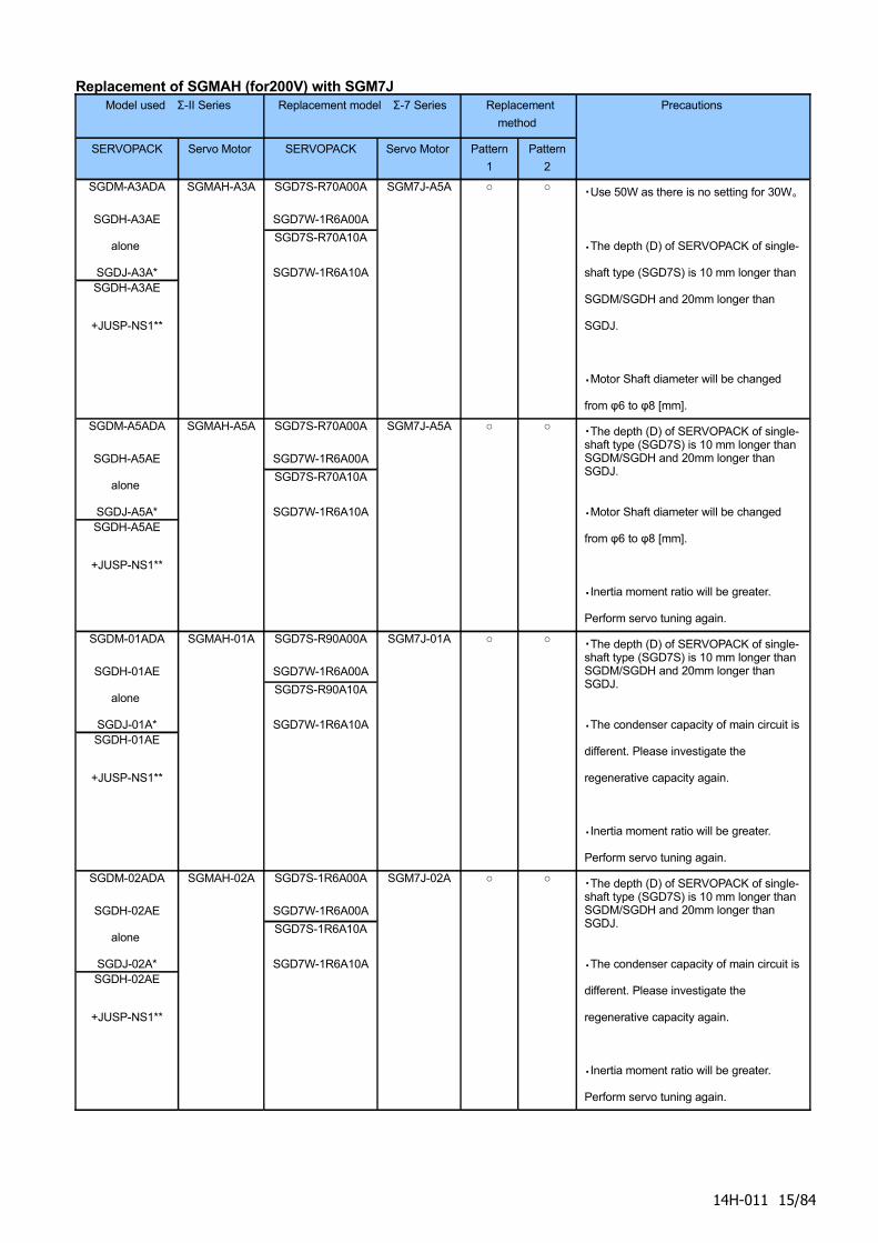
Replacement of SGMAH (for200V) with SGM7JModel used Σ-II Series Replacement model Σ-7 Series Replacement
method
SERVOPACK Servo Motor SERVOPACK Servo Motor Pattern
1
Pattern
2
Precautions
SGDM-A3ADA
SGDH-A3AE
alone
SGDJ-A3A*SGDH-A3AE
+JUSP-NS1**
SGMAH-A3A SGD7S-R70A00A
SGD7W-1R6A00A
SGD7S-R70A10A
SGD7W-1R6A10A
SGM7J-A5A ○ ○ ・Use 50W as there is no setting for 30W。
・The depth (D) of SERVOPACK of single-
shaft type (SGD7S) is 10 mm longer than
SGDM/SGDH and 20mm longer than
SGDJ.
・Motor Shaft diameter will be changed
from φ6 to φ8 [mm].
SGDM-A5ADA
SGDH-A5AE
alone
SGDJ-A5A*SGDH-A5AE
+JUSP-NS1**
SGMAH-A5A SGD7S-R70A00A
SGD7W-1R6A00A
SGD7S-R70A10A
SGD7W-1R6A10A
SGM7J-A5A ○ ○ ・The depth (D) of SERVOPACK of single-shaft type (SGD7S) is 10 mm longer than SGDM/SGDH and 20mm longer than SGDJ.
・Motor Shaft diameter will be changed
from φ6 to φ8 [mm].
・Inertia moment ratio will be greater.
Perform servo tuning again.
SGDM-01ADA
SGDH-01AE
alone
SGDJ-01A*SGDH-01AE
+JUSP-NS1**
SGMAH-01A SGD7S-R90A00A
SGD7W-1R6A00A
SGD7S-R90A10A
SGD7W-1R6A10A
SGM7J-01A ○ ○ ・The depth (D) of SERVOPACK of single-shaft type (SGD7S) is 10 mm longer than SGDM/SGDH and 20mm longer than SGDJ.
・The condenser capacity of main circuit is
different. Please investigate the
regenerative capacity again.
・Inertia moment ratio will be greater.
Perform servo tuning again.
SGDM-02ADA
SGDH-02AE
alone
SGDJ-02A*SGDH-02AE
+JUSP-NS1**
SGMAH-02A SGD7S-1R6A00A
SGD7W-1R6A00A
SGD7S-1R6A10A
SGD7W-1R6A10A
SGM7J-02A ○ ○ ・The depth (D) of SERVOPACK of single-shaft type (SGD7S) is 10 mm longer than SGDM/SGDH and 20mm longer than SGDJ.
・The condenser capacity of main circuit is
different. Please investigate the
regenerative capacity again.
・Inertia moment ratio will be greater.
Perform servo tuning again.
14H-011 15/84
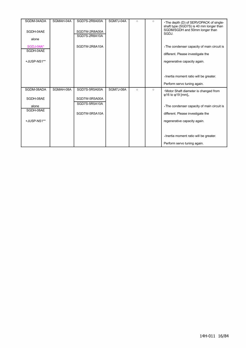
SGDM-04ADA
SGDH-04AE
alone
SGDJ-04A*SGDH-04AE
+JUSP-NS1**
SGMAH-04A SGD7S-2R8A00A
SGD7W-2R8A00ASGD7S-2R8A10A
SGD7W-2R8A10A
SGM7J-04A ○ ○ ・The depth (D) of SERVOPACK of single-shaft type (SGD7S) is 40 mm longer than SGDM/SGDH and 50mm longer than SGDJ.
・The condenser capacity of main circuit is
different. Please investigate the
regenerative capacity again.
・Inertia moment ratio will be greater.
Perform servo tuning again.
SGDM-08ADA
SGDH-08AE
alone SGDH-08AE
+JUSP-NS1**
SGMAH-08A SGD7S-5R5A00A
SGD7W-5R5A00A
SGD7S-5R5A10A
SGD7W-5R5A10A
SGM7J-08A ○ ○ ・Motor Shaft diameter is changed from φ16 to φ19 [mm]。
・The condenser capacity of main circuit is
different. Please investigate the
regenerative capacity again.
・Inertia moment ratio will be greater.
Perform servo tuning again.
14H-011 16/84
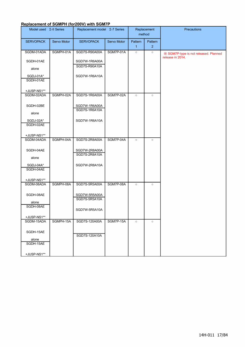
Replacement of SGMPH (for200V) with SGM7PModel used Σ-II Series Replacement model Σ-7 Series Replacement
method
SERVOPACK Servo Motor SERVOPACK Servo Motor Pattern
1
Pattern
2
Precautions
SGDM-01ADA
SGDH-01AE
alone
SGDJ-01A*SGDH-01AE
+JUSP-NS1**
SGMPH-01A SGD7S-R90A00A
SGD7W-1R6A00A
SGD7S-R90A10A
SGD7W-1R6A10A
SGM7P-01A ○ ○
SGDM-02ADA
SGDH-02BE
alone
SGDJ-02A*SGDH-02AE
+JUSP-NS1**
SGMPH-02A SGD7S-1R6A00A
SGD7W-1R6A00ASGD7S-1R6A10A
SGD7W-1R6A10A
SGM7P-02A ○ ○
SGDM-04ADA
SGDH-04AE
alone
SGDJ-04A*SGDH-04AE
+JUSP-NS1**
SGMPH-04A SGD7S-2R8A00A
SGD7W-2R8A00ASGD7S-2R8A10A
SGD7W-2R8A10A
SGM7P-04A ○ ○
SGDM-08ADA
SGDH-08AE
alone SGDH-08AE
+JUSP-NS1**
SGMPH-08A SGD7S-5R5A00A
SGD7W-5R5A00ASGD7S-5R5A10A
SGD7W-5R5A10A
SGM7P-08A ○ ○
SGDM-15ADA
SGDH-15AE
alone SGDH-15AE
+JUSP-NS1**
SGMPH-15A SGD7S-120A00A
SGD7S-120A10A
SGM7P-15A ○ ○
※ SGM7P-type is not released. Planned release in 2014.
14H-011 17/84
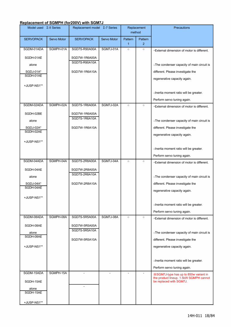
Replacement of SGMPH (for200V) with SGM7JModel used Σ-II Series Replacement model Σ-7 Series Replacement
method
SERVOPACK Servo Motor SERVOPACK Servo Motor Pattern
1
Pattern
2
Precautions
SGDM-01ADA
SGDH-01AE
alone
SGDJ-01A*SGDH-01AE
+JUSP-NS1**
SGMPH-01A SGD7S-R90A00A
SGD7W-1R6A00A
SGD7S-R90A10A
SGD7W-1R6A10A
SGM7J-01A ○ ○ ・External dimension of motor is different.
・The condenser capacity of main circuit is
different. Please investigate the
regenerative capacity again.
・Inertia moment ratio will be greater.
Perform servo tuning again.
SGDM-02ADA
SGDH-02BE
alone
SGDJ-02A*SGDH-02AE
+JUSP-NS1**
SGMPH-02A SGD7S-1R6A00A
SGD7W-1R6A00A
SGD7S-1R6A10A
SGD7W-1R6A10A
SGM7J-02A ○ ○ ・External dimension of motor is different.
・The condenser capacity of main circuit is
different. Please investigate the
regenerative capacity again.
・Inertia moment ratio will be greater.
Perform servo tuning again.
SGDM-04ADA
SGDH-04AE
alone
SGDJ-04A*SGDH-04AE
+JUSP-NS1**
SGMPH-04A SGD7S-2R8A00A
SGD7W-2R8A00A
SGD7S-2R8A10A
SGD7W-2R8A10A
SGM7J-04A ○ ○ ・External dimension of motor is different.
・The condenser capacity of main circuit is
different. Please investigate the
regenerative capacity again.
・Inertia moment ratio will be greater.
Perform servo tuning again.
SGDM-08ADA
SGDH-08AE
alone SGDH-08AE
+JUSP-NS1**
SGMPH-08A SGD7S-5R5A00A
SGD7W-5R5A00A
SGD7S-5R5A10A
SGD7W-5R5A10A
SGM7J-08A ○ ○ ・External dimension of motor is different.
・The condenser capacity of main circuit is
different. Please investigate the
regenerative capacity again.
・Inertia moment ratio will be greater.
Perform servo tuning again.
SGDM-15ADA
SGDH-15AE
alone SGDH-15AE
+JUSP-NS1**
SGMPH-15A -
-
- - - ※SGM7J-type has up to 850w variant in the product lineup. 1.5kW SGMPH cannot be replaced with SGM7J.
14H-011 18/84

14H-011 19/84
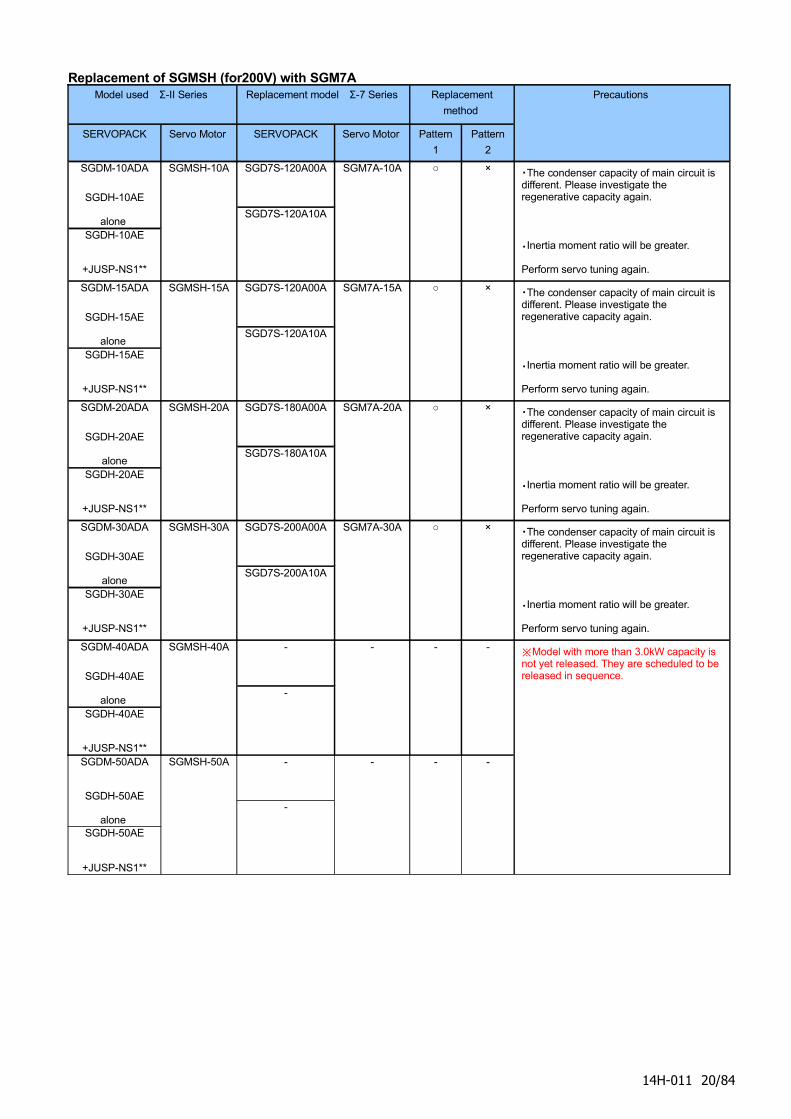
Replacement of SGMSH (for200V) with SGM7AModel used Σ-II Series Replacement model Σ-7 Series Replacement
method
SERVOPACK Servo Motor SERVOPACK Servo Motor Pattern
1
Pattern
2
Precautions
SGDM-10ADA
SGDH-10AE
alone SGDH-10AE
+JUSP-NS1**
SGMSH-10A SGD7S-120A00A
SGD7S-120A10A
SGM7A-10A ○ × ・The condenser capacity of main circuit is different. Please investigate the regenerative capacity again.
・Inertia moment ratio will be greater.
Perform servo tuning again.
SGDM-15ADA
SGDH-15AE
alone SGDH-15AE
+JUSP-NS1**
SGMSH-15A SGD7S-120A00A
SGD7S-120A10A
SGM7A-15A ○ × ・The condenser capacity of main circuit is different. Please investigate the regenerative capacity again.
・Inertia moment ratio will be greater.
Perform servo tuning again.
SGDM-20ADA
SGDH-20AE
aloneSGDH-20AE
+JUSP-NS1**
SGMSH-20A SGD7S-180A00A
SGD7S-180A10A
SGM7A-20A ○ × ・The condenser capacity of main circuit is different. Please investigate the regenerative capacity again.
・Inertia moment ratio will be greater.
Perform servo tuning again.
SGDM-30ADA
SGDH-30AE
aloneSGDH-30AE
+JUSP-NS1**
SGMSH-30A SGD7S-200A00A
SGD7S-200A10A
SGM7A-30A ○ × ・The condenser capacity of main circuit is different. Please investigate the regenerative capacity again.
・Inertia moment ratio will be greater.
Perform servo tuning again.
SGDM-40ADA
SGDH-40AE
alone SGDH-40AE
+JUSP-NS1**
SGMSH-40A -
-
- - -
SGDM-50ADA
SGDH-50AE
alone SGDH-50AE
+JUSP-NS1**
SGMSH-50A -
-
- - -
※Model with more than 3.0kW capacity is not yet released. They are scheduled to be released in sequence.
14H-011 20/84
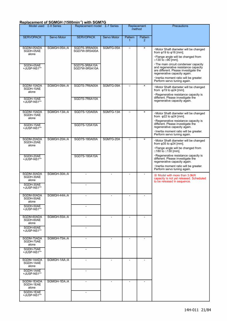
Replacement of SGMGH (1500min-1) with SGM7GModel used Σ-II Series Replacement model Σ-7 Series Replacement
method
SERVOPACK Servo Motor SERVOPACK Servo Motor Pattern 1
Pattern 2
Precautions
SGDM-05ADASGDH-05AE
alone
SGDH-05AE+JUSP-NS1**
SGMGH-05A□A SGD7S-3R8A00ASGD7W-5R5A00A
SGD7S-3R8A10A SGD7W-5R5A10A
SGM7G-05A ○ × ・Motor Shaft diameter will be changed from φ19 to φ16 [mm].
・Flange angle will be changed from □130 to □90 [mm].
・The main circuit condenser capacity and regenerative resistance capacity are different. Please investigate the regenerative capacity again.
・Inertia moment ratio will be greater. Perform servo tuning again.
SGDM-10ADASGDH-10AE
alone
SGDH-10AE+JUSP-NS1**
SGMGH-09A□A SGD7S-7R6A00A
SGD7S-7R6A10A
SGM7G-09A ○ × ・Motor Shaft diameter will be changed from φ19 to φ24 [mm].
・Regenerative resistance capacity is different. Please investigate the regenerative capacity again.
SGDM-15ADASGDH-15AE
alone
SGDH-15AE+JUSP-NS1**
SGMGH-13A□A SGD7S-120A00A
SGD7S-120A10A
SGM7G-13A ○ × ・Motor Shaft diameter will be changed from φ22 to φ24 [mm].
・Regenerative resistance capacity is different. Please investigate the regenerative capacity again.
・Inertia moment ratio will be greater. Perform servo tuning again.
SGDM-20ADASGDH-20AE
alone
SGDH-20AE+JUSP-NS1**
SGMGH-20A□A SGD7S-180A00A
SGD7S-180A10A
SGM7G-20A ○ × ・Motor Shaft diameter will be changed from φ35 to φ24 [mm].
・Flange angle will be changed from □180 to □130 [mm].
・Regenerative resistance capacity is different. Please investigate the regenerative capacity again.
・Inertia moment ratio will be greater. Perform servo tuning again.
SGDM-30ADASGDH-30AE
alone
SGDH-30AE+JUSP-NS1**
SGMGH-30A□A -
-
- - -
SGDM-50ADASGDH-50AE
alone
SGDH-50AE+JUSP-NS1**
SGMGH-44A□A -
-
- - -
SGDM-60ADASGDH-60AE
alone
SGDH-60AE+JUSP-NS1**
SGMGH-55A□A -
-
- - -
SGDM-75ADASGDH-75AE
alone
SGDH-75AE+JUSP-NS1**
SGMGH-75A□A -
-
- - -
SGDM-1AADASGDH-1AAE
alone
SGDH-1AAE+JUSP-NS1**
SGMGH-1AA□A -
-
- - -
SGDM-1EADASGDH-1EAE
alone
SGDH-1EAE+JUSP-NS1**
SGMGH-1EA□A -
-
- - -
※ Model with more than 3.0kW capacity is not yet released. Scheduled to be released in sequence.
14H-011 21/84
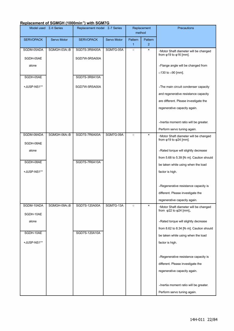
Replacement of SGMGH (1000min-1) with SGM7GModel used Σ-II Series Replacement model Σ-7 Series Replacement
method
SERVOPACK Servo Motor SERVOPACK Servo Motor Pattern
1
Pattern
2
Precautions
SGDM-05ADA
SGDH-05AE
alone
SGDH-05AE
+JUSP-NS1**
SGMGH-03A□B SGD7S-3R8A00A
SGD7W-5R5A00A
SGD7S-3R8A10A
SGD7W-5R5A00A
SGM7G-05A ○ × ・Motor Shaft diameter will be changed from φ19 to φ16 [mm].
・Flange angle will be changed from
□130 to □90 [mm].
・The main circuit condenser capacity
and regenerative resistance capacity
are different. Please investigate the
regenerative capacity again.
・Inertia moment ratio will be greater.
Perform servo tuning again.
SGDM-08ADA
SGDH-08AE
alone
SGDH-08AE
+JUSP-NS1**
SGMGH-06A□B SGD7S-7R6A00A
SGD7S-7R6A10A
SGM7G-09A ○ × ・Motor Shaft diameter will be changed from φ19 to φ24 [mm].
・Rated torque will slightly decrease
from 5.68 to 5.39 [N・m]. Caution should
be taken while using when the load
factor is high.
・Regenerative resistance capacity is
different. Please investigate the
regenerative capacity again.
SGDM-10ADA
SGDH-10AE
alone
SGDH-10AE
+JUSP-NS1**
SGMGH-09A□B SGD7S-120A00A
SGD7S-120A10A
SGM7G-13A ○ × ・Motor Shaft diameter will be changed from φ22 to φ24 [mm]。
・Rated torque will slightly decrease
from 8.62 to 8.34 [N・m]. Caution should
be taken while using when the load
factor is high.
・Regenerative resistance capacity is
different. Please investigate the
regenerative capacity again.
・Inertia moment ratio will be greater.
Perform servo tuning again.
14H-011 22/84
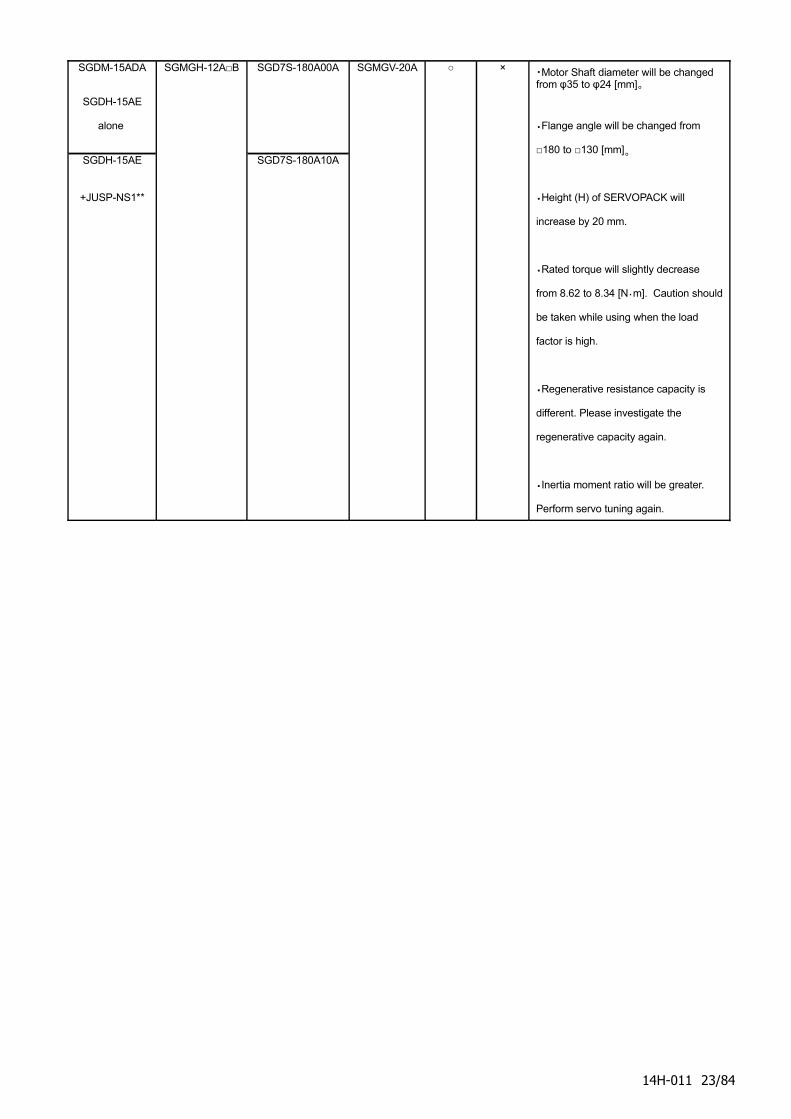
SGDM-15ADA
SGDH-15AE
alone
SGDH-15AE
+JUSP-NS1**
SGMGH-12A□B SGD7S-180A00A
SGD7S-180A10A
SGMGV-20A ○ × ・Motor Shaft diameter will be changed from φ35 to φ24 [mm]。
・Flange angle will be changed from
□180 to □130 [mm]。
・Height (H) of SERVOPACK will
increase by 20 mm.
・Rated torque will slightly decrease
from 8.62 to 8.34 [N・m]. Caution should
be taken while using when the load
factor is high.
・Regenerative resistance capacity is
different. Please investigate the
regenerative capacity again.
・Inertia moment ratio will be greater.
Perform servo tuning again.
14H-011 23/84
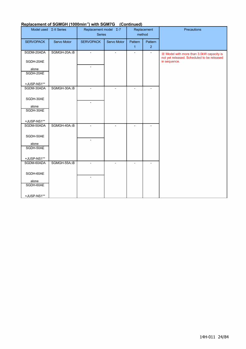
Replacement of SGMGH (1000min-1) with SGM7G (Continued) Model used Σ-II Series Replacement model Σ-7
Series
Replacement
method
SERVOPACK Servo Motor SERVOPACK Servo Motor Pattern
1
Pattern
2
Precautions
SGDM-20ADA
SGDH-20AE
alone SGDH-20AE
+JUSP-NS1**
SGMGH-20A□B -
-
- - -
SGDM-30ADA
SGDH-30AE
alone SGDH-30AE
+JUSP-NS1**
SGMGH-30A□B -
-
- - -
SGDM-50ADA
SGDH-50AE
alone SGDH-50AE
+JUSP-NS1**
SGMGH-40A□B -
-
- - -
SGDM-60ADA
SGDH-60AE
alone SGDH-60AE
+JUSP-NS1**
SGMGH-55A□B -
-
- - -
※ Model with more than 3.0kW capacity is not yet released. Scheduled to be released in sequence.
14H-011 24/84
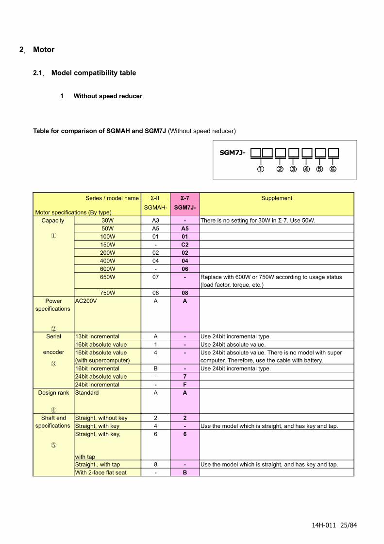
2. Motor
2.1. Model compatibility table
1 Without speed reducer
Table for comparison of SGMAH and SGM7J (Without speed reducer)
SGM7J-
① ② ③ ④ ⑤ ⑥
Series / model name
Motor specifications (By type)
Σ-II Σ-7
SGMAH- SGM7J-
Supplement
Capacity
①
30W A3 - There is no setting for 30W in Σ-7. Use 50W.50W A5 A5
100W 01 01150W - C2200W 02 02400W 04 04600W - 06650W 07 - Replace with 600W or 750W according to usage status
(load factor, torque, etc.)750W 08 08
Power specifications
②
AC200V A A
Serial
encoder
③
13bit incremental A - Use 24bit incremental type. 16bit absolute value 1 - Use 24bit absolute value. 16bit absolute value (with supercomputer)
4 - Use 24bit absolute value. There is no model with super computer. Therefore, use the cable with battery.
16bit incremental B - Use 24bit incremental type. 24bit absolute value - 724bit incremental - F
Design rank
④
Standard A A
Shaft end specifications
⑤
Straight, without key 2 2Straight, with key 4 - Use the model which is straight, and has key and tap.Straight, with key,
with tap
6 6
Straight , with tap 8 - Use the model which is straight, and has key and tap.With 2-face flat seat - B
14H-011 25/84
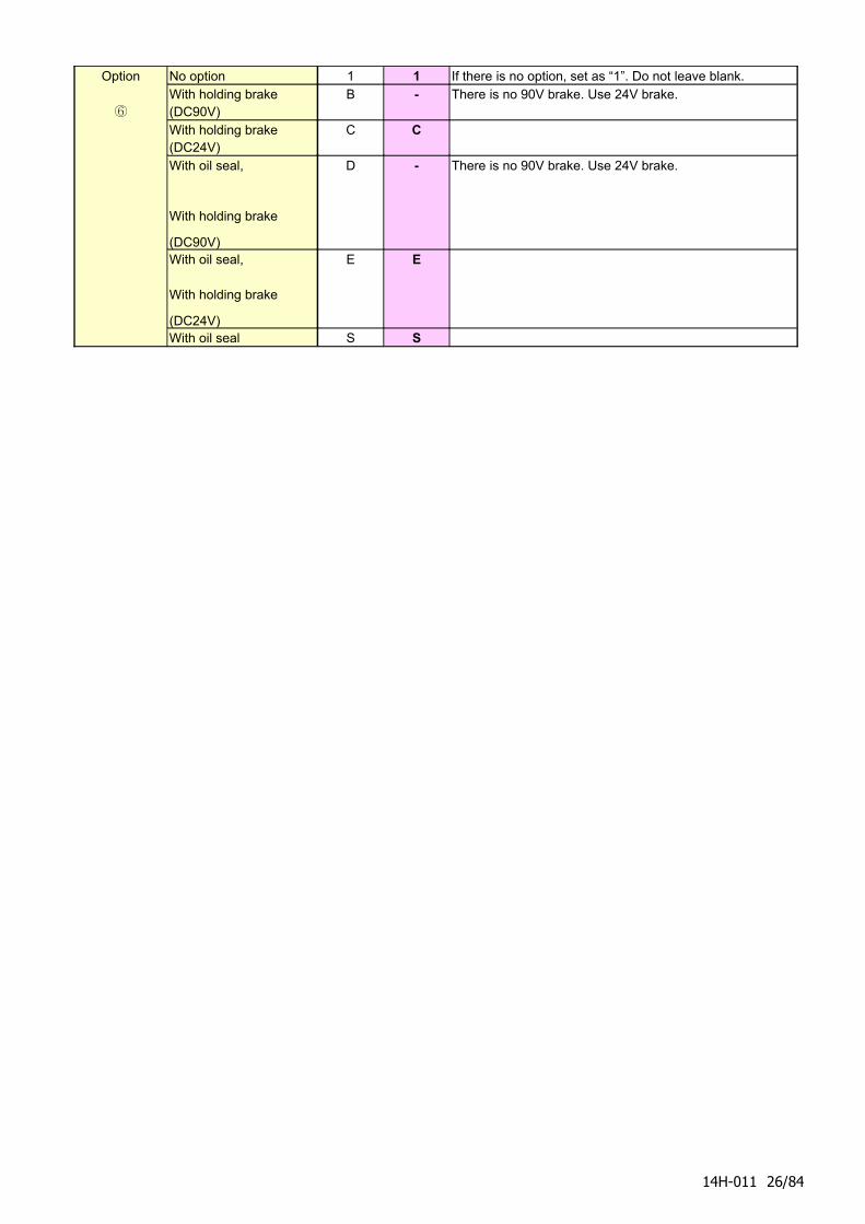
Option
⑥
No option 1 1 If there is no option, set as “1”. Do not leave blank.With holding brake (DC90V)
B - There is no 90V brake. Use 24V brake.
With holding brake (DC24V)
C C
With oil seal,
With holding brake
(DC90V)
D - There is no 90V brake. Use 24V brake.
With oil seal,
With holding brake
(DC24V)
E E
With oil seal S S
14H-011 26/84
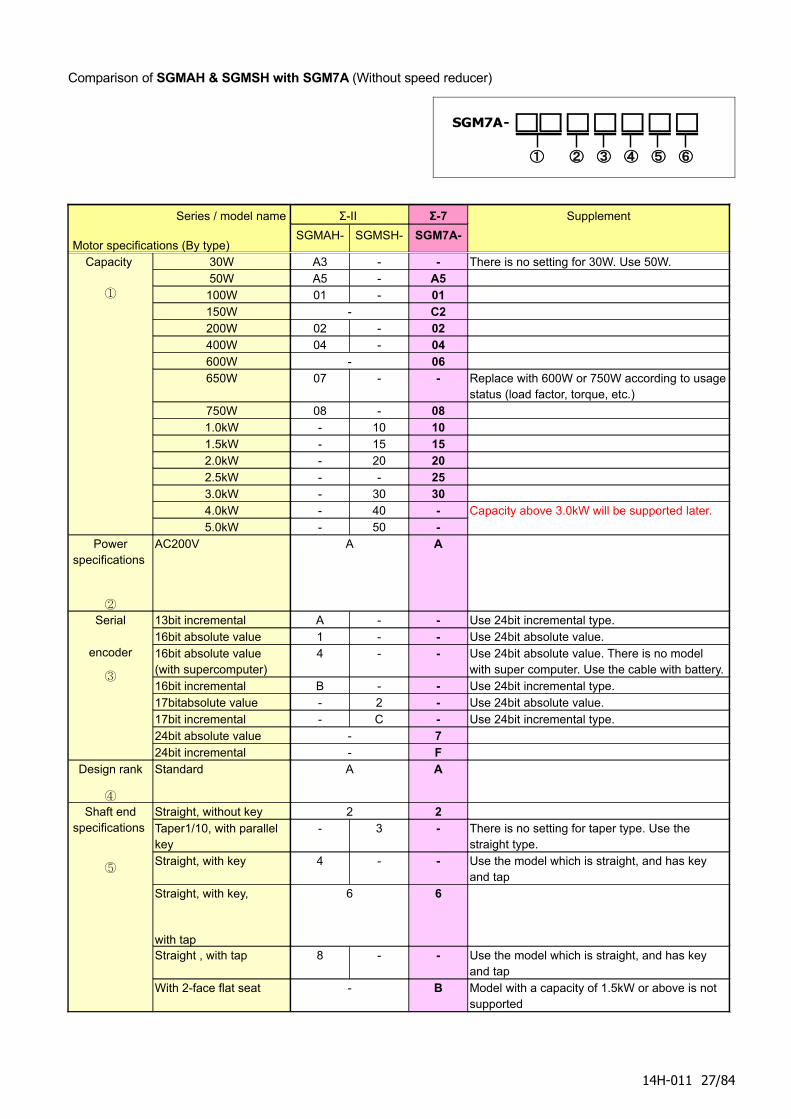
Comparison of SGMAH & SGMSH with SGM7A (Without speed reducer)
SGM7A-
① ② ③ ④ ⑤ ⑥
Series / model name
Motor specifications (By type)
Σ-II Σ-7
SGMAH- SGMSH- SGM7A-
Supplement
Capacity
①
30W A3 - - There is no setting for 30W. Use 50W.50W A5 - A5
100W 01 - 01150W - C2200W 02 - 02400W 04 - 04600W - 06650W 07 - - Replace with 600W or 750W according to usage
status (load factor, torque, etc.)750W 08 - 081.0kW - 10 101.5kW - 15 152.0kW - 20 202.5kW - - 253.0kW - 30 304.0kW - 40 -5.0kW - 50 -
Capacity above 3.0kW will be supported later.
Power specifications
②
AC200V A A
Serial
encoder
③
13bit incremental A - - Use 24bit incremental type. 16bit absolute value 1 - - Use 24bit absolute value. 16bit absolute value (with supercomputer)
4 - - Use 24bit absolute value. There is no model with super computer. Use the cable with battery.
16bit incremental B - - Use 24bit incremental type. 17bitabsolute value - 2 - Use 24bit absolute value. 17bit incremental - C - Use 24bit incremental type. 24bit absolute value - 724bit incremental - F
Design rank
④
Standard A A
Shaft end specifications
⑤
Straight, without key 2 2Taper1/10, with parallel key
- 3 - There is no setting for taper type. Use the straight type.
Straight, with key 4 - - Use the model which is straight, and has key and tap
Straight, with key,
with tap
6 6
Straight , with tap 8 - - Use the model which is straight, and has key and tap
With 2-face flat seat - B Model with a capacity of 1.5kW or above is not supported
14H-011 27/84
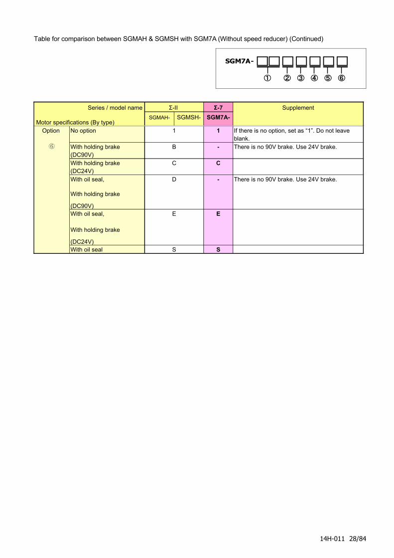
Table for comparison between SGMAH & SGMSH with SGM7A (Without speed reducer) (Continued)
SGM7A-
① ② ③ ④ ⑤ ⑥
Series / model name
Motor specifications (By type)
Σ-II Σ-7
SGMAH- SGMSH- SGM7A-
Supplement
Option
⑥
No option 1 1 If there is no option, set as “1”. Do not leave blank.
With holding brake (DC90V)
B - There is no 90V brake. Use 24V brake.
With holding brake (DC24V)
C C
With oil seal,
With holding brake
(DC90V)
D - There is no 90V brake. Use 24V brake.
With oil seal,
With holding brake
(DC24V)
E E
With oil seal S S
14H-011 28/84
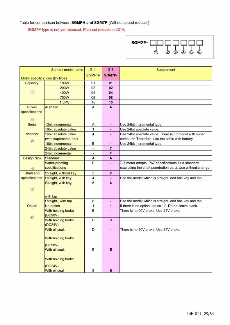
Table for comparison between SGMPH and SGM7P (Without speed reducer)
SGM7P-type is not yet released. Planned release in 2014.
SGM7P-
① ② ③ ④ ⑤ ⑥
Series / model name
Motor specifications (By type)
Σ-II Σ-7
SGMPH- SGM7P-
Supplement
Capacity
①
100W 01 01200W 02 02400W 04 04750W 08 081.5kW 15 15
Power specifications
②
AC200V A A
Serial
encoder
③
13bit incremental A - Use 24bit incremental type. 16bit absolute value 1 - Use 24bit absolute value. 16bit absolute value (with supercomputer)
4 - Use 24bit absolute value. There is no model with super computer. Therefore, use the cable with battery.
16bit incremental B - Use 24bit incremental type. 24bit absolute value - 724bit incremental - F
Design rank
④
Standard A AWater-proofing specifications
E - Σ-7 motor adopts IP67 specifications as a standard (excluding the shaft penetration part). Use without change.
Shaft end specifications
⑤
Straight, without key 2 2Straight, with key 4 - Use the model which is straight, and has key and tap.Straight, with key,
with tap
6 6
Straight , with tap 8 - Use the model which is straight, and has key and tap.Option
⑥
No option 1 1 If there is no option, set as “1”. Do not leave blank.With holding brake (DC90V)
B - There is no 90V brake. Use 24V brake.
With holding brake (DC24V)
C C
With oil seal,
With holding brake
(DC90V)
D - There is no 90V brake. Use 24V brake.
With oil seal,
With holding brake
(DC24V)
E E
With oil seal S S
14H-011 29/84
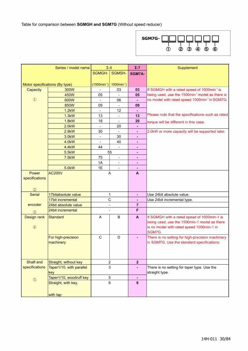
Table for comparison between SGMGH and SGM7G (Without speed reducer)
SGM7G-
① ② ③ ④ ⑤ ⑥
Series / model name
Motor specifications (By type)
Σ-II Σ-7
SGMGH-
(1500min-1)
SGMSH-
1000min-1)
SGM7A-
Supplement
Capacity
①
300W - 03 03450W 05 - 05600W - 06 -850W 09 - 091.2kW - 12 -1.3kW 13 - 131.8kW 18 - 202.0kW - 20 -
If SGMGH with a rated speed of 1000min-1 is being used, use the 1500min-1 model as there is no model with rated speed 1000min-1 in SGM7G.
Please note that the specifications such as rated
torque will be different in this case.
2.9kW 30 - -3.0kW - 30 -4.0kW - 40 -4.4kW 44 - -5.5kW 55 -7.5kW 75 - -
1A - -5.0kW 1E - -
2.0kW or more capacity will be supported later.
Power specifications
②
AC200V A A
Serial
encoder
③
17bitabsolute value 1 - Use 24bit absolute value. 17bit incremental C - Use 24bit incremental type. 24bit absolute value - 724bit incremental - F
Design rank
④
Standard A B A If SGMGH with a rated speed of 1000min-1 is being used, use the 1500min-1 model as there is no model with rated speed 1000min-1 in SGM7G.
For high-precision machinery
C D - There is no setting for high-precision machinery in SGM7G. Use the standard specifications.
Shaft end specifications
⑤
Straight, without key 2 2Taper1/10, with parallel key
3 -
Taper1/10, woodruff key 5 -
There is no setting for taper type. Use the straight type.
Straight, with key,
with tap
6 6
14H-011 30/84
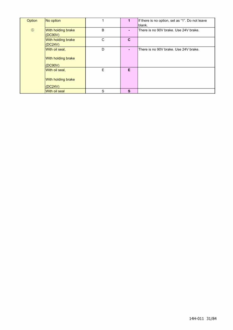
Option
⑥
No option 1 1 If there is no option, set as “1”. Do not leave blank.
With holding brake (DC90V)
B - There is no 90V brake. Use 24V brake.
With holding brake (DC24V)
C C
With oil seal,
With holding brake
(DC90V)
D - There is no 90V brake. Use 24V brake.
With oil seal,
With holding brake
(DC24V)
E E
With oil seal S S
14H-011 31/84
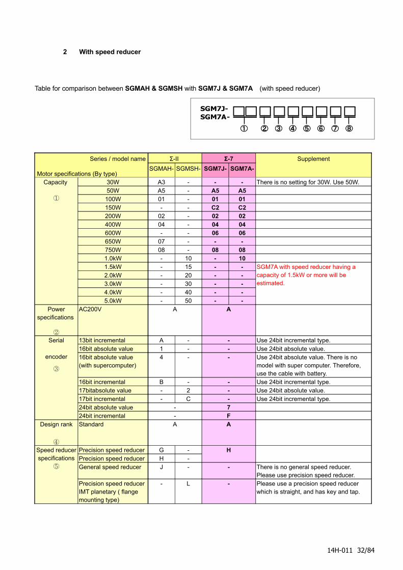
2 With speed reducer
Table for comparison between SGMAH & SGMSH with SGM7J & SGM7A (with speed reducer)
SGM7J-SGM7A-
① ② ③ ④ ⑤ ⑥ ⑦ ⑧
Series / model name
Motor specifications (By type)
Σ-II Σ-7
SGMAH- SGMSH- SGM7J- SGM7A-
Supplement
Capacity
①
30W A3 - - - There is no setting for 30W. Use 50W.50W A5 - A5 A5
100W 01 - 01 01150W - - C2 C2200W 02 - 02 02400W 04 - 04 04600W - - 06 06650W 07 - - -750W 08 - 08 081.0kW - 10 - 101.5kW - 15 - -2.0kW - 20 - -3.0kW - 30 - -4.0kW - 40 - -5.0kW - 50 - -
SGM7A with speed reducer having a capacity of 1.5kW or more will be estimated.
Power specifications
②
AC200V A A
Serial
encoder
③
13bit incremental A - - Use 24bit incremental type. 16bit absolute value 1 - - Use 24bit absolute value. 16bit absolute value (with supercomputer)
4 - - Use 24bit absolute value. There is no model with super computer. Therefore, use the cable with battery.
16bit incremental B - - Use 24bit incremental type. 17bitabsolute value - 2 - Use 24bit absolute value. 17bit incremental - C - Use 24bit incremental type. 24bit absolute value - 724bit incremental - F
Design rank
④
Standard A A
Speed reducer specifications
⑤
Precision speed reducer G -Precision speed reducer H -
H
General speed reducer J - - There is no general speed reducer. Please use precision speed reducer.
Precision speed reducer IMT planetary ( flange mounting type)
- L - Please use a precision speed reducer which is straight, and has key and tap.
14H-011 32/84
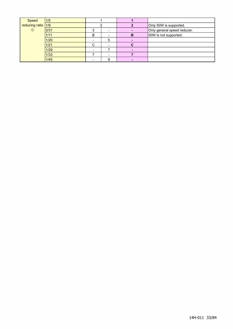
Speed reducing ratio
⑥
1/5 1 11/9 2 2 Only 50W is supported.3/31 3 - - Only general speed reducer.1/11 B - B 50W is not supported.1/20 - 5 -1/21 C - C1/29 - 7 -1/33 7 - 71/45 - 8 -
14H-011 33/84
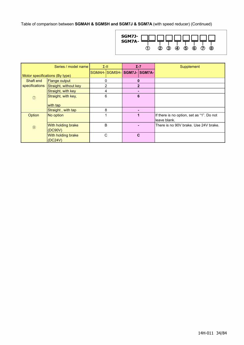
Table of comparison between SGMAH & SGMSH and SGM7J & SGM7A (with speed reducer) (Continued)
SGM7J-SGM7A-
① ② ③ ④ ⑤ ⑥ ⑦ ⑧
Series / model name
Motor specifications (By type)
Σ-II Σ-7
SGMAH- SGMSH- SGM7J- SGM7A-
Supplement
Shaft end specifications
⑦
Flange output 0 0Straight, without key 2 2Straight, with key 4 -Straight, with key,
with tap
6 6
Straight , with tap 8 -Option
⑧
No option 1 1 If there is no option, set as “1”. Do not leave blank.
With holding brake (DC90V)
B - There is no 90V brake. Use 24V brake.
With holding brake (DC24V)
C C
14H-011 34/84
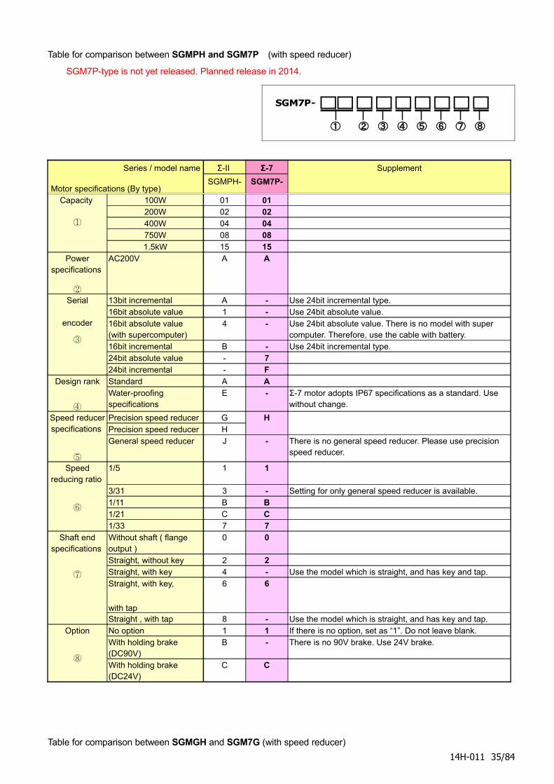
Table for comparison between SGMPH and SGM7P (with speed reducer)
SGM7P-type is not yet released. Planned release in 2014.
SGM7P-
① ② ③ ④ ⑤ ⑥ ⑦ ⑧
Series / model name
Motor specifications (By type)
Σ-II Σ-7
SGMPH- SGM7P-
Supplement
Capacity
①
100W 01 01200W 02 02400W 04 04750W 08 081.5kW 15 15
Power specifications
②
AC200V A A
Serial
encoder
③
13bit incremental A - Use 24bit incremental type. 16bit absolute value 1 - Use 24bit absolute value. 16bit absolute value (with supercomputer)
4 - Use 24bit absolute value. There is no model with super computer. Therefore, use the cable with battery.
16bit incremental B - Use 24bit incremental type. 24bit absolute value - 724bit incremental - F
Design rank
④
Standard A AWater-proofing specifications
E - Σ-7 motor adopts IP67 specifications as a standard. Use without change.
Speed reducer specifications
⑤
Precision speed reducer GPrecision speed reducer H
H
General speed reducer J - There is no general speed reducer. Please use precision speed reducer.
Speed reducing ratio
⑥
1/5 1 1
3/31 3 - Setting for only general speed reducer is available.1/11 B B1/21 C C1/33 7 7
Shaft end specifications
⑦
Without shaft ( flange output )
0 0
Straight, without key 2 2Straight, with key 4 - Use the model which is straight, and has key and tap.Straight, with key,
with tap
6 6
Straight , with tap 8 - Use the model which is straight, and has key and tap.Option
⑧
No option 1 1 If there is no option, set as “1”. Do not leave blank.With holding brake (DC90V)
B - There is no 90V brake. Use 24V brake.
With holding brake (DC24V)
C C
Table for comparison between SGMGH and SGM7G (with speed reducer)
14H-011 35/84

Values for SGM7G model with speed reducer will be estimated.
14H-011 36/84
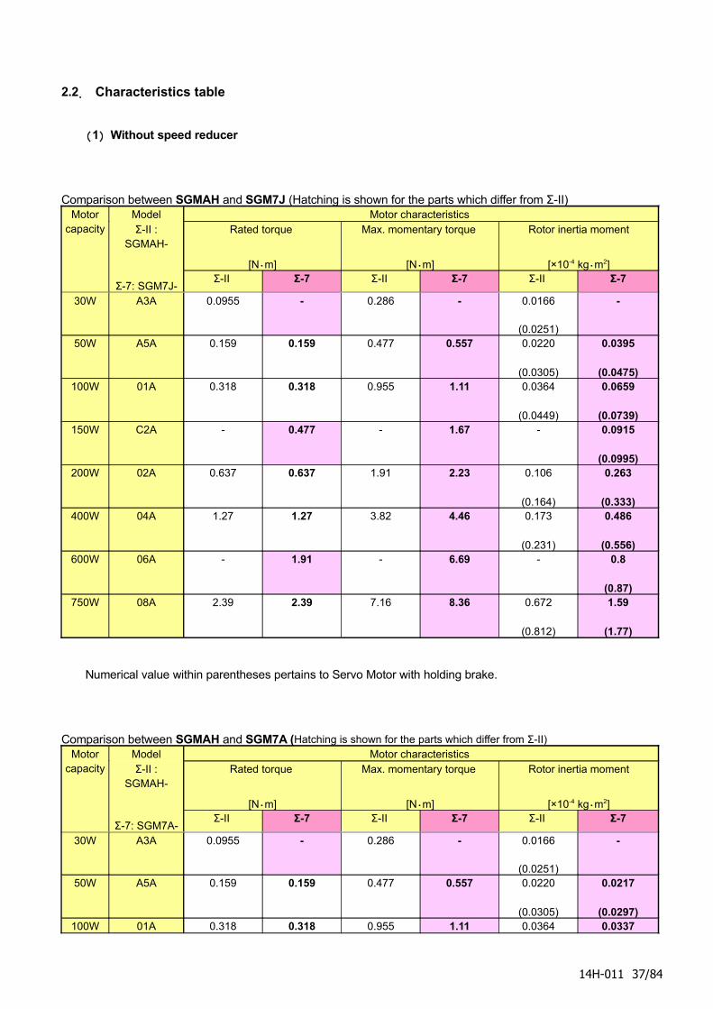
2.2. Characteristics table
(1) Without speed reducer
Comparison between SGMAH and SGM7J (Hatching is shown for the parts which differ from Σ-II) Motor
capacity Model Motor characteristics Σ-II :
SGMAH-
Σ-7: SGM7J-
Rated torque
[N・m]
Max. momentary torque
[N・m]
Rotor inertia moment
[×10-4 kg・m2]Σ-II Σ-7 Σ-II Σ-7 Σ-II Σ-7
30W A3A 0.0955 - 0.286 - 0.0166
(0.0251)
-
50W A5A 0.159 0.159 0.477 0.557 0.0220
(0.0305)
0.0395
(0.0475) 100W 01A 0.318 0.318 0.955 1.11 0.0364
(0.0449)
0.0659
(0.0739) 150W C2A - 0.477 - 1.67 - 0.0915
(0.0995) 200W 02A 0.637 0.637 1.91 2.23 0.106
(0.164)
0.263
(0.333) 400W 04A 1.27 1.27 3.82 4.46 0.173
(0.231)
0.486
(0.556) 600W 06A - 1.91 - 6.69 - 0.8
(0.87) 750W 08A 2.39 2.39 7.16 8.36 0.672
(0.812)
1.59
(1.77)
Numerical value within parentheses pertains to Servo Motor with holding brake.
Comparison between SGMAH and SGM7A (Hatching is shown for the parts which differ from Σ-II)Motor
capacity Model Motor characteristics Σ-II :
SGMAH-
Σ-7: SGM7A-
Rated torque
[N・m]
Max. momentary torque
[N・m]
Rotor inertia moment
[×10-4 kg・m2]Σ-II Σ-7 Σ-II Σ-7 Σ-II Σ-7
30W A3A 0.0955 - 0.286 - 0.0166
(0.0251)
-
50W A5A 0.159 0.159 0.477 0.557 0.0220
(0.0305)
0.0217
(0.0297) 100W 01A 0.318 0.318 0.955 1.11 0.0364 0.0337
14H-011 37/84
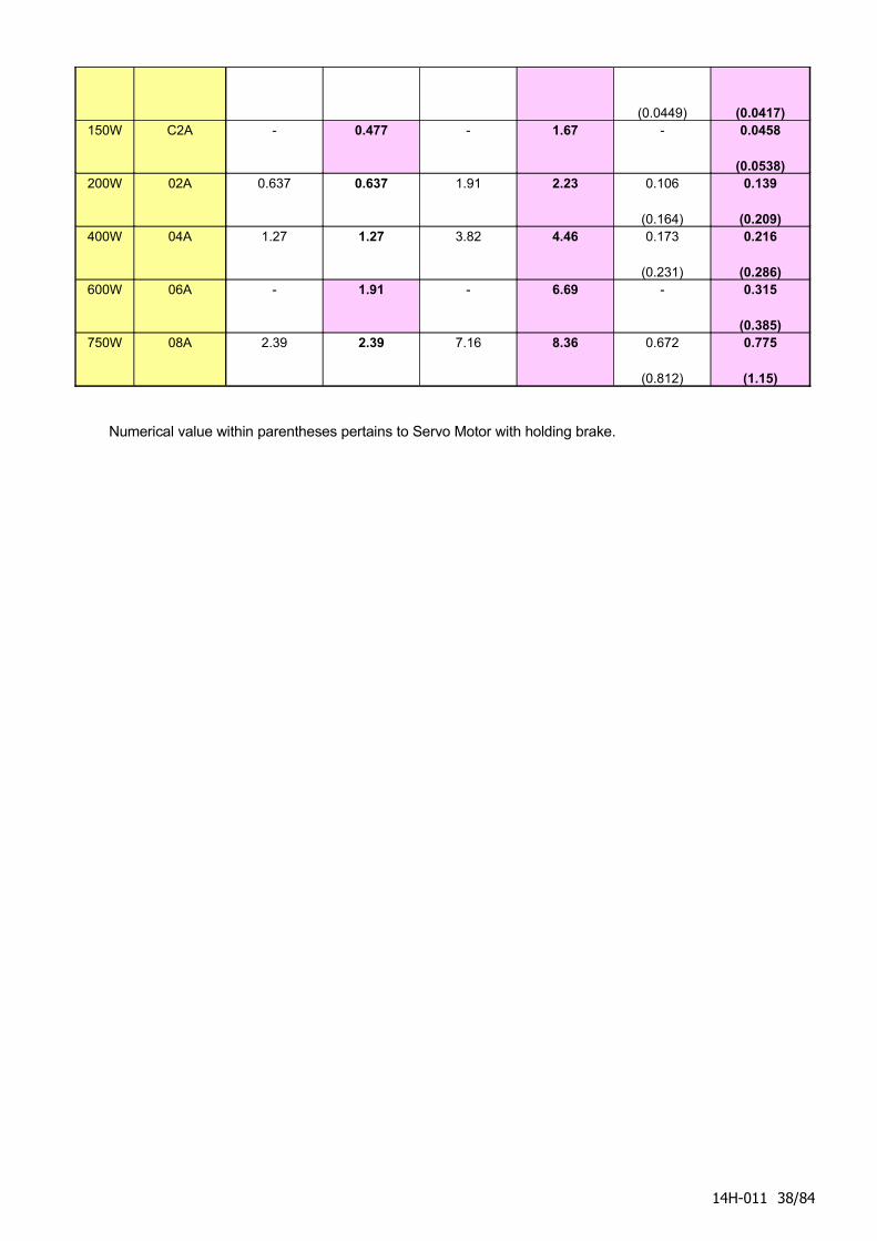
(0.0449) (0.0417) 150W C2A - 0.477 - 1.67 - 0.0458
(0.0538) 200W 02A 0.637 0.637 1.91 2.23 0.106
(0.164)
0.139
(0.209) 400W 04A 1.27 1.27 3.82 4.46 0.173
(0.231)
0.216
(0.286) 600W 06A - 1.91 - 6.69 - 0.315
(0.385) 750W 08A 2.39 2.39 7.16 8.36 0.672
(0.812)
0.775
(1.15)
Numerical value within parentheses pertains to Servo Motor with holding brake.
14H-011 38/84
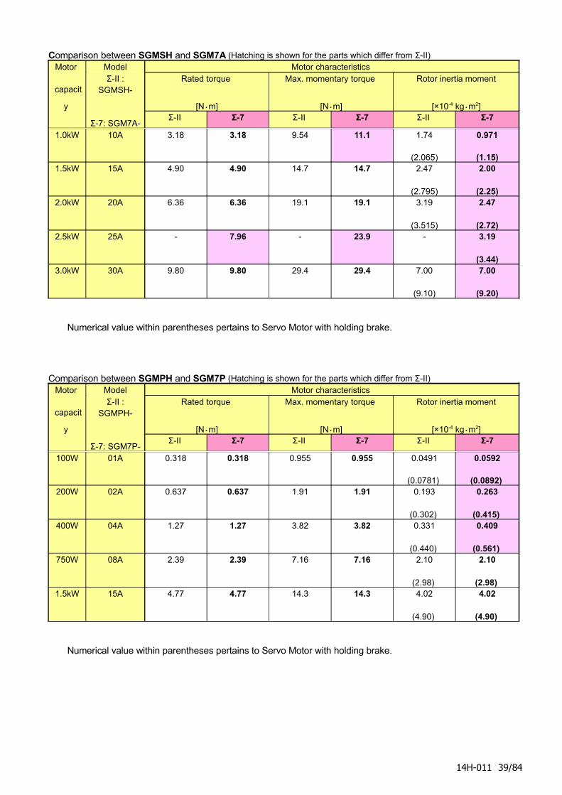
Comparison between SGMSH and SGM7A (Hatching is shown for the parts which differ from Σ-II) Motor
capacit
y
Model Motor characteristics Σ-II :
SGMSH-
Σ-7: SGM7A-
Rated torque
[N・m]
Max. momentary torque
[N・m]
Rotor inertia moment
[×10-4 kg・m2]Σ-II Σ-7 Σ-II Σ-7 Σ-II Σ-7
1.0kW 10A 3.18 3.18 9.54 11.1 1.74
(2.065)
0.971
(1.15) 1.5kW 15A 4.90 4.90 14.7 14.7 2.47
(2.795)
2.00
(2.25) 2.0kW 20A 6.36 6.36 19.1 19.1 3.19
(3.515)
2.47
(2.72) 2.5kW 25A - 7.96 - 23.9 - 3.19
(3.44) 3.0kW 30A 9.80 9.80 29.4 29.4 7.00
(9.10)
7.00
(9.20)
Numerical value within parentheses pertains to Servo Motor with holding brake.
Comparison between SGMPH and SGM7P (Hatching is shown for the parts which differ from Σ-II) Motor
capacit
y
Model Motor characteristics Σ-II :
SGMPH-
Σ-7: SGM7P-
Rated torque
[N・m]
Max. momentary torque
[N・m]
Rotor inertia moment
[×10-4 kg・m2]Σ-II Σ-7 Σ-II Σ-7 Σ-II Σ-7
100W 01A 0.318 0.318 0.955 0.955 0.0491
(0.0781)
0.0592
(0.0892) 200W 02A 0.637 0.637 1.91 1.91 0.193
(0.302)
0.263
(0.415) 400W 04A 1.27 1.27 3.82 3.82 0.331
(0.440)
0.409
(0.561) 750W 08A 2.39 2.39 7.16 7.16 2.10
(2.98)
2.10
(2.98) 1.5kW 15A 4.77 4.77 14.3 14.3 4.02
(4.90)
4.02
(4.90)
Numerical value within parentheses pertains to Servo Motor with holding brake.
14H-011 39/84
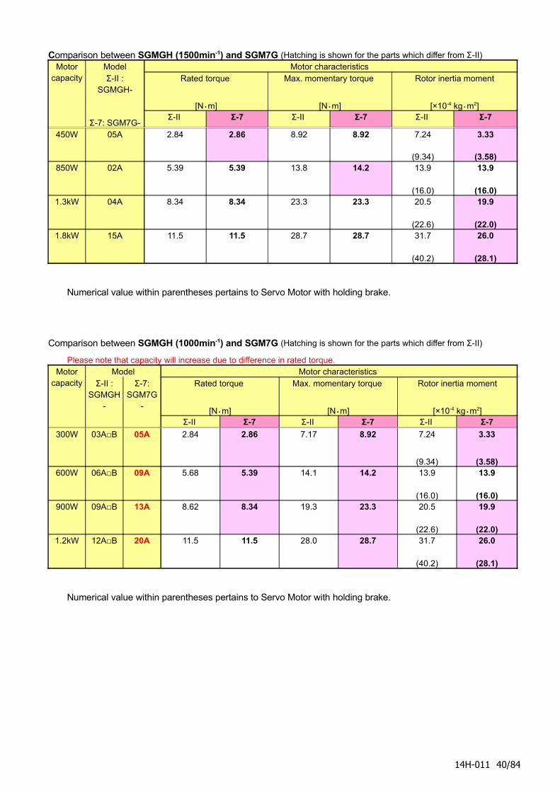
Comparison between SGMGH (1500min-1) and SGM7G (Hatching is shown for the parts which differ from Σ-II) Motor
capacity Model Motor characteristics Σ-II :
SGMGH-
Σ-7: SGM7G-
Rated torque
[N・m]
Max. momentary torque
[N・m]
Rotor inertia moment
[×10-4 kg・m2]Σ-II Σ-7 Σ-II Σ-7 Σ-II Σ-7
450W 05A 2.84 2.86 8.92 8.92 7.24
(9.34)
3.33
(3.58) 850W 02A 5.39 5.39 13.8 14.2 13.9
(16.0)
13.9
(16.0) 1.3kW 04A 8.34 8.34 23.3 23.3 20.5
(22.6)
19.9
(22.0) 1.8kW 15A 11.5 11.5 28.7 28.7 31.7
(40.2)
26.0
(28.1)
Numerical value within parentheses pertains to Servo Motor with holding brake.
Comparison between SGMGH (1000min-1) and SGM7G (Hatching is shown for the parts which differ from Σ-II)
Please note that capacity will increase due to difference in rated torque. Motor
capacity Model Motor characteristics
Σ-II : SGMGH
-
Σ-7: SGM7G
-
Rated torque
[N・m]
Max. momentary torque
[N・m]
Rotor inertia moment
[×10-4 kg・m2]Σ-II Σ-7 Σ-II Σ-7 Σ-II Σ-7
300W 03A□B 05A 2.84 2.86 7.17 8.92 7.24
(9.34)
3.33
(3.58) 600W 06A□B 09A 5.68 5.39 14.1 14.2 13.9
(16.0)
13.9
(16.0) 900W 09A□B 13A 8.62 8.34 19.3 23.3 20.5
(22.6)
19.9
(22.0) 1.2kW 12A□B 20A 11.5 11.5 28.0 28.7 31.7
(40.2)
26.0
(28.1)
Numerical value within parentheses pertains to Servo Motor with holding brake.
14H-011 40/84
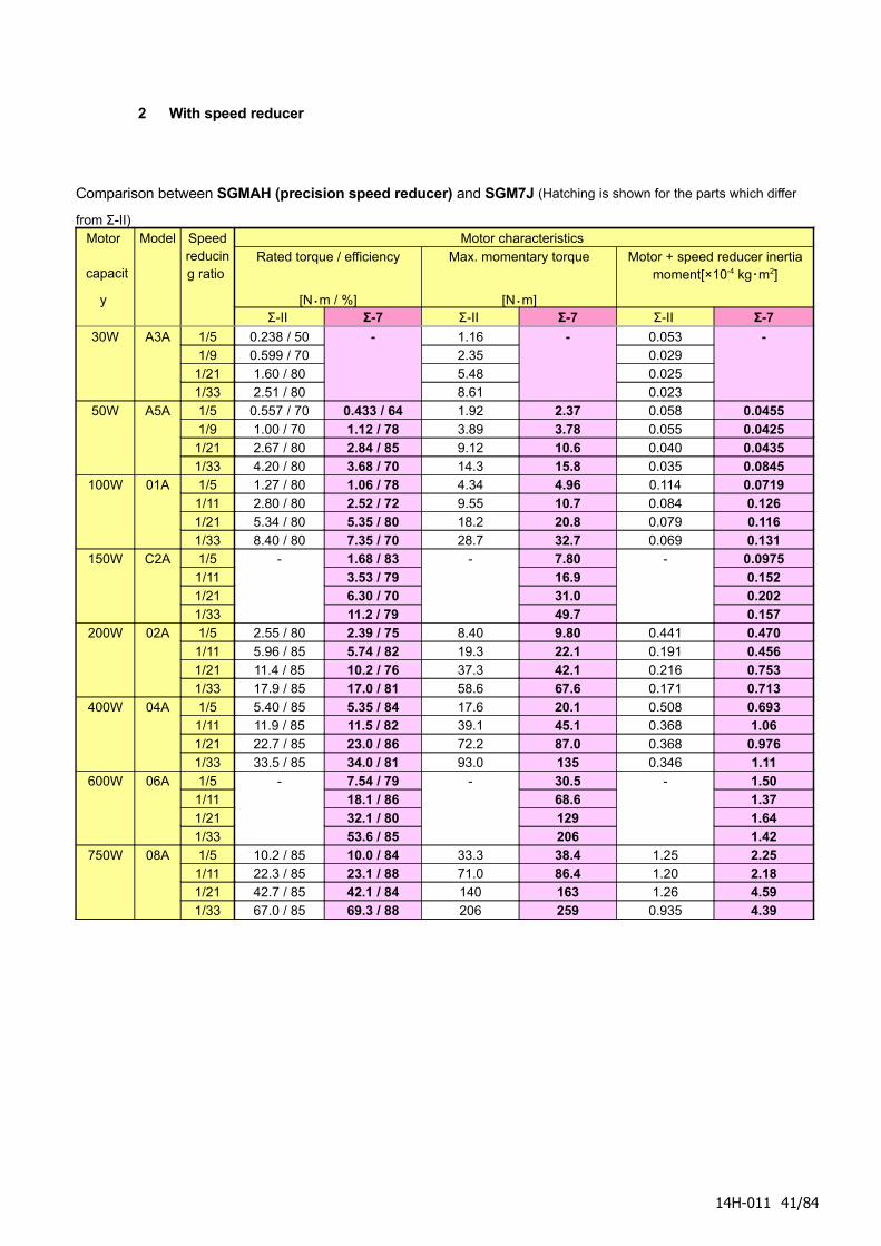
2 With speed reducer
Comparison between SGMAH (precision speed reducer) and SGM7J (Hatching is shown for the parts which differ
from Σ-II) Motor
capacit
y
Model Speed reducing ratio
Motor characteristics Rated torque / efficiency
[N・m / %]
Max. momentary torque
[N・m]
Motor + speed reducer inertia moment[×10-4 kg・m2]
Σ-II Σ-7 Σ-II Σ-7 Σ-II Σ-7
30W A3A 1/5 0.238 / 501/9 0.599 / 70
1/21 1.60 / 801/33 2.51 / 80
- 1.162.355.488.61
- 0.0530.0290.0250.023
-
50W A5A 1/5 0.557 / 70 0.433 / 64 1.92 2.37 0.058 0.04551/9 1.00 / 70 1.12 / 78 3.89 3.78 0.055 0.0425
1/21 2.67 / 80 2.84 / 85 9.12 10.6 0.040 0.04351/33 4.20 / 80 3.68 / 70 14.3 15.8 0.035 0.0845
100W 01A 1/5 1.27 / 80 1.06 / 78 4.34 4.96 0.114 0.07191/11 2.80 / 80 2.52 / 72 9.55 10.7 0.084 0.1261/21 5.34 / 80 5.35 / 80 18.2 20.8 0.079 0.1161/33 8.40 / 80 7.35 / 70 28.7 32.7 0.069 0.131
150W C2A 1/51/111/211/33
- 1.68 / 833.53 / 796.30 / 7011.2 / 79
- 7.8016.931.049.7
- 0.09750.1520.2020.157
200W 02A 1/5 2.55 / 80 2.39 / 75 8.40 9.80 0.441 0.4701/11 5.96 / 85 5.74 / 82 19.3 22.1 0.191 0.4561/21 11.4 / 85 10.2 / 76 37.3 42.1 0.216 0.7531/33 17.9 / 85 17.0 / 81 58.6 67.6 0.171 0.713
400W 04A 1/5 5.40 / 85 5.35 / 84 17.6 20.1 0.508 0.6931/11 11.9 / 85 11.5 / 82 39.1 45.1 0.368 1.061/21 22.7 / 85 23.0 / 86 72.2 87.0 0.368 0.9761/33 33.5 / 85 34.0 / 81 93.0 135 0.346 1.11
600W 06A 1/51/111/211/33
- 7.54 / 7918.1 / 8632.1 / 8053.6 / 85
- 30.568.6129206
- 1.501.371.641.42
750W 08A 1/5 10.2 / 85 10.0 / 84 33.3 38.4 1.25 2.251/11 22.3 / 85 23.1 / 88 71.0 86.4 1.20 2.181/21 42.7 / 85 42.1 / 84 140 163 1.26 4.591/33 67.0 / 85 69.3 / 88 206 259 0.935 4.39
14H-011 41/84

Comparison between SGMAH (general speed reducer) and SGM7J (Hatching is shown for the parts which differ from
Σ-II) Motor
capacity Model Speed
reducing ratio
Motor characteristics Rated torque / efficiency
[N・m / %]
Max. momentary torque
[N・m]
Motor + speed reducer inertia moment
[×10-4 kg・m2]Σ-II Σ-7 Σ-II Σ-7 Σ-II Σ-7
30W A3A 1/5 0.238 / 503/31 0.687 / 701/21 1.60 / 801/33 2.51 / 80
- 1.162.375.488.61
- 0.0440.0330.0230.021
-
50W A5A 1/5 0.557 / 70 0.433 / 64 1.92 2.37 0.050 0.04551/9 - 1.12 / 78 - 3.78 - 0.0425
3/31 1.15 / 70 - 3.95 - 0.040 -1/21 2.67 / 80 2.84 / 85 9.07 10.6 0.036 0.04351/33 4.20 / 80 3.68 / 70 14.3 15.8 0.032 0.0845
100W 01A 1/5 1.27 / 80 1.06 / 78 4.32 4.96 0.099 0.07193/31 2.63 / 80 - 8.88 - 0.054 -1/11 - 2.52 / 72 - 10.7 - 0.1261/21 5.34 / 80 5.35 / 80 18.1 20.8 0.071 0.1161/33 8.40 / 80 7.35 / 70 28.4 32.7 0.057 0.131
150W C2A 1/51/111/211/33
- 1.68 / 833.53 / 796.30 / 7011.2 / 79
7.8016.931.049.7
0.09750.1520.2020.157
200W 02A 1/5 2.55 / 80 2.39 / 75 8.60 9.80 0.299 0.4703/31 5.27 / 80 - 17.8 - 0.196 -1/11 - 5.74 / 82 - 22.1 - 0.4561/21 10.7 / 80 10.2 / 76 36.1 42.1 0.211 0.7531/33 16.8 / 80 17.0 / 81 56.7 67.6 0.181 0.713
400W 04A 1/5 5.08 / 80 5.35 / 84 17.2 20.1 0.366 0.6933/31 10.5 / 80 - 35.5 - 0.353 -1/11 - 11.5 / 82 - 45.1 - 1.061/21 21.3 / 80 23.0 / 86 72.2 87.0 0.403 0.9761/33 33.5 / 80 34.0 / 81 113 135 0.338 1.11
600W 06A 1/51/111/211/33
- 7.54 / 7918.1 / 8632.1 / 8053.6 / 85
- 30.568.6129206
- 1.501.371.641.42
750W 08A 1/5 9.56 / 80 10.0 / 84 32.0 38.4 1.12 2.253/31 19.8 / 80 - 66.6 - 1.10 -1/11 - 23.1 / 88 - 86.4 - 2.181/21 40.2 / 80 42.1 / 84 134 163 1.15 4.591/33 63.1 / 80 69.3 / 88 212 259 0.972 4.39
14H-011 42/84
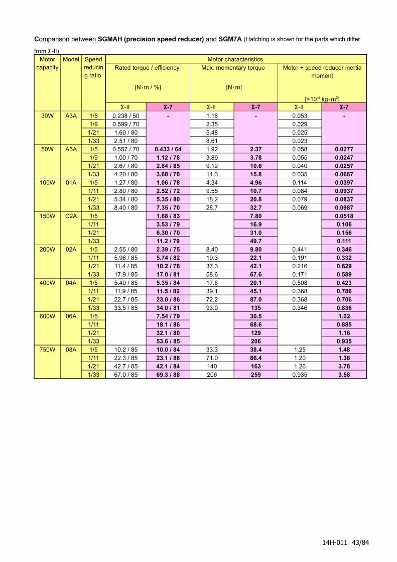
Comparison between SGMAH (precision speed reducer) and SGM7A (Hatching is shown for the parts which differ
from Σ-II) Motor
capacity Model Speed
reducing ratio
Motor characteristics Rated torque / efficiency
[N・m / %]
Max. momentary torque
[N・m]
Motor + speed reducer inertia moment
[×10-4 kg・m2]Σ-II Σ-7 Σ-II Σ-7 Σ-II Σ-7
30W A3A 1/5 0.238 / 501/9 0.599 / 70
1/21 1.60 / 801/33 2.51 / 80
- 1.162.355.488.61
- 0.0530.0290.0250.023
-
50W A5A 1/5 0.557 / 70 0.433 / 64 1.92 2.37 0.058 0.02771/9 1.00 / 70 1.12 / 78 3.89 3.78 0.055 0.0247
1/21 2.67 / 80 2.84 / 85 9.12 10.6 0.040 0.02571/33 4.20 / 80 3.68 / 70 14.3 15.8 0.035 0.0667
100W 01A 1/5 1.27 / 80 1.06 / 78 4.34 4.96 0.114 0.03971/11 2.80 / 80 2.52 / 72 9.55 10.7 0.084 0.09371/21 5.34 / 80 5.35 / 80 18.2 20.8 0.079 0.08371/33 8.40 / 80 7.35 / 70 28.7 32.7 0.069 0.0987
150W C2A 1/51/111/211/33
1.68 / 833.53 / 796.30 / 7011.2 / 79
7.8016.931.049.7
0.05180.1060.1560.111
200W 02A 1/5 2.55 / 80 2.39 / 75 8.40 9.80 0.441 0.3461/11 5.96 / 85 5.74 / 82 19.3 22.1 0.191 0.3321/21 11.4 / 85 10.2 / 76 37.3 42.1 0.216 0.6291/33 17.9 / 85 17.0 / 81 58.6 67.6 0.171 0.589
400W 04A 1/5 5.40 / 85 5.35 / 84 17.6 20.1 0.508 0.4231/11 11.9 / 85 11.5 / 82 39.1 45.1 0.368 0.7861/21 22.7 / 85 23.0 / 86 72.2 87.0 0.368 0.7061/33 33.5 / 85 34.0 / 81 93.0 135 0.346 0.836
600W 06A 1/51/111/211/33
7.54 / 7918.1 / 8632.1 / 8053.6 / 85
30.568.6129206
1.020.8851.16
0.935750W 08A 1/5 10.2 / 85 10.0 / 84 33.3 38.4 1.25 1.48
1/11 22.3 / 85 23.1 / 88 71.0 86.4 1.20 1.381/21 42.7 / 85 42.1 / 84 140 163 1.26 3.781/33 67.0 / 85 69.3 / 88 206 259 0.935 3.58
14H-011 43/84
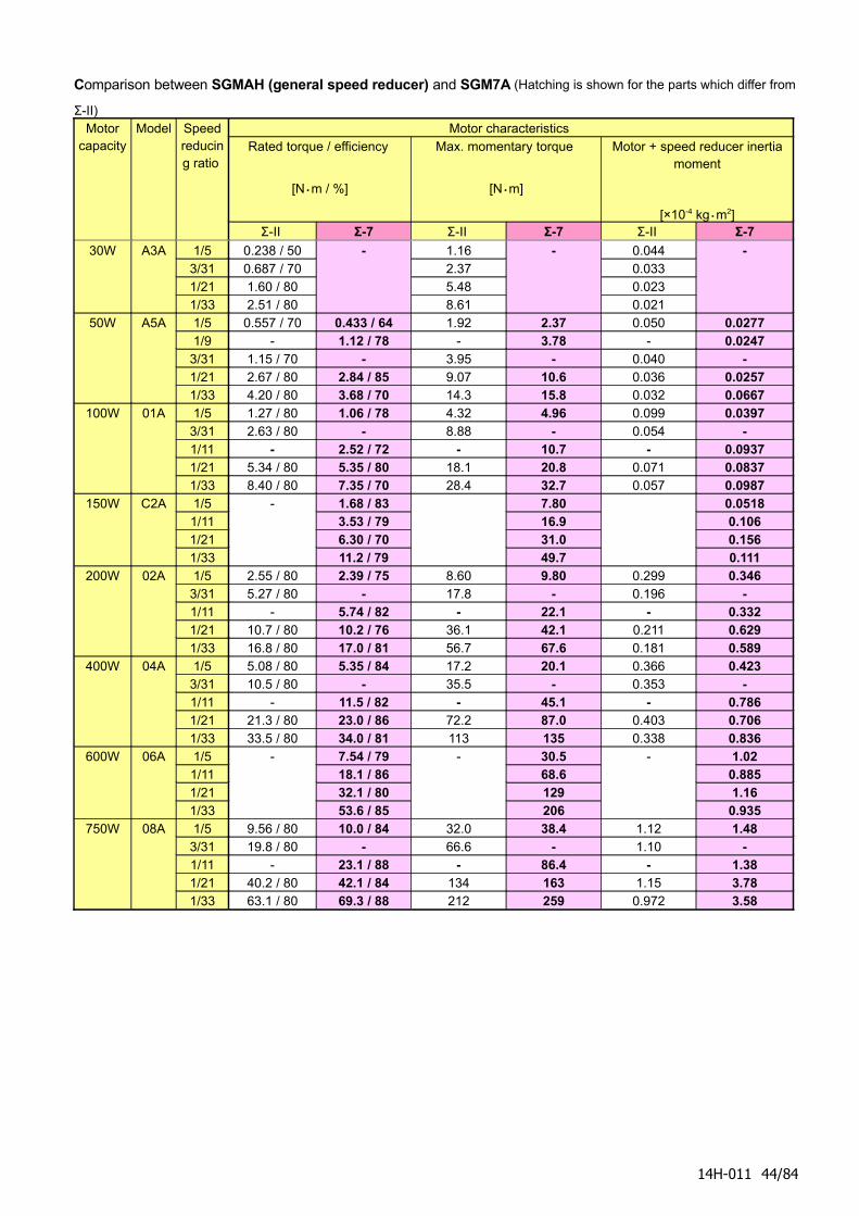
Comparison between SGMAH (general speed reducer) and SGM7A (Hatching is shown for the parts which differ from
Σ-II) Motor
capacity Model Speed
reducing ratio
Motor characteristics Rated torque / efficiency
[N・m / %]
Max. momentary torque
[N・m]
Motor + speed reducer inertia moment
[×10-4 kg・m2]Σ-II Σ-7 Σ-II Σ-7 Σ-II Σ-7
30W A3A 1/5 0.238 / 503/31 0.687 / 701/21 1.60 / 801/33 2.51 / 80
- 1.162.375.488.61
- 0.0440.0330.0230.021
-
50W A5A 1/5 0.557 / 70 0.433 / 64 1.92 2.37 0.050 0.02771/9 - 1.12 / 78 - 3.78 - 0.0247
3/31 1.15 / 70 - 3.95 - 0.040 -1/21 2.67 / 80 2.84 / 85 9.07 10.6 0.036 0.02571/33 4.20 / 80 3.68 / 70 14.3 15.8 0.032 0.0667
100W 01A 1/5 1.27 / 80 1.06 / 78 4.32 4.96 0.099 0.03973/31 2.63 / 80 - 8.88 - 0.054 -1/11 - 2.52 / 72 - 10.7 - 0.09371/21 5.34 / 80 5.35 / 80 18.1 20.8 0.071 0.08371/33 8.40 / 80 7.35 / 70 28.4 32.7 0.057 0.0987
150W C2A 1/51/111/211/33
- 1.68 / 833.53 / 796.30 / 7011.2 / 79
7.8016.931.049.7
0.05180.1060.1560.111
200W 02A 1/5 2.55 / 80 2.39 / 75 8.60 9.80 0.299 0.3463/31 5.27 / 80 - 17.8 - 0.196 -1/11 - 5.74 / 82 - 22.1 - 0.3321/21 10.7 / 80 10.2 / 76 36.1 42.1 0.211 0.6291/33 16.8 / 80 17.0 / 81 56.7 67.6 0.181 0.589
400W 04A 1/5 5.08 / 80 5.35 / 84 17.2 20.1 0.366 0.4233/31 10.5 / 80 - 35.5 - 0.353 -1/11 - 11.5 / 82 - 45.1 - 0.7861/21 21.3 / 80 23.0 / 86 72.2 87.0 0.403 0.7061/33 33.5 / 80 34.0 / 81 113 135 0.338 0.836
600W 06A 1/51/111/211/33
- 7.54 / 7918.1 / 8632.1 / 8053.6 / 85
- 30.568.6129206
- 1.020.8851.16
0.935750W 08A 1/5 9.56 / 80 10.0 / 84 32.0 38.4 1.12 1.48
3/31 19.8 / 80 - 66.6 - 1.10 -1/11 - 23.1 / 88 - 86.4 - 1.381/21 40.2 / 80 42.1 / 84 134 163 1.15 3.781/33 63.1 / 80 69.3 / 88 212 259 0.972 3.58
14H-011 44/84
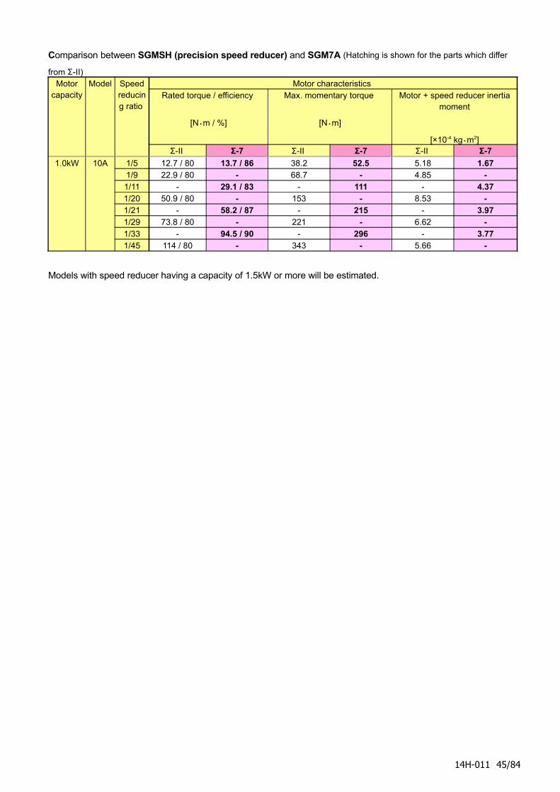
Comparison between SGMSH (precision speed reducer) and SGM7A (Hatching is shown for the parts which differ
from Σ-II) Motor
capacity Model Speed
reducing ratio
Motor characteristics Rated torque / efficiency
[N・m / %]
Max. momentary torque
[N・m]
Motor + speed reducer inertia moment
[×10-4 kg・m2]Σ-II Σ-7 Σ-II Σ-7 Σ-II Σ-7
1.0kW 10A 1/5 12.7 / 80 13.7 / 86 38.2 52.5 5.18 1.671/9 22.9 / 80 - 68.7 - 4.85 -1/11 - 29.1 / 83 - 111 - 4.371/20 50.9 / 80 - 153 - 8.53 -1/21 - 58.2 / 87 - 215 - 3.971/29 73.8 / 80 - 221 - 6.62 -1/33 - 94.5 / 90 - 296 - 3.771/45 114 / 80 - 343 - 5.66 -
Models with speed reducer having a capacity of 1.5kW or more will be estimated.
14H-011 45/84
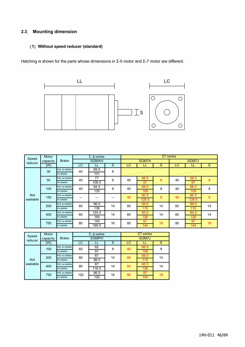
2.3. Mounting dimension
(1) Without speed reducer (standard)
Hatching is shown for the parts whose dimensions in Σ-II motor and Σ-7 motor are different.
[W] LC LL S LC LL S LC LL SNot av ailable 69.5Av ailable 101Not av ailable 77 56.5 56.5Av ailable 108.5 97 97Not av ailable 94.5 68.5 68.5Av ailable 135 109 109Not av ailable 80.5 80.5Av ailable 128.5 128.5Not av ailable 96.5 69.5 69.5Av ailable 136 110 110Not av ailable 124.5 85.5 85.5Av ailable 164 126 126Not av ailable 145 97 97Av ailable 189.5 144 144
[W] LC LL S LC LL SNot av ailable 62 68.5Av ailable 91 109Not av ailable 67 69.5Av ailable 98.5 110Not av ailable 87 85.5Av ailable 118.5 126Not av ailable 86.5 97Av ailable 120 144
80 19
60 14
60 14
40 8
14
19
40
40
40
8
8
400 80 14
750 120 16
200 80
40
40
60
60
80
Σ7 series
14
8
16
8
8
Notavailable
100 60 8
SGMPH SGM7J
14
14
14
19
60
60
80
Speedreducer
Motorcapacity Brake
Σ-Ⅱseries
60 14
60 14
750 80
400
40 6
- -
40 8
-
40
40 6
Notavailable
30
50
150
200
8100
SGM7JΣ7 series
Speedreducer
BrakeΣ-ⅡseriesMotor
capacity SGMAH SGM7A
14H-011 46/84
LL LC
S
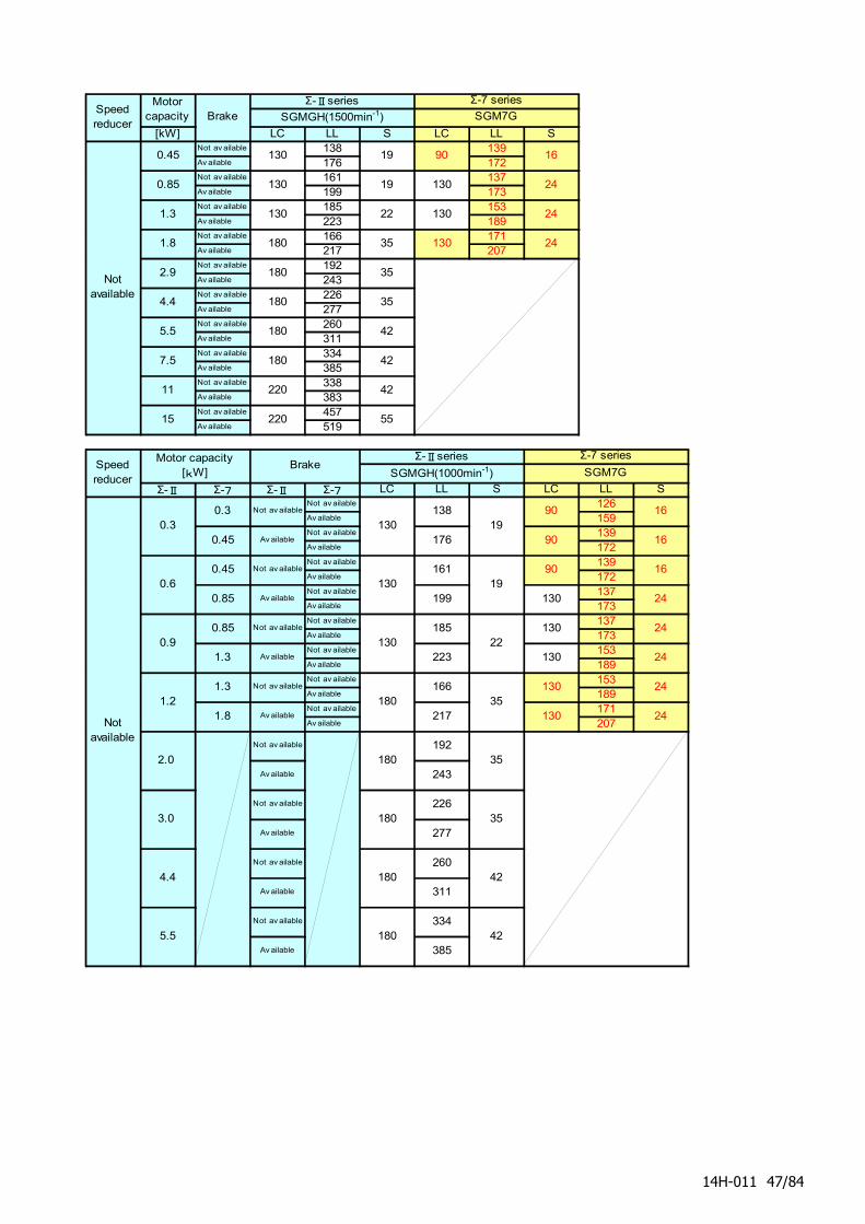
[kW] LC LL S LC LL SNot av ailable 138 139Av ailable 176 172Not av ailable 161 137Av ailable 199 173Not av ailable 185 153Av ailable 223 189Not av ailable 166 171Av ailable 217 207Not av ailable 192Av ailable 243Not av ailable 226Av ailable 277Not av ailable 260Av ailable 311Not av ailable 334Av ailable 385Not av ailable 338Av ailable 383Not av ailable 457Av ailable 519
Σ-Ⅱ Σ-7 Σ-Ⅱ Σ-7 LC LL S LC LL SNot av ailable 126Av ailable 159Not av ailable 139Av ailable 172Not av ailable 139Av ailable 172Not av ailable 137Av ailable 173Not av ailable 137Av ailable 173Not av ailable 153Av ailable 189Not av ailable 153Av ailable 189Not av ailable 171Av ailable 207
130
130
130
180
180
180
185
223
166
217
180
180
226
277
0.9
1.2
2.0
3.0
4.4
5.5
260
311
334Not av ailable
1.3 Not av ailable
1.8 Av ailable
Av ailable
0.3
0.6
0.3
0.45
0.45
0.85
385
19
19
22
35
35
35
42
192
243
Σ-7 series
SGM7G
16
16
0.85
1.3
138
176
161
199
Not av ailable
Av ailable
42
Av ailable
90
90
90
Σ-Ⅱseries
SGMGH(1000min-1)
16
24
24
24
Av ailable
130
130
130
130
130
24
24
Brake
Not av ailable
Not av ailable
Av ailable
Not av ailable
Av ailable
Not av ailable
Av ailable
Not av ailable
Speedreducer
Motorcapacity Brake
Σ-Ⅱseries Σ-7 series
SGMGH(1500min-1) SGM7G
7.5 180 42
5.5 180 42
15 220 55
11 220 42
130 24
1.8 180 35 130 24
1.3 130 22
24
90 16
Speedreducer
0.45 130 19
Notavailable
0.85 130 19 130
Notavailable
Motor capacity[kW]
4.4 180 35
2.9 180 35
14H-011 47/84
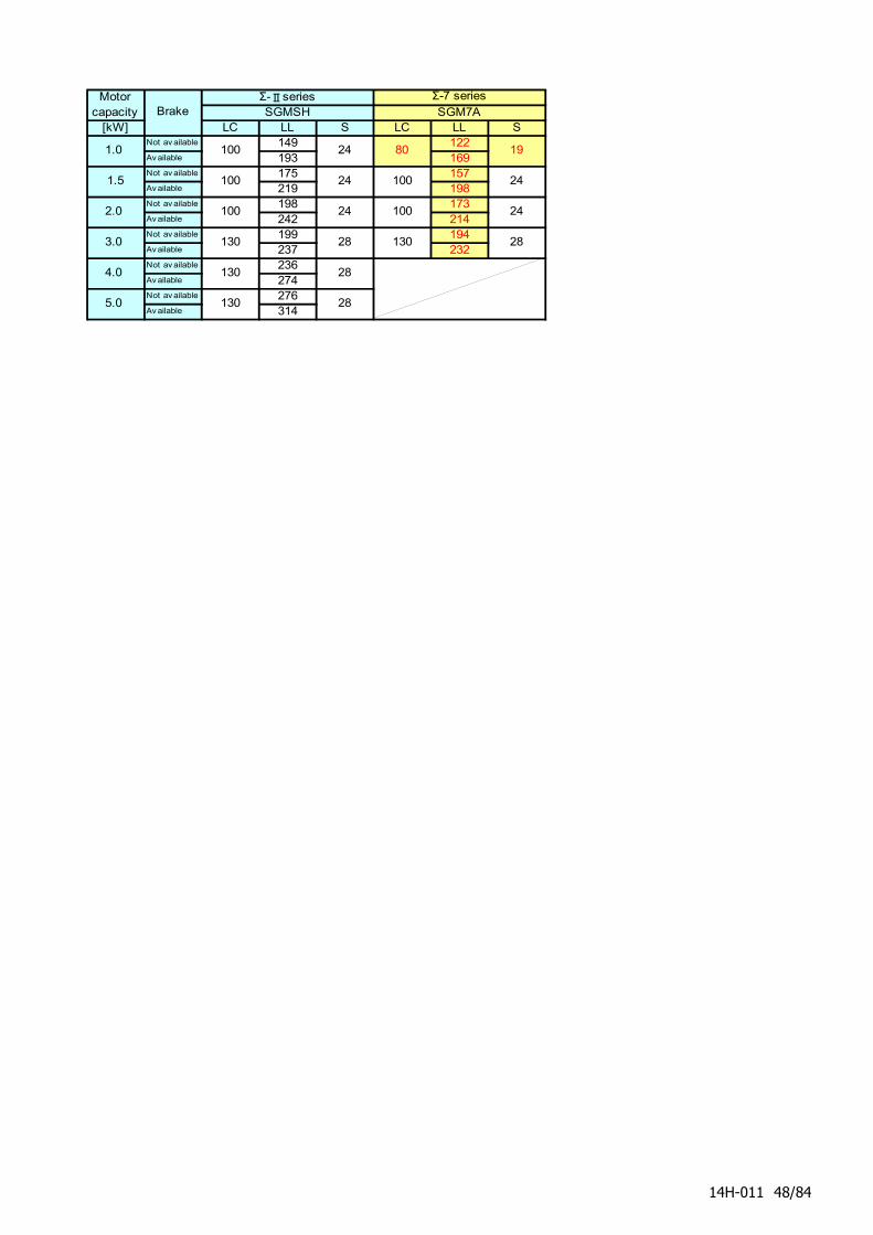
[kW] LC LL S LC LL SNot av ailable 149 122Av ailable 193 169Not av ailable 175 157Av ailable 219 198Not av ailable 198 173Av ailable 242 214Not av ailable 199 194Av ailable 237 232Not av ailable 236Av ailable 274Not av ailable 276Av ailable 314
100 24
5.0 130 28
4.0 130 28
80 19
3.0 130 28 130 28
1.0
Σ-Ⅱseries Σ-7 seriesSGMSH
100
Motorcapacity Brake SGM7A
24
2.0 100 24 100 24
1.5 100 24
14H-011 48/84
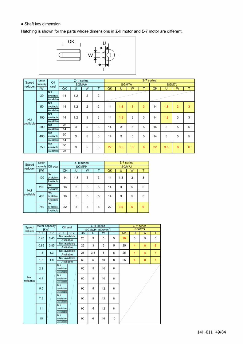
● Shaft key dimension
Hatching is shown for the parts whose dimensions in Σ-II motor and Σ-7 motor are different.
[W] QK U W T QK U W T QK U W TNotavailable
Available
Notavailable
Available
Notavailable
Available
Notavailable
20Available 14Notavailable
20
Available 14Notavailable
30
Available 25
30
50
200
750
Σ-Ⅱseries
2
400 5
Σ-7 seriesSGMAH SGM7A SGM7J
Speedreducer
Motorcapacity
Oilseal
Notavailable
14 1.2 2
14 2 14 31.2 2 14 3
100 14 3 14 3 14 3
3
53 5
5
66
14 5
14 5
5
22 66
3 5
1.8
1.8
3.55 22
5 14
14
3
3 5
3 5
3 5
1.2 3
3
3.5
3 5
1.8 3
1.8 3
[W] QK U W T QK U W TNotavailable
Available
NotavailableAvailable
Notavailable
Available
Notavailable
Available3.5 6 6
Notavailable
22
1.8 3
200
100 14
750 3
1.8
16
400 16 3
Σ-7 series
3
Speedreducer
Motorcapacity Oil seal
Σ-ⅡseriesSGMPH SGM7J
3 5 55 14
5 5 22
5
3 5 5 14 3 5 5
3 3 14
Σ-Ⅱ Σ-7 Σ-Ⅱ Σ-7 QK U W T QK U W T
Notavailable
Available
Notavailable
Available
Notavailable
Available
Notavailable
Available
Notavailable
Available
Notavailable
Available
Speedreducer
Σ-Ⅱ series Σ-7 seriesSGMGH(1500min-1) SGM7G
3
Notavailable
0.45 25 3
15 90 6
Available5 5
7.5 90 5 12 8
5 5 20
16 10
11 90 5 12 8
2.9 60
Motor capacity[kW]
0.45
Oil seal
Not available
90
5 10 84.4 60
5 10 8
0.85 0.85Not available
25
5 12 85.5
4 8 8Available
3 5 5 25
7Available
3.5 6 6 25Not available
25
1.8 1.8Not available
60
4 81.3 1.3
4 8 7Available
5 10 8 25
14H-011 49/84
T
W
UQK
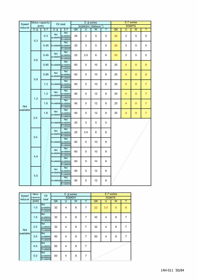
Σ-Ⅱ Σ-7 Σ-Ⅱ Σ-7 QK U W T QK U W TNot
available
Available
Notavailable
Available
Notavailable
Available
Notavailable
Available
Notavailable
Available
Notavailable
Available
Notavailable
Available
Notavailable
Available
Notavailable
Available
Notavailable
Available
Notavailable
Available
Notavailable
Available
Notavailable
Available
Notavailable
Available
Notavailable
Available
Notavailable
Available
[kW] QK U W T QK U W TNotavailable
Available
Notavailable
Available
Notavailable
Available
Notavailable
Available
Notavailable
Available
Notavailable
Available
5 10 8
10 8
8
8
8
60
3.0
0.45 25
5.0 50 4 8
32 4 8
4.0 50 4
6
SGMGH(1500min-1)
5 5
5 5
3
25 3.5 6 6
20 3
5
3 5 5
3 5 55
SGM7GOil sealSpeed
reducer
Motor capacity[kW]
Notavailable
0.3
20
20
0.3 25 3 5
7
Σ-Ⅱseries Σ-7 series
8
7
5 10 8
5 10 8
5 12 8
7
32 4 8
5
6
25
5 10
6
3.0 50 4 8 7 50 4
4
4
0.45 25 3 5
0.85 60
3.5 6
0.6
3.5
5 12 8
60
60
90
22
60
4 8 8
60 5 10 25 4 8 8
Notavailable
1.0 32 4 8 7
81.5
2.0
32
90 5 12Not
available
Speedreducer
Motorcapacity
Oilseal
Σ-ⅡseriesSGMSH
Notavailable
2.0
8
90 5 12 8
90
Available
Notavailable
Available
Notavailable
Available
Notavailable
Available
Available
Notavailable
Available
Available
Notavailable
Available
Notavailable
90
25
4.4
5.5
0.85
1.3
1.3
1.8
1.8
0.9
1.2
25 4 8 7
25 4 8 7
7
32
8 7
25 4 8 75 12
8 7
7
25 4
Σ-7 seriesSGM7A
8 7
14H-011 50/84
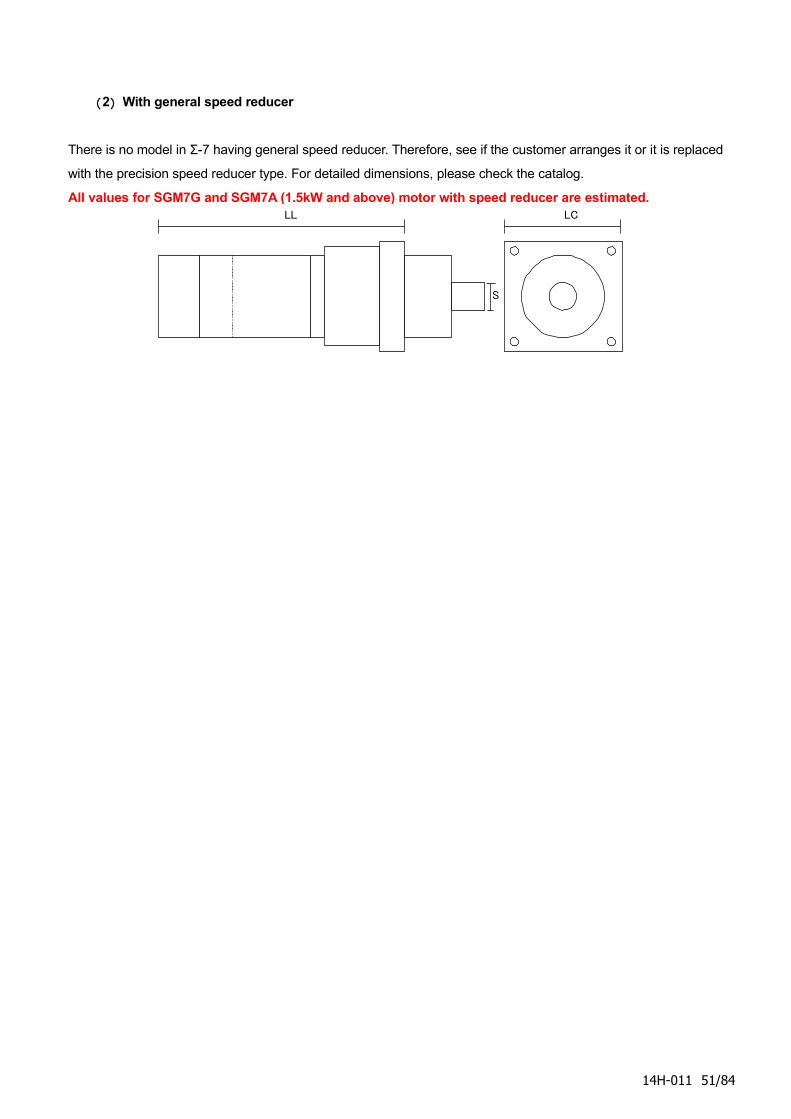
(2) With general speed reducer
There is no model in Σ-7 having general speed reducer. Therefore, see if the customer arranges it or it is replaced
with the precision speed reducer type. For detailed dimensions, please check the catalog.
All values for SGM7G and SGM7A (1.5kW and above) motor with speed reducer are estimated.LL LC
S
14H-011 51/84
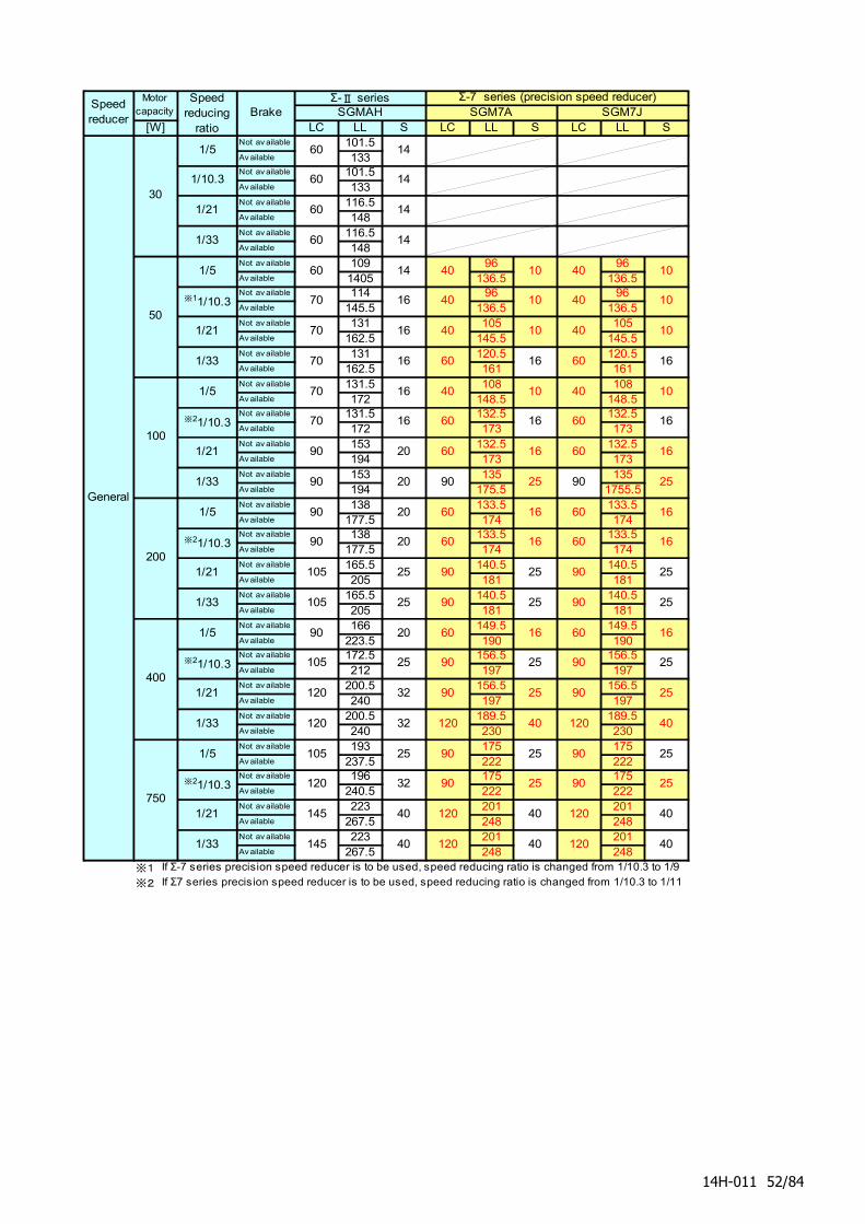
[W] LC LL S LC LL S LC LL SNot av ailable 101.5Av ailable 133Not av ailable 101.5Av ailable 133Not av ailable 116.5Av ailable 148Not av ailable 116.5Av ailable 148Not av ailable 109 96 96Av ailable 1405 136.5 136.5Not av ailable 114 96 96Av ailable 145.5 136.5 136.5Not av ailable 131 105 105Av ailable 162.5 145.5 145.5Not av ailable 131 120.5 120.5Av ailable 162.5 161 161Not av ailable 131.5 108 108Av ailable 172 148.5 148.5Not av ailable 131.5 132.5 132.5Av ailable 172 173 173Not av ailable 153 132.5 132.5Av ailable 194 173 173Not av ailable 153 135 135Av ailable 194 175.5 1755.5Not av ailable 138 133.5 133.5Av ailable 177.5 174 174Not av ailable 138 133.5 133.5Av ailable 177.5 174 174Not av ailable 165.5 140.5 140.5Av ailable 205 181 181Not av ailable 165.5 140.5 140.5Av ailable 205 181 181Not av ailable 166 149.5 149.5Av ailable 223.5 190 190Not av ailable 172.5 156.5 156.5Av ailable 212 197 197Not av ailable 200.5 156.5 156.5Av ailable 240 197 197Not av ailable 200.5 189.5 189.5Av ailable 240 230 230Not av ailable 193 175 175Av ailable 237.5 222 222Not av ailable 196 175 175Av ailable 240.5 222 222Not av ailable 223 201 201Av ailable 267.5 248 248Not av ailable 223 201 201Av ailable 267.5 248 248
※1 If Σ-7 series precision speed reducer is to be used, speed reducing ratio is changed from 1/10.3 to 1/9
※2 If Σ7 series precision speed reducer is to be used, speed reducing ratio is changed from 1/10.3 to 1/11
Motorcapacity Brake
Σ-Ⅱ series Σ-7 series (precision speed reducer)SGMAH SGM7A SGM7J
90 20
Speedreducer
25
60 16 60 16
90 25 90 25
40
145 40 120 40 120 40
145 40 120
※21/10.3
1/21 40 120
90 25 90105 25
90 25
1/33
Speedreducing
ratio
1/21
1/33
※21/10.3
1/5
1/33
1/5
32120 120 40
120 32 90 25
25
120 40
1/5 105 25 90 25 90 25
10
90 25
※11/10.3 70 16
1/21
120 32 90
1/33 70 16 60 16 60
70 16 40 10
40 10
16
70 16 40
60 16 60 16
40 10
60 16
1/33 90 20
1001/21 90 20
※21/10.3 70 16
60 16 60 16
90 25 90 25
200
1/5 90 20
105 25
1/21 105 25
16 60 16※21/10.3 90 20
1/10.3 60 14
1/5 60 14
14
301/21 60 14
General
40 10 401/5 60 14
50
1/33 60
90 25 90 25
10
40 10 40 10
60
400
750
60 16
14H-011 52/84
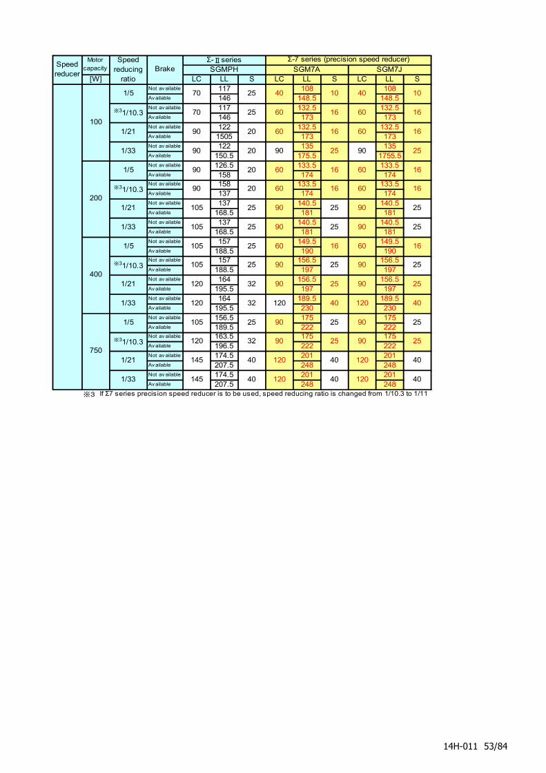
[W] LC LL S LC LL S LC LL SNot av ailable 117 108 108Av ailable 146 148.5 148.5Not av ailable 117 132.5 132.5Av ailable 146 173 173Not av ailable 122 132.5 132.5Av ailable 1505 173 173Not av ailable 122 135 135Av ailable 150.5 175.5 1755.5Not av ailable 126.5 133.5 133.5Av ailable 158 174 174Not av ailable 158 133.5 133.5Av ailable 137 174 174Not av ailable 137 140.5 140.5Av ailable 168.5 181 181Not av ailable 137 140.5 140.5Av ailable 168.5 181 181Not av ailable 157 149.5 149.5Av ailable 188.5 190 190Not av ailable 157 156.5 156.5Av ailable 188.5 197 197Not av ailable 164 156.5 156.5Av ailable 195.5 197 197Not av ailable 164 189.5 189.5Av ailable 195.5 230 230Not av ailable 156.5 175 175Av ailable 189.5 222 222Not av ailable 163.5 175 175Av ailable 196.5 222 222Not av ailable 174.5 201 201Av ailable 207.5 248 248Not av ailable 174.5 201 201Av ailable 207.5 248 248
※3 If Σ7 series precision speed reducer is to be used, speed reducing ratio is changed from 1/10.3 to 1/11
16
40
6016 1660
90
60
90 90
60
60
25
90
60 60
90
1660
9025 25
120 120
90
9025
90 9025
40 40
9025 2590
120
Speedreducer
Motorcapacity
Speedreducing
ratio
Σ-Ⅱseries Σ-7 series (precision speed reducer)SGMPH SGM7ABrake SGM7J
6016 16
40
120120
2590
120
100
1/5 70 25 10 10
※31/10.3 70 25 60
16
1/33 90 20 25 25
1/21 90 20 16
200
1/5 90 20
※31/10.3 90 20
1/21 105 25
400
1/5 105 25 16 16
※31/10.3 105 25
90
40
1/21 120 32 25
251/33 105 25 25
120 32
1/21 145 40
25
1/33 120 32 40
401/33 145 40 40
750
1/5 105 25
※31/10.3
14H-011 53/84
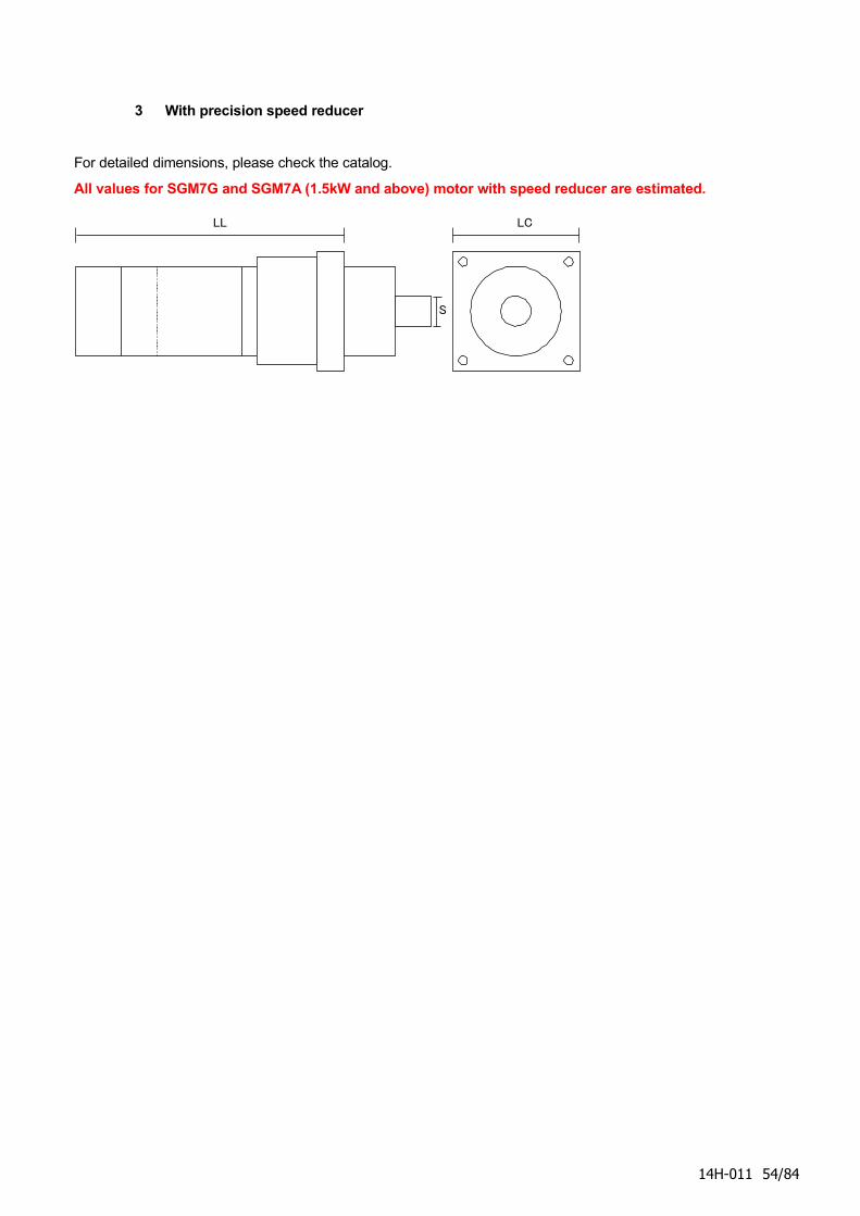
3 With precision speed reducer
For detailed dimensions, please check the catalog.
All values for SGM7G and SGM7A (1.5kW and above) motor with speed reducer are estimated.
LL LC
S
14H-011 54/84
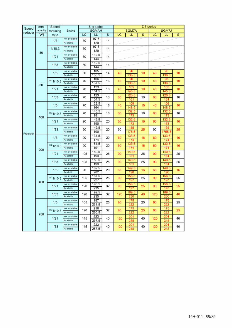
[W] LC LL S LC LL S LC LL SNot av ailable 97.5Av ailable 129Not av ailable 97.5Av ailable 129Not av ailable 112.5Av ailable 144Not av ailable 112.5Av ailable 144Not av ailable 105 96 96Av ailable 136.5 136.5 136.5Not av ailable 106 96 96Av ailable 137.5 136.5 136.5Not av ailable 123 105 105Av ailable 154.5 145.5 145.5Not av ailable 123 120.5 120.5Av ailable 154.5 161 161Not av ailable 123.5 108 108Av ailable 164 148.5 148.5Not av ailable 140.5 132.5 132.5Av ailable 181 173 173Not av ailable 149.5 132.5 132.5Av ailable 190 173 173Not av ailable 149.5 135 135Av ailable 190 175.5 1755.5Not av ailable 134.5 133.5 133.5Av ailable 174 174 174Not av ailable 151.5 133.5 133.5Av ailable 191 174 174Not av ailable 159.5 140.5 140.5Av ailable 199 181 181Not av ailable 159.5 140.5 140.5Av ailable 199 181 181Not av ailable 162.5 149.5 149.5Av ailable 202 190 190Not av ailable 187.5 156.5 156.5Av ailable 227 197 197Not av ailable 195.5 156.5 156.5Av ailable 235 197 197Not av ailable 199.5 189.5 189.5Av ailable 235 230 230Not av ailable 187 175 175Av ailable 231.5 222 222Not av ailable 216 175 175Av ailable 260.5 222 222Not av ailable 223 201 201Av ailable 267.5 248 248Not av ailable 223 201 201Av ailable 267.5 248 248
Motorcapacity Brake
Σ-Ⅱseries Σ-7 seriesSGMAH SGM7A SGM7J
Speedreducer
105 25
25 90 25
1/21 105 25
60 16 60 1690 20
120 40
145 40 120 40
145 40 120 40
120 40
90 25
90 25
90 25
1/33
Speedreducing
ratio
1/21
1/33
※21/10.3
1/5
1/33
1/5
※21/10.3
1/21
1/21
120 32
1/5 105 25
120 32
120 32
90 25
120 40
90 25
120
90 25
40 10
1/33 70 16 60 16 60 16
10
161/21 90 20100
60 16 60
40
※21/10.3 16 60 16
200
60 16
1/33 90 20
601/5 90 20
105 25 90
16 6020
1/10.3 60 14
1/5 60 14
※21/10.3 90
1/21 60 14
60
70 16 40
70
70 40
70
1/33 60 14
16
※11/10.3 16
Precision
40 10 401/5 60 14
50
30
16
90 25 90 25
90 25 90 25
16
60 16
10
40 10 40 10
1010
400
750
40
90 25
90 25
14H-011 55/84
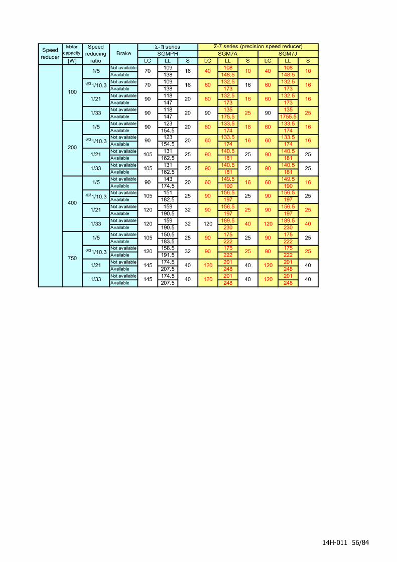
[W] LC LL S LC LL S LC LL SNot available 109 108 108Available 138 148.5 148.5Not available 109 132.5 132.5Available 138 173 173Not available 118 132.5 132.5Available 147 173 173Not available 118 135 135Available 147 175.5 1755.5Not available 123 133.5 133.5Available 154.5 174 174Not available 123 133.5 133.5Available 154.5 174 174Not available 131 140.5 140.5Available 162.5 181 181Not available 131 140.5 140.5Available 162.5 181 181Not available 143 149.5 149.5Available 174.5 190 190Not available 151 156.5 156.5Available 182.5 197 197Not available 159 156.5 156.5Available 190.5 197 197Not available 159 189.5 189.5Available 190.5 230 230Not available 150.5 175 175Available 183.5 222 222Not available 158.5 175 175Available 191.5 222 222Not available 174.5 201 201Available 207.5 248 248Not available 174.5 201 201Available 207.5 248 248
16
40
6016 16
6016 1660
90
60
90 90
60
60
25
90
60 60
90
1660
9025 25
120 120
90
9025
90 9025
40
9025 2590
120
Speedreducer
Motorcapacity
Speedreducing
ratio
Σ-Ⅱseries Σ-7 series (precision speed reducer)SGMPH SGM7ABrake SGM7J
120120
2590
120
100
1/5 70
40
16 10 10
※31/10.3 70 16 60
40
16
1/33 90 20 25 25
1/21 90 20 16
200
1/5 90 20
※31/10.3 90 20
1/21 105 25
400
1/5 90 20 16 16
※31/10.3 105 25
90
40
1/21 120 32 25
251/33 105 25 25
120 32
1/21 145 40
25
1/33 120 32 40
401/33 145 40 40
750
1/5 105 25
※31/10.3
14H-011 56/84
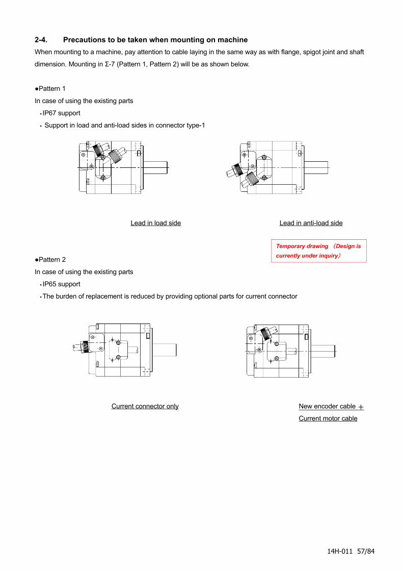
2-4. Precautions to be taken when mounting on machine
When mounting to a machine, pay attention to cable laying in the same way as with flange, spigot joint and shaft
dimension. Mounting in Σ-7 (Pattern 1, Pattern 2) will be as shown below.
●Pattern 1
In case of using the existing parts
・IP67 support
・ Support in load and anti-load sides in connector type-1
Lead in load side Lead in anti-load side
●Pattern 2
In case of using the existing parts
・IP65 support
・The burden of replacement is reduced by providing optional parts for current connector
Current connector only New encoder cable +
Current motor cable
14H-011 57/84
Temporary drawing (Design is
currently under inquiry)
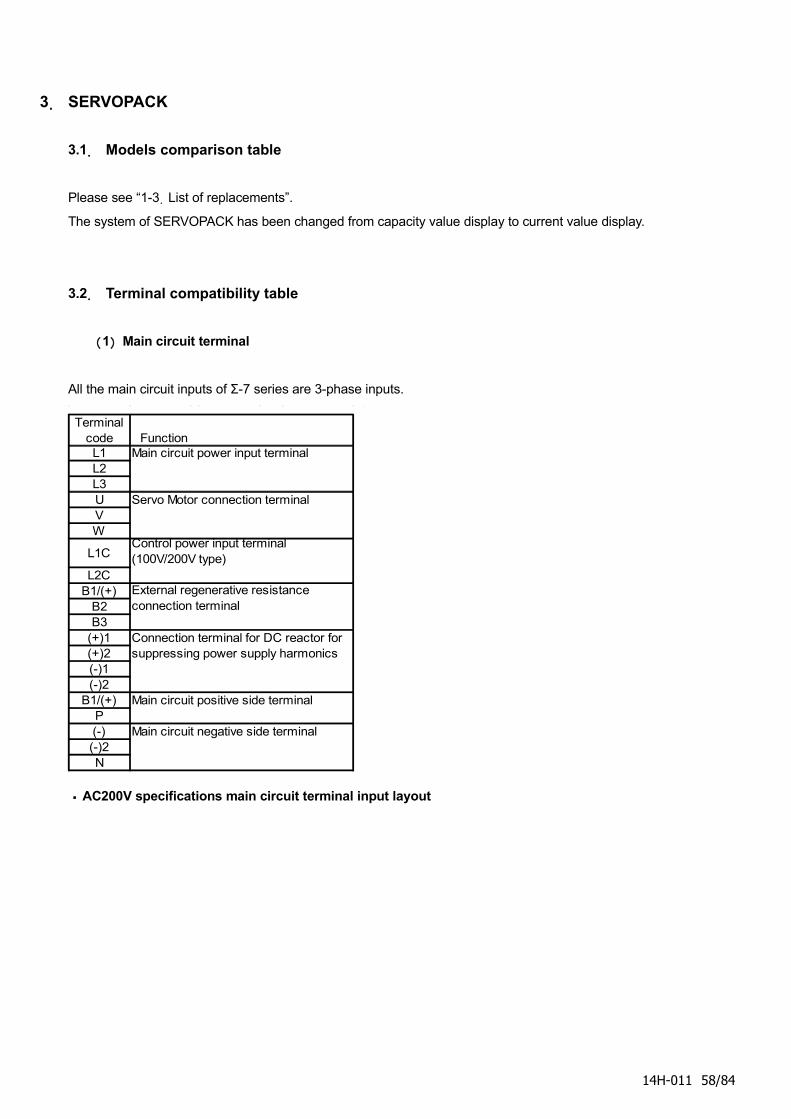
3. SERVOPACK
3.1. Models comparison table
Please see “1-3.List of replacements”.
The system of SERVOPACK has been changed from capacity value display to current value display.
3.2. Terminal compatibility table
(1) Main circuit terminal
All the main circuit inputs of Σ-7 series are 3-phase inputs.
Terminalcode FunctionL1 Main circuit power input terminalL2L3U Servo Motor connection terminalVW
L1C
L2CB1/(+)
B2B3
(+)1(+)2(-)1(-)2
B1/(+) Main circuit positive side terminalP(-) Main circuit negative side terminal(-)2N
Control power input terminal(100V/200V type)
External regenerative resistanceconnection terminal
Connection terminal for DC reactor forsuppressing power supply harmonics
・AC200V specifications main circuit terminal input layout
14H-011 58/84
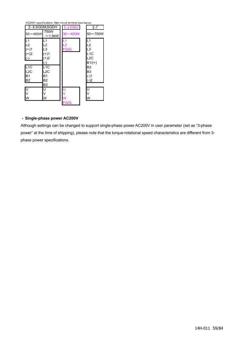
AC200V specif ications: Main circuit terminal input layout
Σ-ⅡSGDJ Σ-7
50~400W 750W ~1.5kW
30~400W 50~750W
L1 L1 L1 L1L2 L2 L2 L2(+)1 L3 FG/G L3(+)2 (+)1 L1C(-) (+)2 L2C
(-) B1/(+)L1C L1C B2L2C L2C B3B1 B1 (-)1B2 B2 (-)2
B3U U U UV V V VW W W W
FG/G
Σ-ⅡSGDM,SGDH
・Single-phase power AC200V
Although settings can be changed to support single-phase power AC200V in user parameter (set as “3-phase
power” at the time of shipping), please note that the torque-rotational speed characteristics are different from 3-
phase power specifications.
14H-011 59/84
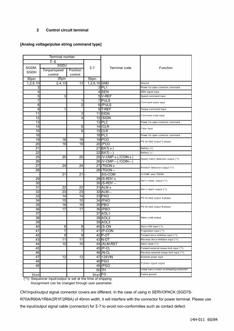
2 Control circuit terminal
[Analog voltage/pulse string command type]
Torque/speedcontrol
Positioncontrol
50pin 50pin1,2,6,10 2,4,13 13 1,2,6,10 GND Ground
3 3 PL1 Power f or open corrector command
4 4 SEN SEN signal input
5 3 5 V-REF Speed command input
7 1 7 PULS8 2 8 /PULS9 1 9 T-REF Torque command input
11 3 11 SIGN12 4 12 /SIGN13 13 PL2 Power f or open corrector command
14 5 14 /CLR15 6 15 CLR18 18 PL3 Power f or open corrector command
19 18 18 19 PCO20 19 19 20 /PCO21 21 BAT(+) Battery (+)
22 22 BAT(-) Battery (-)
25 20 20 25 /V-CMP+(./COIN+)26 26 /V-CMP-(./COIN-)27 24 24 27 /TGON+28 28 /TGON-
- 21 21 - SG-COM /V-CMP- and /TGON-
29 29 /S-RDY+30 30 /S-RDY-31 22 22 31 ALM+32 23 23 32 ALM-33 14 14 33 PAO34 15 15 34 /PAO35 16 16 35 PBO36 17 17 36 /PBO37 37 AOL138 38 AOL239 39 AOL340 8 8 40 /S-ON Serv o ON input (*1)
41 7 7 41 /P-CON P-operation input (*1)
42 9 9 42 P-OT Forward driv e inhibition input (*1)
43 11 11 43 N-OT Rev erse driv e inhibition input (*1)
44 10 10 44 /ALM-RST Alarm reset (*1)
45 45 /P-CL Forward external torque limit input (*1)
46 46 /N-CL Rev erse external torque limit input (*1)
47 12 12 47 +24VIN External power input
48 48 PSO49 49 /PSO
50 TH Linear serv o motor ov erheating protection
inputShell Shell FG Frame ground
(*1): Sequencer input/output is set at the time of shipping.
Assignment can be changed through user parameter.
S-phase signal output
Rotation detection output (*1)
Serv o ready output (*1)
Serv o alarm output (*1)
PG div ided output A-phase
Command code input
Clear input
PG div ided output C-phase
Speed match detection output (*1)
PG div ided output B-phase
Alarm code output
Terminal number
FunctionTerminal code
Command pulse input
26pin
Σ-7SGDM,SGDH
SGDJΣ-Ⅱ
CN1input/output signal connector covers are different. In the case of using in SERVOPACK (SGD7S-
R70A/R90A/1R6A/2R1F/2R8A) of 40mm width, it will interfere with the connector for power terminal. Please use
the input/output signal cable (connector) for Σ-7 to avoid non-conformities such as contact defect.
14H-011 60/84

Connectors of CN2 encoder and CN5 analog monitor are compatible.
14H-011 61/84
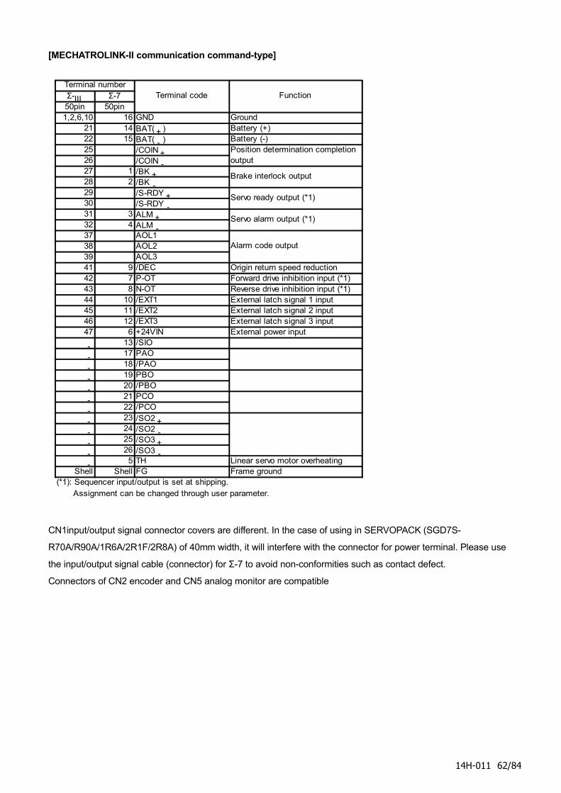
[MECHATROLINK-II communication command-type]
Σ-Ⅲ Σ-750pin 50pin1,2,6,10 16 GND Ground
21 14 BAT(+) Battery (+)22 15 BAT(-) Battery (-)25 /COIN+26 /COIN-27 1 /BK+28 2 /BK-29 /S-RDY+30 /S-RDY-31 3 ALM+32 4 ALM-37 AOL138 AOL239 AOL341 9 /DEC Origin return speed reduction42 7 P-OT Forward drive inhibition input (*1)43 8 N-OT Reverse drive inhibition input (*1)44 10 /EXT1 External latch signal 1 input45 11 /EXT2 External latch signal 2 input46 12 /EXT3 External latch signal 3 input47 6 +24VIN External power input
- 13 /SIO
- 17 PAO
- 18 /PAO
- 19 PBO
- 20 /PBO
- 21 PCO
- 22 /PCO
- 23 /SO2+- 24 /SO2-- 25 /SO3+- 26 /SO3-- 5 TH Linear servo motor overheating
Shell Shell FG Frame ground(*1): Sequencer input/output is set at shipping.
Assignment can be changed through user parameter.
Servo ready output (*1)
Servo alarm output (*1)
Alarm code output
Terminal numberFunctionTerminal code
Position determination completionoutput
Brake interlock output
CN1input/output signal connector covers are different. In the case of using in SERVOPACK (SGD7S-
R70A/R90A/1R6A/2R1F/2R8A) of 40mm width, it will interfere with the connector for power terminal. Please use
the input/output signal cable (connector) for Σ-7 to avoid non-conformities such as contact defect.
Connectors of CN2 encoder and CN5 analog monitor are compatible
14H-011 62/84
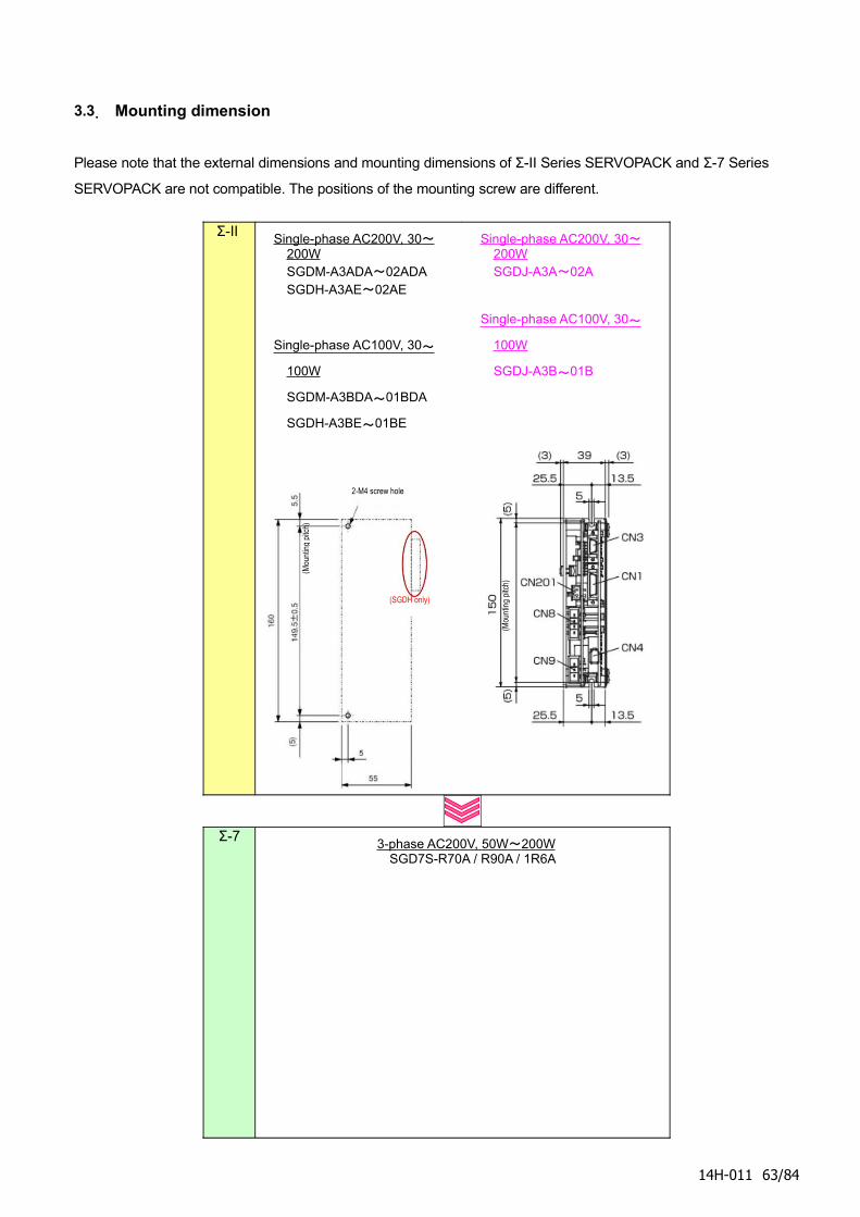
3.3. Mounting dimension
Please note that the external dimensions and mounting dimensions of Σ-II Series SERVOPACK and Σ-7 Series
SERVOPACK are not compatible. The positions of the mounting screw are different.
Σ-II Single-phase AC200V, 30 ~ 200WSGDM-A3ADA~02ADASGDH-A3AE~02AE
Single-phase AC100V, 30 ~
100W
SGDM-A3BDA~01BDA
SGDH-A3BE~01BE
Single-phase AC200V, 30 ~ 200WSGDJ-A3A~02A
Single-phase AC100V, 30 ~
100W
SGDJ-A3B~01B
Σ-73-phase AC200V, 50W ~ 200W
SGD7S-R70A / R90A / 1R6A
14H-011 63/84
2-M4 screw hole
(Mou
ntin
g pi
tch)
(SGDH only)
(Mou
ntin
g pi
tch)
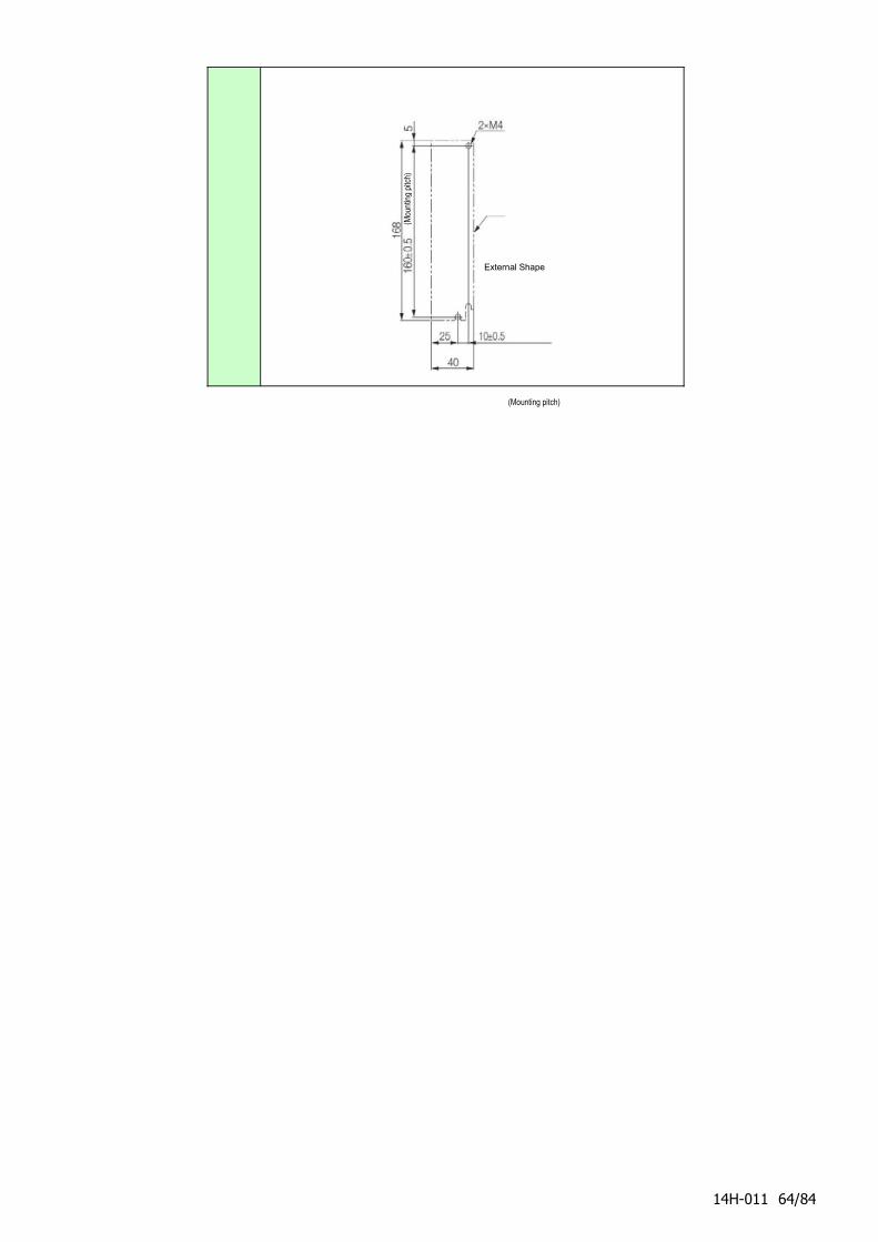
14H-011 64/84
(Mou
ntin
g pi
tch)
(Mounting pitch)
External Shape
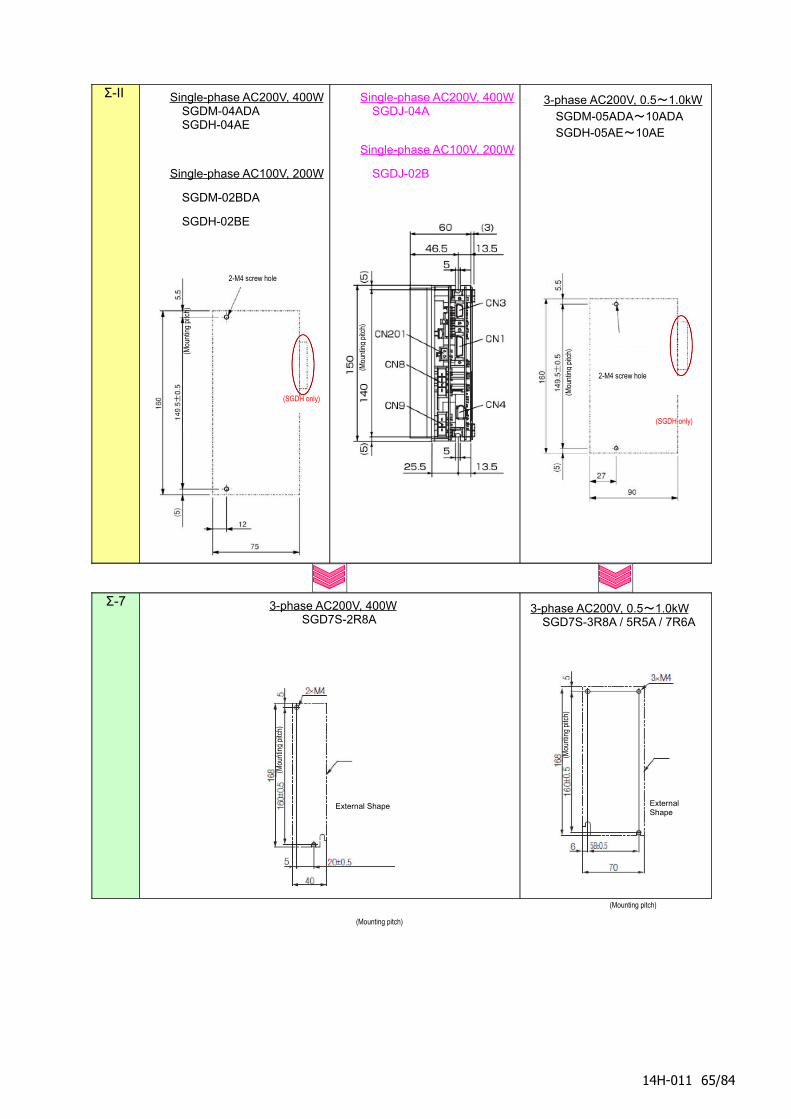
Σ-II Single-phase AC200V, 400WSGDM-04ADASGDH-04AE
Single-phase AC100V, 200W
SGDM-02BDA
SGDH-02BE
Single-phase AC200V, 400WSGDJ-04A
Single-phase AC100V, 200W
SGDJ-02B
3-phase AC200V, 0.5 ~ 1.0kW SGDM-05ADA~10ADASGDH-05AE~10AE
Σ-7 3-phase AC200V, 400WSGD7S-2R8A
3-phase AC200V, 0.5 ~ 1.0kW SGD7S-3R8A / 5R5A / 7R6A
14H-011 65/84
(Mou
ntin
g pi
tch)
(Mounting pitch)
External Shape
(Mou
ntin
g pi
tch)
(Mounting pitch)
External Shape
2-M4 screw hole
(Mou
ntin
g pi
tch)
(SGDH only)
2-M4 screw hole
(Mou
ntin
g pi
tch)
(SGDH only)
(Mou
ntin
g pi
tch)
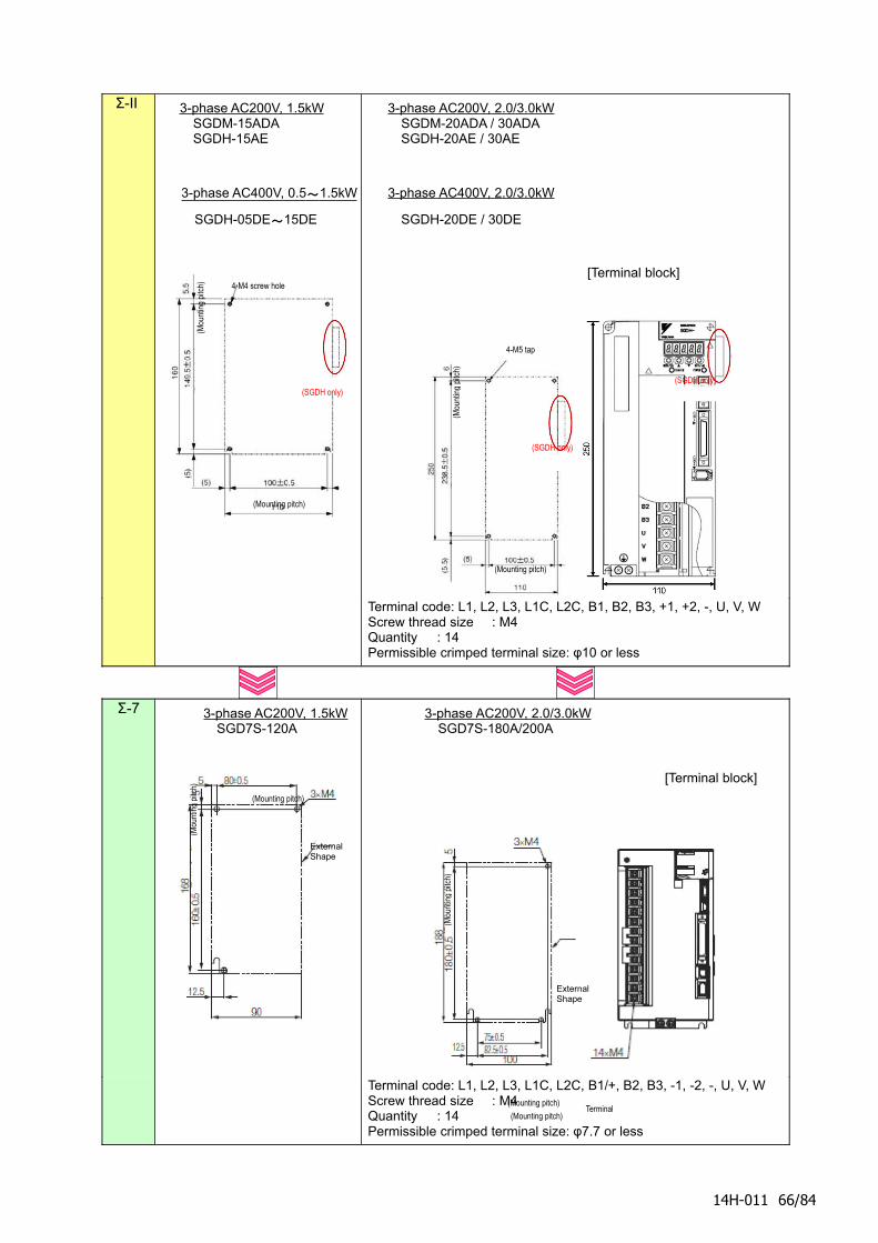
Σ-II 3-phase AC200V, 1.5kWSGDM-15ADASGDH-15AE
3-phase AC400V, 0.5 ~ 1.5kW
SGDH-05DE~15DE
3-phase AC200V, 2.0/3.0kWSGDM-20ADA / 30ADASGDH-20AE / 30AE
3-phase AC400V, 2.0/3.0kW
SGDH-20DE / 30DE
[Terminal block]
Terminal code: L1, L2, L3, L1C, L2C, B1, B2, B3, +1, +2, -, U, V, WScrew thread size : M4 Quantity : 14Permissible crimped terminal size: φ10 or less
Σ-7 3-phase AC200V, 1.5kWSGD7S-120A
3-phase AC200V, 2.0/3.0kWSGD7S-180A/200A
[Terminal block]
Terminal code: L1, L2, L3, L1C, L2C, B1/+, B2, B3, -1, -2, -, U, V, WScrew thread size : M4 Quantity : 14Permissible crimped terminal size: φ7.7 or less
14H-011 66/84
(Mou
ntin
g pi
tch)
(Mounting pitch)
4-M4 screw hole
(SGDH only)
4-M5 tap
(Mou
ntin
g pi
tch)
(Mounting pitch)
(SGDH only)
(SGDH only)
(Mou
ntin
g pi
tch)
(Mounting pitch)
External Shape
(Mou
ntin
g pi
tch)
(Mounting pitch)
External Shape
(Mounting pitch)Terminal
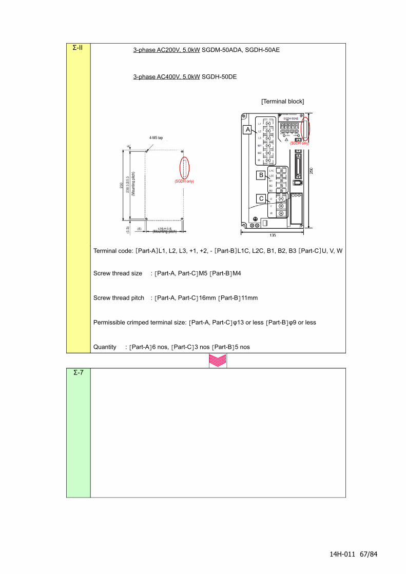
Σ-II 3-phase AC200V, 5.0kW SGDM-50ADA, SGDH-50AE
3-phase AC400V, 5.0kW SGDH-50DE
[Terminal block]
Terminal code: [Part-A]L1, L2, L3, +1, +2, - [Part-B]L1C, L2C, B1, B2, B3 [Part-C]U, V, W
Screw thread size : [Part-A, Part-C]M5 [Part-B]M4
Screw thread pitch : [Part-A, Part-C]16mm [Part-B]11mm
Permissible crimped terminal size: [Part-A, Part-C]φ13 or less [Part-B]φ9 or less
Quantity : [Part-A]6 nos, [Part-C]3 nos [Part-B]5 nos
Σ-7
14H-011 67/84
(Mou
ntin
g pi
tch)
4-M5 tap
(SGDH only)
(Mounting pitch)
(SGDH only)
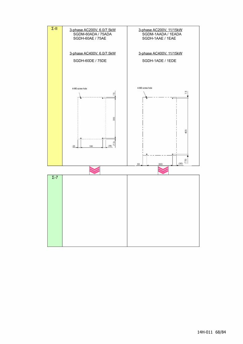
Σ-II 3-phase AC200V, 6.0/7.5kWSGDM-60ADA / 75ADASGDH-60AE / 75AE
3-phase AC400V, 6.0/7.5kW
SGDH-60DE / 75DE
3-phase AC200V, 11/15kWSGDM-1AADA / 1EADASGDH-1AAE / 1EAE
3-phase AC400V, 11/15kW
SGDH-1ADE / 1EDE
Σ-7
14H-011 68/84
4-M6 screw hole 4-M6 screw hole
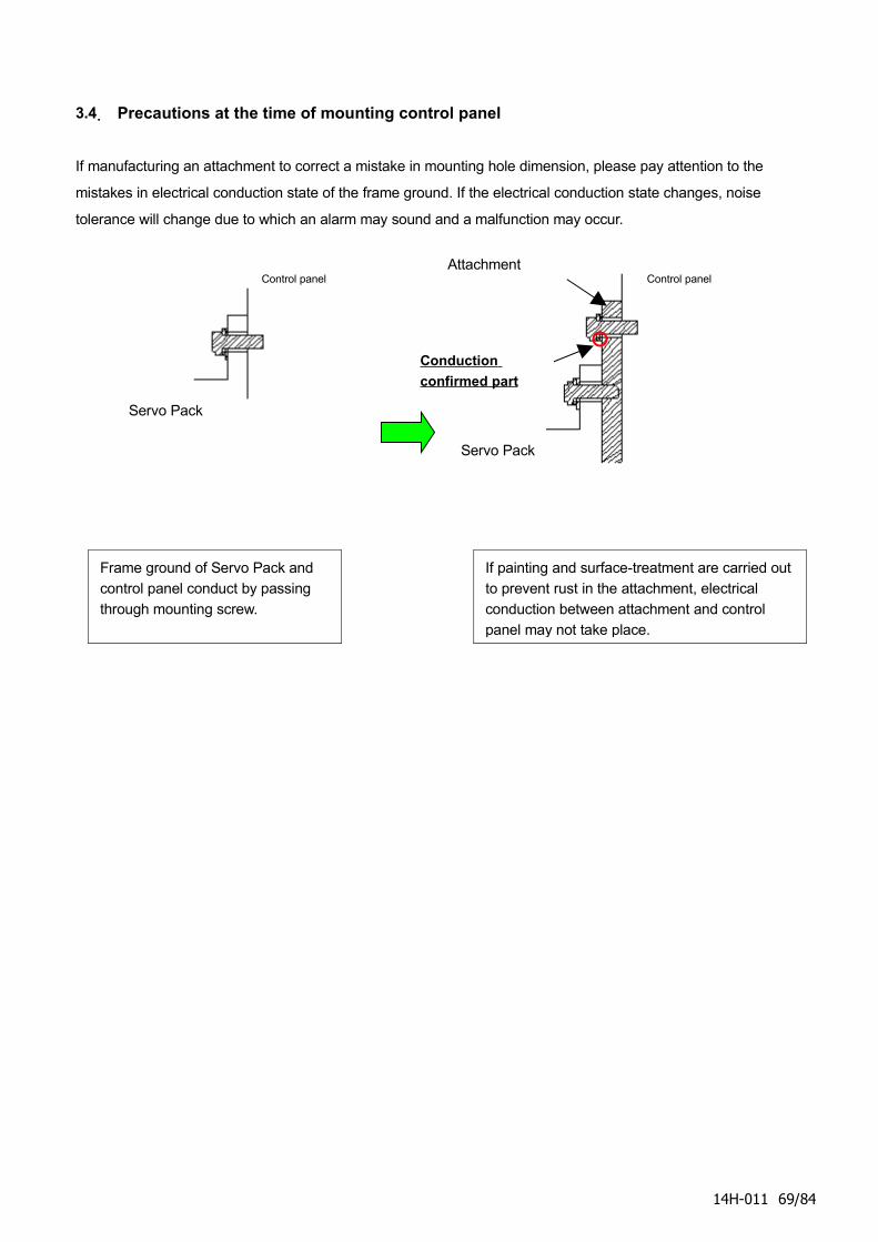
3.4. Precautions at the time of mounting control panel
If manufacturing an attachment to correct a mistake in mounting hole dimension, please pay attention to the
mistakes in electrical conduction state of the frame ground. If the electrical conduction state changes, noise
tolerance will change due to which an alarm may sound and a malfunction may occur.
14H-011 69/84
Control panel
Servo Pack
Control panel
Servo Pack
Attachment
Frame ground of Servo Pack and
control panel conduct by passing
through mounting screw.
If painting and surface-treatment are carried out
to prevent rust in the attachment, electrical
conduction between attachment and control
panel may not take place.
Conduction
confirmed part
4. Cable and peripheral equipment
14H-011 70/84
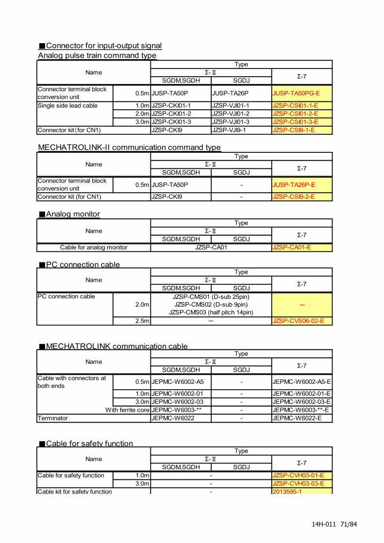
■Connector for input-output signalAnalog pulse train command type
SGDM,SGDH SGDJ
Connector terminal blockconversion unit
0.5m JUSP-TA50P JUSP-TA26P JUSP-TA50PG-E
1.0m JZSP-CKI01-1 JZSP-VJI01-1 JZSP-CSI01-1-E2.0m JZSP-CKI01-2 JZSP-VJI01-2 JZSP-CSI01-2-E3.0m JZSP-CKI01-3 JZSP-VJI01-3 JZSP-CSI01-3-E
JZSP-CKI9 JZSP-VJI9-1 JZSP-CSI9-1-E
MECHATROLINK-II communication command type
SGDM,SGDH SGDJConnector terminal blockconversion unit
0.5m JUSP-TA50P - JUSP-TA26P-E
JZSP-CKI9 - JZSP-CSI9-2-E
■Analog monitor
SGDM,SGDH SGDJJZSP-CA01-E
■PC connection cable
SGDM,SGDH SGDJ
2.0m -
2.5m JZSP-CVS06-02-E
■MECHATROLINK communication cable
SGDM,SGDH SGDJCable with connectors atboth ends
0.5m JEPMC-W6002-A5 - JEPMC-W6002-A5-E
1.0m JEPMC-W6002-01 - JEPMC-W6002-01-E3.0m JEPMC-W6002-03 - JEPMC-W6002-03-E
With ferrite core JEPMC-W6003-** - JEPMC-W6003-**-EJEPMC-W6022 - JEPMC-W6022-E
■Cable for safety function
SGDM,SGDH SGDJCable for safety function 1.0m JZSP-CVH03-01-E
3.0m JZSP-CVH03-03-E2013595-1
Connector kit(for CN1)
Σ-Ⅱ
Name
Connector kit (for CN1)
NameType
Σ-Ⅱ
TypeΣ-Ⅱ
Σ-7
Σ-7
Cable for analog monitor JZSP-CA01
Type
Single side lead cable
NameΣ-7
Σ-Ⅱ
Σ-7
Σ-7
Name
PC connection cable
TypeΣ-Ⅱ
JZSP-CMS01 (D-sub 25pin)JZSP-CMS02 (D-sub 9pin)
JZSP-CMS03 (half pitch 14pin)
-
Σ-7
Name
Terminator
Name
TypeΣ-Ⅱ
Type
---Cable kit for safety function
14H-011 71/84
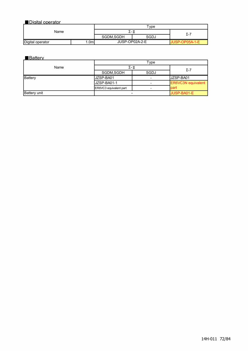
■Digital operator
SGDM,SGDH SGDJDigital operator 1.0m JUSP-OP05A-1-E
■Battery
SGDM,SGDH SGDJ
Battery JZSP-BA01 - JZSP-BA01JZSP-BA01-1 -
ER6VC3 equivalent part -
JUSP-BA01-E
Type
ER6VC3N equivalentpart
Battery unit
Name
Name
Σ-Ⅱ
JUSP-OP02A-2-E
TypeΣ-Ⅱ
-
Σ-7
Σ-7
14H-011 72/84
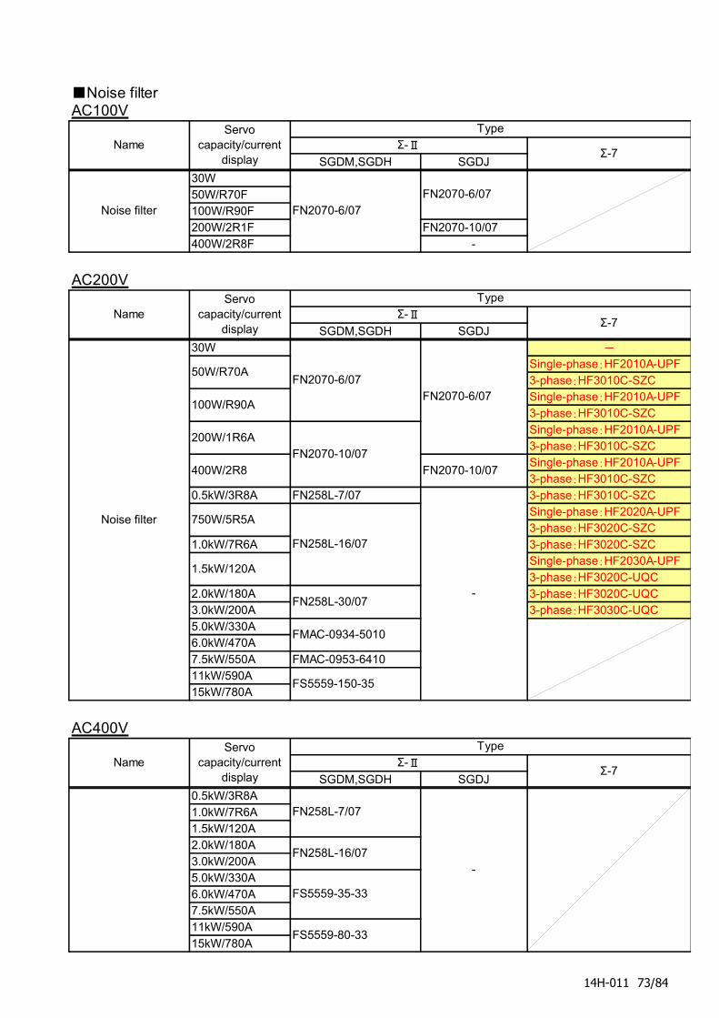
■Noise filterAC100V
SGDM,SGDH SGDJ30W50W/R70F100W/R90F200W/2R1F FN2070-10/07400W/2R8F -
AC200V
SGDM,SGDH SGDJ30W -
Single-phase:HF2010A-UPF3-phase:HF3010C-SZCSingle-phase:HF2010A-UPF3-phase:HF3010C-SZCSingle-phase:HF2010A-UPF3-phase:HF3010C-SZCSingle-phase:HF2010A-UPF3-phase:HF3010C-SZC
0.5kW/3R8A FN258L-7/07 3-phase:HF3010C-SZCSingle-phase:HF2020A-UPF3-phase:HF3020C-SZC
1.0kW/7R6A 3-phase:HF3020C-SZCSingle-phase:HF2030A-UPF3-phase:HF3020C-UQC
2.0kW/180A 3-phase:HF3020C-UQC3.0kW/200A 3-phase:HF3030C-UQC5.0kW/330A6.0kW/470A7.5kW/550A FMAC-0953-641011kW/590A15kW/780A
AC400V
SGDM,SGDH SGDJ0.5kW/3R8A1.0kW/7R6A1.5kW/120A2.0kW/180A3.0kW/200A5.0kW/330A6.0kW/470A7.5kW/550A11kW/590A15kW/780A
FN258L-7/07
100W/R90A
200W/1R6A
FS5559-80-33
-
FN2070-6/07
FN2070-10/07
FMAC-0934-5010
FS5559-150-35
NameServo
capacity/currentdisplay
Type
Noise filter
50W/R70A
FN2070-6/07
Σ-Ⅱ
FN2070-10/07
FN2070-6/07
750W/5R5A
1.5kW/120A
400W/2R8
FN258L-16/07
FN258L-30/07
FS5559-35-33
Σ-7
NameTypeServo
capacity/currentdisplay
NameServo
capacity/currentdisplay
Type
Noise filter
FN258L-16/07
Σ-7
FN2070-6/07
Σ-ⅡΣ-7
-
Σ-Ⅱ
14H-011 73/84
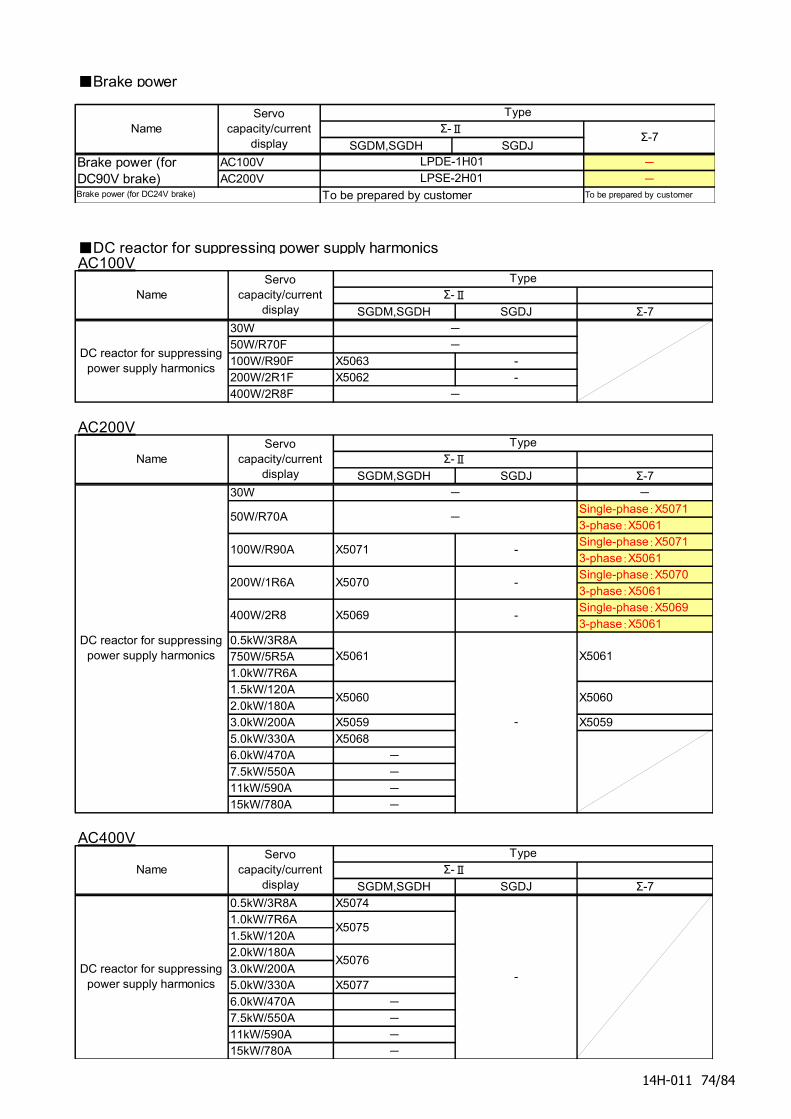
■Brake power
SGDM,SGDH SGDJAC100V -
AC200V -
To be prepared by customer To be prepared by customer
Σ-ⅡNameServo
capacity/currentdisplay
Type
Σ-7
Brake power (for DC24V brake)
LPSE-2H01LPDE-1H01Brake power (for
DC90V brake)
■DC reactor for suppressing power supply harmonicsAC100V
SGDM,SGDH SGDJ Σ-730W50W/R70F100W/R90F X5063 -200W/2R1F X5062 -400W/2R8F
AC200V
SGDM,SGDH SGDJ Σ-730W -
Single-phase:X50713-phase:X5061Single-phase:X50713-phase:X5061Single-phase:X50703-phase:X5061Single-phase:X50693-phase:X5061
0.5kW/3R8A750W/5R5A1.0kW/7R6A1.5kW/120A2.0kW/180A3.0kW/200A X5059 X50595.0kW/330A X50686.0kW/470A -
7.5kW/550A -
11kW/590A -
15kW/780A -
AC400V
SGDM,SGDH SGDJ Σ-70.5kW/3R8A X50741.0kW/7R6A1.5kW/120A2.0kW/180A3.0kW/200A5.0kW/330A X50776.0kW/470A -
7.5kW/550A -
11kW/590A -
15kW/780A -
X5060
X5071
X5070
X5069
-
Σ-Ⅱ
-
-
NameServo
capacity/currentdisplay
Type
200W/1R6A
-
-
NameServo
capacity/currentdisplay
Type
DC reactor for suppressingpower supply harmonics
Σ-Ⅱ
-
-
X5061
X5060
DC reactor for suppressingpower supply harmonics
100W/R90A
400W/2R8
X5061
50W/R70A
-
-
TypeΣ-Ⅱ
DC reactor for suppressingpower supply harmonics
X5075
X5076-
NameServo
capacity/currentdisplay
14H-011 74/84
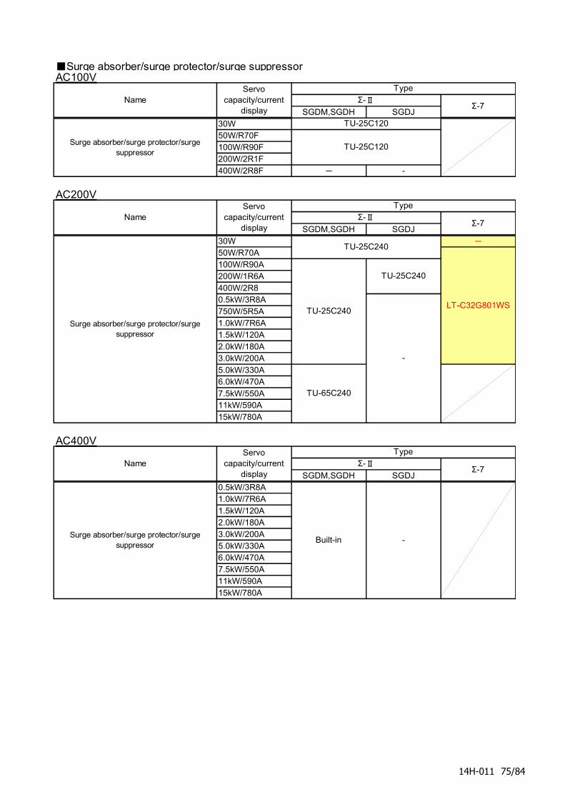
■Surge absorber/surge protector/surge suppressorAC100V
SGDM,SGDH SGDJ30W50W/R70F100W/R90F200W/2R1F400W/2R8F - -
AC200V
SGDM,SGDH SGDJ30W -
50W/R70A100W/R90A200W/1R6A400W/2R80.5kW/3R8A750W/5R5A1.0kW/7R6A1.5kW/120A2.0kW/180A3.0kW/200A5.0kW/330A6.0kW/470A7.5kW/550A11kW/590A15kW/780A
AC400V
SGDM,SGDH SGDJ0.5kW/3R8A1.0kW/7R6A1.5kW/120A2.0kW/180A3.0kW/200A5.0kW/330A6.0kW/470A7.5kW/550A11kW/590A15kW/780A
NameServo
capacity/currentdisplay
Type
Surge absorber/surge protector/surgesuppressor
Built-in
Σ-ⅡΣ-7
-
Surge absorber/surge protector/surgesuppressor
TU-25C240
TU-65C240
LT-C32G801WS
-
TU-25C240
TU-25C240
NameServo
capacity/currentdisplay
TypeΣ-Ⅱ
Σ-7
TU-25C120
NameServo
capacity/currentdisplay
Type
Surge absorber/surge protector/surgesuppressor
Σ-ⅡΣ-7
TU-25C120
14H-011 75/84
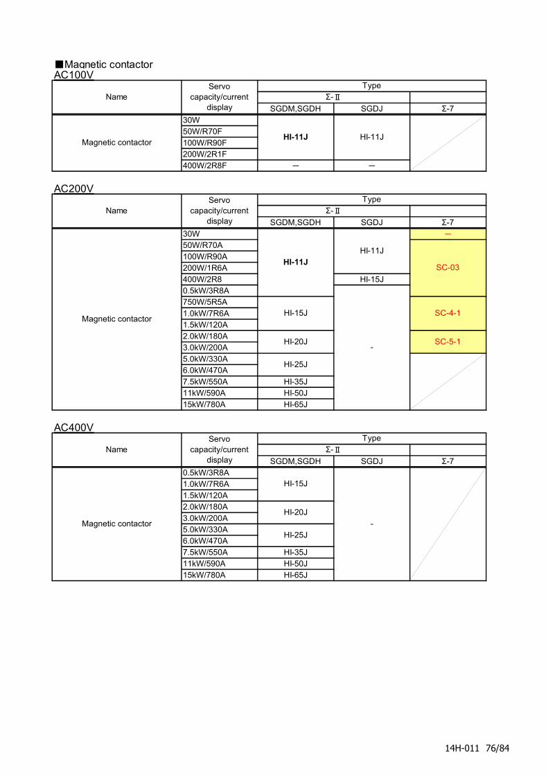
■Magnetic contactorAC100V
SGDM,SGDH SGDJ Σ-730W50W/R70F100W/R90F200W/2R1F400W/2R8F - -
AC200V
SGDM,SGDH SGDJ Σ-730W -
50W/R70A100W/R90A200W/1R6A400W/2R8 HI-15J0.5kW/3R8A750W/5R5A1.0kW/7R6A1.5kW/120A2.0kW/180A3.0kW/200A5.0kW/330A6.0kW/470A7.5kW/550A HI-35J11kW/590A HI-50J15kW/780A HI-65J
AC400V
SGDM,SGDH SGDJ Σ-70.5kW/3R8A1.0kW/7R6A1.5kW/120A2.0kW/180A3.0kW/200A5.0kW/330A6.0kW/470A7.5kW/550A HI-35J11kW/590A HI-50J15kW/780A HI-65J
Σ-Ⅱ
HI-11JHI-11J
HI-15J
HI-20J
HI-25J
-
SC-03
SC-4-1
NameServo
capacity/currentdisplay
Type
Magnetic contactor
HI-11J
Σ-Ⅱ
HI-11J
SC-5-1
NameServo
capacity/currentdisplay
TypeΣ-Ⅱ
NameServo
capacity/currentdisplay
Type
Magnetic contactor
Magnetic contactor
HI-15J
HI-20J
HI-25J-
14H-011 76/84
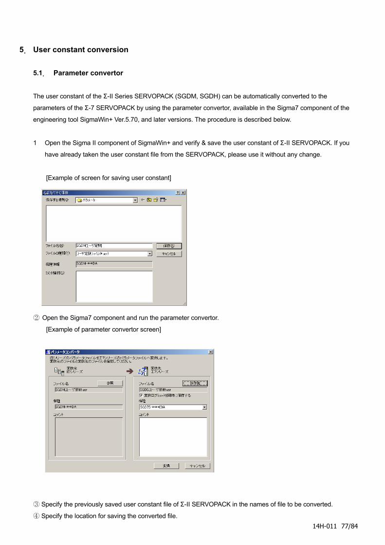
5. User constant conversion
5.1. Parameter convertor
The user constant of the Σ-II Series SERVOPACK (SGDM, SGDH) can be automatically converted to the
parameters of the Σ-7 SERVOPACK by using the parameter convertor, available in the Sigma7 component of the
engineering tool SigmaWin+ Ver.5.70, and later versions. The procedure is described below.
1 Open the Sigma II component of SigmaWin+ and verify & save the user constant of Σ-II SERVOPACK. If you
have already taken the user constant file from the SERVOPACK, please use it without any change.
[Example of screen for saving user constant]
② Open the Sigma7 component and run the parameter convertor.
[Example of parameter convertor screen]
Specify the previously saved user constant file of Σ-II SERVOPACK in the names of file to be converted.③
Specify the location for saving the converted file.④
14H-011 77/84

(Continued on next page)
14H-011 78/84
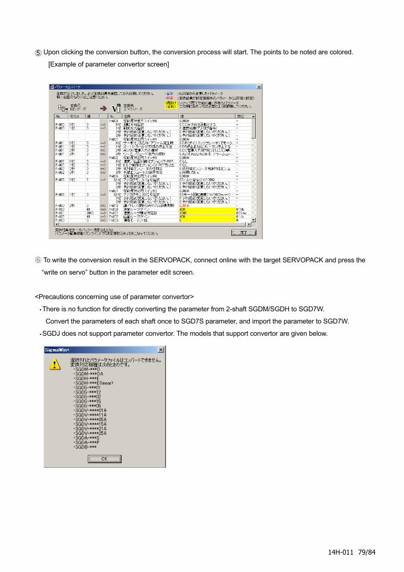
⑤ Upon clicking the conversion button, the conversion process will start. The points to be noted are colored.
[Example of parameter convertor screen]
To write the conversion result in the SERVOPACK, connect online with the target SERVOPACK and press the⑥
“write on servo” button in the parameter edit screen.
<Precautions concerning use of parameter convertor>
・There is no function for directly converting the parameter from 2-shaft SGDM/SGDH to SGD7W.
Convert the parameters of each shaft once to SGD7S parameter, and import the parameter to SGD7W.
・SGDJ does not support parameter convertor. The models that support convertor are given below.
14H-011 79/84
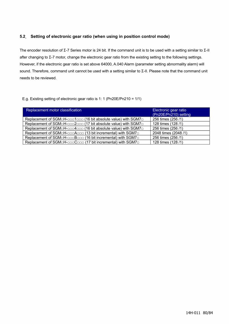
5.2. Setting of electronic gear ratio (when using in position control mode)
The encoder resolution of Σ-7 Series motor is 24 bit. If the command unit is to be used with a setting similar to Σ-II
after changing to Σ-7 motor, change the electronic gear ratio from the existing setting to the following settings.
However, if the electronic gear ratio is set above 64000, A.040 Alarm (parameter setting abnormality alarm) will
sound. Therefore, command unit cannot be used with a setting similar to Σ-II. Please note that the command unit
needs to be reviewed.
E.g. Existing setting of electronic gear ratio is 1: 1 (Pn20E/Pn210 = 1/1)
Replacement motor classification Electronic gear ratio (Pn20E/Pn210) setting
Replacement of SGM□H-□□□1□□□ (16 bit absolute value) with SGM7□ 256 times (256 /1) Replacement of SGM□H-□□□2□□□ (17 bit absolute value) with SGM7□ 128 times (128 /1) Replacement of SGM□H-□□□4□□□ (16 bit absolute value) with SGM7□ 256 times (256 /1) Replacement of SGM□H-□□□A□□□ (13 bit incremental) with SGM7□ 2048 times (2048 /1) Replacement of SGM□H-□□□B□□□ (16 bit incremental) with SGM7□ 256 times (256 /1) Replacement of SGM□H-□□□C□□□ (17 bit incremental) with SGM7□ 128 times (128 /1)
14H-011 80/84
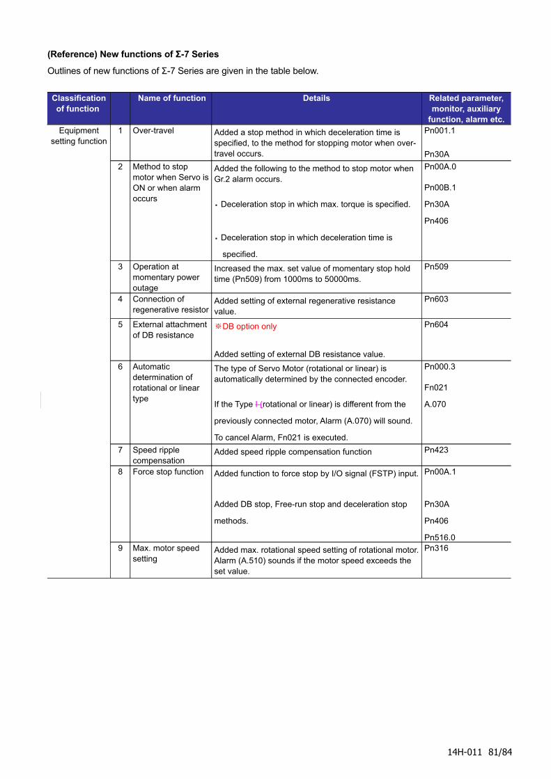
(Reference) New functions of Σ-7 Series
Outlines of new functions of Σ-7 Series are given in the table below.
Classification of function
Name of function Details Related parameter, monitor, auxiliary
function, alarm etc.Equipment
setting function1 Over-travel Added a stop method in which deceleration time is
specified, to the method for stopping motor when over-travel occurs.
Pn001.1
Pn30A
2 Method to stop motor when Servo is ON or when alarm occurs
Added the following to the method to stop motor when Gr.2 alarm occurs.
・ Deceleration stop in which max. torque is specified.
・ Deceleration stop in which deceleration time is
specified.
Pn00A.0
Pn00B.1
Pn30A
Pn406
3 Operation at momentary power outage
Increased the max. set value of momentary stop hold time (Pn509) from 1000ms to 50000ms.
Pn509
4 Connection of regenerative resistor
Added setting of external regenerative resistance value.
Pn603
5 External attachment of DB resistance
DB option only※
Added setting of external DB resistance value.
Pn604
6 Automatic determination of rotational or linear type
The type of Servo Motor (rotational or linear) is automatically determined by the connected encoder.
If the Type I (rotational or linear) is different from the
previously connected motor, Alarm (A.070) will sound.
To cancel Alarm, Fn021 is executed.
Pn000.3
Fn021
A.070
7 Speed ripple compensation
Added speed ripple compensation function Pn423
8 Force stop function Added function to force stop by I/O signal (FSTP) input.
Added DB stop, Free-run stop and deceleration stop
methods.
Pn00A.1
Pn30A
Pn406
Pn516.09 Max. motor speed
settingAdded max. rotational speed setting of rotational motor. Alarm (A.510) sounds if the motor speed exceeds the set value.
Pn316
14H-011 81/84
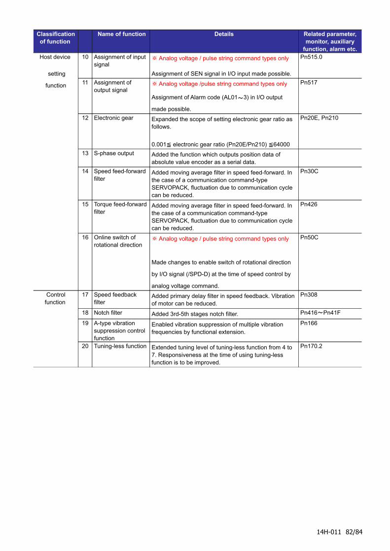
Classification of function
Name of function Details Related parameter, monitor, auxiliary
function, alarm etc.Host device
setting
function
10 Assignment of input signal
Analog voltage / pulse string command types only※
Assignment of SEN signal in I/O input made possible.
Pn515.0
11 Assignment of output signal
Analog voltage /pulse string command types only※
Assignment of Alarm code (AL01~3) in I/O output
made possible.
Pn517
12 Electronic gear Expanded the scope of setting electronic gear ratio as follows.
0.001 electronic gear ratio (Pn20E/Pn210) 64000≦ ≦
Pn20E, Pn210
13 S-phase output Added the function which outputs position data of absolute value encoder as a serial data.
14 Speed feed-forward filter
Added moving average filter in speed feed-forward. In the case of a communication command-type SERVOPACK, fluctuation due to communication cycle can be reduced.
Pn30C
15 Torque feed-forward filter
Added moving average filter in speed feed-forward. In the case of a communication command-type SERVOPACK, fluctuation due to communication cycle can be reduced.
Pn426
16 Online switch of rotational direction
Analog voltage / pulse string command types only※
Made changes to enable switch of rotational direction
by I/O signal (/SPD-D) at the time of speed control by
analog voltage command.
Pn50C
Control function
17 Speed feedback filter
Added primary delay filter in speed feedback. Vibration of motor can be reduced.
Pn308
18 Notch filter Added 3rd-5th stages notch filter. Pn416~Pn41F
19 A-type vibration suppression control function
Enabled vibration suppression of multiple vibration frequencies by functional extension.
Pn166
20 Tuning-less function Extended tuning level of tuning-less function from 4 to 7. Responsiveness at the time of using tuning-less function is to be improved.
Pn170.2
14H-011 82/84
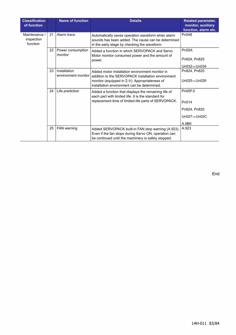
Classification of function
Name of function Details Related parameter, monitor, auxiliary
function, alarm etc. Maintenance /
inspection function
21 Alarm trace Automatically saves operation waveform when alarm sounds has been added. The cause can be determined in the early stage by checking the waveform.
Pn548
22 Power consumption monitor
Added a function in which SERVOPACK and Servo Motor monitor consumed power and the amount of power.
Pn55A
Pn824, Pn825
Un032~Un03423 Installation
environment monitor Added motor installation environment monitor in addition to the SERVOPACK installation environment monitor (equipped in Σ-V). Appropriateness of installation environment can be determined.
Pn824, Pn825
Un025~Un026
24 Life prediction Added a function that displays the remaining life of each part with limited life. It is the standard for replacement time of limited-life parts of SERVOPACK.
Pn00F.0
Pn514
Pn824, Pn825
Un027~Un02C
A.9B025 FAN warning Added SERVOPACK built-in FAN stop warning (A.923).
Even if the fan stops during Servo ON, operation can be continued until the machinery is safely stopped.
A.923
End
14H-011 83/84
Revision history
Revision
No.
Date Details of changes
1st 29-May-2014 English translation of Japanese 2nd version (ET14C-004)
For any query related to these replacement instructions, please get in touch with us at the following address.
Section-2, Technology Promotion Department,
Motion Control Division,
YASKAWA ELECTRIC CORPORATION
14H-011 84/84