INSTALLATION INSTRUCTIONS GB INSTRUCTIONS D’INSTALLATION … · AIR CONDITIONER MULTI VRF ......
22
AIR CONDITIONER MULTI VRF CONDITIONNEUR D’AIR MULTI VRF APARELHOS DE AR CONDICIONADO MULTI VRF ACONDICIONADOR DE AIRE MULTI VRF CONDIZIONATORE D’ARIA MULTI VRF ∫§πª∞∆π™∆π∫√ MULTI VRF INSTALLATION INSTRUCTIONS INSTRUCTIONS D’INSTALLATION INSTRUÇÕES PARA A INSTALAÇÃO INSTRUCCIONES DE INSTALACIÓN ISTRUZIONI PER L’INSTALLAZIONE √¢∏°π∂™ ∂°∫∞∆∞™∆∞™∏™ OUTDOOR UNITS GAS FLOW DISTRIBUTORS UNITÉ EXTÉRIEURES RÉPARTITEURS DE GAZ UNIDADES EXTERIORES DISTRIBUIDORES DE FLUXO DE GÁS UNIDADES EXTERIORES DISTRIBUIDORES DE FLUJO DE GAS UNITÀ ESTERNE DISTRIBUTORI DEL FLUSSO DI GAS ∂•ø∆∂ƒπ∫∂™ ª√¡∞¢∂™ ∫∞∆∞¡∂ª∏∆∂™ ƒ√∏™ ∞∂ƒπ√À 1402100301 GB F P E I G HEAT PUMP POMPE À CHALEUR BOMBA DE CALOR BOMBA DE CALOR POMPA DI CALORE ∞¡∆§π∞ £∂ƒª√∆∏∆∞™ 3-way, 3 voies, 3 vias, 3 vías, 3 vie, 3-∫Ï·‰ˆÓ 4-way, 4 voies, 4 vias, 4 vías, 4 vie, 4-∫Ï·‰ˆÓ 38VVH25 38VV9003 38VV9004
Transcript of INSTALLATION INSTRUCTIONS GB INSTRUCTIONS D’INSTALLATION … · AIR CONDITIONER MULTI VRF ......
AIR CONDITIONER MULTI VRF CONDITIONNEUR D’AIR MULTI VRF APARELHOS DE AR CONDICIONADO MULTI VRF ACONDICIONADOR DE AIRE MULTI VRF CONDIZIONATORE D’ARIA MULTI VRF ∫§πª∞∆π™∆π∫√ MULTI VRF
INSTALLATION INSTRUCTIONS
INSTRUCTIONS D’INSTALLATION
INSTRUÇÕES PARA A INSTALAÇÃO
INSTRUCCIONES DE INSTALACIÓN
ISTRUZIONI PER L’INSTALLAZIONE
√¢∏°π∂™ ∂°∫∞∆∞™∆∞™∏™
OUTDOOR UNITS GAS FLOW DISTRIBUTORSUNITÉ EXTÉRIEURES RÉPARTITEURS DE GAZUNIDADES EXTERIORES DISTRIBUIDORES DE FLUXO DE GÁS UNIDADES EXTERIORES DISTRIBUIDORES DE FLUJO DE GAS UNITÀ ESTERNE DISTRIBUTORI DEL FLUSSO DI GAS∂•ø∆∂ƒπ∫∂™ ª√¡∞¢∂™ ∫∞∆∞¡∂ª∏∆∂™ ƒ√∏™ ∞∂ƒπ√À
1402100301
GB
F
P
E
I
G
HEAT PUMPPOMPE À CHALEURBOMBA DE CALORBOMBA DE CALORPOMPA DI CALORE∞¡∆§π∞ £∂ƒª√∆∏∆∞™
3-way, 3 voies, 3 vias, 3 vías, 3 vie, 3-∫Ï·‰ˆÓ
4-way, 4 voies, 4 vias,4 vías, 4 vie, 4-∫Ï·‰ˆÓ
38VVH25
38VV9003
38VV9004
~ 3 ~
GB
~ 3 ~
INSTALLATION INSTRUCTIONS
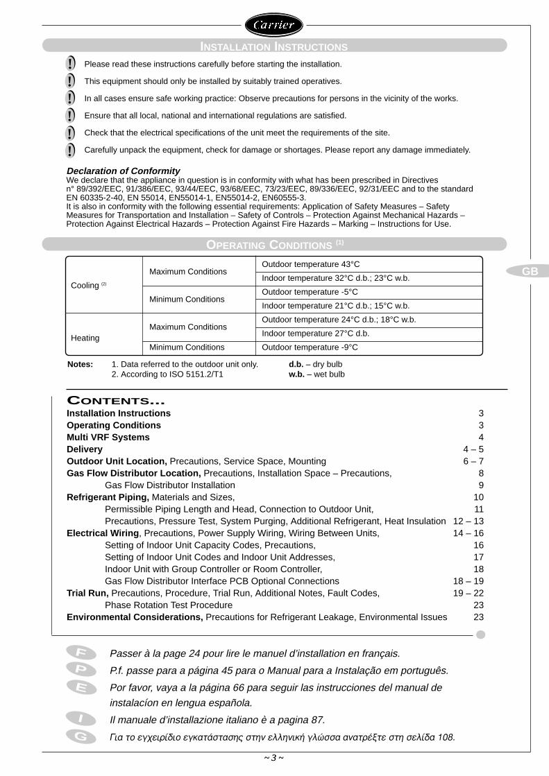
Please read these instructions carefully before starting the installation.
This equipment should only be installed by suitably trained operatives.
In all cases ensure safe working practice: Observe precautions for persons in the vicinity of the works.
Ensure that all local, national and international regulations are satisfied.
Check that the electrical specifications of the unit meet the requirements of the site.
Carefully unpack the equipment, check for damage or shortages. Please report any damage immediately.
OPERATING CONDITIONS (1)
!!!!!!
CONTENTS...Installation Instructions 3Operating Conditions 3Multi VRF Systems 4Delivery 4 – 5Outdoor Unit Location, Precautions, Service Space, Mounting 6 – 7Gas Flow Distributor Location, Precautions, Installation Space – Precautions, 8
Gas Flow Distributor Installation 9Refrigerant Piping, Materials and Sizes, 10
Permissible Piping Length and Head, Connection to Outdoor Unit, 11 Precautions, Pressure Test, System Purging, Additional Refrigerant, Heat Insulation 12 – 13
Electrical Wiring, Precautions, Power Supply Wiring, Wiring Between Units, 14 – 16Setting of Indoor Unit Capacity Codes, Precautions, 16Setting of Indoor Unit Codes and Indoor Unit Addresses, 17Indoor Unit with Group Controller or Room Controller, 18Gas Flow Distributor Interface PCB Optional Connections 18 – 19
Trial Run, Precautions, Procedure, Trial Run, Additional Notes, Fault Codes, 19 – 22Phase Rotation Test Procedure 23
Environmental Considerations, Precautions for Refrigerant Leakage, Environmental Issues 23
E
I
G
P
F Passer à la page 24 pour lire le manuel d’installation en français.
P.f. passe para a página 45 para o Manual para a Instalação em português.
Por favor, vaya a la página 66 para seguir las instrucciones del manual de
instalacíon en lengua española.
Il manuale d’installazione italiano è a pagina 87.
°È· ÙÔ ÂÁ¯ÂÈÚ›‰ÈÔ ÂÁηٿÛÙ·Û˘ ÛÙËÓ ÂÏÏËÓÈ΋ ÁÏÒÛÛ· ·Ó·ÙÚ¤ÍÙ ÛÙË ÛÂÏ›‰· 108.
Outdoor temperature 43°CMaximum Conditions
Indoor temperature 32°C d.b.; 23°C w.b.Cooling (2)
Outdoor temperature -5°CMinimum Conditions
Indoor temperature 21°C d.b.; 15°C w.b.
Outdoor temperature 24°C d.b.; 18°C w.b.Maximum Conditions
Indoor temperature 27°C d.b.HeatingMinimum Conditions Outdoor temperature -9°C
Notes: 1. Data referred to the outdoor unit only. d.b. – dry bulb2. According to ISO 5151.2/T1 w.b. – wet bulb
Declaration of ConformityWe declare that the appliance in question is in conformity with what has been prescribed in Directives n° 89/392/EEC, 91/386/EEC, 93/44/EEC, 93/68/EEC, 73/23/EEC, 89/336/EEC, 92/31/EEC and to the standardEN 60335-2-40, EN 55014, EN55014-1, EN55014-2, EN60555-3.It is also in conformity with the following essential requirements: Application of Safety Measures – SafetyMeasures for Transportation and Installation – Safety of Controls – Protection Against Mechanical Hazards –Protection Against Electrical Hazards – Protection Against Fire Hazards – Marking – Instructions for Use.
~ 4 ~
GB
MULTI VRF SYSTEMS
If more than 4 indoor units are required for an outdoor unit, 2 gas flow distributors should be usedwith T-piece connections.
DELIVERY
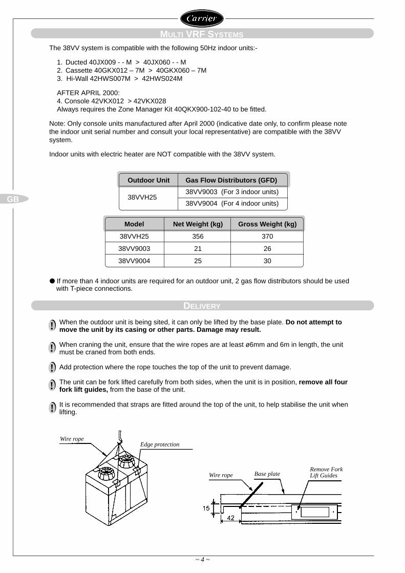
When the outdoor unit is being sited, it can only be lifted by the base plate. Do not attempt tomove the unit by its casing or other parts. Damage may result.
When craning the unit, ensure that the wire ropes are at least ø6mm and 6m in length, the unitmust be craned from both ends.
Add protection where the rope touches the top of the unit to prevent damage.
The unit can be fork lifted carefully from both sides, when the unit is in position, remove all fourfork lift guides, from the base of the unit.
It is recommended that straps are fitted around the top of the unit, to help stabilise the unit whenlifting.
!
!
!
!
!
Wire rope
Wire rope Base plate
Edge protection
Model Net Weight (kg) Gross Weight (kg)
38VVH25 356 370
38VV9003 21 26
38VV9004 25 30
Remove ForkLift Guides
The 38VV system is compatible with the following 50Hz indoor units:-
1. Ducted 40JX009 - - M > 40JX060 - - M2. Cassette 40GKX012 – 7M > 40GKX060 – 7M3. Hi-Wall 42HWS007M > 42HWS024M
AFTER APRIL 2000:4. Console 42VKX012 > 42VKX028Always requires the Zone Manager Kit 40QKX900-102-40 to be fitted.
Note: Only console units manufactured after April 2000 (indicative date only, to confirm please notethe indoor unit serial number and consult your local representative) are compatible with the 38VVsystem.
Indoor units with electric heater are NOT compatible with the 38VV system.
Outdoor Unit Gas Flow Distributors (GFD)
38VVH2538VV9003 (For 3 indoor units)
38VV9004 (For 4 indoor units)
~ 5 ~
GB
DELIVERY
~ 5 ~
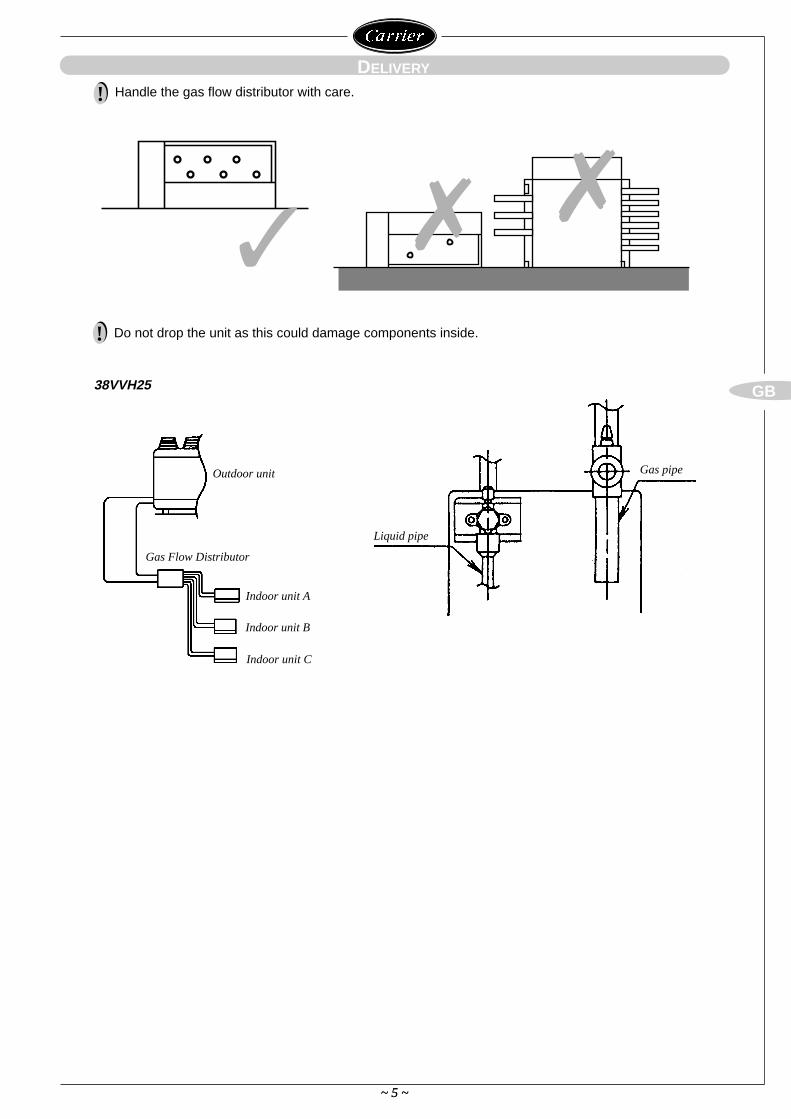
Handle the gas flow distributor with care.!
Do not drop the unit as this could damage components inside.!
Outdoor unit
Gas Flow Distributor
Indoor unit A
Indoor unit B
Indoor unit C
Liquid pipe
Gas pipe
38VVH25
~ 6 ~
GB
10mm 10mm
1530mm
1290mm
834mm
~ 6 ~
OUTDOOR UNIT LOCATION
Service Space
Mounting
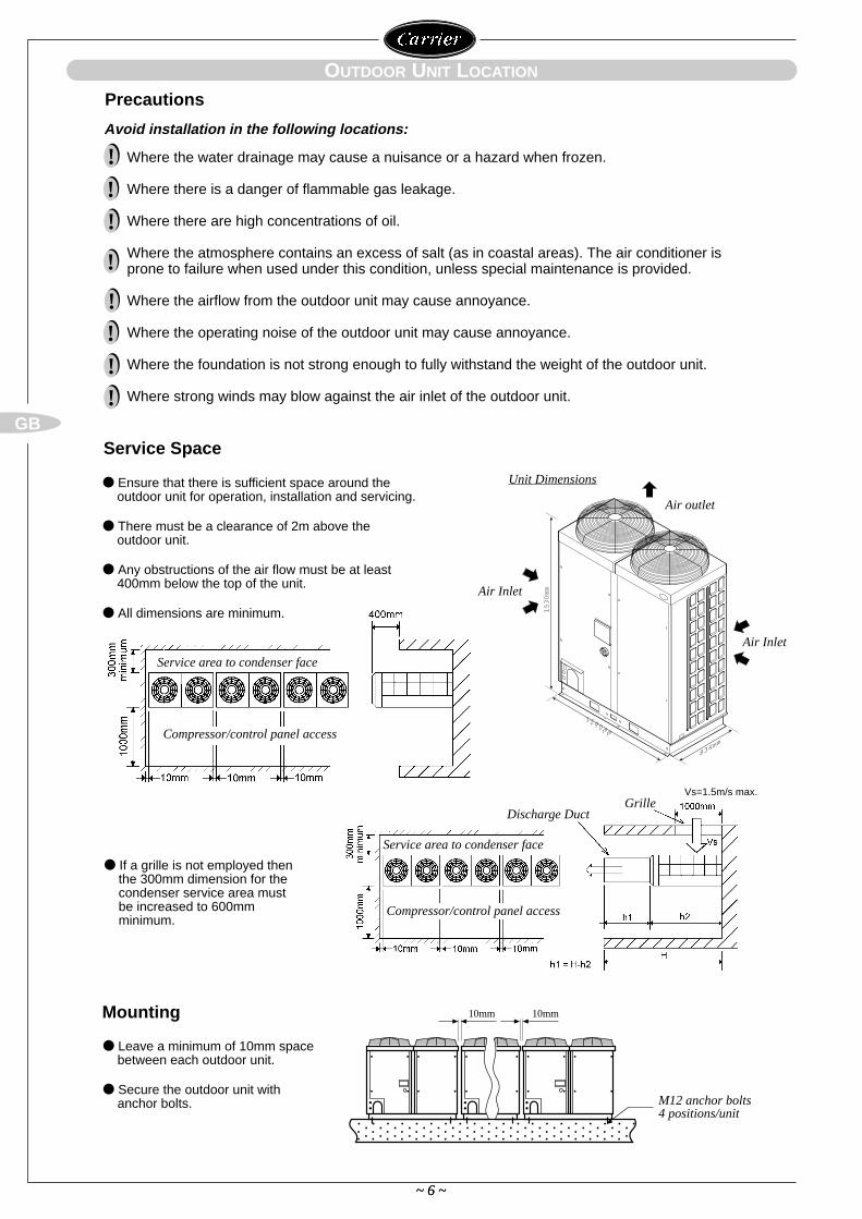
Unit Dimensions
Air outlet
Air Inlet
Vs=1.5m/s max.
Air Inlet
Discharge DuctGrille
M12 anchor bolts 4 positions/unit
Service area to condenser face
Compressor/control panel access
Ensure that there is sufficient space around theoutdoor unit for operation, installation and servicing.
There must be a clearance of 2m above the outdoor unit.
Any obstructions of the air flow must be at least 400mm below the top of the unit.
All dimensions are minimum.
Leave a minimum of 10mm space between each outdoor unit.
Secure the outdoor unit with anchor bolts.
Avoid installation in the following locations:
Where the water drainage may cause a nuisance or a hazard when frozen.
Where there is a danger of flammable gas leakage.
Where there are high concentrations of oil.
Where the atmosphere contains an excess of salt (as in coastal areas). The air conditioner isprone to failure when used under this condition, unless special maintenance is provided.
Where the airflow from the outdoor unit may cause annoyance.
Where the operating noise of the outdoor unit may cause annoyance.
Where the foundation is not strong enough to fully withstand the weight of the outdoor unit.
Where strong winds may blow against the air inlet of the outdoor unit.
Precautions
!!!
!
!!!!
If a grille is not employed thenthe 300mm dimension for thecondenser service area mustbe increased to 600mm minimum.
Service area to condenser face
Compressor/control panel access
~ 7 ~
GB
~ 7 ~
OUTDOOR UNIT LOCATION
Mounting continued
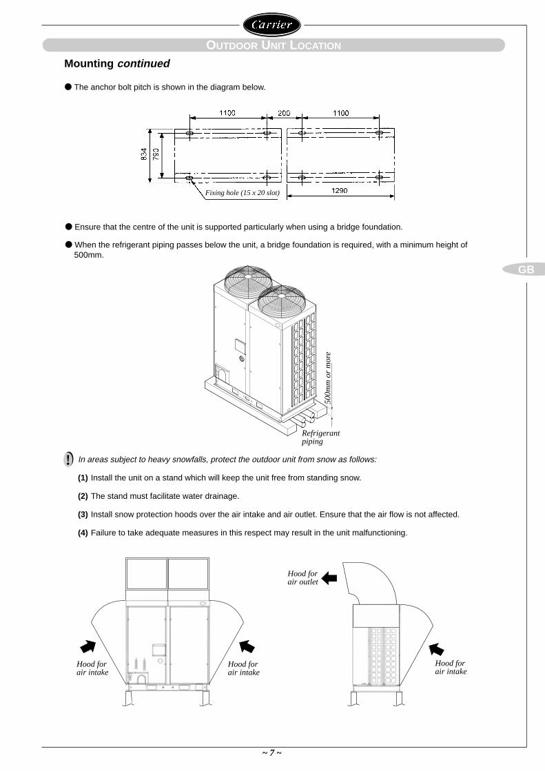
Hood for air intake
Hood for air intake
Hood for air outlet
Hood for air intake
Refrigerantpiping
500m
m o
r m
ore
Fixing hole (15 x 20 slot)
The anchor bolt pitch is shown in the diagram below.
Ensure that the centre of the unit is supported particularly when using a bridge foundation.
When the refrigerant piping passes below the unit, a bridge foundation is required, with a minimum height of500mm.
! In areas subject to heavy snowfalls, protect the outdoor unit from snow as follows:
(1) Install the unit on a stand which will keep the unit free from standing snow.
(2) The stand must facilitate water drainage.
(3) Install snow protection hoods over the air intake and air outlet. Ensure that the air flow is not affected.
(4) Failure to take adequate measures in this respect may result in the unit malfunctioning.
~ 8 ~
GB
GAS FLOW DISTRIBUTOR LOCATION
Electric parts box
Indoor unit connectionside 500mm or more
450mm x 450mm Access panel
Electric parts box
Access panel
Outdoor unitconnectionside 500mmor more
100m
m o
r m
ore
20m
m o
r m
ore
50m
m o
r m
ore
500m
mor
mor
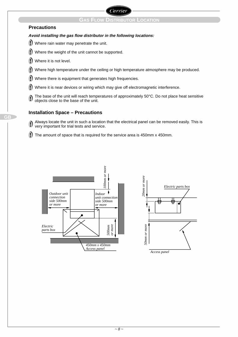
eInstallation Space – Precautions
Avoid installing the gas flow distributor in the following locations:
Where rain water may penetrate the unit.
Where the weight of the unit cannot be supported.
Where it is not level.
Where high temperature under the ceiling or high temperature atmosphere may be produced.
Where there is equipment that generates high frequencies.
Where it is near devices or wiring which may give off electromagnetic interference.
The base of the unit will reach temperatures of approximately 50°C. Do not place heat sensitiveobjects close to the base of the unit.
Precautions
!!!!!!
!
Always locate the unit in such a location that the electrical panel can be removed easily. This isvery important for trial tests and service.
The amount of space that is required for the service area is 450mm x 450mm.
!
!
~ 9 ~
GB
GAS FLOW DISTRIBUTOR LOCATION
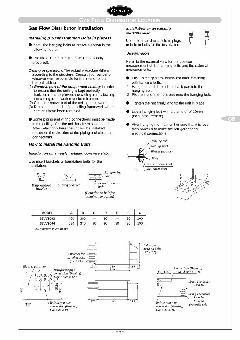
Gas Flow Distributor Installation
Installing ø 10mm Hanging Bolts (4 pieces)
Install the hanging bolts at intervals shown in thefollowing figure.
Use the ø 10mm hanging bolts (to be locallyprocured).
Ceiling preparation: The actual procedure differsaccording to the structure. Consult your builder orwhoever was responsible for the interior of thehouse/building.
(1) Remove part of the suspended ceiling: In orderto ensure that the ceiling is kept perfectlyhorizontal and to prevent the ceiling from vibrating,the ceiling framework must be reinforced.
(2) Cut and remove part of the ceiling framework.(3) Reinforce the ends of the ceiling framework where
sections have been removed.
Some piping and wiring connections must be madein the ceiling after the unit has been suspended.After selecting where the unit will be installeddecide on the direction of the piping and electricalconnections.
How to install the Hanging Bolts
Installation on a newly installed concrete slab:
Use insert brackets or foundation bolts for the installation.
Suspension
Refer to the external view for the positionmeasurement of the hanging bolts and the externalmeasurements.
Pick up the gas flow distributor after matching with hanging bolts.
1 Hang the notch hole of the back part into the hanging bolt.
2 Fix the slot of the front part onto the hanging bolt.
Tighten the nut firmly, and fix the unit in place.
Use a hanging bolt with a diameter of 10mm (local procurement).
After hanging the main unit ensure that it is level then proceed to make the refrigerant and electrical connections.
Installation on an existing concrete slab:
Use hole-in anchors, hole-in plugsor hole-in bolts for the installation.
Knife-shapedbracket
(Foundation bolt forhanging the piping)
Sliding bracket
Hanging bolt
Nut (up side)
Washer (up side)
Body
Washer (down side)
Nut (down side)Reinforcingbar
Foundationbolt 2
1
A
C DE F
90
90 5555
110
300
30080
50
540 170170
Electric parts boxRefrigerant pipeconnection (Brazing)Liquid side ø 12.7
Refrigerant pipeconnection (Brazing)Gas side ø 19
610640
15 15 15B
(12 notches forhanging bolts
(12 x 21)
2 slots forhanging bolts(12 x 52)
Connection (Brazing)Liquid side ø 15.9
Wiring knockouts9 x ø 10
Wiring knockouts4 x ø 161 x ø 20
(opposite side)
G 125
80
MODEL A B C D E F G
38VV9003 460 300 — 90 — 90 100
38VV9004 530 370 90 90 90 90 190
All dimensions are in mm
Refrigerant pipe connection (Brazing)Gas side ø 28.6
Outdoor unit Gas pipe Liquid pipe
38VVH25 19 19 12.7 12.7
28.6 15.9
~ 10 ~
GB
~ 10 ~
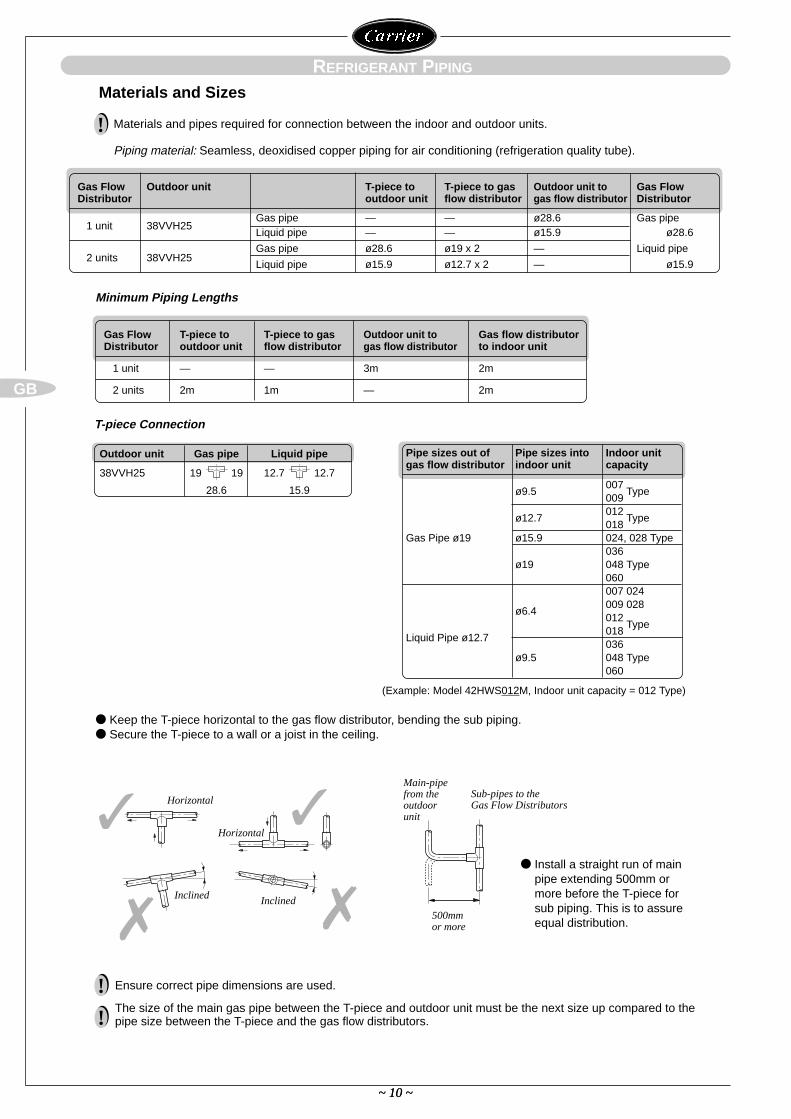
Ensure correct pipe dimensions are used.
The size of the main gas pipe between the T-piece and outdoor unit must be the next size up compared to thepipe size between the T-piece and the gas flow distributors.
!
!
REFRIGERANT PIPING
Materials and Sizes
T-piece Connection
Minimum Piping Lengths
Materials and pipes required for connection between the indoor and outdoor units.
Piping material: Seamless, deoxidised copper piping for air conditioning (refrigeration quality tube).
!
Gas Flow Outdoor unit T-piece to T-piece to gas Outdoor unit to Gas Flow Distributor outdoor unit flow distributor gas flow distributor Distributor
1 unit 38VVH25Gas pipe — — ø28.6 Gas pipeLiquid pipe — — ø15.9 ø28.6
2 units 38VVH25Gas pipe ø28.6 ø19 x 2 — Liquid pipe
Liquid pipe ø15.9 ø12.7 x 2 — ø15.9
Gas Flow T-piece to T-piece to gas Outdoor unit to Gas flow distributor Distributor outdoor unit flow distributor gas flow distributor to indoor unit
1 unit — — 3m 2m
2 units 2m 1m — 2m
(Example: Model 42HWS012M, Indoor unit capacity = 012 Type)
Keep the T-piece horizontal to the gas flow distributor, bending the sub piping. Secure the T-piece to a wall or a joist in the ceiling.
Install a straight run of main pipe extending 500mm ormore before the T-piece forsub piping. This is to assureequal distribution.
Main-pipefrom theoutdoorunit
500mmor more
Sub-pipes to the Gas Flow DistributorsHorizontal
Horizontal
Inclined Inclined
Pipe sizes out of Pipe sizes into Indoor unitgas flow distributor indoor unit capacity
ø9.5007
Type009
ø12.7012
Type018
Gas Pipe ø19 ø15.9 024, 028 Type036
ø19 048 Type060007 024009 028
ø6.4012
Type018
Liquid Pipe ø12.7036
ø9.5 048 Type060
~ 11 ~
GB
REFRIGERANT PIPING
Service Valve
Accessory Pipe
Joint90° Elbow
Joint
Interconnecting Pipe
Interconnecting Pipe
When leading the pipes out from the bottom, pass the pipes through the rubber cover, (knockout holesprovided).
Ensure that the rubber cover is not removed under any circumstances.
Cleanliness is essential; keep the piping securely sealed at all times during the installation.
Do not use a liquid line sight glass, or incorporate an oil trap in vertical pipework.
A drier is included in the integral piping of the outdoor unit.
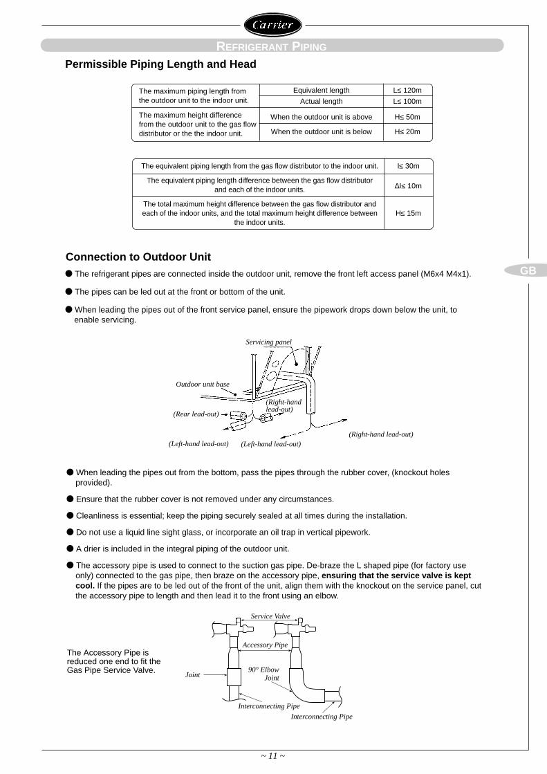
The accessory pipe is used to connect to the suction gas pipe. De-braze the L shaped pipe (for factory useonly) connected to the gas pipe, then braze on the accessory pipe, ensuring that the service valve is keptcool. If the pipes are to be led out of the front of the unit, align them with the knockout on the service panel, cutthe accessory pipe to length and then lead it to the front using an elbow.
The Accessory Pipe isreduced one end to fit theGas Pipe Service Valve.
The refrigerant pipes are connected inside the outdoor unit, remove the front left access panel (M6x4 M4x1).
The pipes can be led out at the front or bottom of the unit.
When leading the pipes out of the front service panel, ensure the pipework drops down below the unit, toenable servicing.
Connection to Outdoor Unit
Servicing panel
(Right-hand lead-out)(Left-hand lead-out)
Outdoor unit base
(Rear lead-out)
(Left-hand lead-out)
(Right-handlead-out)
The equivalent piping length from the gas flow distributor to the indoor unit. I≤ 30m
The equivalent piping length difference between the gas flow distributor∆I≤ 10mand each of the indoor units.
The total maximum height difference between the gas flow distributor and each of the indoor units, and the total maximum height difference between H≤ 15m
the indoor units.
Permissible Piping Length and Head
The maximum piping length from Equivalent length L≤ 120mthe outdoor unit to the indoor unit. Actual length L≤ 100m
The maximum height difference When the outdoor unit is above H≤ 50mfrom the outdoor unit to the gas flow
When the outdoor unit is below H≤ 20mdistributor or the the indoor unit.
~ 12 ~
GB
The system purge must be completed before supplying power to ensure that the gas flow distributors PMVs areopen.
When removing air and dehydrating refrigerant pipework, use an approved type of vacuum pump only; doNOT use the factory charge to purge the air.
Ensure to create a vacuum, at -76 cmHgG (-1.013 x 10⁵ Pa) at both the liquid and gas sides.
~ 12 ~
REFRIGERANT PIPING
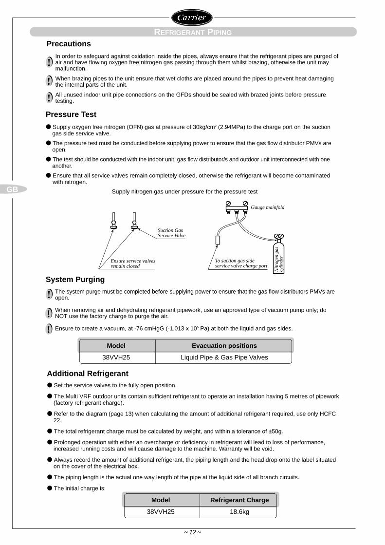
Supply nitrogen gas under pressure for the pressure test
Gauge mainfold
Nit
roge
n ga
scy
lind
erTo suction gas side service valve charge port
Suction GasService Valve
Ensure service valvesremain closed
!
!
!
Supply oxygen free nitrogen (OFN) gas at pressure of 30kg/cm2 (2.94MPa) to the charge port on the suction gas side service valve.
The pressure test must be conducted before supplying power to ensure that the gas flow distributor PMVs areopen.
The test should be conducted with the indoor unit, gas flow distributor/s and outdoor unit interconnected with oneanother.
Ensure that all service valves remain completely closed, otherwise the refrigerant will become contaminated with nitrogen.
Pressure Test
System Purging
Model Evacuation positions
38VVH25 Liquid Pipe & Gas Pipe Valves
Set the service valves to the fully open position.
The Multi VRF outdoor units contain sufficient refrigerant to operate an installation having 5 metres of pipework(factory refrigerant charge).
Refer to the diagram (page 13) when calculating the amount of additional refrigerant required, use only HCFC22.
The total refrigerant charge must be calculated by weight, and within a tolerance of ±50g.
Prolonged operation with either an overcharge or deficiency in refrigerant will lead to loss of performance,increased running costs and will cause damage to the machine. Warranty will be void.
Always record the amount of additional refrigerant, the piping length and the head drop onto the label situatedon the cover of the electrical box.
The piping length is the actual one way length of the pipe at the liquid side of all branch circuits.
The initial charge is:
Additional Refrigerant
Model Refrigerant Charge
38VVH25 18.6kg
Precautions
In order to safeguard against oxidation inside the pipes, always ensure that the refrigerant pipes are purged ofair and have flowing oxygen free nitrogen gas passing through them whilst brazing, otherwise the unit maymalfunction.
When brazing pipes to the unit ensure that wet cloths are placed around the pipes to prevent heat damagingthe internal parts of the unit.
All unused indoor unit pipe connections on the GFDs should be sealed with brazed joints before pressuretesting.
!
!
!
~ 13 ~
GB
~ 13 ~
REFRIGERANT PIPING
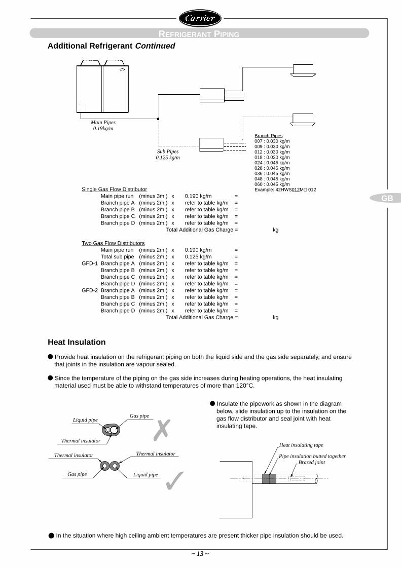
Main Pipes0.19kg/m
Sub Pipes0.125 kg/m
Provide heat insulation on the refrigerant piping on both the liquid side and the gas side separately, and ensurethat joints in the insulation are vapour sealed.
Since the temperature of the piping on the gas side increases during heating operations, the heat insulatingmaterial used must be able to withstand temperatures of more than 120°C.
Additional Refrigerant Continued
Heat Insulation
Single Gas Flow DistributorMain pipe run (minus 3m.) x 0.190 kg/m =Branch pipe A (minus 2m.) x refer to table kg/m =Branch pipe B (minus 2m.) x refer to table kg/m =Branch pipe C (minus 2m.) x refer to table kg/m =Branch pipe D (minus 2m.) x refer to table kg/m =
Total Additional Gas Charge = kg
Two Gas Flow DistributorsMain pipe run (minus 2m.) x 0.190 kg/m =Total sub pipe (minus 2m.) x 0.125 kg/m =
GFD-1 Branch pipe A (minus 2m.) x refer to table kg/m =Branch pipe B (minus 2m.) x refer to table kg/m =Branch pipe C (minus 2m.) x refer to table kg/m =Branch pipe D (minus 2m.) x refer to table kg/m =
GFD-2 Branch pipe A (minus 2m.) x refer to table kg/m =Branch pipe B (minus 2m.) x refer to table kg/m =Branch pipe C (minus 2m.) x refer to table kg/m =Branch pipe D (minus 2m.) x refer to table kg/m =
Total Additional Gas Charge = kg
Insulate the pipework as shown in the diagrambelow, slide insulation up to the insulation on thegas flow distributor and seal joint with heatinsulating tape.
In the situation where high ceiling ambient temperatures are present thicker pipe insulation should be used.
Liquid pipe
Thermal insulator
Thermal insulator
Gas pipe
Gas pipe
Thermal insulator
Liquid pipe
Branch Pipes007 : 0.030 kg/m009 : 0.030 kg/m012 : 0.030 kg/m018 : 0.030 kg/m024 : 0.045 kg/m028 : 0.045 kg/m036 : 0.045 kg/m048 : 0.045 kg/m060 : 0.045 kg/mExample: 42HWS012M⇒ 012
Heat insulating tape
Pipe insulation butted togetherBrazed joint
~ 14 ~
GB
4 4
NEL1 L2 L3
GFD-1 GFD-2
R S T N E
~ 14 ~
ELECTRICAL WIRING
Precautions
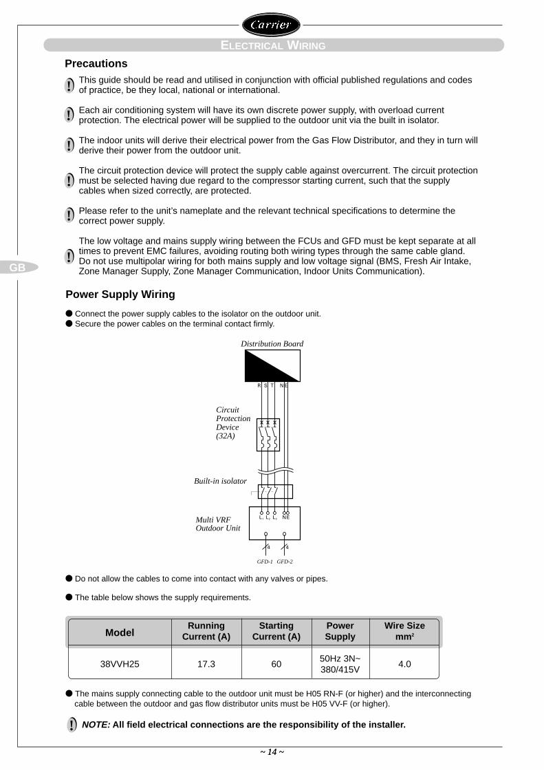
Multi VRFOutdoor Unit
Distribution Board
Connect the power supply cables to the isolator on the outdoor unit. Secure the power cables on the terminal contact firmly.
Do not allow the cables to come into contact with any valves or pipes.
The table below shows the supply requirements.
The mains supply connecting cable to the outdoor unit must be H05 RN-F (or higher) and the interconnectingcable between the outdoor and gas flow distributor units must be H05 VV-F (or higher).
Power Supply Wiring
ModelRunning Starting Power Wire Size
Current (A) Current (A) Supply mm2
50Hz 3N~38VVH25 17.3 60
380/415V4.0
This guide should be read and utilised in conjunction with official published regulations and codesof practice, be they local, national or international.
Each air conditioning system will have its own discrete power supply, with overload currentprotection. The electrical power will be supplied to the outdoor unit via the built in isolator.
The indoor units will derive their electrical power from the Gas Flow Distributor, and they in turn willderive their power from the outdoor unit.
The circuit protection device will protect the supply cable against overcurrent. The circuit protectionmust be selected having due regard to the compressor starting current, such that the supplycables when sized correctly, are protected.
Please refer to the unit’s nameplate and the relevant technical specifications to determine thecorrect power supply.
The low voltage and mains supply wiring between the FCUs and GFD must be kept separate at alltimes to prevent EMC failures, avoiding routing both wiring types through the same cable gland.Do not use multipolar wiring for both mains supply and low voltage signal (BMS, Fresh Air Intake,Zone Manager Supply, Zone Manager Communication, Indoor Units Communication).
!
NOTE: All field electrical connections are the responsibility of the installer.!
!
!
!
!
!
Circuit ProtectionDevice(32A)
Built-in isolator
GFD-1 GFD-2
~ 15 ~
GB
L l
~ 15 ~
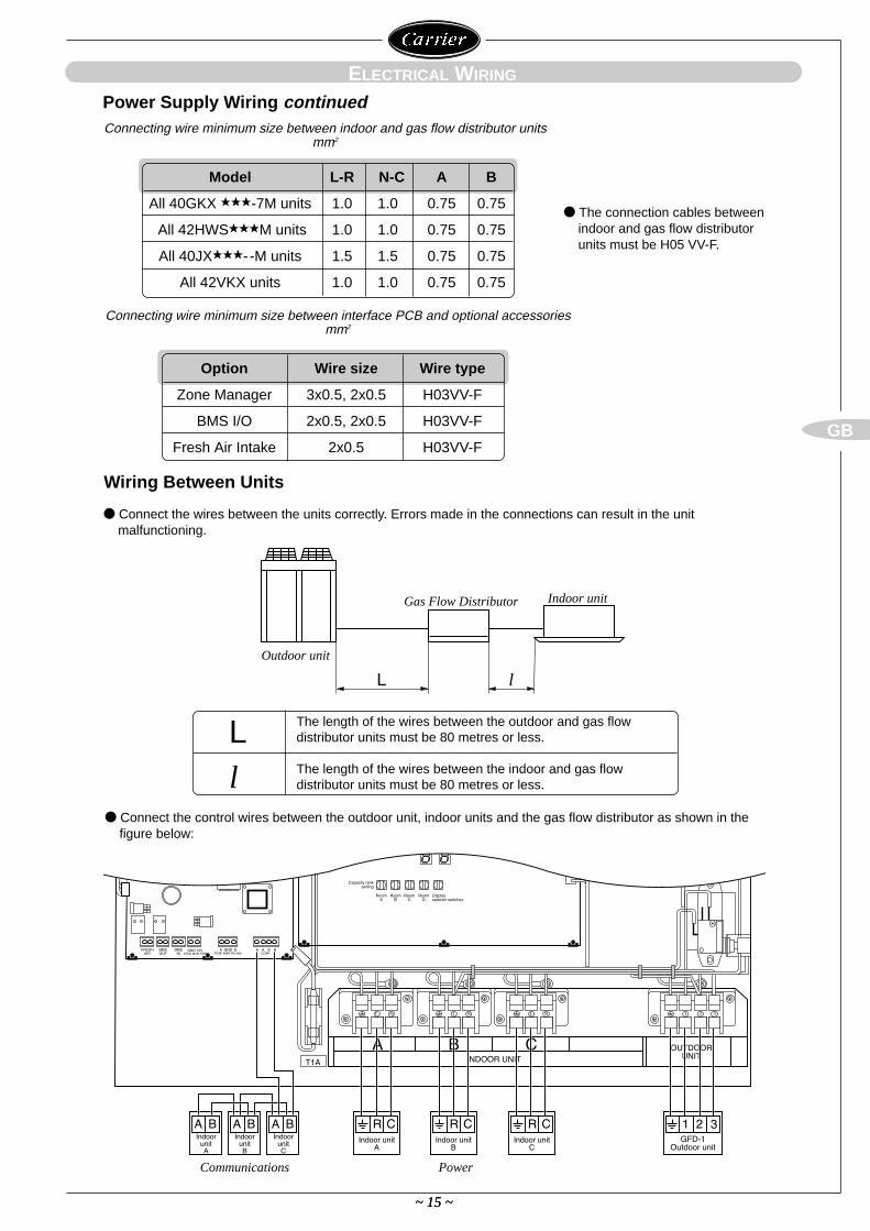
Outdoor unit
Communications Power
Gas Flow Distributor Indoor unit
ELECTRICAL WIRING
Connect the wires between the units correctly. Errors made in the connections can result in the unitmalfunctioning.
The connection cables betweenindoor and gas flow distributorunits must be H05 VV-F.
Connecting wire minimum size between indoor and gas flow distributor units mm2
Connecting wire minimum size between interface PCB and optional accessories mm2
Wiring Between Units
Connect the control wires between the outdoor unit, indoor units and the gas flow distributor as shown in thefigure below:
The length of the wires between the outdoor and gas flowdistributor units must be 80 metres or less.
The length of the wires between the indoor and gas flowdistributor units must be 80 metres or less.
Ll
Power Supply Wiring continued
Model L-R N-C A B
All 40GKX -7M units 1.0 1.0 0.75 0.75
All 42HWSM units 1.0 1.0 0.75 0.75
All 40JX- -M units 1.5 1.5 0.75 0.75
All 42VKX units 1.0 1.0 0.75 0.75
Option Wire size Wire type
Zone Manager 3x0.5, 2x0.5 H03VV-F
BMS I/O 2x0.5, 2x0.5 H03VV-F
Fresh Air Intake 2x0.5 H03VV-F
1 2 3
~ 16 ~
GB
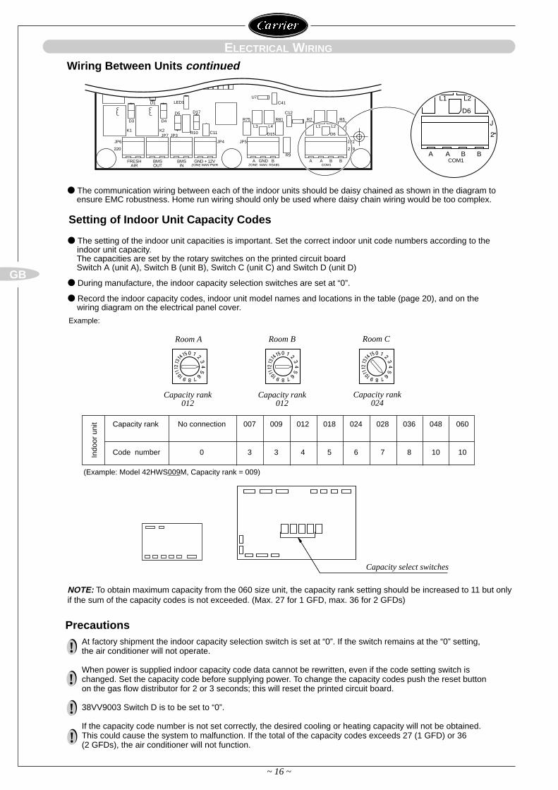
Capacity rank No connection 007 009 012 018 024 028 036 048 060
Code number 0 3 3 4 5 6 7 8 10 10Indo
or u
nit
(Example: Model 42HWS009M, Capacity rank = 009)
Capacity select switches
ELECTRICAL WIRING
Setting of Indoor Unit Capacity Codes
PrecautionsAt factory shipment the indoor capacity selection switch is set at “0”. If the switch remains at the “0” setting,the air conditioner will not operate.
When power is supplied indoor capacity code data cannot be rewritten, even if the code setting switch ischanged. Set the capacity code before supplying power. To change the capacity codes push the reset buttonon the gas flow distributor for 2 or 3 seconds; this will reset the printed circuit board.
38VV9003 Switch D is to be set to “0”.
If the capacity code number is not set correctly, the desired cooling or heating capacity will not be obtained.This could cause the system to malfunction. If the total of the capacity codes exceeds 27 (1 GFD) or 36(2 GFDs), the air conditioner will not function.
!
!
!
!
The setting of the indoor unit capacities is important. Set the correct indoor unit code numbers according to theindoor unit capacity. The capacities are set by the rotary switches on the printed circuit board Switch A (unit A), Switch B (unit B), Switch C (unit C) and Switch D (unit D)
During manufacture, the indoor capacity selection switches are set at “0”.
Record the indoor capacity codes, indoor unit model names and locations in the table (page 20), and on thewiring diagram on the electrical panel cover.
Example:
Room A
Capacity rank012
Capacity rank012
Capacity rank024
Room B Room C
FRESHAIR
BMSOUT
BMSIN
GND + 12VZONE MAN PWR
D3 D4
D5
D1
K1 K2
LED1
D17
C11R10JP7 JP3
JP6 JP4
220
D15
L3 L4
JP5
R75 R81 R2 R5
L1 L2
D6
C12
C41U7
R9
JP2
ZONE MAN RS485A GND B
COM1A A B B
219
L1 L2
D6
COM1A A B B
Wiring Between Units continued
The communication wiring between each of the indoor units should be daisy chained as shown in the diagram toensure EMC robustness. Home run wiring should only be used where daisy chain wiring would be too complex.
NOTE: To obtain maximum capacity from the 060 size unit, the capacity rank setting should be increased to 11 but onlyif the sum of the capacity codes is not exceeded. (Max. 27 for 1 GFD, max. 36 for 2 GFDs)
~ 17 ~
GB
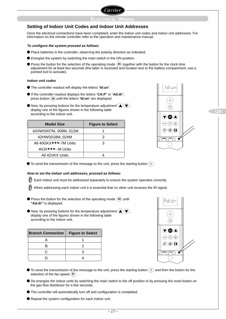
Setting of Indoor Unit Codes and Indoor Unit Addresses
ELECTRICAL WIRING
Once the electrical connections have been completed, enter the indoor unit codes and indoor unit addresses. Forinformation on the remote controller refer to the operation and maintenance manual.
To configure the system proceed as follows:
Place batteries in the controller, observing the polarity direction as indicated.
Energise the system by switching the main switch in the ON position.
Press the button for the selection of the operating mode together with the button for the clock timeadjustment for at least two seconds (the latter is recessed and located next to the battery compartment, use apointed tool to activate).
Indoor unit codes
The controller readout will display the letters “Id:un”.
If the controller readout displays the letters “CA:P” or “Ad:dr”,press button until the letters “Id:un” are displayed.
Now, by pressing buttons for the temperature adjustment ,display one of the figures shown in the following tableaccording to the indoor unit.
M
To send the transmission of the message to the unit, press the starting button .I
M
Branch Connection Figure to Select
A 1
B 2
C 3
D 4
Press the button for the selection of the operating mode until“Ad:dr” is displayed.
Now, by pressing buttons for the temperature adjustment ,display one of the figures shown in the following tableaccording to the indoor unit.
M
To send the transmission of the message to the unit, press the starting button and then the button for theselection of the fan speed .
De-energise the indoor units by switching the main switch to the off position or by pressing the reset button onthe gas flow distributor for a few seconds.
The controller will automatically turn off and configuration is completed.
Repeat the system configuration for each indoor unit.
I
Model Size Figure to Select
42HWS007M, 009M, 012M 1
42HWS018M, 024M 2
All 40GKX-7M Units 3
40JX- -M Units
All 42VKX Units 4
Each indoor unit must be addressed separately to ensure the system operates correctly.
When addressing each indoor unit it is essential that no other unit receives the IR signal.
!!
Now to set the Indoor unit addresses, proceed as follows:
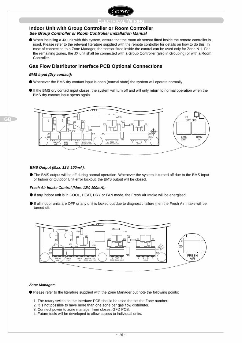
Zone Manager:
Please refer to the literature supplied with the Zone Manager but note the following points:
1. The rotary switch on the Interface PCB should be used the set the Zone number.2. It is not possible to have more than one zone per gas flow distributor.3. Connect power to zone manager from closest GFD PCB.4. Future tools will be developed to allow access to individual units.
~ 18 ~
GB
BMS Input (Dry contact):
Whenever the BMS dry contact input is open (normal state) the system will operate normally.
If the BMS dry contact input closes, the system will turn off and will only return to normal operation when theBMS dry contact input opens again.
When installing a JX unit with this system, ensure that the room air sensor fitted inside the remote controller isused. Please refer to the relevant literature supplied with the remote controller for details on how to do this. Incase of connection to a Zone Manager, the sensor fitted inside the control can be used only for Zone N.1. Forthe remaining zones, the JX unit shall be connected with a Group Controller (also in Grouping) or with a RoomController.
Gas Flow Distributor Interface PCB Optional Connections
Indoor Unit with Group Controller or Room ControllerSee Group Controller or Room Controller Installation Manual
BMS Output (Max. 12V, 100mA):
The BMS output will be off during normal operation. Whenever the system is turned off due to the BMS Inputor Indoor or Outdoor Unit error lockout, the BMS output will be closed.
Fresh Air Intake Control (Max. 12V, 100mA):
If any indoor unit is in COOL, HEAT, DRY or FAN mode, the Fresh Air Intake will be energised.
If all indoor units are OFF or any unit is locked out due to diagnostic failure then the Fresh Air Intake will be turned off.
ELECTRICAL WIRING
FRESHAIR
BMSOUT
BMSIN
GND + 12VZONE MAN PWR
D3 D4
D5
D1
K1 K2
LED1
D17
C11R10JP7 JP3
JP6 JP4
220
D15
L3 L4
JP5
R75 R81 R2 R5
L1 L2
D6
C12
C41U7
R9
JP2
ZONE MAN RS485A GND B
COM1A A B B
219 BMSOUT
BMSIN
K2JP7 JP3
FRESHAIR
BMSOUT
BMSIN
GND + 12VZONE MAN PWR
D3 D4
D5
D1
K1 K2
LED1
D17
C11R10JP7 JP3
JP6 JP4
220
D15
L3 L4
JP5
R75 R81 R2 R5
L1 L2
D6
C12
C41U7
R9
JP2
ZONE MAN RS485A GND B
COM1A A B B
219
FRESHAIR
~ 19 ~
GB
ELECTRICAL WIRING
TRIAL RUN
Precautions
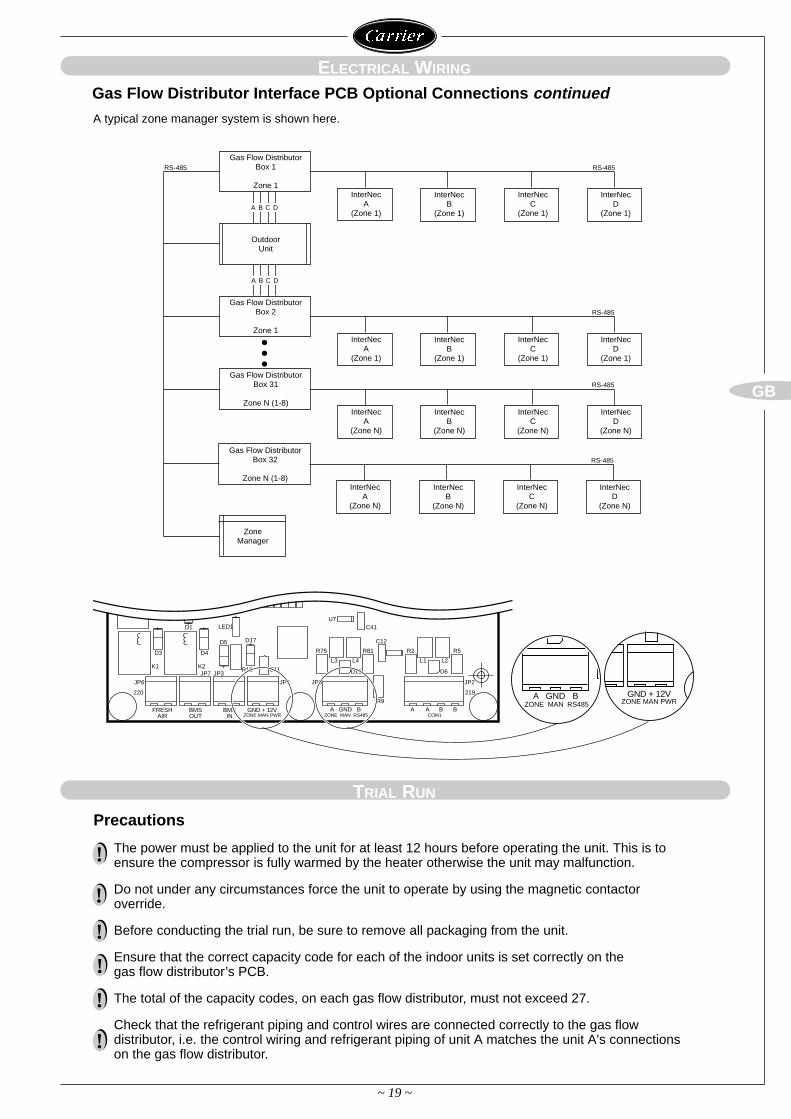
The power must be applied to the unit for at least 12 hours before operating the unit. This is toensure the compressor is fully warmed by the heater otherwise the unit may malfunction.
Do not under any circumstances force the unit to operate by using the magnetic contactoroverride.
Before conducting the trial run, be sure to remove all packaging from the unit.
Ensure that the correct capacity code for each of the indoor units is set correctly on the gas flow distributor’s PCB.
The total of the capacity codes, on each gas flow distributor, must not exceed 27.
Check that the refrigerant piping and control wires are connected correctly to the gas flowdistributor, i.e. the control wiring and refrigerant piping of unit A matches the unit A's connectionson the gas flow distributor.
!
!
!
!
!
!
Gas Flow Distributor Interface PCB Optional Connections continued
Gas Flow DistributorBox 1
Zone 1
Outdoor Unit
Gas Flow DistributorBox 2
Zone 1
Gas Flow DistributorBox 31
Zone N (1-8)
Gas Flow DistributorBox 32
Zone N (1-8)
ZoneManager
InterNecA
(Zone 1)
InterNecB
(Zone 1)
InterNecC
(Zone 1)
InterNecD
(Zone 1)
InterNecA
(Zone 1)
InterNecB
(Zone 1)
InterNecC
(Zone 1)
InterNecD
(Zone 1)
InterNecA
(Zone N)
InterNecB
(Zone N)
InterNecC
(Zone N)
InterNecD
(Zone N)
InterNecA
(Zone N)
InterNecB
(Zone N)
InterNecC
(Zone N)
InterNecD
(Zone N)
A B C D
A B C D
RS-485 RS-485
RS-485
RS-485
RS-485
A typical zone manager system is shown here.
FRESHAIR
BMSOUT
BMSIN
GND + 12VZONE MAN PWR
D3 D4
D5
D1
K1 K2
LED1
D17
C11R10JP7 JP3
JP6 JP4
220
D15
L3 L4
JP5
R75 R81 R2 R5
L1 L2
D6
C12
C41U7
R9
JP2
ZONE MAN RS485A GND B
COM1A A B B
219 GND + 12VZONE MAN PWRZONE MAN RS485
A GND B
~ 20 ~
GB
~ 20 ~
TRIAL RUN
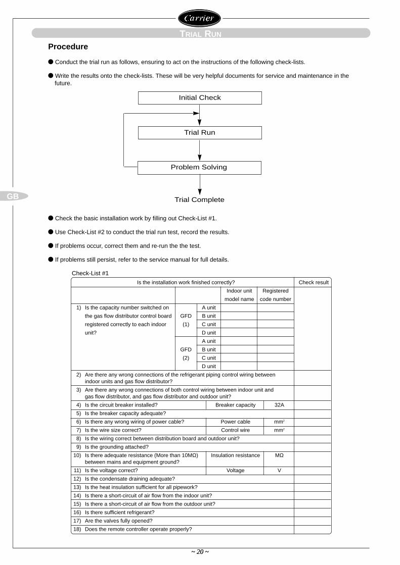
Conduct the trial run as follows, ensuring to act on the instructions of the following check-lists.
Write the results onto the check-lists. These will be very helpful documents for service and maintenance in thefuture.
Check the basic installation work by filling out Check-List #1.
Use Check-List #2 to conduct the trial run test, record the results.
If problems occur, correct them and re-run the the test.
If problems still persist, refer to the service manual for full details.
Procedure
Initial Check
Trial Run
Problem Solving
Trial Complete
Is the installation work finished correctly? Check result
Indoor unit Registered
model name code number
1) Is the capacity number switched on A unit
the gas flow distributor control board GFD B unit
registered correctly to each indoor (1) C unit
unit? D unit
A unit
GFD B unit
(2) C unit
D unit
2) Are there any wrong connections of the refrigerant piping control wiring betweenindoor units and gas flow distributor?
3) Are there any wrong connections of both control wiring between indoor unit andgas flow distributor, and gas flow distributor and outdoor unit?
4) Is the circuit breaker installed? Breaker capacity 32A
5) Is the breaker capacity adequate?
6) Is there any wrong wiring of power cable? Power cable mm2
7) Is the wire size correct? Control wire mm2
8) Is the wiring correct between distribution board and outdoor unit?
9) Is the grounding attached?
10) Is there adequate resistance (More than 10MΩ) Insulation resistance MΩbetween mains and equipment ground?
11) Is the voltage correct? Voltage V
12) Is the condensate draining adequate?
13) Is the heat insulation sufficient for all pipework?
14) Is there a short-circuit of air flow from the indoor unit?
15) Is there a short-circuit of air flow from the outdoor unit?
16) Is there sufficient refrigerant?
17) Are the valves fully opened?
18) Does the remote controller operate properly?
Check-List #1
~ 21 ~
GB
~ 21 ~
TRIAL RUN
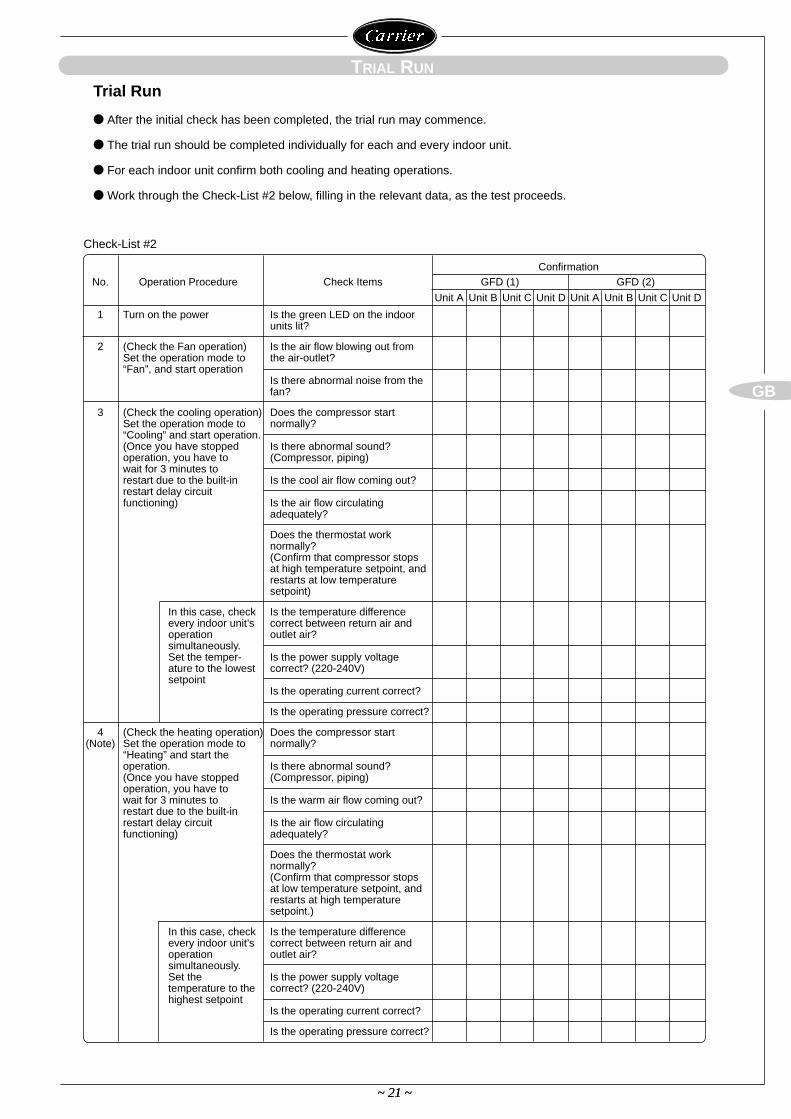
After the initial check has been completed, the trial run may commence.
The trial run should be completed individually for each and every indoor unit.
For each indoor unit confirm both cooling and heating operations.
Work through the Check-List #2 below, filling in the relevant data, as the test proceeds.
Trial Run
Check-List #2
ConfirmationNo. Operation Procedure Check Items GFD (1) GFD (2)
Unit A Unit B Unit C Unit D Unit A Unit B Unit C Unit D
1 Turn on the power Is the green LED on the indoor units lit?
2 (Check the Fan operation) Is the air flow blowing out fromSet the operation mode to the air-outlet?“Fan”, and start operation
Is there abnormal noise from thefan?
3 (Check the cooling operation) Does the compressor startSet the operation mode to normally?“Cooling” and start operation.(Once you have stopped Is there abnormal sound?operation, you have to (Compressor, piping)wait for 3 minutes torestart due to the built-in Is the cool air flow coming out?restart delay circuitfunctioning) Is the air flow circulating
adequately?
Does the thermostat worknormally?(Confirm that compressor stopsat high temperature setpoint, andrestarts at low temperature setpoint)
In this case, check Is the temperature difference every indoor unit’s correct between return air andoperation outlet air?simultaneously.Set the temper- Is the power supply voltageature to the lowest correct? (220-240V)setpoint
Is the operating current correct?
Is the operating pressure correct?
4 (Check the heating operation) Does the compressor start(Note) Set the operation mode to normally?
“Heating” and start theoperation. Is there abnormal sound?(Once you have stopped (Compressor, piping)operation, you have towait for 3 minutes to Is the warm air flow coming out?restart due to the built-inrestart delay circuit Is the air flow circulatingfunctioning) adequately?
Does the thermostat worknormally?(Confirm that compressor stopsat low temperature setpoint, andrestarts at high temperaturesetpoint.)
In this case, check Is the temperature differenceevery indoor unit’s correct between return air andoperation outlet air?simultaneously.Set the Is the power supply voltagetemperature to the correct? (220-240V)highest setpoint
Is the operating current correct?
Is the operating pressure correct?
~ 22 ~
GB
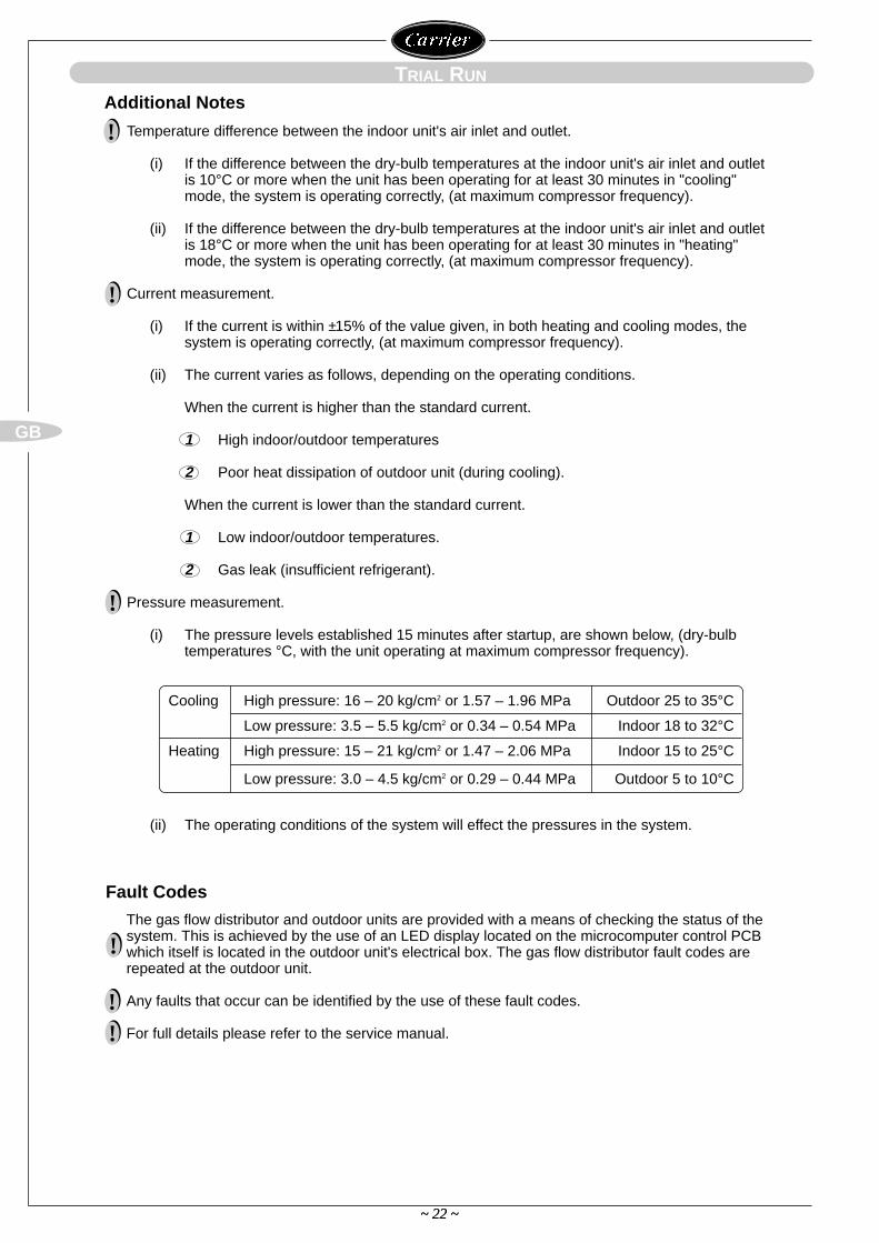
Temperature difference between the indoor unit's air inlet and outlet.
(i) If the difference between the dry-bulb temperatures at the indoor unit's air inlet and outlet is 10°C or more when the unit has been operating for at least 30 minutes in "cooling" mode, the system is operating correctly, (at maximum compressor frequency).
(ii) If the difference between the dry-bulb temperatures at the indoor unit's air inlet and outlet is 18°C or more when the unit has been operating for at least 30 minutes in "heating" mode, the system is operating correctly, (at maximum compressor frequency).
Current measurement.
(i) If the current is within ±15% of the value given, in both heating and cooling modes, the system is operating correctly, (at maximum compressor frequency).
(ii) The current varies as follows, depending on the operating conditions.
When the current is higher than the standard current.
1 High indoor/outdoor temperatures
2 Poor heat dissipation of outdoor unit (during cooling).
When the current is lower than the standard current.
1 Low indoor/outdoor temperatures.
2 Gas leak (insufficient refrigerant).
Pressure measurement.
(i) The pressure levels established 15 minutes after startup, are shown below, (dry-bulb temperatures °C, with the unit operating at maximum compressor frequency).
The gas flow distributor and outdoor units are provided with a means of checking the status of thesystem. This is achieved by the use of an LED display located on the microcomputer control PCBwhich itself is located in the outdoor unit's electrical box. The gas flow distributor fault codes arerepeated at the outdoor unit.
Any faults that occur can be identified by the use of these fault codes.
For full details please refer to the service manual.
~ 22 ~
TRIAL RUN
Additional Notes
Fault Codes
!
!
!
!
!!
(ii) The operating conditions of the system will effect the pressures in the system.
Cooling High pressure: 16 – 20 kg/cm2 or 1.57 – 1.96 MPa Outdoor 25 to 35°C
Low pressure: 3.5 – 5.5 kg/cm2 or 0.34 – 0.54 MPa Indoor 18 to 32°C
Heating High pressure: 15 – 21 kg/cm2 or 1.47 – 2.06 MPa Indoor 15 to 25°C
Low pressure: 3.0 – 4.5 kg/cm2 or 0.29 – 0.44 MPa Outdoor 5 to 10°C
~ 23 ~
GB
~ 23 ~
TRIAL RUN
Phase Rotation Test Procedure
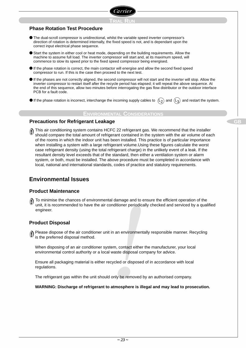
The dual-scroll compressor is unidirectional, whilst the variable speed inverter compressor's direction of rotation is determined internally, the fixed speed is not, and is dependant upon the correct input electrical phase sequence.
Start the system in either cool or heat mode, depending on the building requirements. Allow the machine to assume full load. The inverter compressor will start and, at its maximum speed, will commence to slow its speed prior to the fixed speed compressor being energised.
If the phase rotation is correct, the main contactor will energise and allow the second fixed speed compressor to run. If this is the case then proceed to the next test.
If the phases are not correctly aligned, the second compressor will not start and the inverter will stop. Allow theinverter compressor to restart itself after the recycle period has elapsed; it will repeat the above sequence. Atthe end of this sequence, allow two minutes before interrogating the gas flow distributor or the outdoor interfacePCB for a fault code.
If the phase rotation is incorrect, interchange the incoming supply cables to L2 and L3 and restart the system.
!
ENVIRONMENTAL CONSIDERATIONS
Precautions for Refrigerant Leakage
Product Maintenance
Product Disposal
Environmental Issues
This air conditioning system contains HCFC 22 refrigerant gas. We recommend that the installershould compare the total amount of refrigerant contained in the system with the air volume of eachof the rooms in which the indoor unit has been installed. This practice is of particular importancewhen installing a system with a large refrigerant volume.Using these figures calculate the worstcase refrigerant density (using the total refrigerant charge) in the unlikely event of a leak. If theresultant density level exceeds that of the standard, then either a ventilation system or alarmsystem, or both, must be installed. The above procedure must be completed in accordance withlocal, national and international standards, codes of practice and statutory requirements.
!
To minimise the chances of environmental damage and to ensure the efficient operation of theunit, it is recommended to have the air conditioner periodically checked and serviced by a qualifiedengineer.
Please dispose of the air conditioner unit in an environmentally responsible manner. Recyclingis the preferred disposal method.
When disposing of an air conditioner system, contact either the manufacturer, your localenvironmental control authority or a local waste disposal company for advice.
Ensure all packaging material is either recycled or disposed of in accordance with localregulations.
The refrigerant gas within the unit should only be removed by an authorised company.
WARNING: Discharge of refrigerant to atmosphere is illegal and may lead to prosecution.
!
!