
Oil Refining and Gas Toil refining and gas technology
60
0 University of Technology Department of Chemical Engineering Oil & Gas Technology Lectures 4th year / Unit Operation Branch By Dr. Neran K. Ibrahim
-
Upload
mosteanu-marian -
Category
Documents
-
view
42 -
download
1
description
oil refining and gas technology
Transcript of Oil Refining and Gas Toil refining and gas technology

0
University of Technology Department of Chemical Engineering
Oil & Gas Technology Lectures
4th year / Unit Operation Branch By
Dr. Neran K. Ibrahim

1
Lecture 1 Introduction
Petroleum (Latin Petroleum derived from Greek πέτρα (Latin petra) - rock + έλαιον (Latin oleum) - oil) or crude oil is a naturally occurring liquid found in formations in the Earth consisting of a complex mixture of hydrocarbons (mostly alkanes) of various lengths. The approximate length range is C5H12 to C18H38. Any shorter hydrocarbons are considered natural gas or natural gas liquids, while long-chain hydrocarbons are more viscous, and the longest chains are paraffin wax. In its naturally occurring form, it may contain other nonmetallic elements such as sulfur, oxygen, and nitrogen. It is usually black or dark brown (although it may be yellowish or even greenish) but varies greatly in appearance, depending on its composition. Crude oil may also be found in semi-solid form mixed with sand, as in the Athabasca oil sands in Canada, where it may be referred to as crude bitumen.
Petroleum is used mostly, by volume, for producing fuel oil and gasoline (petrol), both important "primary energy" sources. 84% by volume of the hydrocarbons present in petroleum is converted into energy-rich fuels (petroleum-based fuels), including gasoline, diesel, jet, heating, and other fuel oils, and liquefied petroleum gas.
Due to its
high energy density easy transportability relative abundance
it has become the world's most important source of energy since the mid-1950s. Petroleum is also the raw material for many chemical products, including pharmaceuticals, solvents, fertilizers, pesticides, and plastics; the 16% not used for energy production is converted into these other materials.
Petroleum is found in porous rock formations in the upper strata of some areas of the Earth's crust. There is also petroleum in oil sands (tar sands). Known reserves of petroleum are typically estimated at around 1.2 trillion barrels without oil sands, or 3.74 trillion barrels with oil sands . However, oil production from oil sands is currently severely limited. Consumption is currently around 84 million barrels per day, or 3.6 trillion liters per year. Because of reservoir engineering difficulties, recoverable oil

2
reserves are significantly less than total oil-in-place. At current consumption levels, and assuming that oil will be consumed only from reservoirs, known reserves would be gone around 2039, potentially leading to a global energy crisis. However, this ignores any new discoveries, rapidly increasing consumption in China & India, using oil sands, using synthetic petroleum, and other factors which may extend or reduce this estimate.
Formation Formation of petroleum occurs in a variety of mostly endothermic reactions in high temperature and/or pressure. For example, a kerogen may break down into hydrocarbons of different lengths.
Geologists view crude oil and natural gas as the product of compression and heating of ancient organic materials (i.e. kerogen) over geological time. Formation of petroleum occurs from hydrocarbon pyrolysis, in a variety of mostly endothermic reactions at high temperature and/or pressure. Today's oil formed from the preserved remains of prehistoric zooplankton and algae, which had settled to a sea or lake bottom in large quantities under anoxic conditions. Over geological time the organic matter mixed with mud, and was buried under heavy layers of sediment resulting in high levels of heat and pressure. This caused the organic matter to chemically change, first into a waxy material known as kerogen which is found in various oil shales around the world, and then with more heat into liquid and gaseous hydrocarbons in a process known as catagenesis.
Geologists often refer to the temperature range in which oil forms as an "oil window"—below the minimum temperature oil remains trapped in the form of kerogen, and above the maximum temperature the oil is converted to natural gas through the process of thermal cracking. Although this temperature range is found at different depths below the surface throughout the world, a typical depth for the oil window is 4–6 km. Sometimes, oil which is formed at extreme depths may migrate and become trapped at much shallower depths than where it was formed.
Oil forms at temperatures between about 50°C (120°F) and 175°C (350°F). At higher temperatures, gas is formed and any oil that has already been produced starts to turn into lighter oils and eventually into Methane gas, the lightest and simplest hydrocarbon. At temperatures above about 260°C (500°F), plant and animal remains turn completely to carbon and no more oil or gas are produced.

3
Crude oil reservoirs
Three conditions must be present for oil reservoirs to form:
1. A source rock rich in hydrocarbon material buried deep enough for subterranean heat to cook it into oil.
2. A porous and permeable reservoir rock for it to accumulate in. 3. A cap rock (seal) or other mechanism that prevents it from
escaping to the surface.
Within these reservoirs, fluids will typically organize themselves like a three-layer cake with a layer of water below the oil layer and a layer of gas above it, although the different layers vary in size between reservoirs.
Because most hydrocarbons are lighter than rock or water, they often migrate upward through adjacent rock layers until either reaching the surface or becoming trapped within porous rocks (known as reservoirs) by impermeable rocks above. However, the process is influenced by underground water flows, causing oil to migrate hundreds of kilometers horizontally or even short distances downward before becoming trapped in a reservoir. When hydrocarbons are concentrated in a trap, an oil field forms, from which the liquid can be extracted by drilling and pumping.
The reactions that produce oil and natural gas are often modeled as first order breakdown reactions, where hydrocarbons are broken down to oil and natural gas by a set of parallel reactions, and oil eventually breaks down to natural gas by another set of reactions. The latter set is regularly used in petrochemical plants and oil refineries.

4
Non-conventional oil reservoirs
Oil-eating bacteria biodegrades oil that has escaped to the surface. Oil sands are reservoirs of partially biodegraded oil still in the process of escaping and being biodegraded, but they contain so much migrating oil that, although most of it has escaped, vast amounts are still present—more than can be found in conventional oil reservoirs. The lighter fractions of the crude oil are destroyed first, resulting in reservoirs containing an extremely heavy form of crude oil, called crude bitumen in Canada, or extra-heavy crude oil in Venezuela. These two countries have the world's largest deposits of oil sands.
On the other hand, oil shales are source rocks that have not been exposed to heat or pressure long enough to convert their trapped hydrocarbons into crude oil. Technically speaking, oil shales are not really shales and do not really contain oil, but are usually relatively hard rocks called marls containing a waxy substance called kerogen. The kerogen trapped in the rock can be converted into crude oil using heat and pressure to simulate natural processes. The method has been known for centuries and was patented in 1694 under British Crown Patent No. 330 covering, "A way to extract and make great quantities of pitch, tar, and oil out of a sort of stone." Although oil shales are found in many countries, the United States has the world's largest deposits.
Abiogenic origin
Abiogenic petroleum origin is an alternative hypothesis to the prevailing biological origin theory of petroleum origins. Most popular in Russia and Ukraine between the 1950s and 1980s, the abiogenic hypothesis now has little support amongst contemporary petroleum geologists, who argue that abiogenic petroleum does not exist in significant amounts, and that there is no indication that an application of the hypothesis is or has ever been of commercial value.
The abiogenic hypothesis argues that natural petroleum was formed from deep carbon deposits, perhaps dating to the formation of the Earth; the presence of methane on Saturn's moon Titan is cited as supporting evidence. Supporters of the abiogenic hypothesis suggest that there may be a great deal more petroleum on Earth than commonly thought, and that petroleum may originate from carbon-bearing fluids which migrate upward from the mantle.

5
Although the abiogenic hypothesis was accepted by some geologists in the former Soviet Union, most geologists now consider the biogenic formation of petroleum scientifically supported. Though evidence exists for abiogenic creation of methane and hydrocarbon gases within the Earth, studies indicate they are not produced in commercially significant quantities.
Composition
The proportion of hydrocarbons in the mixture is highly variable and ranges from as much as 97% by weight in the lighter oils to as little as 50% in the heavier oils and bitumens.
The hydrocarbons in crude oil are mostly alkanes, cycloalkanes and various aromatic hydrocarbons while the other organic compounds contain nitrogen, oxygen and sulfur, and trace amounts of metals such as iron, nickel, copper and vanadium. The exact molecular composition varies widely from formation to formation but the proportion of chemical elements vary over fairly narrow limits as follows:
Composition by weight
Element Percent range
Carbon 83 to 87%
Hydrogen 10 to 14%
Nitrogen 0.1 to 2%
Oxygen 0.1 to 1.5%
Sulfur 0.5 to 6%
Metals less than 1000 ppm
Crude oil varies greatly in appearance depending on its composition. It is usually black or dark brown (although it may be yellowish or even
6
greenish). In the reservoir it is usually found in association with natural gas, which being lighter forms a gas cap over the petroleum, and saline water which, being heavier than most forms of crude oil, generally sinks beneath it.
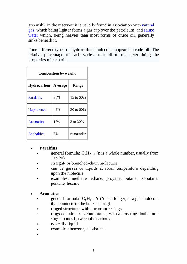
Four different types of hydrocarbon molecules appear in crude oil. The relative percentage of each varies from oil to oil, determining the properties of each oil.
Composition by weight
Hydrocarbon Average Range
Paraffins 30% 15 to 60%
Naphthenes 49% 30 to 60%
Aromatics 15% 3 to 30%
Asphaltics 6% remainder
• Paraffins
general formula: CnH2n+2 (n is a whole number, usually from 1 to 20)
straight- or branched-chain molecules can be gasses or liquids at room temperature depending
upon the molecule examples: methane, ethane, propane, butane, isobutane,
pentane, hexane
• Aromatics general formula: C6H5 - Y (Y is a longer, straight molecule
that connects to the benzene ring) ringed structures with one or more rings rings contain six carbon atoms, with alternating double and
single bonds between the carbons typically liquids examples: benzene, napthalene

7
• Napthenes or Cycloalkanes general formula: CnH2n (n is a whole number usually from 1
to 20) ringed structures with one or more rings rings contain only single bonds between the carbon atoms typically liquids at room temperature examples: cyclohexane, methyl cyclopentane
• Other hydrocarbons
Alkenes • general formula: CnH2n (n is a whole number, usually from
1 to 20) • linear or branched chain molecules containing one carbon-
carbon double-bond • can be liquid or gas • examples: ethylene, butene, isobutene
Dienes and Alkynes • general formula: CnH2n-2 (n is a whole number, usually from
1 to 20) • linear or branched chain molecules containing two carbon-
carbon double-bonds • can be liquid or gas • examples: acetylene, butadienes
There are two things that make hydrocarbons exciting to chemists
• Hydrocarbons contain a lot of energy. Many of the things
derived from crude oil like gasoline, diesel fuel, paraffin wax and so on take advantage of this energy.
• Hydrocarbons can take on many different forms. The smallest hydrocarbon is methane (CH4), which is a gas that is a lighter than air. Longer chains with 5 or more carbons are liquids. Very long chains are solids like wax or tar. By chemically cross-linking hydrocarbon chains you can get everything from synthetic rubber to nylon to the plastic in tupperware. Hydrocarbon chains are very versatile!
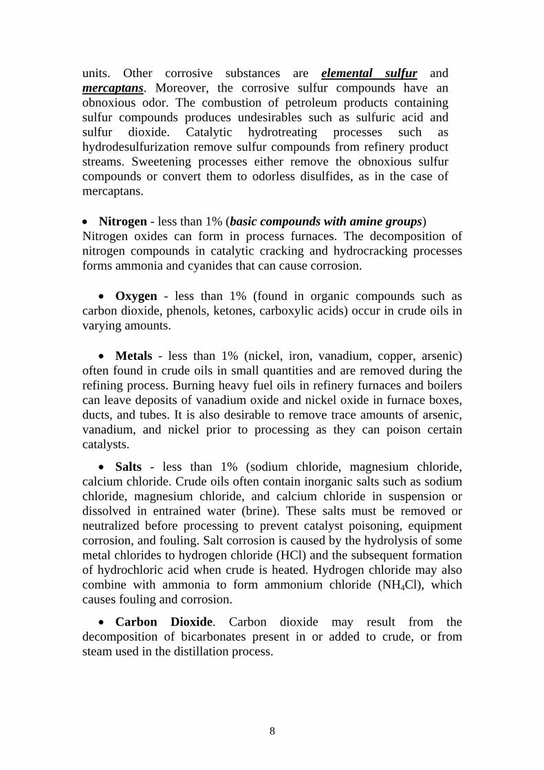
• Sulfur – (hydrogen sulfide, sulfides, disulfides, elemental
sulfur). Each crude oil has different amounts and types of sulfur compounds, but as a rule the proportion, stability, and complexity of the compounds are greater in heavier crude-oil fractions. Hydrogen sulfide is a primary contributor to corrosion in refinery processing
8
units. Other corrosive substances are elemental sulfur and mercaptans. Moreover, the corrosive sulfur compounds have an obnoxious odor. The combustion of petroleum products containing sulfur compounds produces undesirables such as sulfuric acid and sulfur dioxide. Catalytic hydrotreating processes such as hydrodesulfurization remove sulfur compounds from refinery product streams. Sweetening processes either remove the obnoxious sulfur compounds or convert them to odorless disulfides, as in the case of mercaptans. • Nitrogen - less than 1% (basic compounds with amine groups) Nitrogen oxides can form in process furnaces. The decomposition of nitrogen compounds in catalytic cracking and hydrocracking processes forms ammonia and cyanides that can cause corrosion.
• Oxygen - less than 1% (found in organic compounds such as carbon dioxide, phenols, ketones, carboxylic acids) occur in crude oils in varying amounts.
• Metals - less than 1% (nickel, iron, vanadium, copper, arsenic) often found in crude oils in small quantities and are removed during the refining process. Burning heavy fuel oils in refinery furnaces and boilers can leave deposits of vanadium oxide and nickel oxide in furnace boxes, ducts, and tubes. It is also desirable to remove trace amounts of arsenic, vanadium, and nickel prior to processing as they can poison certain catalysts.
• Salts - less than 1% (sodium chloride, magnesium chloride, calcium chloride. Crude oils often contain inorganic salts such as sodium chloride, magnesium chloride, and calcium chloride in suspension or dissolved in entrained water (brine). These salts must be removed or neutralized before processing to prevent catalyst poisoning, equipment corrosion, and fouling. Salt corrosion is caused by the hydrolysis of some metal chlorides to hydrogen chloride (HCl) and the subsequent formation of hydrochloric acid when crude is heated. Hydrogen chloride may also combine with ammonia to form ammonium chloride (NH4Cl), which causes fouling and corrosion.
• Carbon Dioxide. Carbon dioxide may result from the decomposition of bicarbonates present in or added to crude, or from steam used in the distillation process.
9
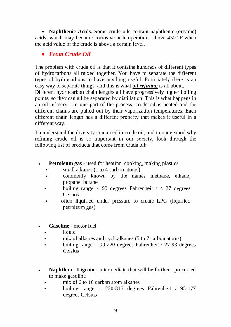
• Naphthenic Acids. Some crude oils contain naphthenic (organic) acids, which may become corrosive at temperatures above 450° F when the acid value of the crude is above a certain level.
• From Crude Oil The problem with crude oil is that it contains hundreds of different types of hydrocarbons all mixed together. You have to separate the different types of hydrocarbons to have anything useful. Fortunately there is an easy way to separate things, and this is what oil refining is all about. Different hydrocarbon chain lengths all have progressively higher boiling points, so they can all be separated by distillation. This is what happens in an oil refinery - in one part of the process, crude oil is heated and the different chains are pulled out by their vaporization temperatures. Each different chain length has a different property that makes it useful in a different way.
To understand the diversity contained in crude oil, and to understand why refining crude oil is so important in our society, look through the following list of products that come from crude oil:
• Petroleum gas - used for heating, cooking, making plastics small alkanes (1 to 4 carbon atoms) commonly known by the names methane, ethane,
propane, butane boiling range < 90 degrees Fahrenheit / < 27 degrees
Celsius often liquified under pressure to create LPG (liquified
petroleum gas)
• Gasoline - motor fuel
liquid mix of alkanes and cycloalkanes (5 to 7 carbon atoms) boiling range = 90-220 degrees Fahrenheit / 27-93 degrees
Celsius
• Naphtha or Ligroin - intermediate that will be further processed
to make gasoline mix of 6 to 10 carbon atom alkanes boiling range = 220-315 degrees Fahrenheit / 93-177
degrees Celsius

10
• Kerosene - fuel for jet engines and tractors; starting material for making other products liquid mix of alkanes (10 to 15 carbons) and aromatics boiling range = 315-450 degrees Fahrenheit / 177-293
degrees Celsius
• Gas oil or Diesel distillate - used for diesel fuel and heating oil;
starting material for making other products liquid alkanes containing 13-18 carbon atoms boiling range = 450-650 degrees Fahrenheit / 293-315
degrees Celsius
• Lubricating oil - used for motor oil, grease, other lubricants liquid long chain (20 to 50 carbon atoms) alkanes, cycloalkanes,
aromatics boiling range = 572 to 700 degrees Fahrenheit / 300 to 370
degrees Celsius
• Heavy gas or Fuel oil - used for industrial fuel; starting material for making other products
liquid long chain (16 to 40 carbon atoms) alkanes, cycloalkanes,
aromatics boiling range = 650-800 degrees Fahrenheit / 315-565
degrees Celsius
• Residuals - coke, asphalt, tar, waxes; starting material for
making other products solid multiple-ringed compounds with 40 or more carbon atoms boiling range = greater than 800 degrees Fahrenheit / 565
degrees Celsius

11
Figure 1: Petroleum Products Yielded from One Barrel of Crude Oil in California

12
Lecture 2,3&4
Classification of Petroleum • The first crude oil classifiacation is by the types of hydrocarbons
(parafffins, naphthenes, and aromatics). This rating is important to the refinery since the value of the crude oil decreases from classification 1 to 6.
100% Aromatics
100% Paraffins 100%Naphthenes Crude Classifications (in order of decreasing value): 1) Paraffinic Crudes
• paraffins + naphthenes > 50% • paraffins > naphthenes • paraffins > 40%
2) Naphthenic Crudes
• paraffins + naphthenes >50% • naphthenes > paraffins • naphthenes >40%
3) Paraffinic – Naphthinic Crudes • aromatics < 50% • paraffins < 40% • naphthenes < 40%
4) Aromatic – Naphthenic Crudes • aromatics > 50%
5) Aromatic - Intermediate Crudes • aromatics > 50% • paraffins >10%
13
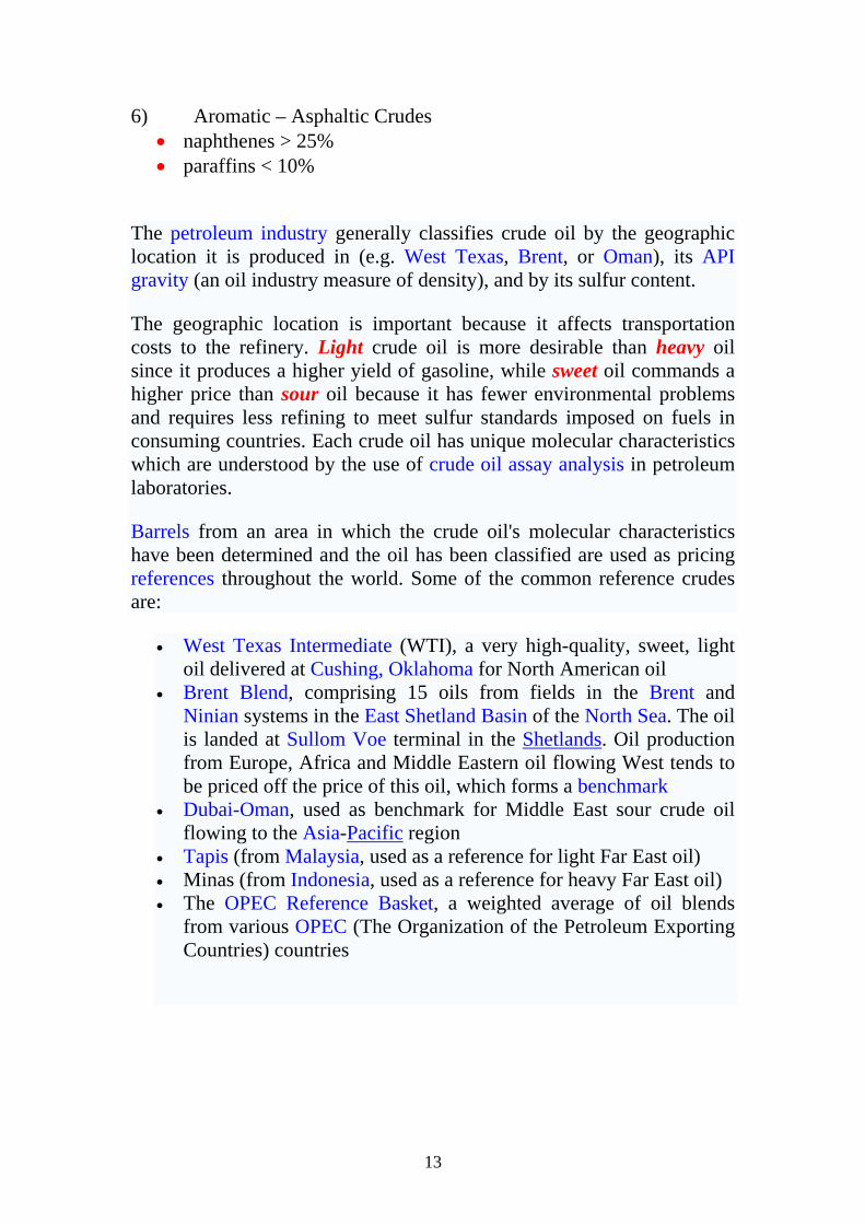
6) Aromatic – Asphaltic Crudes • naphthenes > 25% • paraffins < 10%
The petroleum industry generally classifies crude oil by the geographic location it is produced in (e.g. West Texas, Brent, or Oman), its API gravity (an oil industry measure of density), and by its sulfur content.
The geographic location is important because it affects transportation costs to the refinery. Light crude oil is more desirable than heavy oil since it produces a higher yield of gasoline, while sweet oil commands a higher price than sour oil because it has fewer environmental problems and requires less refining to meet sulfur standards imposed on fuels in consuming countries. Each crude oil has unique molecular characteristics which are understood by the use of crude oil assay analysis in petroleum laboratories.
Barrels from an area in which the crude oil's molecular characteristics have been determined and the oil has been classified are used as pricing references throughout the world. Some of the common reference crudes are:
• West Texas Intermediate (WTI), a very high-quality, sweet, light oil delivered at Cushing, Oklahoma for North American oil
• Brent Blend, comprising 15 oils from fields in the Brent and Ninian systems in the East Shetland Basin of the North Sea. The oil is landed at Sullom Voe terminal in the Shetlands. Oil production from Europe, Africa and Middle Eastern oil flowing West tends to be priced off the price of this oil, which forms a benchmark
• Dubai-Oman, used as benchmark for Middle East sour crude oil flowing to the Asia-Pacific region
• Tapis (from Malaysia, used as a reference for light Far East oil) • Minas (from Indonesia, used as a reference for heavy Far East oil) • The OPEC Reference Basket, a weighted average of oil blends
from various OPEC (The Organization of the Petroleum Exporting Countries) countries

14
• oAPI
Crude oils are also defined in terms of API (American Petroleum Institute) gravity.The higher the API gravity, the lighter the crude. For example, light crude oils have high API gravities, generally exceed 38
oAPI and low specific gravities. Crude oils with low carbon, high hydrogen, and high API gravity are usually rich in paraffins and tend to yield greater proportions of gasoline and light petroleum products. Heavy crude oils are commonly with API gravity of 22 degrees or lower. Crude oils with high carbon, low hydrogen, and low API gravities are usually rich in aromatics. Intermediate crude oils fall in range of 22 degree to 38 oAPI gravity.
oAPI = (141.5/SG 15oF) – 131.5
Crude Oils oAPI = 10 – 50 Higher oAPI, more paraffinic crude, higher yields of gasoline. Lower oAPI, more aromatic crude, lower yields of gasoline.
• Sulfur Content
Crude oil naturally contains sulfur compounds. Crudes are classed as sweet or sour depending on their sulfur content. If a crude has less than 0.5% sulfur in it, it is considered to be "sweet". If has greater than 2.5% sulfur, it is "sour". A crude with a sulfur content between these two endpoints is called "intermediate".
• Pour Point, °F (°C)
The pour point of the crude oil, in °F or °C, is a rough indicator of the relative paraffinicity and aromaticity of the crude. The lower the pour point, the lower the paraffin content and the greater the content of aromatics.
• Carbon Residue, wt% Carbon residue is determined by distillation to a coke residue in the absence of air. The carbon residue is roughly related to the asphalt content of the crude and to the quantity of the lubricating oil fraction that can be recovered. In most cases the lower the carbon residue, the more valuable the crude. This is expressed in terms of the weight percent carbon residue by either the Ramsbottom (RCR) or Conradson (CCR) ASTM test procedures (D-524 and D-189).
15
• Salt Content, lb/1000 bbl
If the salt content of the crude, when expressed as NaCl, is greater than 10 lb/1000 bbl, it is generally necessary to desalt the crude before processing. If the salt is not removed, severe corrosion problems may be encountered. If residua are processed catalytically, desalting is desirable at even lower salt contents of the crude. Although it is not possible to have an accurate conversion unit between lb/1000 bbl and ppm by weight because of the different densities of crude oils, 1lb/1000 bbl is approximately 3 ppm.
• Characterization Factors
There are several correlations between yield and the aromaticity and paraffinicity of crude oils, but the two most widely used are the UOP or Watson ‘‘characterization factor’’ (KW) and the U.S. Bureau of Mines ‘‘correlation index’’ (CI).
This method is for calculating the UOP Characterization Factor of petroleum oils from API gravity and distillation data. The UOP Characterization Factor, commonly called KUOP, is indicative of the general origin and nature of a petroleum stock.
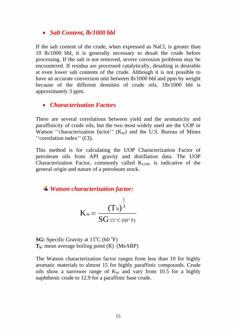
Watson characterization factor:
SG: Specific Gravity at 15oC (60 oF) Tb: mean average boiling point (R) (MeABP) The Watson characterization factor ranges from less than 10 for highly aromatic materials to almost 15 for highly paraffinic compounds. Crude oils show a narrower range of KW and vary from 10.5 for a highly naphthenic crude to 12.9 for a paraffinic base crude.
F)(60 C15
31
b w
SG)(T K
°°=
16
UOP characterization factor: Kuop has the same expression as Kw, but Tb transfer to Volume average boiling point (VABP) Additional notes related to the application of the above characterization factors:
• Aromatics would have lower KUOP • The use of boiling point indicates a relationship to the interactive
forces between the molecules. • The use of specific gravity relates to how tightly the molecules are
packed (i.e. density)
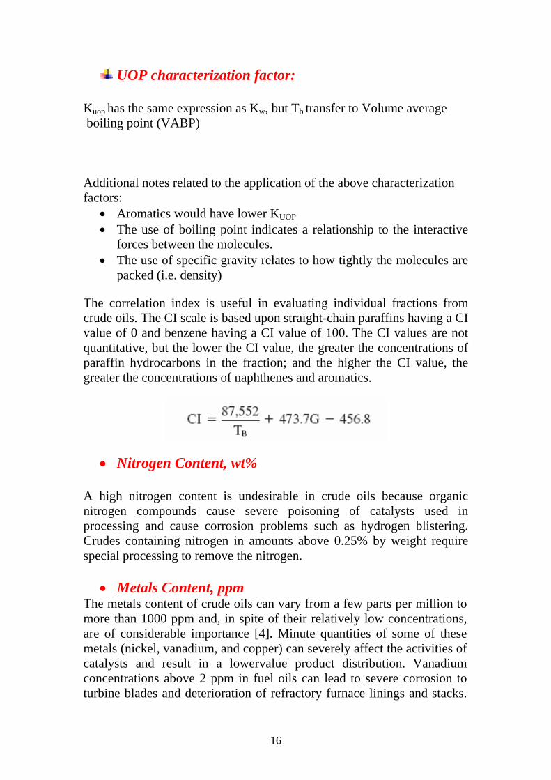
The correlation index is useful in evaluating individual fractions from crude oils. The CI scale is based upon straight-chain paraffins having a CI value of 0 and benzene having a CI value of 100. The CI values are not quantitative, but the lower the CI value, the greater the concentrations of paraffin hydrocarbons in the fraction; and the higher the CI value, the greater the concentrations of naphthenes and aromatics.
• Nitrogen Content, wt% A high nitrogen content is undesirable in crude oils because organic nitrogen compounds cause severe poisoning of catalysts used in processing and cause corrosion problems such as hydrogen blistering. Crudes containing nitrogen in amounts above 0.25% by weight require special processing to remove the nitrogen.
• Metals Content, ppm The metals content of crude oils can vary from a few parts per million to more than 1000 ppm and, in spite of their relatively low concentrations, are of considerable importance [4]. Minute quantities of some of these metals (nickel, vanadium, and copper) can severely affect the activities of catalysts and result in a lowervalue product distribution. Vanadium concentrations above 2 ppm in fuel oils can lead to severe corrosion to turbine blades and deterioration of refractory furnace linings and stacks.

17
Distillation concentrates the metallic constituents of crude in the residues, but some of the organometallic compounds are actually volatilized at refinery distillation temperatures and appear in the higher-boiling distillates. The metallic content may be reduced by solvent extraction with propane or similar solvents as the organometallic compounds are precipitated with the asphaltenes and resins.
• Distillation Range
The boiling range of the crude gives an indication of the quantities of the various products present. The most useful type of distillation is known as a true boiling point (TBP) distillation and generally refers to a distillation performed in equipment that accomplishes a reasonable degree of fractionation. There is no specific test procedure called a TBP distillation, but the U.S. Bureau of Mines Hempel and ASTM D-285 distillations are the tests most commonly used. Neither of these specify either the number of theoretical plates or the reflux ratio used and, as a result, there is a trend toward using the results of a 15:5 distillation (D- 2892) rather than the TBP. The 15:5 distillation is carried out using 15 theoretical plates at a reflux ratio of 5: 1. The crude distillation range also has to be correlated with ASTM distillations because product specifications are generally based on the simple ASTM distillation tests D-86 and D-1160. The TBP cut point for various fractions can be approximated by use of Figure 1. .
Figure 1: Approximate cut points of petroleum fractions
18
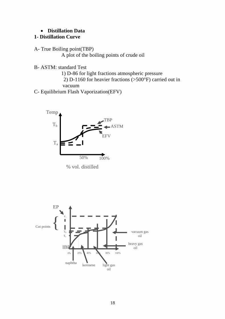
• Distillation Data 1- Distillation Curve A- True Boiling point(TBP)
A plot of the boiling points of crude oil B- ASTM: standard Test 1) D-86 for light fractions atmospheric pressure 2) D-1160 for heavier fractions (>500°F) carried out in vacuum C- Equilibrium Flash Vaporization(EFV)
% vol. distilled
Ta
Tb
Te
Cut points { EP
IBP 0% 20% 40% 60% 80% 100%
naphtha kerosene light gasoil
heavy gasoil
vacuum gasoil
Ta
Tb
50% 100%
Temp
ASTMTBP
EFV

19
Home work: For the given crude oil; 1- Draw a TBP curve. 2- Evaluate the crude. 3- Estimate the % yields of the fractions that could be obtained from processing this crude in an atmospheric distillation colum if the feed temperature is 650 oF.
spg Vol.% Distilled
TBP(oF)
0.6 0.697 0.759 0.781 0.791 0.806 0.832 0.848 0.860 0.867 0.872 0.878 0.887 0.893 0.933 0.995
2.6 1.5 4.1 4.0 3.0 3.9 4.0 4.0 4.0 4.0 4.1 2.0 2.0 1.8 31.8 23.2
- 97 97-178 178-242 242-269 269-342 342-395 395-438 438-479 479-518 518-557 557-594 594-610 610-632 632-650 650-1000
1000+
Note: More problems on classification of crude oil will be given in class
20
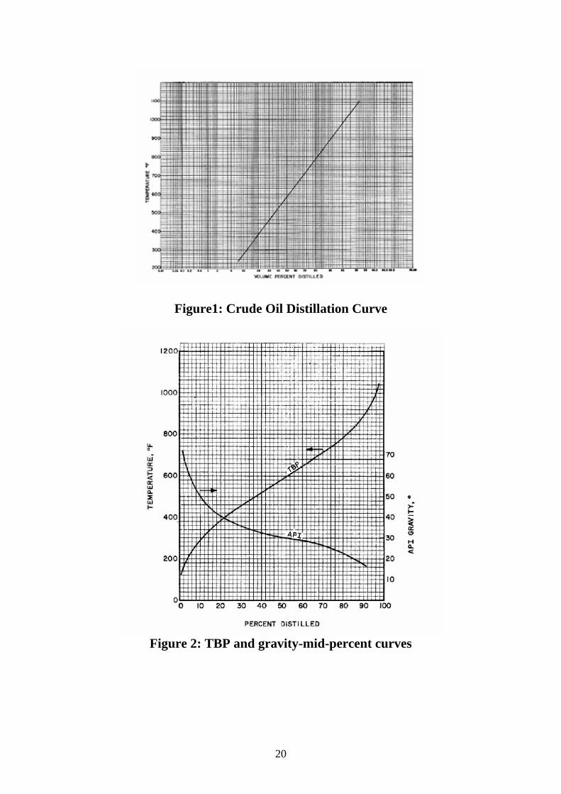
Figure1: Crude Oil Distillation Curve
Figure 2: TBP and gravity-mid-percent curves

21
Figure 3: Boiling point at 760 mmHg versus boiling point at 40 mmHg.
Figure 4: Mean average boiling point of petroleum fractions.
22
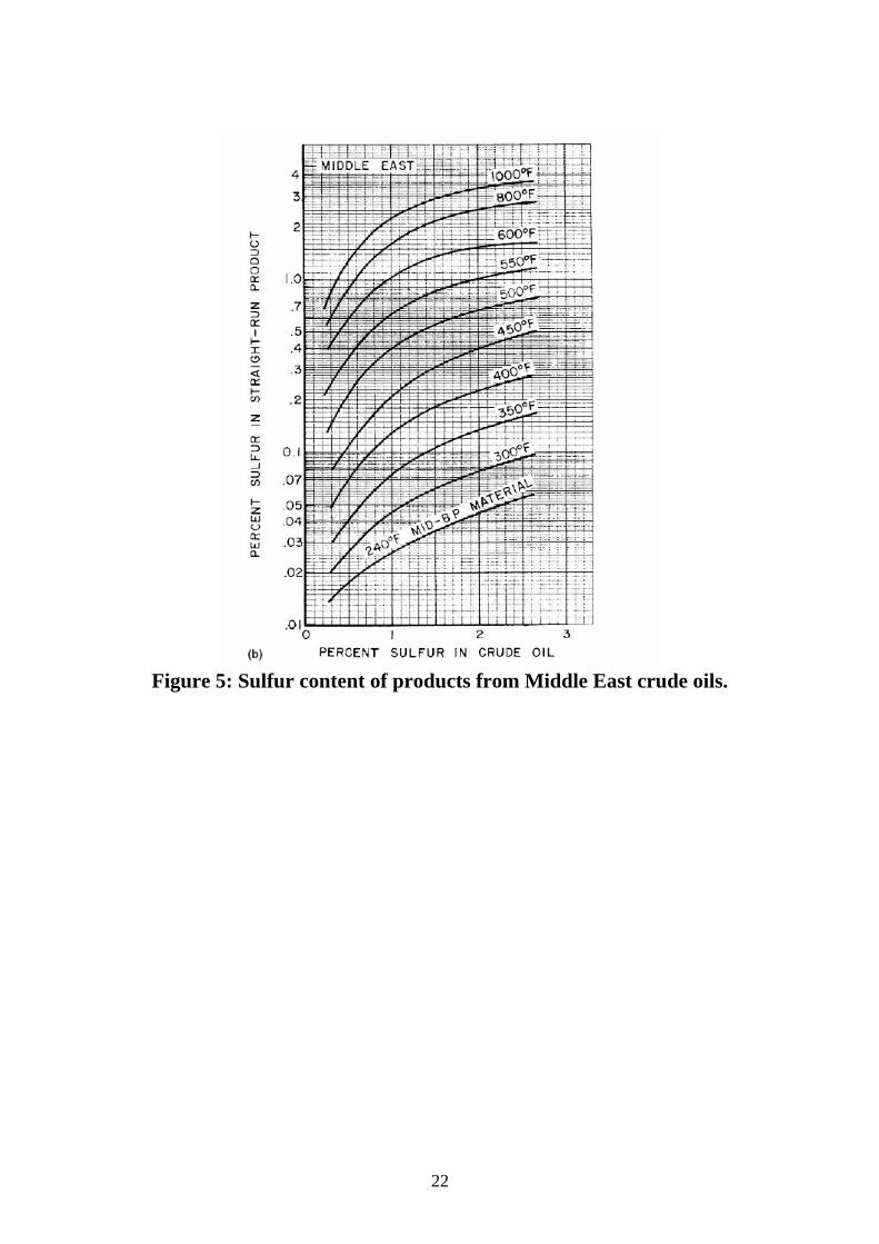
Figure 5: Sulfur content of products from Middle East crude oils.
23
Lecture 5
Crude oil refinery processes The Refining Process
As mentioned previously, a barrel of crude oil has a mixture of all sorts of hydrocarbons in it. Oil refining separates everything into useful substances. The petroleum refining industry converts crude oil into more than 2500 refined products, including liquefied petroleum gas, gasoline, kerosene, aviation fuel, diesel fuel, fuel oil, lubricating oil and petrochemical industry feedstock. Petroleum refining activities start with receipt of the crude oil at the refinery, followed by multiple petroleum handling and refining operations and terminate with storage of the refined products prior to shipment.
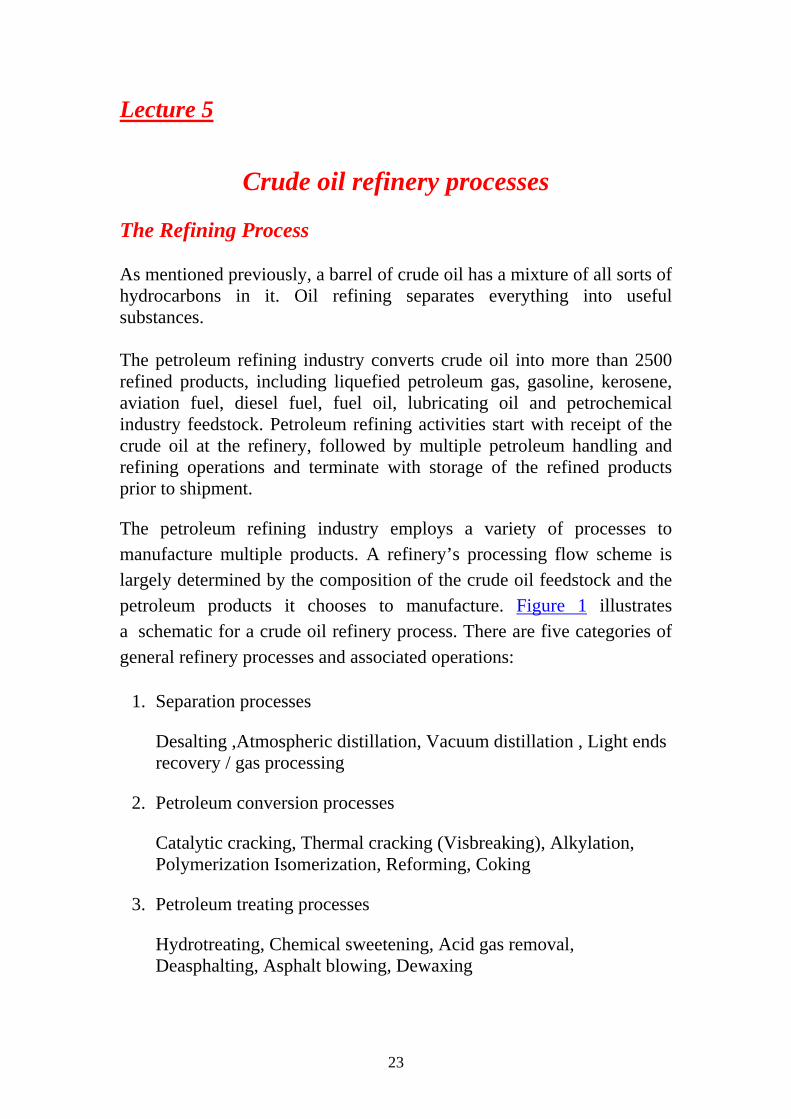
The petroleum refining industry employs a variety of processes to manufacture multiple products. A refinery’s processing flow scheme is largely determined by the composition of the crude oil feedstock and the petroleum products it chooses to manufacture. Figure 1 illustrates a schematic for a crude oil refinery process. There are five categories of general refinery processes and associated operations:
1. Separation processes
Desalting ,Atmospheric distillation, Vacuum distillation , Light ends recovery / gas processing
2. Petroleum conversion processes
Catalytic cracking, Thermal cracking (Visbreaking), Alkylation, Polymerization Isomerization, Reforming, Coking
3. Petroleum treating processes
Hydrotreating, Chemical sweetening, Acid gas removal, Deasphalting, Asphalt blowing, Dewaxing
24
4. Feedstock and product handling
Storage, Blending, Loading, Unloading
Figure 1: Overall Refinery flow
25
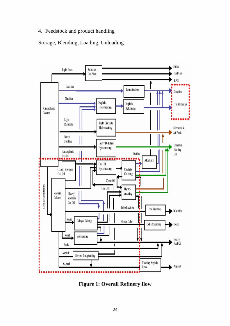
CRUDE OIL PRETREATMENT (DESALTING).
a. Crude oil often contains water, inorganic salts, suspended solids, and water-soluble trace metals. As a first step in the refining process, to reduce corrosion, plugging, and fouling of equipment and to prevent poisoning the catalysts in processing units, these contaminants must be removed by desalting (dehydration).
b. The two most typical methods of crude-oil desalting, chemical and electrostatic separation, use hot water as the extraction agent. In chemical desalting, water and chemical surfactant (demulsifiers) are added to the crude, heated so that salts and other impurities dissolve into the water or attach to the water, and then held in a tank where they settle out. Electrical desalting is the application of high-voltage electrostatic charges to concentrate suspended water globules in the bottom of the settling tank. Surfactants are added only when the crude has a large amount of suspended solids. Both methods of desalting are continuous. A third and less-common process involves filtering heated crude using diatomaceous earth. c. The feedstock crude oil is heated to between 150° and 350°F to reduce viscosity and surface tension for easier mixing and separation of the water. The temperature is limited by the vapor pressure of the crude-oil feedstock. In both methods other chemicals may be added. Ammonia is often used to reduce corrosion. Caustic or acid may be added to adjust the pH of the water wash. Wastewater and contaminants are discharged from the bottom of the settling tank to the wastewater treatment facility. The desalted crude is continuously drawn from the top of the settling tanks and sent to the crude distillation (fractionating) tower.
Figure 2: Desalting of crude oil

26
Lecture 6&7
Industrial process furnaces An industrial furnace or direct fired heater, Fig.(1), is an equipment used to provide heat for a process or can serve as reactor which provides heats of reaction. Furnace designs vary as to its function, heating duty, type of fuel and method of introducing combustion air. However, most process furnaces have some common features.
Figure 1: Schematic diagram of an industrial process furnace
Fuel flows into the burner and is burnt with air provided from an air blower. There can be more than one burner in a particular furnace which can be arranged in cells which heat a particular set of tubes. Burners can also be floor mounted, wall mounted or roof mounted depending on design. The flames heat up the tubes, which in turn heat the fluid inside in the first part of the furnace known as the radiant section or firebox. In this chamber where combustion takes place, the heat is transferred mainly by radiation to tubes around the fire in the chamber. The heating fluid passes through the tubes and is thus heated to the desired temperature. The gases from the combustion are known as flue gas. After the flue gas leaves the

27
firebox, most furnace designs include a convection section where more heat is recovered before venting to the atmosphere through the flue gas stack. (HTF=Heat Transfer Fluid. Industries commonly use their furnaces to heat a secondary fluid with special additives like anti-rust and high heat transfer efficiency. This heated fluid is then circulated round the whole plant to heat exchangers to be used wherever heat is needed instead of directly heating the product line as the product or material may be volatile or prone to cracking at the furnace temperature.)
Radiant section
Figure 2: Middle of radiant section
The radiant section, Fig. (2), is where the tubes receive almost all its heat by radiation from the flame. In a vertical, cylindrical furnace, the tubes are vertical. Tubes can be vertical or horizontal, placed along the refractory wall, in the middle, etc., or arranged in cells. Studs are used to hold the insulation together and on the wall of the furnace. They are placed about 1 ft (300 mm) apart in this picture of the inside of a furnace. The tubes, shown below, which are reddish brown from corrosion, are carbon steel tubes and run the height of the radiant section. The tubes are a distance away from the insulation so radiation can be reflected to the back of the tubes to maintain a uniform tube wall temperature. Tube guides at the top, middle and bottom hold the tubes in place.

28
Convection section
Figure 3; Convection section
The convection section, Fig. (3), is located above the radiant section where it is cooler to recover additional heat. Heat transfer takes place by convection here, and the tubes are finned to increase heat transfer. The first two tube rows in the bottom of the convection section and at the top of the radiant section is an area of bare tubes (without fins) and are known as the shield section, so named because they are still exposed to plenty of radiation from the firebox and they also act to shield the convection section tubes, which are normally of less resistant material from the high temperatures in the firebox. The area of the radiant section just before flue gas enters the shield section and into the convection section called the bridgezone. Crossover is the term used to describe the tube that connects from the convection section outlet to the radiant section inlet. The crossover piping is normally located outside so that the temperature can be monitored and the efficiency of the convection section can be calculated. The sightglass at the top allows personnel to see the flame shape and pattern from above and visually inspect if flame impingement is occurring. Flame impingement happens when the flame touches the tubes and causes small isolated spots of very high temperature.

29
Burner
Figure 4: Furnace burner
The burner, Fig.(4), in the vertical, cylindrical furnace as above, is located in the floor and fires upward. Some furnaces have side fired burners, eg: train locomotive. The burner tile is made of high temperature refractory and is where the flame is contained in. Air registers located below the burner and at the outlet of the air blower are devices with movable flaps or vanes that control the shape and pattern of the flame, whether it spreads out or even swirls around. Flames should not spread out too much, as this will cause flame impingement. Air registers can be classified as primary, secondary and if applicable, tertiary, depending on when their air is introduced. The primary air register supplies primary air, which is the first to be introduced in the burner. Secondary air is added to supplement primary air. Burners may include a premixer to mix the air and fuel for better combustion before introducing into the burner. Some burners even use steam as premix to preheat the air and create better mixing of the fuel and heated air. The floor of the furnace is mostly made of a different material from that of the wall, typically hard castable refractory to allow technicians to walk on its floor during maintenance.
A furnace can be lit by a small pilot flame or in some older models, by hand. Most pilot flames nowadays are lit by an ignition transformer (much like a car's spark plugs). The pilot flame in turn lights up the main flame. The pilot flame uses natural gas while the main flame can use both

30
diesel and natural gas. When using liquid fuels, an atomizer is used, otherwise, the liquid fuel will simply pour onto the furnace floor and become a hazard. Using a pilot flame for lighting the furnace increases safety and ease compared to using a manual ignition method (like a match).
Sootblower
Sootblowers are found in the convection section. As this section is above the radiant section and air movement is slower because of the fins, soot tends to accumulate here. Sootblowing is normally done when the efficiency of the convection section is decreased. This can be calculated by looking at the temperature change from the crossover piping and at the convection section exit. Sootblowers utilize flowing media such as water, air or steam to remove deposits from the tubes. This is typically done during maintenance with the air blower turned on. There are several different types of sootblowers used. Wall blowers of the rotary type are mounted on furnace walls protruding between the convection tubes. The lances are connected to a steam source with holes drilled into it at intervals along its length. When it is turned on, it rotates and blows the soot off the tubes and out through the stack.
Stack
Figure 5: Stack damper

31
The flue gas stack, Fig.(5), is a cylindrical structure at the top of all the heat transfer chambers. The breeching directly below it collects the flue gas and brings it up high into the atmosphere where it will not endanger personnel.
The stack damper contained within works like a butterfly valve and regulates draft (pressure difference between air intake and air exit)in the furnace, which is what pulls the flue gas through the convection section. The stack damper also regulates the heat lost through the stack. As the damper closes, the amount of heat escaping the furnace through the stack decreases, but the pressure or draft in the furnace increases which poses risks to those working around it if there are air leakages in the furnace, the flames can then escape out of the firebox or even explode if the pressure is too great.
Insulation
Insulation is an important part of the furnace because it prevents excessive heat loss. Refractory materials such as firebrick, castable refractories and ceramic fibre, are used for insulation. The floor of the furnace are normally castable type refractories while those on the walls are nailed or glued in place. Ceramic fibre is commonly used for the roof and wall of the furnace and is graded by its density and then its maximum temperature rating. For eg: 8# 2,300°F means 8 lb/ft3 density with a maximum temperature rating of 2,300°F. An example of a castable composition is kastolite.
Fired heaters are an essential component of most process plants. They are primarily used to heat all types of hydrocarbons. They are also used to heat hot oils, steam, or air. Fired heaters are major consumers of energy and even the smallest improvements in efficiency can save thousands of dollars. In the refining industry, typical energy consumption is approximately 0.44 MM Btu/BBL of crude oil processed. This translates into 2667 MM Btu/hr for a 200,000-barrel-per-day (BPD) refinery. Even a 1% improvement in thermal efficiency translates into energy savings of $600,000 per year. Ethylene plants (22 MM Btu/ton of ethylene) and ammonia plants (28.5 MM Btu/ton of ammonia) are equally energy intensive.
Note: Problems on the design of fired heaters will be given in class

32
Lecture 8,9&10
Fractional Distillation The various components of crude oil have different sizes, weights and boiling temperatures; so, the first step is to separate these components. Because they have different boiling temperatures, they can be separated easily by a process called fractional distillation.
Fractional distillation is useful for separating a mixture of substances with narrow differences in boiling points, and is the most important step in the refining process.
Very few of the components come out of the fractional distillation column ready for market. Many of them must be chemically processed to make other fractions. For example, only 40% of distilled crude oil is gasoline; however, gasoline is one of the major products made by oil companies. Rather than continually distilling large quantities of crude oil, oil companies chemically process some other fractions from the distillation column to make gasoline; this processing increases the yield of gasoline from each barrel of crude oil.
Crude Distillation and light End Unit
Description. The first step in the refining process is the separation of crude oil into various fractions or straight-run cuts by distillation in atmospheric and vacuum towers. The main fractions or "cuts" obtained have specific boiling-point ranges and can be classified in order of decreasing volatility into gases, light distillates, middle distillates, gas oils, and residuum.
1. Atmospheric Distillation Tower.
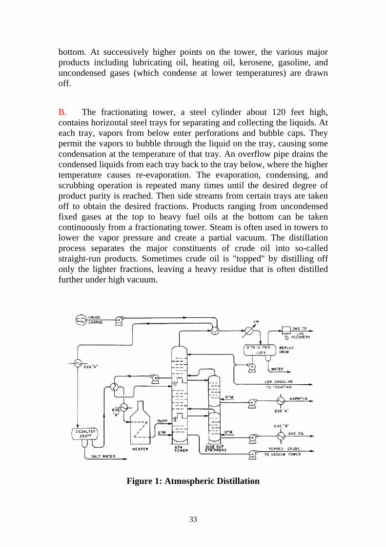
A. At the refinery, the desalted crude feedstock is preheated using recovered process heat. The feedstock then flows to a direct-fired crude charge heater where it is fed into the vertical distillation column just above the bottom, at pressures slightly above atmospheric and at temperatures ranging from 650° to 700° F (heating crude oil above these temperatures may cause undesirable thermal cracking). All but the heaviest fractions flash into vapor. As the hot vapor rises in the tower, its temperature is reduced. Heavy fuel oil or asphalt residue is taken from the
33
bottom. At successively higher points on the tower, the various major products including lubricating oil, heating oil, kerosene, gasoline, and uncondensed gases (which condense at lower temperatures) are drawn off.
B. The fractionating tower, a steel cylinder about 120 feet high, contains horizontal steel trays for separating and collecting the liquids. At each tray, vapors from below enter perforations and bubble caps. They permit the vapors to bubble through the liquid on the tray, causing some condensation at the temperature of that tray. An overflow pipe drains the condensed liquids from each tray back to the tray below, where the higher temperature causes re-evaporation. The evaporation, condensing, and scrubbing operation is repeated many times until the desired degree of product purity is reached. Then side streams from certain trays are taken off to obtain the desired fractions. Products ranging from uncondensed fixed gases at the top to heavy fuel oils at the bottom can be taken continuously from a fractionating tower. Steam is often used in towers to lower the vapor pressure and create a partial vacuum. The distillation process separates the major constituents of crude oil into so-called straight-run products. Sometimes crude oil is "topped" by distilling off only the lighter fractions, leaving a heavy residue that is often distilled further under high vacuum.
Figure 1: Atmospheric Distillation
34
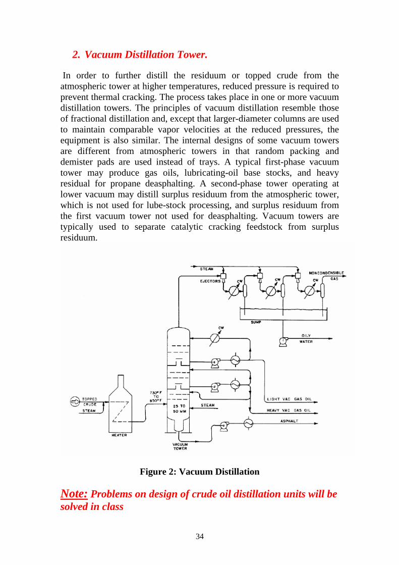
2. Vacuum Distillation Tower.
In order to further distill the residuum or topped crude from the atmospheric tower at higher temperatures, reduced pressure is required to prevent thermal cracking. The process takes place in one or more vacuum distillation towers. The principles of vacuum distillation resemble those of fractional distillation and, except that larger-diameter columns are used to maintain comparable vapor velocities at the reduced pressures, the equipment is also similar. The internal designs of some vacuum towers are different from atmospheric towers in that random packing and demister pads are used instead of trays. A typical first-phase vacuum tower may produce gas oils, lubricating-oil base stocks, and heavy residual for propane deasphalting. A second-phase tower operating at lower vacuum may distill surplus residuum from the atmospheric tower, which is not used for lube-stock processing, and surplus residuum from the first vacuum tower not used for deasphalting. Vacuum towers are typically used to separate catalytic cracking feedstock from surplus residuum.
Figure 2: Vacuum Distillation
Note: Problems on design of crude oil distillation units will be solved in class
35
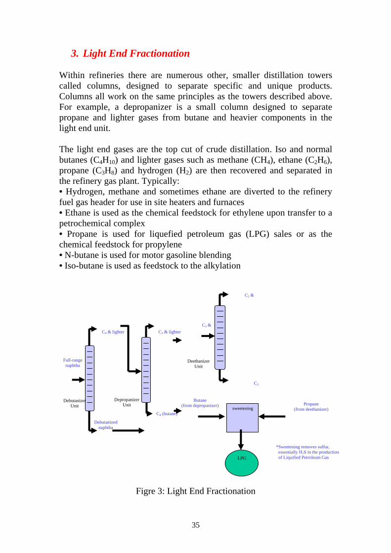
3. Light End Fractionation Within refineries there are numerous other, smaller distillation towers called columns, designed to separate specific and unique products. Columns all work on the same principles as the towers described above. For example, a depropanizer is a small column designed to separate propane and lighter gases from butane and heavier components in the light end unit. The light end gases are the top cut of crude distillation. Iso and normal butanes (C4H10) and lighter gases such as methane (CH4), ethane (C2H6), propane (C3H8) and hydrogen (H2) are then recovered and separated in the refinery gas plant. Typically: • Hydrogen, methane and sometimes ethane are diverted to the refinery fuel gas header for use in site heaters and furnaces • Ethane is used as the chemical feedstock for ethylene upon transfer to a petrochemical complex • Propane is used for liquefied petroleum gas (LPG) sales or as the chemical feedstock for propylene • N-butane is used for motor gasoline blending • Iso-butane is used as feedstock to the alkylation
Figre 3: Light End Fractionation
C3 &
C2 &
C3
DeethanizerUnit
Full-range naphtha
C4 & lighter
Debutanizer Unit
Debutanizednaphtha
C3 & lighter
Depropanizer Unit
C4 (butane)
Butane (from depropanizer) sweetening
Propane
(from deethanizer)
LPG
*Sweetening removes sulfur, essentially H2S in the production of Liquified Petroleum Gas

36
Lecture 11,12,&13
Conversion Processes
1- Cracking
Cracking is a petroleum refining process in which heavy-molecular weight hydrocarbons are broken up into light hydrocarbon molecules by the application of heat and pressure, with or without the use of catalysts, to derive a variety of fuel products. Cracking is one of the principal ways in which crude oil is converted into useful fuels such as motor gasoline, jet fuel, and home heating oil.
A. Thermal Cracking
Thermal cracking is a refining process in which heat (~800°C) and pressure (~700kPa) are used to break down, rearrange, or combine hydrocarbon molecules. The first thermal cracking process was developed around 1913. Distillate fuels and heavy oils were heated under pressure in large drums until they cracked into smaller molecules with better antiknock characteristics. However, this method produced large amounts of solid, unwanted coke. This early process has evolved into the following applications of thermal cracking: visbreaking, steam cracking, and coking.
a) Steam Cracking Process
Steam cracking is a petrochemical process sometimes used in refineries to produce olefinic raw materials (e.g., ethylene) from various feedstock for petrochemicals manufacture. The feedstock range from ethane to vacuum gas oil, with heavier feeds giving higher yields of by-products such as naphtha. The most common feeds are ethane, butane, and naphtha. Steam cracking is carried out at temperatures of 1,500°-1,600° F, and at pressures slightly above atmospheric. Naphtha produced from steam cracking contains benzene, which is extracted prior to hydrotreating. Residual from steam cracking is sometimes blended into heavy fuels.
b) Visbreaking Process
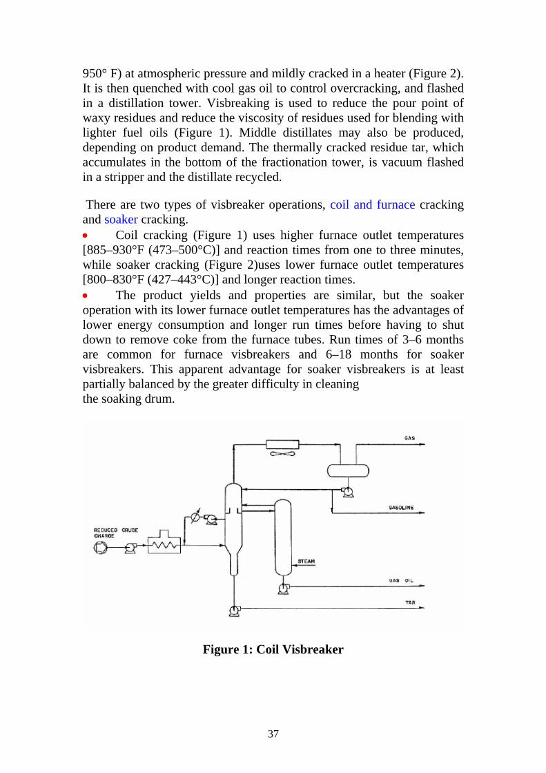
Visbreaking, a mild form of thermal cracking, significantly lowers the viscosity of heavy crude-oil residue without affecting the boiling point range. Residual from the atmospheric distillation tower is heated (800°-
37
950° F) at atmospheric pressure and mildly cracked in a heater (Figure 2). It is then quenched with cool gas oil to control overcracking, and flashed in a distillation tower. Visbreaking is used to reduce the pour point of waxy residues and reduce the viscosity of residues used for blending with lighter fuel oils (Figure 1). Middle distillates may also be produced, depending on product demand. The thermally cracked residue tar, which accumulates in the bottom of the fractionation tower, is vacuum flashed in a stripper and the distillate recycled.
There are two types of visbreaker operations, coil and furnace cracking and soaker cracking. • Coil cracking (Figure 1) uses higher furnace outlet temperatures [885–930°F (473–500°C)] and reaction times from one to three minutes, while soaker cracking (Figure 2)uses lower furnace outlet temperatures [800–830°F (427–443°C)] and longer reaction times. • The product yields and properties are similar, but the soaker operation with its lower furnace outlet temperatures has the advantages of lower energy consumption and longer run times before having to shut down to remove coke from the furnace tubes. Run times of 3–6 months are common for furnace visbreakers and 6–18 months for soaker visbreakers. This apparent advantage for soaker visbreakers is at least partially balanced by the greater difficulty in cleaning the soaking drum.
Figure 1: Coil Visbreaker

38
Figure 2: Soaker Visbreaker
c) Coking Processes
Coking is a severe method of thermal cracking used to upgrade heavy residuals into lighter products or distillates (Figure 3). Coking produces straight-run gasoline (coker naphtha) and various middle-distillate fractions used as catalytic cracking feedstock. The process so completely reduces hydrogen that the residue is a form of carbon called "coke." The two most common processes are delayed coking and continuous (contact or fluid) coking. Three typical types of coke are obtained (sponge coke, honeycomb coke, and needle coke) depending upon the reaction mechanism, time, temperature, and the crude feedstock.
1) Delayed Coking
In delayed coking (Figure 3) the heated charge (typically residuum from atmospheric distillation towers) is transferred to large coke drums which provide the long residence time needed to allow the cracking reactions to proceed to completion. Initially the heavy feedstock is fed to a furnace which heats the residuum to high temperatures (900°-950° F) at low pressures (25-30 psi) and is designed and controlled to prevent premature coking in the heater tubes (Figure 3). The mixture is passed from the heater to one or more coker drums where the hot material is held approximately 24 hours (delayed) at pressures of 25-75 psi, until it cracks into lighter products. Vapors from the drums are returned to a fractionator where gas, naphtha, and gas oils are separated out. The heavier

39
hydrocarbons produced in the fractionator are recycled through the furnace.
Figure 3: Delayed Coking
After the coke reaches a predetermined level in one drum, the flow is diverted to another drum to maintain continuous operation.
Delayed Coking Product Yields
Coke Yield (wt%) = 1.6 (wt% CCR) Gas (C4-) (wt%) = 7.8 + 0.144 (wt% CCR) Gasoline (wt%) = 11.29 + 0.343 (wt% CCR) Gas Oil (wt%) = 100 - (wt% Coke) - (wt% Gas) - (wt% Gasoline) 186.5 Gasoline (vol%) = —————— × (wt% Gasoline ) 131.5 + °API 155.5 Gas Oil (vol%) = —————— x (wt% Gas Oil) 131.5 + °API

40
Example:- What are the expected products from a delayed coker when running 100,000 bpd of the crude oil of 0.911 gravity? 1. Resid properties: 41.9 vol% yield 13.2 wt% CCR 1.004 gravity = 9.4°API 2.86 wt% Sulfur (est.) 2. Crude oil Feed: Mass = (100,000 bbl/day) . (42 gal/bbl) . (0.911) . (8.33718 lb/gal) = 31,900,000 lb/day 3. Coker Feed: Volume = (100,000 bbl/day ) . (0.419) = 41,900 bbl/day Mass = (41,900bbl/day) . (42 gal/bbl) . (1.004) . (8.33718 lb/gal) = 14,730,000 lb/day 14,730,000 Resid Yield = ————— = 46.2 wt% 31,900,000 4. Product yields: Coke Yield (wt%) = 1.6 . 13.2 = 21.12 wt% Gas (C4-) (wt%) = 7.8 + 0.144 . 13.2 = 9.70 wt% Gasoline (wt%) = 11.29 + 0.343 . 13.2 = 15.82 wt% Gas Oil (wt%) = 100 - 21.12 - 9.70 - 15.82 = 53.36 wt% 186.5 Gasoline (vol%) = ————— . 15.82 = 20.93 vol% 131.5 + 9.4 155.5 Gas Oil (vol%) = ————— . 53.36 = 58.88 vol% 131.5 + 9.4
41
2) Continuous Coking
Continuous (contact or fluid) coking is a moving-bed process that operates at temperatures higher than delayed coking. In continuous coking, thermal cracking occurs by using heat transferred from hot, recycled coke particles to feedstock in a radial mixer, called a reactor, at a pressure of 50 psi. Gases and vapors are taken from the reactor, quenched to stop any further reaction, and fractionated. The reacted coke enters a surge drum and is lifted to a feeder and classifier where the larger coke particles are removed as product. The remaining coke is dropped into the preheater for recycling with feedstock. Coking occurs both in the reactor and in the surge drum. The process is automatic in that there is a continuous flow of coke and feedstock.
B. Catalytic Cracking Catalytic cracking breaks complex hydrocarbons into simpler molecules in order to increase the quality and quantity of lighter, more desirable products and decrease the amount of residuals. This process rearranges the molecular structure of hydrocarbon compounds to convert heavy hydrocarbon feedstock into lighter fractions such as kerosene, gasoline, liquified petroleum gas (LPG), heating oil, and petrochemical feedstock.
Catalytic cracking is similar to thermal cracking except that catalysts facilitate the conversion of the heavier molecules into lighter products. Use of a catalyst in the cracking reaction increases the yield of improved-quality products under much less severe operating conditions than in thermal cracking. Typical temperatures are from 850°-950° F at much lower pressures of 10-20 psi. The catalysts used in refinery cracking units are typically solid materials (zeolite, aluminum hydrosilicate, treated bentonite clay, fuller's earth, bauxite, and silica-alumina) that come in the form of powders, beads, pellets or shaped materials called extrudites.
There are three basic functions in the catalytic cracking process:
• Reaction: Feedstock reacts with catalyst and cracks into different hydrocarbons;
• Regeneration: Catalyst is reactivated by burning off coke; and • Fractionation: Cracked hydrocarbon stream is separated into
various products.
The three types of catalytic cracking processes are fluid catalytic cracking (FCC), moving-bed catalytic cracking, and Thermofor catalytic cracking
42
(TCC). The catalytic cracking process is very flexible, and operating parameters can be adjusted to meet changing product demand. In addition to cracking, catalytic activities include dehydrogenation, hydrogenation, and isomerization.
a) Fluid Catalytic Cracking (FCC)
Fluid catalytic cracking or "cat cracking," is the basic gasoline-making process. Using intense heat (~1,000 oF), low pressure and a powdered catalyst, the cat cracker can convert most relatively heavy fractionÿÿÿÿto sÿÿllÿÿÿÿasÿÿinÿÿmolecules. The fÿÿid cracker consists of a catalyst section and a fractionating section that operate together as an integrated processing unit. The catalyst section contains the reactor and regenerator, which, with the standpipe and riser, forms the catalyst circulation unit. The fluid catalyst is continuously circulated between the reactor and the regenerator using air, oil vapors, and steam as the conveying media.
A typical FCC process (figure 4) involves mixing a preheated hydrocarbon charge with hot, regenerated catalyst as it enters the riser leading to the reactor. The charge is combined with a recycle stream within the riser, vaporized, and raised to reactor temperature (900°-1,000° F) by the hot catalyst. As the mixture travels up the riser, the charge is cracked at 10-30 psi. In the more modern FCC units, all cracking takes place in the riser. The "reactor" no longer functions as a reactor; it merely serves as a holding vessel for the cyclones. This cracking continues until the oil vapors are separated from the catalyst in the reactor cyclones. The resultant product stream (cracked product) is then charged to a fractionating column where it is separated into fractions, and some of the heavy oil is recycled to the riser.
Spent catalyst is regenerated to get rid of coke that collects on the catalyst during the process. Spent catalyst flows through the catalyst stripper to the regenerator, where most of the coke deposits burn off at the bottom where preheated air and spent catalyst are mixed. Fresh catalyst is added and worn-out catalyst removed to optimize the cracking process.
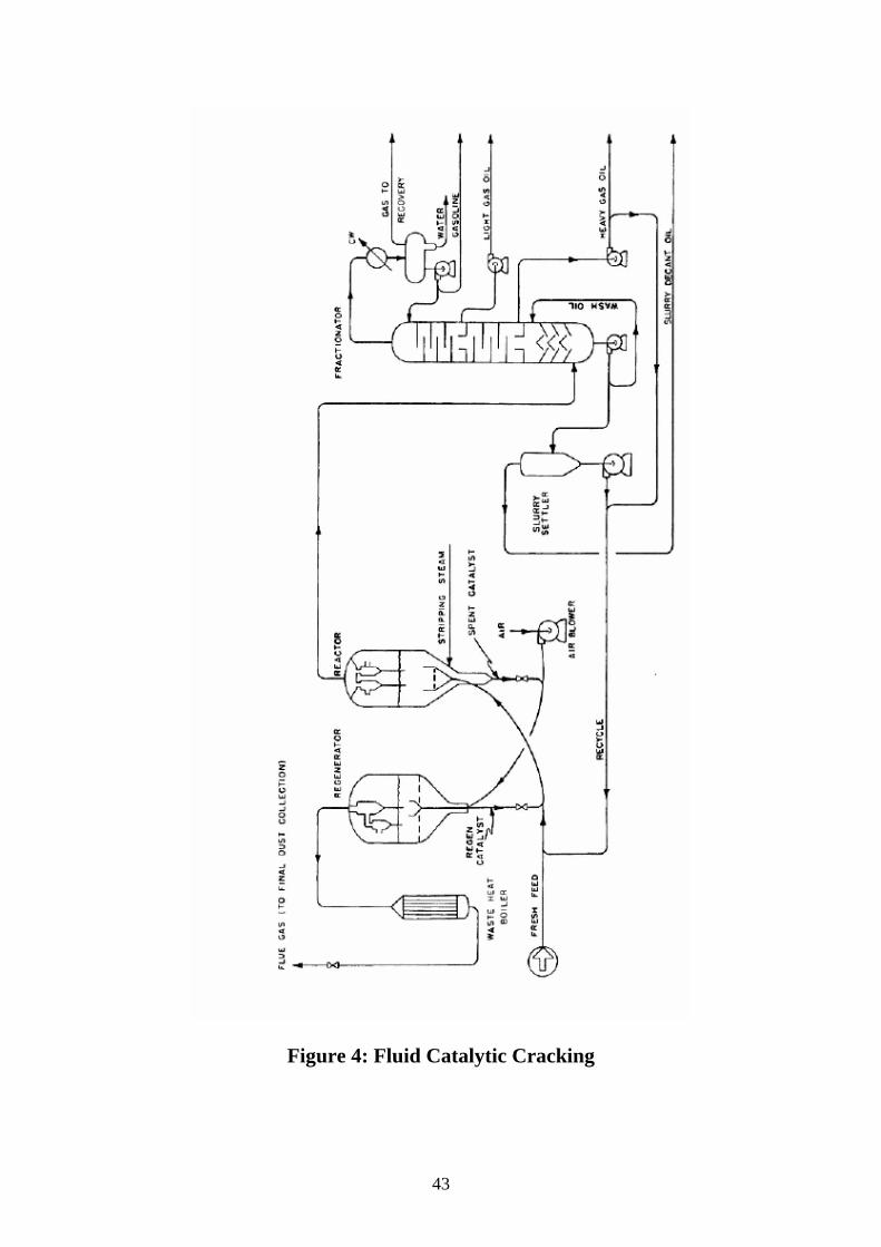
43
Figure 4: Fluid Catalytic Cracking

44
Figure 5: UOP FCC Style Unit
b) Moving Bed Catalytic Cracking
The moving-bed catalytic cracking process is similar to the FCC process. The catalyst is in the form of pellets that are moved continuously to the top of the unit by conveyor or pneumatic lift tubes to a storage hopper, then flow downward by gravity through the reactor, and finally to a regenerator. The regenerator and hopper are isolated from the reactor by steam seals. The cracked product is separated into recycle gas, oil, clarified oil, distillate, naphtha, and wet gas.
c) Thermofor Catalytic Cracking
In a typical thermofor catalytic cracking unit, the preheated feedstock flows by gravity through the catalytic reactor bed. The vapors are separated from the catalyst and sent to a fractionating tower. The spent catalyst is regenerated, cooled, and recycled. The flue gas from regeneration is sent to a carbon monoxide boiler for heat recovery.

45
PROCESS VARIABLES In addition to the nature of the charge stock, the major operating variables effecting the conversion and product distribution are the cracking temperature, catalyst/oil ratio, space velocity, catalyst type and activity, and recycle ratio. For a better understanding of the process, several terms should be defined. Activity: Ability to crack a gas oil to lower boiling fractions. Catalyst/oil ratio (C/O) : lb catalyst/lb feed. Conversion : 100 (volume of feed _ volume of cycle stock)/volume of feed. Cycle stock: Portion of catalytic-cracker effluent not converted to naphtha and lighter products [generally the material boiling above 430°F (220°C)] Efficiency : (% gasoline / %conversion) x 100. Recycle ratio : Volume recycle / volume fresh feed. Selectivity: The ratio of the yield of desirable products to the yield of undesirable products (coke and gas). Space velocity: Space velocity may be defined on either a volume (LHSV) or a weight (WHSV) basis. In a fluidized-bed reactor, the LHSV has little meaning because it is difficult to establish the volume of the bed. The weight of the catalyst in the reactor can be easily determined or calculated from the residence time and C/O ratio. LHSV : Liquid hour space velocity in volume feed/(volume catalyst) (hr). WHSV :(Weight hour space velocity in lb feed)/(lb catalyst) (hr). If t is the catalyst residence time in hours, then WHSV _ 1/(t)(C/O). Severity factor = (C/O) / WHSV Within the limits of normal operations, increasing
1- Reaction temperature 2- Catalyst/oil ratio 3- Catalyst activity 4- Contact time
results in an increase in conversion, while a decrease in space velocity increases conversion. It should be noted that an increase in conversion does not necessarily mean an increase in gasoline yield, as an increase in temperature above a certain level can increase conversion, coke and gas yields, and octane number of the gasoline but decrease gasoline yield.
46
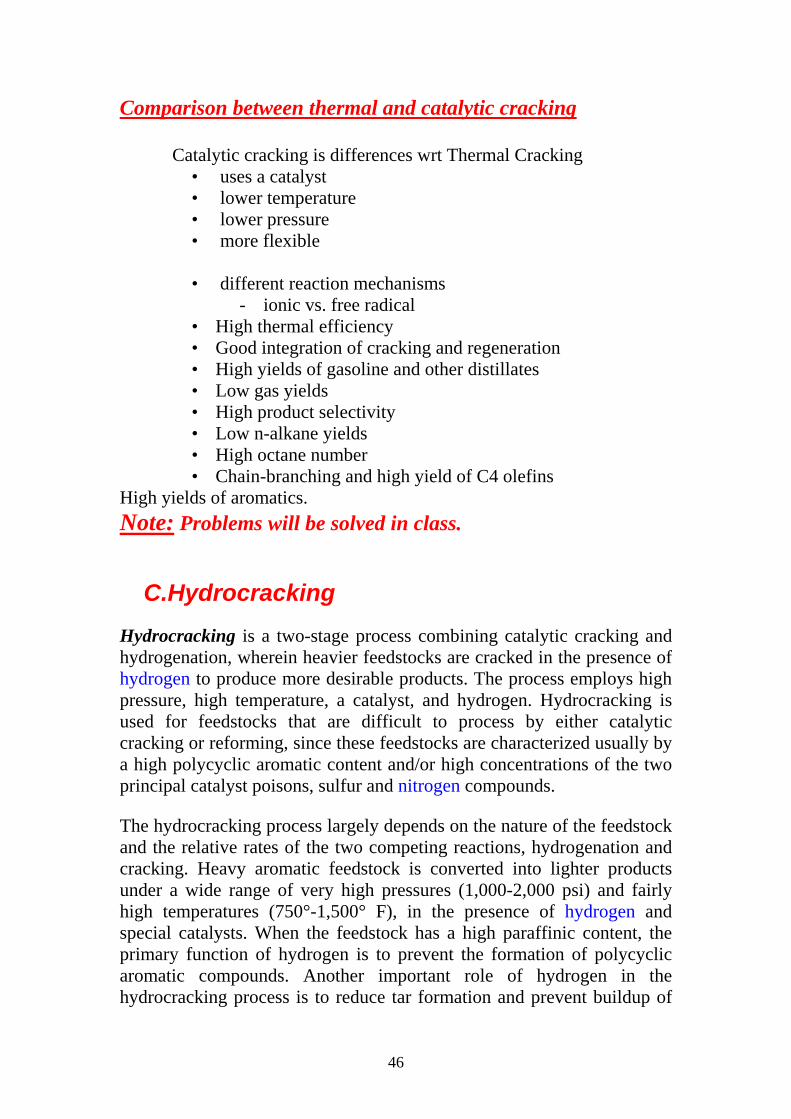
Comparison between thermal and catalytic cracking
Catalytic cracking is differences wrt Thermal Cracking • uses a catalyst • lower temperature • lower pressure • more flexible • different reaction mechanisms
- ionic vs. free radical • High thermal efficiency • Good integration of cracking and regeneration • High yields of gasoline and other distillates • Low gas yields • High product selectivity • Low n-alkane yields • High octane number • Chain-branching and high yield of C4 olefins
High yields of aromatics. Note: Problems will be solved in class.
C.Hydrocracking Hydrocracking is a two-stage process combining catalytic cracking and hydrogenation, wherein heavier feedstocks are cracked in the presence of hydrogen to produce more desirable products. The process employs high pressure, high temperature, a catalyst, and hydrogen. Hydrocracking is used for feedstocks that are difficult to process by either catalytic cracking or reforming, since these feedstocks are characterized usually by a high polycyclic aromatic content and/or high concentrations of the two principal catalyst poisons, sulfur and nitrogen compounds.
The hydrocracking process largely depends on the nature of the feedstock and the relative rates of the two competing reactions, hydrogenation and cracking. Heavy aromatic feedstock is converted into lighter products under a wide range of very high pressures (1,000-2,000 psi) and fairly high temperatures (750°-1,500° F), in the presence of hydrogen and special catalysts. When the feedstock has a high paraffinic content, the primary function of hydrogen is to prevent the formation of polycyclic aromatic compounds. Another important role of hydrogen in the hydrocracking process is to reduce tar formation and prevent buildup of
47
coke on the catalyst. Hydrogenation also serves to convert sulfur and nitrogen compounds present in the feedstock to hydrogen sulfide and ammonia.
Hydrocracking produces relatively large amounts of isobutane for alkylation feedstock. Hydrocracking also performs isomerization for pour-point control and smoke-point control, both of which are important in high-quality jet fuel.
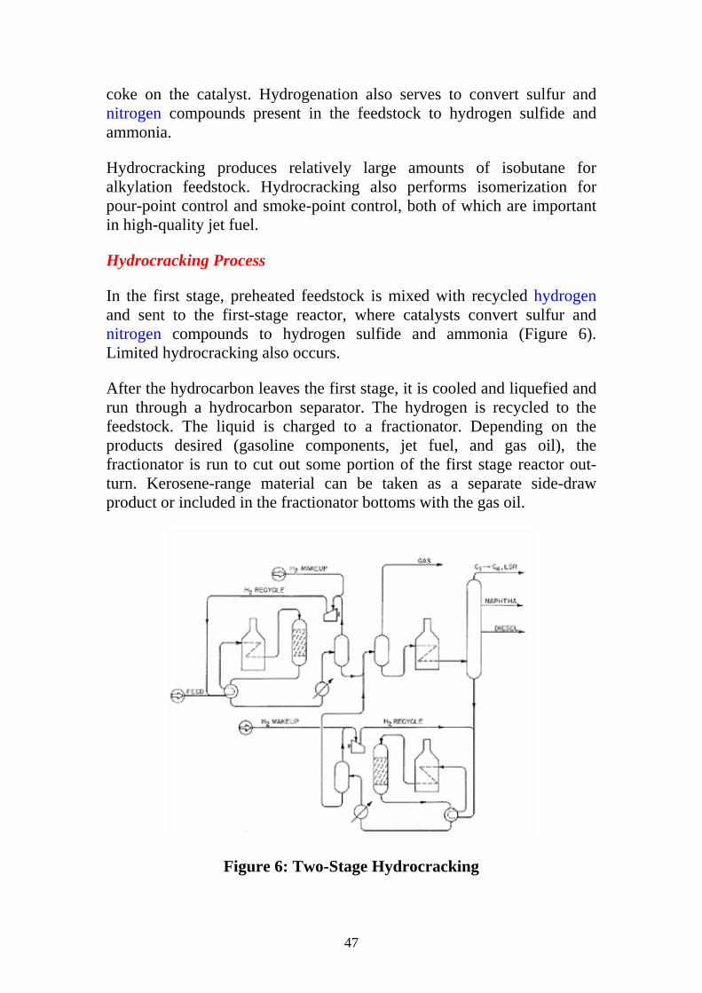
Hydrocracking Process
In the first stage, preheated feedstock is mixed with recycled hydrogen and sent to the first-stage reactor, where catalysts convert sulfur and nitrogen compounds to hydrogen sulfide and ammonia (Figure 6). Limited hydrocracking also occurs.
After the hydrocarbon leaves the first stage, it is cooled and liquefied and run through a hydrocarbon separator. The hydrogen is recycled to the feedstock. The liquid is charged to a fractionator. Depending on the products desired (gasoline components, jet fuel, and gas oil), the fractionator is run to cut out some portion of the first stage reactor out-turn. Kerosene-range material can be taken as a separate side-draw product or included in the fractionator bottoms with the gas oil.
Figure 6: Two-Stage Hydrocracking
48
The fractionator bottoms are again mixed with a hydrogen stream and charged to the second stage. Since this material has already been subjected to some hydrogenation, cracking, and reforming in the first stage, the operations of the second stage are more severe (higher temperatures and pressures). Like the outturn of the first stage, the second stage product is separated from the hydrogen and charged to the fractionator.
Difference between FCC and HYDCRC FCC HYDCRC
Carbon rejection Hydrogen addition
Endothermic Exothermic
Acid catalyst Metal catalyst on acid support
More gas less gas
More coke less coke but a costly process
2- Catalytic Reforming
Catalytic reforming is an important process used to convert low-octane naphthas into high-octane gasoline blending components called reformates. Reforming represents the total effect of numerous reactions such as cracking, polymerization, dehydrogenation, and isomerization taking place simultaneously Hydrogen, a significant by-product, is separated from the reformate for recycling and use in other processes.
Feedstock and Product Feedstock: Heavy Naphtha Paraffins 45-55 % Olefins 0-2 % Naphthenes 30-40 % Aromatics 5-10 %
Product: High Octane Gasoline: Paraffins 30-50 % Olefins 0 % Naphthenes 5 –10 % Aromatics 45-60 %

49
Most processes use platinum as the active catalyst. Sometimes platinum is combined with a second catalyst (bimetallic catalyst) such as rhenium or another noble metal.
There are many different commercial catalytic reforming processes including platforming, powerforming, ultraforming, and Thermofor catalytic reforming.
Reforming processes are classified as continuous, cyclic, or semiregenerative depending upon the frequency of catalyst regeneration. a) Continuous process: The equipment for the continuous process is designed to permit the removal and replacement of catalyst during normal operation. As a result, the catalyst can be regenerated continuously and maintained at a high activity. As increased coke laydown and thermodynamic equilibrium yields of reformate are both favored by low pressure operation, the ability to maintain high catalyst activities and selectivities by continuous catalyst regeneration is the major advantage of the continuous type of unit. This advantage has to be evaluated with respect to the higher capital costs and possible lower operating costs due to lower hydrogen recycle rates and pressures needed to keep coke laydown at an acceptable level. b) Semiregenerative Process: is at the other end of the spectrum and has the advantage of minimum capital costs. Regeneration requires the unit to be taken off-stream. Depending upon severity of operation, regeneration is required at intervals of 3 to 24 months. High hydrogen recycle rates and operating pressures are utilized to minimize coke laydown and consequent loss of catalyst activity. c) Cyclic process: is a compromise between these extremes and is characterized by having a swing reactor in addition to those on-stream in which the catalyst can be regenerated without shutting the unit down. When the activity of the catalyst in one of the on-stream reactors drops below the desired level, this reactor is isolated from the system and replaced by the swing reactor. The catalyst in the replaced reactor is then regenerated by admitting hot air into the reactor to burn the carbon off the catalyst. After regeneration it is used to replace the next reactor needing regeneration. In the cyclic processes, regeneration is typically performed on a 24- or 48-hour cycle, and a spare reactor is provided so that regeneration can be accomplished while the unit is still on-stream. Because of these extra facilities, the cyclic processes are more expensive

50
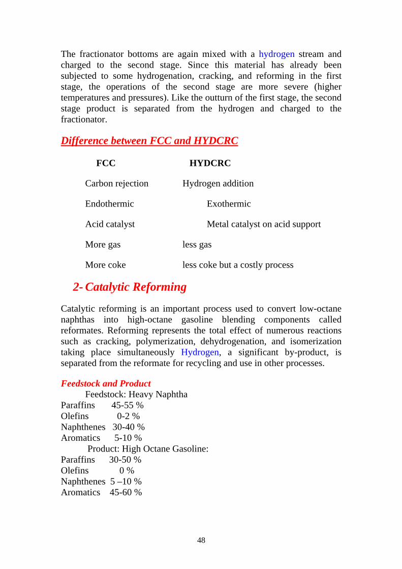
but offer the advantages of low pressure operation and higher yields of reformate at the same severity. Process Description The semiregenerative process is shown in the simplified process flow diagram given in Figure (7). The pretreated feed and recycle hydrogen are heated to 925 to 975°F (498–524°C) before entering the first reactor. In the first reactor, the major reaction is the dehydrogenation of naphthenes to aromatics and, as this is strongly endothermic, a large drop in temperature occurs. To maintain the reaction rate, the gases are reheated before being passed over the catalyst in the second reactor. As the charge proceeds through the reactors, the reaction rates decrease and the reactors become larger, and the reheat needed becomes less. Usually three or four reactors are sufficient to provide the desired degree of reaction and heaters are needed before each reactor to bring the mixture up to reaction temperature. In practice, either separate heaters can be used or one heater can contain several separate coils. A typical gas composition leaving each of the reactors in a four reactor system, with a HSR naphtha feed of 180–380°F; severity, 99 RON; and pressure, 163 psi (1124 kPa) is as follows:
The reaction mixture from the last reactor is cooled and the liquid products condensed. The hydrogen-rich gases are separated from the liquid phase in a drum separator, and the liquid from the separator is sent to a fractionator to be debutanized. The hydrogen-rich gas stream is split into a hydrogen recycle stream and a net hydrogen by-product which is used in hydrotreating or hydrocracking operations or as fuel. The reformer operating pressure and the hydrogen/feed ratio are compromises among obtaining maximum yields, long operating times between regeneration, and stable operation. It is usually necessary to operate at pressures from 50 to 350 psig (345–2415 kPa) and at hydrogen charge ratios of 3–8 mol H2/mol feed (2800–7600 scp/bbl). Liquid hourly space velocities in the area of 1 to 3 are in general use.
51
Figure 7: Catalytic Reforming, Semi-regenerative Process
Problem 1- Calculate the length of time between regeneration of catalyst in a reformer operating at the following conditions: Liquid hourly space velocity (LHSV) _ 3.0 v/hr/v, Feed rate _ 5000 BPSD, Feed gravity _ 55.0° API, Catalyst bulk density _ 50 lb/ft3, Number of reactors _ 3, Catalyst deactivates after processing 90 barrels of feed per pound of catalyst. 2- If the catalyst bed is 6 ft deep in each reactor, what are the reactor inside diameters? Assume an equal volume of catalyst in each reactor.
3- Catalytic hydrotreating
Catalytic hydrotreating is a hydrogenation process used to remove about 90% of contaminants such as nitrogen, sulfur, oxygen, and metals from liquid petroleum fractions. These contaminants, if not removed from the petroleum fractions as they travel through the refinery processing units, can have detrimental effects on the equipment, the catalysts, and the quality of the finished product. Typically, hydrotreating is done prior to processes such as catalytic reforming so that the catalyst is not contaminated by untreated feedstock. Hydrotreating is also used prior to catalytic cracking to reduce sulfur and improve product yields, and to
52
upgrade middle-distillate petroleum fractions into finished kerosene, diesel fuel, and heating fuel oils. In addition, hydrotreating converts olefins and aromatics to saturated compounds.
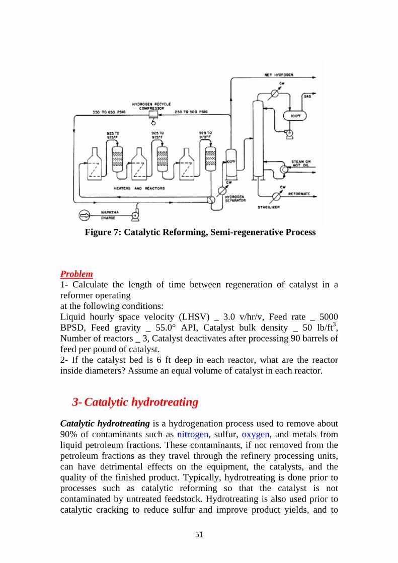
Hydrotreating for sulfur removal is called hydrodesulfurization. In a typical catalytic hydrodesulfurization unit, the feedstock is deaerated and mixed with hydrogen, preheated in a fired heater (600°-800° F) and then charged under pressure (up to 1,000 psi) through a fixed-bed catalytic reactor (Figure 8). In the reactor, the sulfur and nitrogen compounds in the feedstock are converted into hydrogen sulfide (H2S) and ammonia (NH3). The reaction products leave the reactor and after cooling to a low temperature enter a liquid/gas separator. The hydrogen-rich gas from the high-pressure separation is recycled to combine with the feedstock, and the low-pressure gas stream rich in H2S is sent to a gas treating unit where H2S is removed. The clean gas is then suitable as fuel for the refinery furnaces. The liquid stream is the product from hydrotreating and is normally sent to a stripping column for removal of H2S and other undesirable components. In cases where steam is used for stripping, the product is sent to a vacuum drier for removal of water. Hydrodesulfurized products are blended or used as catalytic reforming feedstock.
Figure 8: Catalytic Hydrodesulfurization
53
4- Other Hydrotreating Processes
Hydrotreating processes differ depending upon the feedstock available and catalysts used. Hydrotreating can be used to improve the burning characteristics of distillates such as kerosene. Hydrotreatment of a kerosene fraction can convert aromatics into naphthenes, which are cleaner-burning compounds.
Lube-oil hydrotreating uses catalytic treatment of the oil with hydrogen to improve product quality. The objectives in mild lube hydrotreating include saturation of olefins and improvements in color, odor, and acid nature of the oil. Mild lube hydrotreating also may be used following solvent processing. Operating temperatures are usually below 600° F and operating pressures below 800 psi. Severe lube hydrotreating, at temperatures in the 600°-750° F range and hydrogen pressures up to 3,000 psi, is capable of saturating aromatic rings, along with sulfur and nitrogen removal, to impart specific properties not achieved at mild conditions.
Hydrotreating also can be employed to improve the quality of pyrolysis gasoline (pygas), a by-product from the manufacture of ethylene.

54
Lecture 14
Gaseous Fuels
The Importance of Gaseous Fuel
- Generally VERY clean burning. Little soot. Operate with low XSA.
- Easy to burn - No grinding or atomisation. Excellent mixing
- No problems with erosion or corrosion
- No ash
- The gas is easy to clean. E.g. if sulphur is present, it may be easily removed prior to combustion.
- Simplest combustion plant of all - Burners
- Problems with distribution and storage
- Explosion risk - very volatile.
- Relatively costly. Offset by cheaper and more efficient plant.
Classification of Gaseous Fuels
(A) Fuels naturally found in nature:
Natural gas
Methane from coal mines
(B) Fuel gases made from solid fuel
Gases derived from Coal
Gases derived from waste and Biomass
From other industrial processes (Blast furnace gas)
(C) Gases made from petroleum
Liquefied Petroleum gas (LPG)

55
Refinery gases
Gases from oil gasification
(D) Gases from some fermentation process
Natural Gas
Natural gas is a gaseous fossil fuel consisting primarily of methane but including significant quantities of ethane, butane, propane, carbon dioxide, nitrogen, helium and hydrogen sulfide. It is found in oil fields and natural gas fields, and in coal beds. When methane-rich gases are produced by the anaerobic decay of non-fossil organic material, these are referred to as biogas. Natural gas is often informally referred to as simply gas, especially when compared to other energy sources such as electricity. Before natural gas can be used as a fuel, it must undergo extensive processing to remove almost all materials other than methane. The by-products of that processing include ethane, propane, butanes, pentanes and higher molecular weight hydrocarbons, elemental sulfur, and sometimes helium and nitrogen.
Chemical composition
The primary component of natural gas is methane (CH4), the shortest and lightest hydrocarbon molecule. It also contains heavier gaseous hydrocarbons such as ethane (C2H6), propane (C3H8) and butane (C4H10), as well as other sulphur containing gases, in varying amounts.
Component wt. %Methane (CH4) 80-95Ethane (C2H6) 5-15 Propane (C3H8) and Butane (C4H10) < 5
Nitrogen, helium, carbon dioxide and trace amounts of hydrogen sulfide, water and odorants can also be present. Mercury is also present in small amounts in natural gas extracted from some fields. The exact composition of natural gas varies between gas fields.
Organosulfur compounds and hydrogen sulfide are common contaminants which must be removed prior to most uses. Gas with a

56
significant amount of sulfur impurities, such as hydrogen sulfide, is termed sour gas; gas with sulfur or carbon dioxide impurities is acid gas. Processed natural gas that is available to end-users is tasteless and odorless, however, before gas is distributed to end-users, it is odorized by adding small amounts of thiols, to assist in leak detection. Processed natural gas is, in itself, harmless to the human body, however,
natural gas is a simple asphyxiant and can kill if it displaces air to the point where the oxygen content will not support life.
Natural gas can also be hazardous to life and property through an explosion.
Natural gas is lighter than air, and so tends to dissipate into the atmosphere. But when natural gas is confined, such as within a house, gas concentrations can reach explosive mixtures and, if ignited, result in blasts that could destroy buildings. Methane has a lower explosive limit of 5% in air, and an upper explosive limit of 15%.
Terms used to describe gases:
dry or lean - high methane content (less condensate)
wet - high concentration of higher hydrocarbons (C5 - C10)
sour - High concentration of H2S
sweet - low conc. of H2S
Total world production of natural gas in 1986 was 100 trillion m3. It is used as feed stock as well as fuel. It is preferred due to its high CV. Gas from coal mines is of equal quality to oil fields however it is much more difficult to extract. In 1961 220 mill m3 of coal nat gas were extracted in the UK. The North Sea gas has smashed the industry.
Natural gases can be liquefied for distribution by tanker. Liquefied natural gas (LNG) contains mostly methane, LPG (Liquefied petroleum gas) mostly butane and propane
Origin of natural gas
There are several theories about the origin of natural gas. Since natural gas often comes from localities near crude oil (oil-based natural gas) or coal deposits (carbon-based natural gas), most theories assume that natural gas was gradually released during the formation of coal or crude oil as a result of the gradual decomposition of organic materials. Theories

57
preferring organic origin therefore advocate that natural gas originates from vegetative and animal remains. This theory is supported by the fact that many underground oil deposits contain chemicals that are only known in plants that live on the Earths surface.
In contrast, inorganic theories assume that natural gas was created from inorganic substances by a succession of chemical reactions. Recently, American scientists have proposed another, so-called abiogenetic hypothesis according to which natural gas was created by the fission of hydrocarbons that came to our planet at the time it was formed from cosmic matter. These higher hydrocarbons gradually disintegrated into methane, which subsequently advanced as far as the Earth's surface.
Natural gas processing plant
There are a great many ways in which to configure the various unit processes used in the processing of raw natural gas. The block flow diagram , Fig. (1), is a generalized, typical configuration for the processing of raw natural gas from non-associated gas wells.
Figure 1: Natural gas processing plant
58
It shows how raw natural gas is processed into sales gas pipelined to the end user markets. It also shows how processing of the raw natural gas yields these byproducts:
• Natural gas condensate • Sulfur • Ethane • Natural gas liquids (NGL): propane, butanes and C5+ (which is the
commonly used term for pentanes plus higher molecular weight hydrocarbons) .
1- Raw natural gas is commonly collected from a group of adjacent wells and is first processed at that collection point for removal of free liquid water and natural gas condensate. The condensate is usually then transported to an oil refinery and the water is disposed of as wastewater.
2- The raw gas is then pipelined to a gas processing plant where the initial purification is usually the removal of acid gases (hydrogen sulfide and carbon dioxide). There a many processes that are available for that purpose as shown in the flow diagram, but amine treating is the most widely used process.
3- The acid gases removed by amine treating are then routed into a sulfur recovery unit which converts the hydrogen sulfide in the acid gas into elemental sulfur. There are a number of processes available for that conversion, but the Claus process is by far the one usually selected. The residual gas from the Claus process is commonly called tail gas and that gas is then processed in a tail gas treating unit (TGTU) to recover and recycle residual sulfur-containing compounds back into the Claus unit. Again, as shown in the flow diagram, there are a number of processes available for treating the Claus unit tail gas. The final residual gas from the TGTU is incinerated. Thus, the carbon dioxide in the raw natural gas ends up in the incinerator flue gas stack.
4- The next step in the gas processing plant is to remove water vapor from the gas using the either regenerable absorption in liquid triethylene glycol (TEG) or a Pressure Swing Adsorption (PSA) unit which is regenerable adsorption using a solid adsorbent. Another newer process using membranes may also be considered.
5- Mercury is then removed by using adsorption processes (as shown in the flow diagram) such as activated carbon or regenerable molecular sieves.

59
6- Nitrogen is next removed and rejected using one of the three processes indicated on the flow diagram:
7- The next step is to recover of the natural gas liquids (NGL) for which most large, modern gas processing plants use another cryogenic low temperature distillation process involving expansion of the gas through a turbo-expander followed by distillation in a demethanizing fractionating column. Some gas processing plants use lean oil absorption process rather than the cryogenic turbo-expander process.
8- The residue gas from the NGL recovery section is the final, purified sales gas which is pipelined to the end-user markets.
9- The recovered NGL stream is processes through a fractionation train consisting of three distillation towers in series: a dethanizer, a depropanizer and and a debutanizer. The overhead product from the deethanizer is ethane and the bottoms are fed to the depropanizer. The overhead product from the depropanizer is propane and the bottoms are fed to the debutanizer. The overhead product from the debutanizer is a mixture of normal and iso-butane, and the bottoms product is a C5+ mixture.
References: 1. Nelson, W.L., "Petroleum Refinery Engineering". 2. Bhaskara Rao, B.K. "Modern Petroleum Refinery
Processes". 3. Gary, H., And Glenn E. Handwerk, "Petroleum Refining
Technology and Economics. 4. Hobson, G. D.," Modern Petroleum Technology".