Impact of Fiber Bragg Grating As Dispersion Compensator · PDF fileImpact of Fiber Bragg...
7
© 2011 Ojuswini Arora, Dr.Amit Kumar Garg. This is a research/review paper, distributed under the terms of the Creative Commons Attribution-Noncommercial 3.0 Unported License http://creativecommons.org/licenses/by-nc/3.0/), permitting all non commercial use, distribution, and reproduction in any medium, provided the original work is properly cited. Global Journal of researches in engineering Volume 11 Issue 7 Version 1.0 December 2011 Type: Double Blind Peer Reviewed International Research Journal Publisher: Global Journals Inc. (USA) Online ISSN: 2249-4596 & Print ISSN: 0975-5861 Impact of Fiber Bragg Grating As Dispersion Compensator on the Receiver Characteristics By Ojuswini Arora, Dr.Amit Kumar Garg M.M.University, Mullana, Ambala Abstract - Among the promising advancements towards cost-effective long-haul transmission is the use of Fiber Bragg Gratings (FBGs) as the dispersion compensating module (DCM). In this paper we discuss the feasibility of long-haul Wavelength Division Multiplexing (WDM) optical transmission using FBGs for the dispersion compensation & the performance is analysed by comparing the results of the receivers. A 10 Gb/s Non Return To Zero (NRZ) signal is launched onto a 100 km long standard single mode fiber. Comparison of eye diagrams & Bit Error Rate (BER) show a marked improvement in the link performance due to compensation of dispersion. Keywords : Fiber Bragg gratings, optical fiber dispersion, optical filter, dispersion compensation, photodiode. ImpactofFiberBraggGratingAsDispersionCompensatorontheReceiverCharacteristics Strictly as per the compliance and regulations of : GJRE-F Classification : FOR Code: 100506 Electrical and Electronics engineering
Transcript of Impact of Fiber Bragg Grating As Dispersion Compensator · PDF fileImpact of Fiber Bragg...
© 2011 Ojuswini Arora, Dr.Amit Kumar Garg. This is a research/review paper, distributed under the terms of the Creative Commons Attribution-Noncommercial 3.0 Unported License http://creativecommons.org/licenses/by-nc/3.0/), permitting all non commercial use, distribution, and reproduction in any medium, provided the original work is properly cited.
Global Journal of researches in engineering
Volume 11 Issue 7 Version 1.0 December 2011 Type: Double Blind Peer Reviewed International Research Journal Publisher: Global Journals Inc. (USA) Online ISSN: 2249-4596 & Print ISSN: 0975-5861
Impact of Fiber Bragg Grating As Dispersion Compensator on the Receiver Characteristics
By Ojuswini Arora, Dr.Amit Kumar Garg
M.M.University, Mullana, Ambala
Abstract -
Among the promising advancements towards cost-effective long-haul transmission is the use of Fiber Bragg Gratings (FBGs) as the dispersion compensating module (DCM). In this paper we discuss the feasibility of long-haul Wavelength Division Multiplexing (WDM) optical transmission using FBGs for the dispersion compensation & the performance is analysed by comparing the results of the receivers. A 10 Gb/s Non Return To Zero (NRZ) signal is launched onto a 100 km long standard single mode fiber. Comparison of eye diagrams & Bit Error Rate (BER) show a marked improvement in the link performance due to compensation of dispersion.
Keywords :
Fiber Bragg gratings, optical fiber dispersion, optical filter, dispersion compensation, photodiode.
Impact of Fiber Bragg Grating As Dispersion Compensator on the Receiver Characteristics
Strictly as per the compliance and regulations of :
GJRE-F Classification : FOR Code: 100506
Electrical and Electronics engineering
Impact of Fiber Bragg Grating As Dispersion Compensator on the Receiver Characteristics
Ojuswini Aroraα, Dr.Amit Kumar GargΩ
Abstract - Among the promising advancements towards cost-effective long-haul transmission is the use of Fiber Bragg Gratings (FBGs) as the dispersion compensating module (DCM). In this paper we discuss the feasibility of long-haul Wavelength Division Multiplexing (WDM) optical transmission using FBGs for the dispersion compensation & the performance is analysed by comparing the results of the receivers. A 10 Gb/s Non Return To Zero (NRZ) signal is launched onto a 100 km long standard single mode fiber. Comparison of eye diagrams & Bit Error Rate (BER) show a marked improvement in the link performance due to compensation of dispersion. Keywords : Fiber Bragg gratings, optical fiber dispersion, optical filter, dispersion compensation, photodiode.
I. INTRODUCTION & PREVIOUS WORK
ispersion compensating fiber (DCF) is currently used as the standard solution for dispersion compensation in long-haul transmission links,
since it yields colourless, slope matched dispersion cancellation with negligible cascading impairments. However, DCF is also limited in optical input power to avoid nonlinear impairments, has a relatively high insertion loss and is bulky. Chirped FBGs could possibly replace DCF as the standard solution for in-line dispersion compensation. Chirped FBGs have a negligible nonlinearity, low insertion loss and small size [1-2]. Wavelength Division Multiplexing (WDM) systems where multiple light signals at different frequencies are simultaneously launched in an optical fiber, the highly-selective filtering capabilities of Bragg gratings combined with its all-fiber configuration and flexibility make this technology an ideal candidate. For telecommunication applications, FBG-components have already been used for purposes such as pump laser stabilizers to improve the performances of pump lasers in optical amplifiers [4], gain flattening filters to equalize the gain of optical amplifiers [5], highly selective filters for channel selection in dense WDM systems [6] and chromatic dispersion compensators for temporal pulse shaping in long-haul and/or high bit rate systems [7]. This potentially allows simpler erbium-doped fiber amplifier (EDFA) design by cascading the FBG and
Author αΩ :
Electronics & Communication Department, M.M.E.C, M.M.University, Mullana, Ambala.
E-mail α : [email protected]
E-mail Ω: [email protected]
transmission fiber without a mid-stage amplifier, resulting in a significant cost reduction.
The formation of permanent gratings in an optical fiber was first demonstrated by Hill et al. in 1978 at the Canadian Communications Research Centre (CRC), Ottawa, Ont., Canada, [1]. They launched intense Argon-ion laser radiation into a germania-doped fiber and observed that after several minutes an increase in the reflected light intensity occurred which grew until almost all the light was reflected from the fiber. Spectral measurements, done indirectly by strain and temperature tuning of the fiber grating, confirmed that a very narrowband Bragg grating filter had been formed over the entire 1-m length of fiber. This achievement, subsequently called “Hill gratings,” was an outgrowth of research on the nonlinear properties of germania-doped silica fiber. It established an unknown photosensitivity of Germania fiber, which prompted other inquires, several years later, into the cause of the fiber photo-induced refractivity and its dependence on the wavelength of the light which was used to the form the gratings. Detailed studies [11] show that the grating strength increased as the square of the light intensity, suggesting a two-photon process as the mechanism.
In the original experiments, laser radiation at 488 nm was reflected from the fiber end producing a standing wave pattern that formed the grating. A single photon at one-half this wavelength, namely at 244 nm in the ultraviolet, proved to be far more effective. Meltz et al. [5] showed that this radiation could be used to form gratings that would reflect any wavelength by illuminating the fiber through the side of the cladding with two intersecting beams of UV light; now, the period of the interference maxima and the index change was set by the angle between the beams and the UV wavelength rather than by the visible radiation which was launched into the fiber core. Moreover, the grating formation was found to be orders-of-magnitude more efficient. At first, the observation of photo-induced refractivity in fibers was only a scientific curiosity, but over time it has become the basis for a technology that now has a broad and important role in optical communications and sensor systems. Research into the underlying mechanisms of fiber photosensitivity and its uses is on-going in
many universities and industrial
laboratories in Europe, North and South America, Asia, and Australia. Several hundred photosensitivity and fiber
D
© 2011 Global Journals Inc. (US)
Globa
l Jo
urna
l of R
esea
rche
s in E
nginee
ring
Volum
e X
I Issue
vvvvVII
Version
I
19
( F)
201
1Dec
embe
r
grating related articles have appeared in the scientific literature and in the proceedings of topical conferences, workshops, and symposia. FBG‟s are
now commercially available and they have found key applications in routing, filtering, control, and amplification of optical signals in the next generation of high-capacity WDM telecommunication networks.
II.
PROPOSED WORK
•
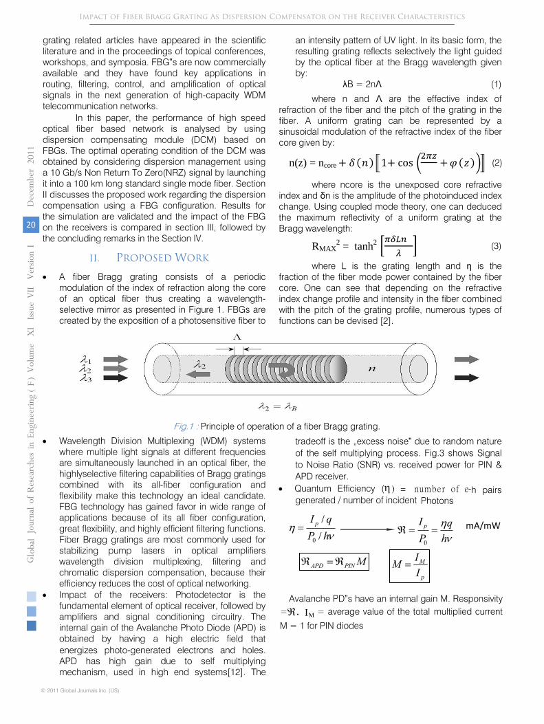
A fiber Bragg grating consists of a periodic modulation of the index of refraction along the core of an optical fiber thus creating a wavelength-selective mirror as presented in Figure 1. FBGs are created by the exposition of a photosensitive fiber to
an intensity pattern of UV light. In its basic form, the resulting grating reflects selectively the light guided by the optical fiber at the Bragg wavelength given by:
λB = 2nΛ
(1)
where n and Λ
are the effective index of refraction of the fiber and the pitch of the grating
in the fiber. A uniform grating can be represented by a sinusoidal modulation of the refractive index of the fiber core given by:
(2)
where ncore is the unexposed core refractive index and δn is the amplitude of the photoinduced index change. Using coupled mode theory, one can deduced the maximum reflectivity of a uniform grating at the Bragg wavelength:
(3)
where L is the grating length and η is the fraction of the fiber mode power contained by the fiber core. One can see that depending on the refractive index change profile and intensity in the fiber combined with the pitch of the grating profile, numerous types of functions can be devised [2].
Fig.1
:
Principle of operation of a fiber Bragg grating.
•
Wavelength Division Multiplexing (WDM) systems where multiple light signals at
different frequencies are simultaneously launched in an optical fiber, the highlyselective
filtering capabilities of Bragg gratings combined with its all-fiber
configuration and flexibility make this technology an ideal candidate. FBG
technology has gained favor in wide range of applications because of its all fiber
configuration, great flexibility, and highly efficient filtering functions. Fiber Bragg
gratings are most commonly used for stabilizing pump lasers in optical amplifiers
wavelength division multiplexing, filtering and chromatic dispersion compensation,
because their efficiency reduces the cost of optical networking.
•
Impact of the receivers: Photodetector is the fundamental element of optical
receiver, followed by amplifiers and signal conditioning circuitry. The internal gain of
the Avalanche Photo Diode (APD) is obtained by having a high electric field that
energizes photo-generated electrons and holes. APD has high gain due to self
multiplying mechanism, used in high end systems[12]. The
tradeoff is the „excess
noise‟
due to random nature of the self multiplying process. Fig.3 shows Signal to
Noise Ratio (SNR) vs. received power for PIN & APD receiver.
•
Quantum Efficiency ( ) = number of e-h pairs generated / number of incident
Photons
Impact of Fiber Bragg Grating As Dispersion Compensator on the Receiver Characteristics
mA/mW
0
/
/
pI qP h
0
pI qP h
APD PIN M M
p
IMI
Avalanche PD‟s have an internal gain M. Responsivity = = average value of the total multiplied current
M = 1 for PIN diodes
In this paper, the performance of high speed optical fiber based network is analysed by using dispersion compensating module (DCM) based on FBGs. The optimal operating condition of the DCM was obtained by considering dispersion management using a 10 Gb/s Non Return To Zero(NRZ) signal by launching it into a 100 km long standard single mode fiber. Section II discusses the proposed work regarding the dispersion compensation using a FBG configuration. Results for the simulation are validated and the impact of the FBG on the receivers is compared in section III, followed by the concluding remarks in the Section IV.
n(z) = ncore
RMAX2
= tanh2
. IM
© 2011 Global Journals Inc. (US)
Jo
urna
l of
Resea
rch e
s in E
nginee
ring
Volum
e X
I Issue
VII
Ver
sion
I
20
Gl oba
l
( F)
2011
Dec
embe
r
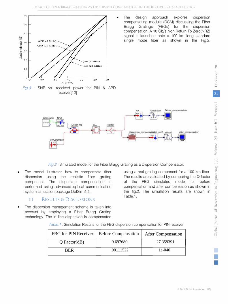
Fig.3
:
SNR vs. received power for PIN & APD receiver[12]
•
The design approach explores dispersion compensating module (DCM) discussing the Fiber Bragg Gratings (FBGs) for the dispersion compensation. A
10 Gb/s Non Return To Zero(NRZ) signal is launched onto a 100 km long standard single mode fiber as shown in the Fig.2.
Fig.2
:
Simulated model for the Fiber Bragg Grating as a Dispersion Compensator.
•
The model illustrates how to compensate fiber dispersion using the realistic fiber grating component. The dispersion compensation is performed using advanced optical communication system simulation package OptSim 5.2.
III.
RESULTS & DISCUSSIONS
•
The dispersion management scheme is taken into account by
employing a Fiber Bragg Grating technology. The in line dispersion is compensated
using a real grating component for a 100 km fiber. The results are validated by comparing the Q factor of the FBG simulated model for before compensation and after compensation as shown in the fig.2. The simulation results are shown in Table.1.
Table.1
:
Simulation Results for the FBG dispersion compensation for PIN receiver
© 2011 Global Journals Inc. (US)
Globa
l Jo
urna
l of R
esea
rche
s in E
nginee
ring
Volum
e X
I Issue
vvvvVII
Version
I
21
( F)
201
1
Impact of Fiber Bragg Grating As Dispersion Compensator on the Receiver Characteristics
FBG for PIN Receiver Before Compensation After Compensation
Q Factor(dB) 9.697680 27.359391
BER .00111522 1e-040
Dec
embe
r
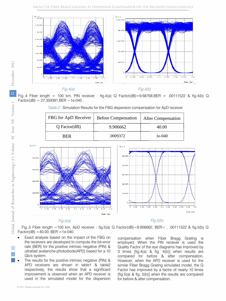
Fig..4 Fiber length =
100 km, PIN receiver : fig.4(a) Q Factor(dB)=9.68768,BER
= .00111522 & fig.4(b) Q Factor(dB) =
27.359391,BER =1e-040 .
Table.2 :
Simulation Results for the FBG dispersion compensation for ApD
receiver
Fig.5(a)
Fig.5(b)
Fig..5 Fiber length =100 km, ApD receiver : fig.5(a) Q Factor(dB)=9.906662, BER= . .00111522 & fig.5(b) Q Factor(dB) =40.00, BER =1e-040
•
Exact analysis based on the impact of the FBG on the receivers are developed to compute the bit-error rate (BER) for the positive intrinsic negative (PIN) & ultrafast avalanche-photodiode(APD) based for a 10 Gb/s system.
•
The results for the positive intrinsic negative (PIN) & APD receivers are shown in table1 & table2 respectively, the results show that a significant improvement is observed when an APD receiver is used in the simulated model for the dispersion
compensation when Fiber Bragg Grating is employed. When the PIN receiver is used the Quality Factor of the eye diagrams has improved by 3 times [fig.4(a) & fig. 4(b)] when results are compared for before & after compensation. However, when the APD receiver is used for the similar Fiber Bragg Grating simulated model, the Q Factor has improved by a factor of nearly 10 times [fig.5(a) & fig. 5(b)] when the results are compared for before & after compensation.
Impact of Fiber Bragg Grating As Dispersion Compensator on the Receiver Characteristics
Fig.4(a) Fig.4(b)
FBG for ApD Receiver Before Compensation
After Compensation
Q Factor(dB) 9.906662 40.00
BER .0009372 1e-040
© 2011 Global Journals Inc. (US)
Jo
urna
l of
Resea
rch e
s in E
nginee
ring
Volum
e X
I Issue
VII
Ver
sion
I
22
Gl oba
l
( F)
2011
Dec
embe
r
11.
Hill, K.O., Malo, B., Bilodeau, F., Johnson, D.C.,
and Albert, J., “Bragg gratings fabricated in monomode photosensitive optical fiber by UV exposure through a phase mask”, Applied Physics Letters, 62, no 10, pp. 1035-1037, March 8, 1993.
12.
Optical Receivers Theory and Operation ,Electrical and Computer Engineering Ryerson University.
13.
Guy, M., “Multi-Channel fiber Bragg gratings for dispersion and slope compensation”, OFC Conference Proceedings,(ThAA5), pp. 581-582, 2002.
14.
Paincahud, Y.et al ,“Superposition of chirped fiber Bragg grating for third order dispersion compensation over 32 WDM channels”, Electronics Letters, 38, no 24, pp. 1572-1573, November 21,2002.
15.
M. H. Eiselt, et al., “Performance Characterization of Components With Group Delay Fluctuations”, Photonic Technology Letters, vol. 15, pp. 1076-1078, 2003.
16.
D.van den Borne et al “Fiber Bragg Gratings for In-line Dispersion Compensation in Cost-effective 10.7-Gbit/s Long-Haul Transmission” Proceedings Symposium IEEE/LEOS Benelux Chapter, 2006, Eindhoven.
17.
Y.Painchaud, et al., “Low-penalty cascade of low-ripple FBG-based dispersion compensators, paper Th4.2.7”,ECOC 2006.
18.
H. S. Fews, et. al, “Experimental Comparison of Fibre and Grating-Based Dispersion CompensationSchemes for 40 channel 10Gb/s DWDM systems”, paper Th3.2.5, ECOC 2006.
19.
R. S. Kaler et al “Receiver sensitivity improvement using polarization-insensitive semiconductor optical amplifier” Opt. Eng. 45, 065007 ,Jun 07, 2006.
20.
Peng Sun et al, “Bit Error Rates for Ultrafast APD Based Optical Receivers: Exact and Large Deviation Based Asymptotic Approaches” IEEE Transactions on computers, vol. 57, no. 9, Sept. 2009.
© 2011 Global Journals Inc. (US)
Globa
l Jo
urna
l of R
esea
rche
s in E
nginee
ring
Volum
e X
I Issue
vvvvVII
Version
I
23
( F)
201
1
Impact of Fiber Bragg Grating As Dispersion Compensator on the Receiver Characteristics
REFERENCES REFERENCES REFERENCIAS
1. K. O. Hill and G. Meltz, “Fiber Bragg Grating technology fundamentals and overview” Journal of.Lightwave Technoogy., vol. 15, pp. 1263-1276, 1997.
2. C.Scheerer, et al., “Influence of Filter Group Delay Ripples on System Performance”, ECOC 1999, pp. I-410.
3. D.van den Borne, et al., "1.6-b/s/Hz Spectrally Efficient 40 x 85.6-Gb/s Transmission Over 1.700 km of SSMF Using POLMUX-RZ-DQPSK, PDP34, OFC 2006.
4. Ouellette, F., “Dispersion cancellation using linearly chirped Bragg grating filters in optical waveguides”, Optics Letters, 12, no 10, pp. 847-849, 1987.
5. Meltz, G., Morey, W.W., and Glenn, W.H., “Formation of Bragg gratings in optical fibers by a transverse holographic method”, Optics Letters, 14, no 16, pp. 823-825, 1989.
6. Hill, K.O., Fujii, Y., Johnson, D.C. and Kawasaki, B.S.,“Photosensitivity in optical fiber waveguides: Applications to reflection filter fabrication”, Applied Physics Letters, 32,no 10, pp. 647-649, May 15,
IV. CONCLUSIONS
It is shown in this paper that the recent advances in fiber Bragg grating technology now allow the realization of a high-performance, high speed optical fibers with good in line dispersion compensation. The system performance is evaluated for a 10 Gb/s system using a real grating component for the in line dispersioncompensation. Also, the impact of the FBG on the PIN & APD receivers is observed. The results demonstrate that the Q Factor has improved by a factor of nearly 10 times when a APD receiver is used as in comparison to the PIN receiver. However, this technology could be extended to other types of applications with the discovery of large photosensitivity in different material systems.
7. Kersey, A.D., Davis, M.A., Patrick, H.J., Leblanc, M., Koo,K.P., Askins, C.G., Putnam, M.A., and Friebele, E.J., “Fiber grating sensors”, Journal of Lightwave Technology, 15, no 8, pp. 1442-1463, August 1997.
8. Ventrudo, B.F., Rogers, G.A., Lick, G.S., Hargreaves, D., and Demayo, T.N., “Wavelength and intensity stabilisation of 980 nm diode lasers coupled to fibre Bragg gratings”, Electronics Letters, 30, no 25, pp. 2147-2149, December 8, 1994.
9. Rochette, M., Guy, M., Larochelle, S., Lauzon, J., and Trepanier, F., “Gain equalization of EDFAs with Bragg gratings”, Photonics Technology Letters, 11, no 5, pp. 536-538, May 1999.
1978.Kashyap, R., Fiber Bragg Gratings, Academic Press, p. 458, 1999.
10. Ibsen, M., Durkin, M.K., Cole, M.J., and Laming, R.I., “Optimised square passband fibre Bragg grating filter with in-band flat group delay response”, Electronics Letters, 54, no 8, pp. 800-802, 1998.
Dec
embe
r
This page is intentionally left blank
Impact of Fiber Bragg Grating As Dispersion Compensator on the Receiver Characteristics
© 2011 Global Journals Inc. (US)
Jo
urna
l of
Resea
rch e
s in E
nginee
ring
Volum
e X
I Issue
VII
Ver
sion
I
24
Gl oba
l
( F)
2011
Dec
embe
r