Identification of Discharge Coefficients of Orifice...
23
18 Identification of Discharge Coefficients of Orifice-Type Restrictors for Aerostatic Bearings and Application Examples Guido Belforte, Terenziano Raparelli, Andrea Trivella and Vladimir Viktorov Department of Mechanics, Politecnico di Torino Italy 1. Introduction In this chapter is described an experimental study conducted in order to identify the supply hole discharge coefficients of externally pressurized gas bearings. Tests were carried out over specific hole, feed pocket and air gap size ranges on pneumatic pads with two types of air feeding systems: annular orifices (inherent orifices) and simple orifices with feed pocket. Air consumption and pressure distributions were measured as a function of supply pressure and air gap height. Discharge coefficients were approximated by an experimental formula based on the Reynolds number and the feeding system geometry. The validity of the formulation found in the study was verified by comparing the numerically calculated pressure distribution with the experimental distribution measured on different pad types. The numerical pressure distribution was calculated using equations for air flow through the supply holes and the Reynolds equations for the air gap. 2. Study of externally pressurized gas bearings There is a high demand for air bearings in all applications where support with almost no friction between parts in relative motion is essential. Unlike oil, air is universally available at no cost, and requires no auxiliary recirculation circuits. In addition, air bearings offer a number of advantages: high precision, speed and positioning repeatability, absence of wear, negligible power losses, high reliability and durability, lower operating costs and zero environmental impact. As they use clean, filtered air and thus avoid the ecological problems caused by oils and greases, air bearings are often employed in the food processing and textile industries as well as in medical equipment. They are also found in small machine tools and measuring robots, in the microturbines used for distributed electricity generation, and in the gyroscopes employed in inertial navigation systems. Air bearings can withstand high temperatures and radiation, and can thus be installed in nuclear reactors with no need for maintenance over a number of years. Another emerging application is that of high-speed compressors for fuel cell systems. For a number of years, theoretical and experimental investigations have addressed the static and dynamic behavior of air bearings. Several basic studies have indicated that simulating www.intechopen.com
Transcript of Identification of Discharge Coefficients of Orifice...
18
Identification of Discharge Coefficients of Orifice-Type Restrictors for Aerostatic Bearings
and Application Examples
Guido Belforte, Terenziano Raparelli, Andrea Trivella and Vladimir Viktorov Department of Mechanics, Politecnico di Torino
Italy
1. Introduction
In this chapter is described an experimental study conducted in order to identify the supply hole discharge coefficients of externally pressurized gas bearings. Tests were carried out over specific hole, feed pocket and air gap size ranges on pneumatic pads with two types of air feeding systems: annular orifices (inherent orifices) and simple orifices with feed pocket. Air consumption and pressure distributions were measured as a function of supply pressure and air gap height. Discharge coefficients were approximated by an experimental formula based on the Reynolds number and the feeding system geometry. The validity of the formulation found in the study was verified by comparing the numerically calculated pressure distribution with the experimental distribution measured on different pad types. The numerical pressure distribution was calculated using equations for air flow through the supply holes and the Reynolds equations for the air gap.
2. Study of externally pressurized gas bearings
There is a high demand for air bearings in all applications where support with almost no friction between parts in relative motion is essential. Unlike oil, air is universally available at no cost, and requires no auxiliary recirculation circuits. In addition, air bearings offer a number of advantages: high precision, speed and positioning repeatability, absence of wear, negligible power losses, high reliability and durability, lower operating costs and zero environmental impact. As they use clean, filtered air and thus avoid the ecological problems caused by oils and greases, air bearings are often employed in the food processing and textile industries as well as in medical equipment. They are also found in small machine tools and measuring robots, in the microturbines used for distributed electricity generation, and in the gyroscopes employed in inertial navigation systems. Air bearings can withstand high temperatures and radiation, and can thus be installed in nuclear reactors with no need for maintenance over a number of years. Another emerging application is that of high-speed compressors for fuel cell systems. For a number of years, theoretical and experimental investigations have addressed the static and dynamic behavior of air bearings. Several basic studies have indicated that simulating
www.intechopen.com
New Tribological Ways
360
bearing behavior calls for an understanding of the flow rate and pressure distribution in the
air gap: Gross, 1962; Grassam & Powell, 1964; Mori & Miyamatsu, 1969; Poupard & Drouin,
1973; Majumdar, 1980; Kazimierski & Trojnarski, 1980; Belforte et al. ,1999. Externally pressurized gas bearings can feature different types of supply systems: with calibrated orifices, with orifices and feed pockets, or, in other cases, with porous resistances. In all cases, the behavior of the air flow in the bearing and hence its performance is heavily dependent on supply system type.
Al-Bender &Van Brussel, 1992-a, presents an overview of the basic studies that have been performed and the solution methods that have been used, with particular reference to feeding systems employing annular orifices (also called inherent orifices). In Blondeel et al., 1980, an externally pressurized gas thrust bearing is studied analyzing separately the influence of the clearance and restrictor on stability. For this type of feeding system, Al-
Bender & Brussel, 1992-b, investigate tilt motion and calculate tilt stiffness and damping coefficients. Huges et al.,1996, present a gas thrust bearing facility to measure pressure and temperature distributions. Fourka et al., 1996, investigate thrust bearing stability analytically and experimentally. Belforte, et al., 2006, perform theoretical and experimental studies of air journal bearings
with annular orifice feeding systems for high-speed spindles, while Bang & Lee, 2002, investigate the thrust bearing design for a high-speed composite air spindle. For pocket-type
feeding systems Li & Ding, 2007, study the performance of an aerostatic thrust bearing with pocketed orifice-type restrictor while Stout et al., 1993 analyze the behavior of flat pad bearings with pocketed orifice restrictors.
For feeding systems with grooves Nakamura & Yoshimoto, 1996; Yoshimoto et al., 1999, prove the benefits of introducing micro-grooves in terms of load capacity and tilt stiffness and investigate the influence of groove position and groove depth on stability.
Grooved gas thrust bearings are simulated with different methods: Chen & Lin, 2002; Chen et al., 2002; Chen et al., 2010, solve the Reynolds equation with the resistance network method;
Bonneau et al., 1993, use finite elements for the analysis. Hashimoto & Namba, 2009, present studies of the optimization of spiral groove geometries for dynamic thrust bearings. Several studies have also addressed air bearings employing porous resistances and their
supply systems, e.g., Yoshimoto & Kohno, 2001; Plante et al., 2005; Ng, et al., 2005; Belforte et al., 2007-b; Belforte et al., 2009. As all studies of bearings and the different types of supply system indicate, choosing the correct identification parameters has a clear influence on the results of the mathematical model describing the system. For the orifice and feed pocket supply systems considered in this chapter, flow behavior is quite complicated, especially in the immediate vicinity of the air inlet orifices. Figure 1 shows the two most common solutions: annular orifice (1a) and simple orifice with feed pocket (1b). These systems are generally simulated using lumped parameter models, though this approach has certain limitations. Each supply hole is considered as an ideal nozzle, through which the mass flow rate G is given by:
d thG C G= ⋅ (1)
where Gth is the theoretical mass flow rate which considers an isentropic expansion of the flow through the nozzle, and Cd is an appropriate discharge coefficient. The major difficulty
www.intechopen.com
Identification of Discharge Coefficients of Orifice-Type Restrictors for Aerostatic Bearings and Application Examples
361
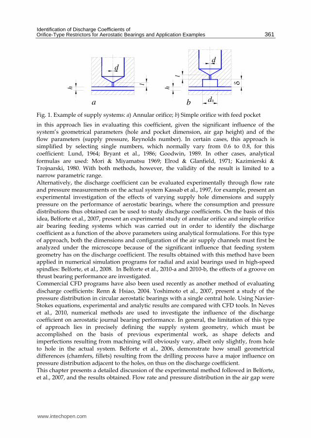
l
hd
a d
l
h
b 0
δ
d
Fig. 1. Example of supply systems: a) Annular orifice; b) Simple orifice with feed pocket
in this approach lies in evaluating this coefficient, given the significant influence of the system’s geometrical parameters (hole and pocket dimension, air gap height) and of the flow parameters (supply pressure, Reynolds number). In certain cases, this approach is simplified by selecting single numbers, which normally vary from 0.6 to 0.8, for this coefficient: Lund, 1964; Bryant et al., 1986; Goodwin, 1989. In other cases, analytical
formulas are used: Mori & Miyamatsu 1969; Elrod & Glanfield, 1971; Kazimierski & Trojnarski, 1980. With both methods, however, the validity of the result is limited to a narrow parametric range. Alternatively, the discharge coefficient can be evaluated experimentally through flow rate and pressure measurements on the actual system Kassab et al., 1997, for example, present an experimental investigation of the effects of varying supply hole dimensions and supply pressure on the performance of aerostatic bearings, where the consumption and pressure distributions thus obtained can be used to study discharge coefficients. On the basis of this idea, Belforte et al., 2007, present an experimental study of annular orifice and simple orifice air bearing feeding systems which was carried out in order to identify the discharge coefficient as a function of the above parameters using analytical formulations. For this type of approach, both the dimensions and configuration of the air supply channels must first be analyzed under the microscope because of the significant influence that feeding system geometry has on the discharge coefficient. The results obtained with this method have been applied in numerical simulation programs for radial and axial bearings used in high-speed spindles: Belforte, et al., 2008. In Belforte et al., 2010-a and 2010-b, the effects of a groove on thrust bearing performance are investigated. Commercial CFD programs have also been used recently as another method of evaluating
discharge coefficients: Renn & Hsiao, 2004. Yoshimoto et al., 2007, present a study of the pressure distribution in circular aerostatic bearings with a single central hole. Using Navier-Stokes equations, experimental and analytic results are compared with CFD tools. In Neves et al., 2010, numerical methods are used to investigate the influence of the discharge coefficient on aerostatic journal bearing performance. In general, the limitation of this type of approach lies in precisely defining the supply system geometry, which must be accomplished on the basis of previous experimental work, as shape defects and imperfections resulting from machining will obviously vary, albeit only slightly, from hole to hole in the actual system. Belforte et al., 2006, demonstrate how small geometrical differences (chamfers, fillets) resulting from the drilling process have a major influence on pressure distribution adjacent to the holes, on thus on the discharge coefficient. This chapter presents a detailed discussion of the experimental method followed in Belforte, et al., 2007, and the results obtained. Flow rate and pressure distribution in the air gap were
www.intechopen.com
New Tribological Ways
362
measured on a number of flat pad bearings for various supply hole and pocket dimensions and bearing supply pressures. The results made it possible to define two formulations for the discharge coefficient where the air flow is considered as passing both through the circular section of the hole and through the annular section between the hole and the air gap. Finite difference models using these formulations were developed specifically for the cases examined. Comparisons are then presented between the pressure distributions obtained experimentally and numerically, both for the pads used for identification and for other similar pads tested previously: Belforte et al., 2010-c. Experimental tests were then carried out to determine that these formulas can also be applied under certain geometrical conditions to feeding systems with grooves.
3. Test bench and pads under test
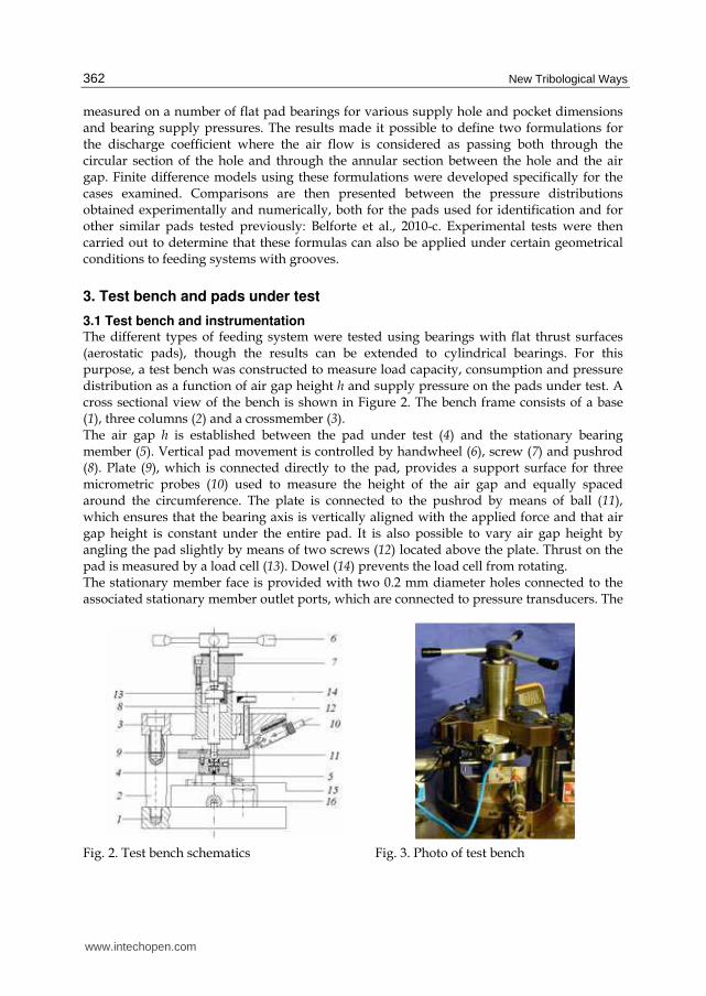
3.1 Test bench and instrumentation The different types of feeding system were tested using bearings with flat thrust surfaces (aerostatic pads), though the results can be extended to cylindrical bearings. For this purpose, a test bench was constructed to measure load capacity, consumption and pressure distribution as a function of air gap height h and supply pressure on the pads under test. A cross sectional view of the bench is shown in Figure 2. The bench frame consists of a base (1), three columns (2) and a crossmember (3). The air gap h is established between the pad under test (4) and the stationary bearing member (5). Vertical pad movement is controlled by handwheel (6), screw (7) and pushrod (8). Plate (9), which is connected directly to the pad, provides a support surface for three micrometric probes (10) used to measure the height of the air gap and equally spaced around the circumference. The plate is connected to the pushrod by means of ball (11), which ensures that the bearing axis is vertically aligned with the applied force and that air gap height is constant under the entire pad. It is also possible to vary air gap height by angling the pad slightly by means of two screws (12) located above the plate. Thrust on the pad is measured by a load cell (13). Dowel (14) prevents the load cell from rotating. The stationary member face is provided with two 0.2 mm diameter holes connected to the associated stationary member outlet ports, which are connected to pressure transducers. The
Fig. 2. Test bench schematics Fig. 3. Photo of test bench
www.intechopen.com
Identification of Discharge Coefficients of Orifice-Type Restrictors for Aerostatic Bearings and Application Examples
363
clip AE 101
z G H / N PW
z G H / N PW
24 Vdc- +
z G H / N PW
12 Vdc
- +
DX BX
C
210
0
17
1819
2021
2223
24 2526
27 28 29 30
31
32 33
34
35
36
37
38
39
40
41
42
43
44
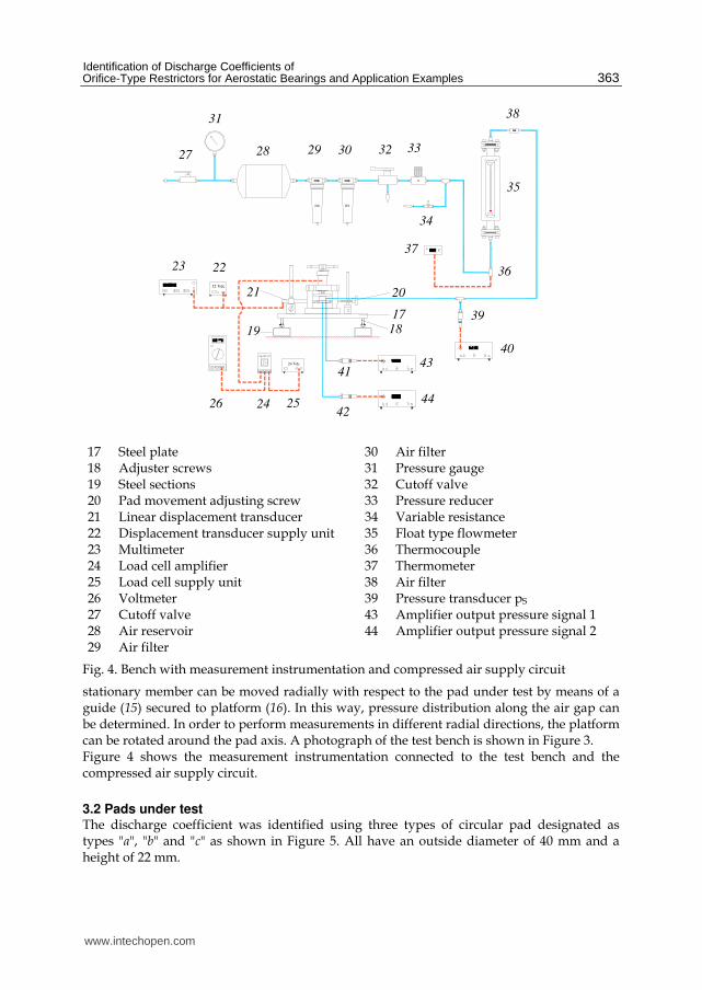
17 Steel plate 30 Air filter 18 Adjuster screws 31 Pressure gauge 19 Steel sections 32 Cutoff valve 20 Pad movement adjusting screw 33 Pressure reducer 21 Linear displacement transducer 34 Variable resistance 22 Displacement transducer supply unit 35 Float type flowmeter 23 Multimeter 36 Thermocouple 24 Load cell amplifier 37 Thermometer 25 Load cell supply unit 38 Air filter 26 Voltmeter 39 Pressure transducer pS
27 Cutoff valve 43 Amplifier output pressure signal 1 28 Air reservoir 44 Amplifier output pressure signal 2 29 Air filter
Fig. 4. Bench with measurement instrumentation and compressed air supply circuit
stationary member can be moved radially with respect to the pad under test by means of a guide (15) secured to platform (16). In this way, pressure distribution along the air gap can be determined. In order to perform measurements in different radial directions, the platform can be rotated around the pad axis. A photograph of the test bench is shown in Figure 3. Figure 4 shows the measurement instrumentation connected to the test bench and the compressed air supply circuit.
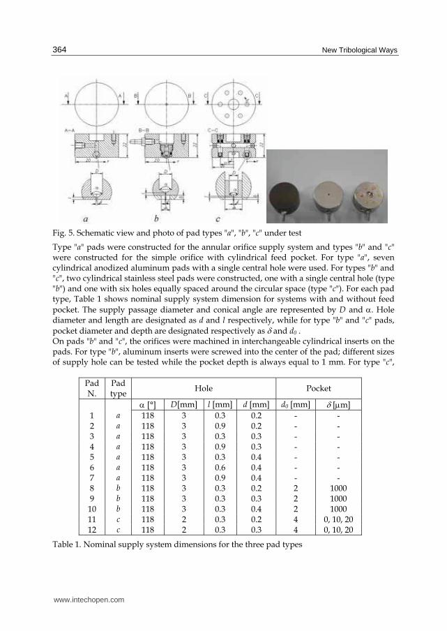
3.2 Pads under test The discharge coefficient was identified using three types of circular pad designated as types "a", "b" and "c" as shown in Figure 5. All have an outside diameter of 40 mm and a height of 22 mm.
www.intechopen.com
New Tribological Ways
364
Fig. 5. Schematic view and photo of pad types "a", "b", "c" under test
Type "a" pads were constructed for the annular orifice supply system and types "b" and "c" were constructed for the simple orifice with cylindrical feed pocket. For type "a", seven cylindrical anodized aluminum pads with a single central hole were used. For types "b" and "c", two cylindrical stainless steel pads were constructed, one with a single central hole (type "b") and one with six holes equally spaced around the circular space (type "c"). For each pad type, Table 1 shows nominal supply system dimension for systems with and without feed
pocket. The supply passage diameter and conical angle are represented by D and α. Hole diameter and length are designated as d and l respectively, while for type "b" and "c" pads,
pocket diameter and depth are designated respectively as δ and d0 . On pads "b" and "c", the orifices were machined in interchangeable cylindrical inserts on the pads. For type "b", aluminum inserts were screwed into the center of the pad; different sizes of supply hole can be tested while the pocket depth is always equal to 1 mm. For type "c",
Pad N.
Pad type
Hole Pocket
α [°] D[mm] l [mm] d [mm] d0 [mm] δ [μm]
1 a 118 3 0.3 0.2 - - 2 a 118 3 0.9 0.2 - - 3 a 118 3 0.3 0.3 - - 4 a 118 3 0.9 0.3 - - 5 a 118 3 0.3 0.4 - - 6 a 118 3 0.6 0.4 - - 7 a 118 3 0.9 0.4 - - 8 b 118 3 0.3 0.2 2 1000 9 b 118 3 0.3 0.3 2 1000 10 b 118 3 0.3 0.4 2 1000 11 c 118 2 0.3 0.2 4 0, 10, 20 12 c 118 2 0.3 0.3 4 0, 10, 20
Table 1. Nominal supply system dimensions for the three pad types
www.intechopen.com
Identification of Discharge Coefficients of Orifice-Type Restrictors for Aerostatic Bearings and Application Examples
365
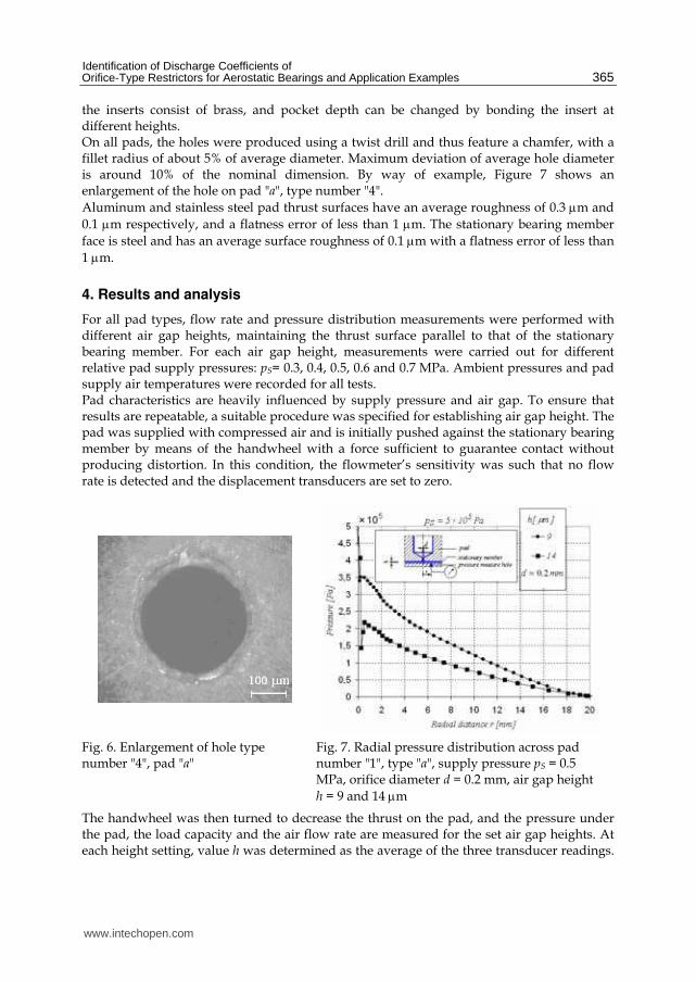
the inserts consist of brass, and pocket depth can be changed by bonding the insert at different heights. On all pads, the holes were produced using a twist drill and thus feature a chamfer, with a fillet radius of about 5% of average diameter. Maximum deviation of average hole diameter is around 10% of the nominal dimension. By way of example, Figure 7 shows an enlargement of the hole on pad "a", type number "4".
Aluminum and stainless steel pad thrust surfaces have an average roughness of 0.3 μm and
0.1 μm respectively, and a flatness error of less than 1 μm. The stationary bearing member
face is steel and has an average surface roughness of 0.1 μm with a flatness error of less than
1 μm.
4. Results and analysis
For all pad types, flow rate and pressure distribution measurements were performed with different air gap heights, maintaining the thrust surface parallel to that of the stationary bearing member. For each air gap height, measurements were carried out for different relative pad supply pressures: pS= 0.3, 0.4, 0.5, 0.6 and 0.7 MPa. Ambient pressures and pad supply air temperatures were recorded for all tests. Pad characteristics are heavily influenced by supply pressure and air gap. To ensure that results are repeatable, a suitable procedure was specified for establishing air gap height. The pad was supplied with compressed air and is initially pushed against the stationary bearing member by means of the handwheel with a force sufficient to guarantee contact without producing distortion. In this condition, the flowmeter’s sensitivity was such that no flow rate is detected and the displacement transducers are set to zero.
Fig. 6. Enlargement of hole type number "4", pad "a"
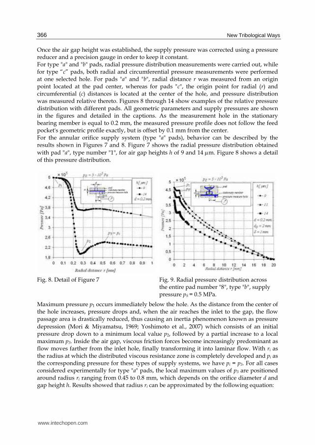
Fig. 7. Radial pressure distribution across pad number "1", type "a", supply pressure pS = 0.5 MPa, orifice diameter d = 0.2 mm, air gap height
h = 9 and 14 μm
The handwheel was then turned to decrease the thrust on the pad, and the pressure under the pad, the load capacity and the air flow rate are measured for the set air gap heights. At each height setting, value h was determined as the average of the three transducer readings.
www.intechopen.com
New Tribological Ways
366
Once the air gap height was established, the supply pressure was corrected using a pressure reducer and a precision gauge in order to keep it constant. For type "a" and "b" pads, radial pressure distribution measurements were carried out, while for type “c” pads, both radial and circumferential pressure measurements were performed at one selected hole. For pads "a" and "b", radial distance r was measured from an origin point located at the pad center, whereas for pads "c", the origin point for radial (r) and circumferential (c) distances is located at the center of the hole, and pressure distribution was measured relative thereto. Figures 8 through 14 show examples of the relative pressure distribution with different pads. All geometric parameters and supply pressures are shown in the figures and detailed in the captions. As the measurement hole in the stationary bearing member is equal to 0.2 mm, the measured pressure profile does not follow the feed pocket's geometric profile exactly, but is offset by 0.1 mm from the center. For the annular orifice supply system (type "a" pads), behavior can be described by the results shown in Figures 7 and 8. Figure 7 shows the radial pressure distribution obtained
with pad "a", type number "1", for air gap heights h of 9 and 14 μm. Figure 8 shows a detail of this pressure distribution.
Fig. 8. Detail of Figure 7
Fig. 9. Radial pressure distribution across the entire pad number "8", type "b", supply pressure pS = 0.5 MPa.
Maximum pressure p1 occurs immediately below the hole. As the distance from the center of the hole increases, pressure drops and, when the air reaches the inlet to the gap, the flow passage area is drastically reduced, thus causing an inertia phenomenon known as pressure
depression (Mori & Miyamatsu, 1969; Yoshimoto et al., 2007) which consists of an initial pressure drop down to a minimum local value p2, followed by a partial increase to a local maximum p3. Inside the air gap, viscous friction forces become increasingly predominant as flow moves farther from the inlet hole, finally transforming it into laminar flow. With ri as the radius at which the distributed viscous resistance zone is completely developed and pi as the corresponding pressure for these types of supply systems, we have pi = p3. For all cases considered experimentally for type "a" pads, the local maximum values of p3 are positioned around radius ri ranging from 0.45 to 0.8 mm, which depends on the orifice diameter d and gap height h. Results showed that radius ri can be approximated by the following equation:
www.intechopen.com
Identification of Discharge Coefficients of Orifice-Type Restrictors for Aerostatic Bearings and Application Examples
367
402
i
dr h= + (2)
For simple orifices with feed pocket (type "b" and "c" pads), behavior can be described by the results shown in Figures 9 through 13.
For pads with very deep pockets (type "b", δ = 1 mm), a good example of radial pressure distribution is shown in Figure 9 for pad "8". Supply pressure pS is to 0.5 MPa, and the
curves refer to air gap heights h of 9, 11 and 14 μm. A detail of the pressure distribution in the area adjacent to the supply orifice is shown in Figure 10.
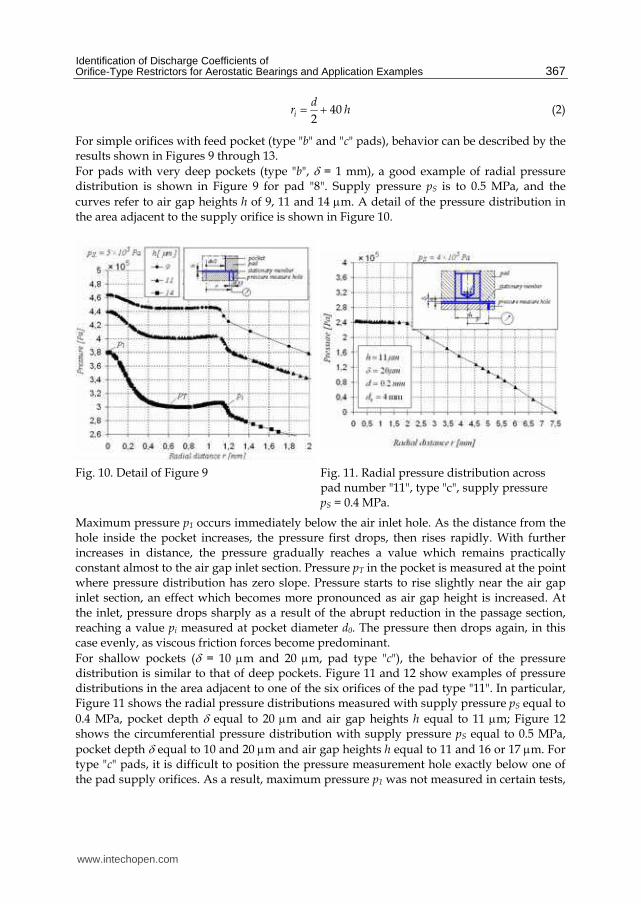
Fig. 10. Detail of Figure 9 Fig. 11. Radial pressure distribution across pad number "11", type "c", supply pressure pS = 0.4 MPa.
Maximum pressure p1 occurs immediately below the air inlet hole. As the distance from the hole inside the pocket increases, the pressure first drops, then rises rapidly. With further increases in distance, the pressure gradually reaches a value which remains practically constant almost to the air gap inlet section. Pressure pT in the pocket is measured at the point where pressure distribution has zero slope. Pressure starts to rise slightly near the air gap inlet section, an effect which becomes more pronounced as air gap height is increased. At the inlet, pressure drops sharply as a result of the abrupt reduction in the passage section, reaching a value pi measured at pocket diameter d0. The pressure then drops again, in this case evenly, as viscous friction forces become predominant.
For shallow pockets (δ = 10 μm and 20 μm, pad type "c"), the behavior of the pressure distribution is similar to that of deep pockets. Figure 11 and 12 show examples of pressure distributions in the area adjacent to one of the six orifices of the pad type "11". In particular, Figure 11 shows the radial pressure distributions measured with supply pressure pS equal to
0.4 MPa, pocket depth δ equal to 20 μm and air gap heights h equal to 11 μm; Figure 12 shows the circumferential pressure distribution with supply pressure pS equal to 0.5 MPa,
pocket depth δ equal to 10 and 20 μm and air gap heights h equal to 11 and 16 or 17 μm. For type "c" pads, it is difficult to position the pressure measurement hole exactly below one of the pad supply orifices. As a result, maximum pressure p1 was not measured in certain tests,
www.intechopen.com
New Tribological Ways
368
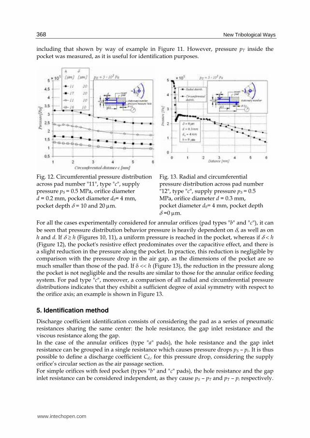
including that shown by way of example in Figure 11. However, pressure pT inside the pocket was measured, as it is useful for identification purposes.
Fig. 12. Circumferential pressure distribution across pad number "11", type "c", supply pressure pS = 0.5 MPa, orifice diameter d = 0.2 mm, pocket diameter d0= 4 mm,
pocket depth δ = 10 and 20 μm.
Fig. 13. Radial and circumferential pressure distribution across pad number "12", type "c", supply pressure pS = 0.5 MPa, orifice diameter d = 0.3 mm, pocket diameter d0= 4 mm, pocket depth δ =0 μm.
For all the cases experimentally considered for annular orifices (pad types "b" and "c"), it can
be seen that pressure distribution behavior pressure is heavily dependent on δ, as well as on h and d. If δ ≥ h (Figures 10, 11), a uniform pressure is reached in the pocket, whereas if δ < h (Figure 12), the pocket's resistive effect predominates over the capacitive effect, and there is a slight reduction in the pressure along the pocket. In practice, this reduction is negligible by comparison with the pressure drop in the air gap, as the dimensions of the pocket are so much smaller than those of the pad. If δ << h (Figure 13), the reduction in the pressure along the pocket is not negligible and the results are similar to those for the annular orifice feeding system. For pad type "c", moreover, a comparison of all radial and circumferential pressure distributions indicates that they exhibit a sufficient degree of axial symmetry with respect to the orifice axis; an example is shown in Figure 13.
5. Identification method
Discharge coefficient identification consists of considering the pad as a series of pneumatic resistances sharing the same center: the hole resistance, the gap inlet resistance and the viscous resistance along the gap. In the case of the annular orifices (type "a" pads), the hole resistance and the gap inlet resistance can be grouped in a single resistance which causes pressure drops pS – pi. It is thus possible to define a discharge coefficient Cd,c for this pressure drop, considering the supply orifice’s circular section as the air passage section. For simple orifices with feed pocket (types "b" and "c" pads), the hole resistance and the gap inlet resistance can be considered independent, as they cause pS – pT and pT – pi respectively.
www.intechopen.com
Identification of Discharge Coefficients of Orifice-Type Restrictors for Aerostatic Bearings and Application Examples
369
Two discharge coefficients can thus be defined, one for each of the two localized pressure drops. As for annular orifice systems, discharge coefficient Cd,c for the first pressure drop pS – pT is calculated considering the supply orifice's circular section of diameter d as the air passage section. Discharge coefficient Cd,a for the second pressure drop pT – pi is calculated by taking the annular section of height h and diameter d0 as the passage section. When the
pocket is sufficiently deep ( δ > 20 μm), the pressure drop at the air gap inlet is significant by comparison with that across the inlet hole, and in this case both the discharge coefficients
must be defined. In all cases with δ ≤ 20 μm, pT ≅ pi and it is possible to define only coefficient Cd,c. The theoretical air flow rate through each lumped resistance is given by equation (3):
2 1
2
1
2 if 0.528
1
2 2 if 0.528
1 1
k
k kd d d
t uu u u
k dt u
u
P P PkG S P
k P P R T P
PkG S P
k k R T P
+
−
⎡ ⎤⎛ ⎞ ⎛ ⎞⎢ ⎥= ⋅ − ⋅ ≥⎜ ⎟ ⎜ ⎟⎢ ⎥− ⋅⎝ ⎠ ⎝ ⎠⎢ ⎥⎣ ⎦⎛ ⎞ ⎛ ⎞= ⋅ ⋅ ⋅ <⎜ ⎟ ⎜ ⎟+ + ⋅⎝ ⎠ ⎝ ⎠
(3)
where Pu and Pd are the resistances' upstream and downstream absolute pressures, T is the absolute temperature upstream of the nozzle, S is the passage section area, R = 287.1 J/(kg K) is the air constant, and k = 1.4 is the specific heat ratio of air at constant pressure and volume. As Gt and G are known, the values of Cd,c and Cd,a were calculated using equation (1). In order to allow for the effect of geometric parameters and flow conditions on system operation, Cd,c and Cd,a can be defined as a function of the Reynolds number Re. Considering the characteristic dimension to be diameter d for the circular passage section, and height h for the annular passage section, the Reynolds numbers for the two sections are respectively:
4
Rec
┩ u d G
μ ┨ d μ= = ;
0
Rea
┩ u h G
μ ┨ d μ= = (4)
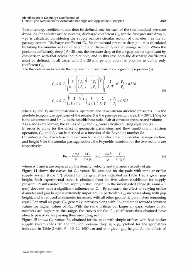
where ρ, u and μ are respectively the density, velocity and dynamic viscosity of air. Figure 14 shows the curves for Cd,c versus Rec obtained for the pads with annular orifice
supply system (type "a") plotted for the geometries indicated in Table 1 at a given gap
height. Each experimental curve is obtained from the five values established for supply
pressure. Results indicate that supply orifice length l in the investigated range (0.3 mm – 1
mm) does not have a significant influence on Cd,c. By contrast, the effect of varying orifice
diameter and gap height is extremely important. In particular, Cd,c increases along with gap
height, and is reduced as diameter increases, with all other geometric parameters remaining
equal. For small air gaps, Cd,c generally increases along with Rec, and tends towards constant
values for higher values of Rec. With the same orifices but larger air gaps, values of Rec
numbers are higher: in this range, the curves for the Cd,c coefficients thus obtained have
already passed or are passing their ascending section.
Figure 15 shows Cd,c versus Rec obtained for the pads with simple orifices with feed pocket supply system (pads "b" and "c") for pressure drop pS – pT, plotted for the geometries
indicated in Table 2 with δ = 10, 20, 1000 μm and at a given gap height. As the effects of
www.intechopen.com
New Tribological Ways
370
varying orifice length were found to be negligible, tests with feed pocket supply system were carried out only on pads with l = equal to 0.3 mm. The values for Cd,c obtained with the simple orifices with feed pocket are greater than the corresponding coefficients obtained with annular orifice system, but the trend with Rec is similar. In particular, the same results
shown in Figure 14 are obtained if δ tends to zero.
If δ = 10, 20 μm Cd,c is heavily dependent on h, d, δ: it increases along with gap height h and δ, and is reduced as diameter d increases, with all other geometric parameters remaining equal.
If δ = 1 mm, values for Cd,c do not vary appreciably with system geometry, but depend
significantly only on Rec. For Rec → ∞, the curves tend toward limits that assume average values close to Cd,c max= 0.85.
Fig. 14. Experimental values for Cd,c versus Rec obtained for type "a" pads
Fig. 15. Experimental values for Cd,c versus Rec obtained for type "b" and "c" pads, and with l = 0.3 mm
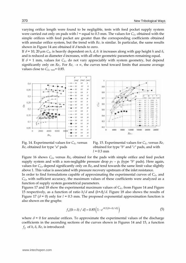
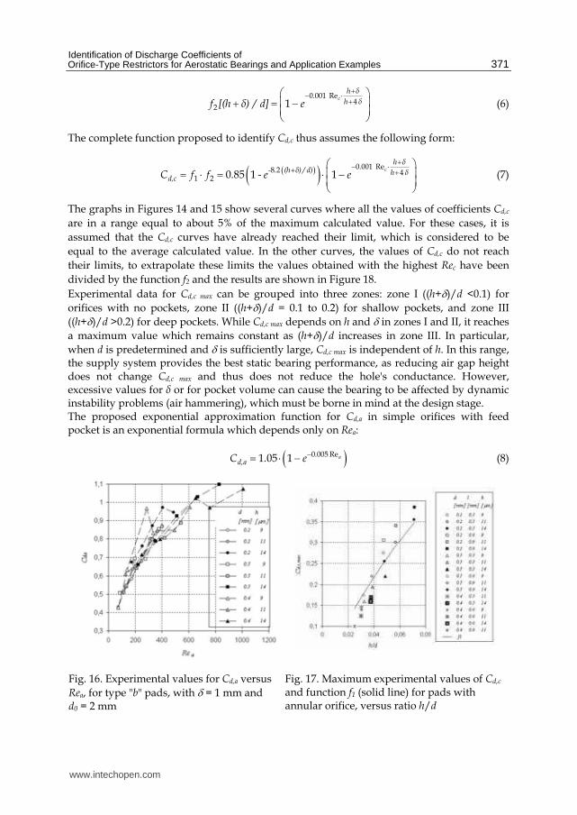
Figure 16 shows Cd,a versus Rea obtained for the pads with simple orifice and feed pocket supply system and with a non-negligible pressure drop pT – pi (type "b" pads). Here again, values for Cd,a depend significantly only on Rea and tend towards the same limit value slightly above 1. This value is associated with pressure recovery upstream of the inlet resistance. In order to find formulations capable of approximating the experimental curves of Cd,c and Cd,a with sufficient accuracy, the maximum values of these coefficients were analyzed as a function of supply system geometrical parameters. Figures 17 and 18 show the experimental maximum values of Cd,c from Figure 14 and Figure
15 respectively, as a function of ratio h/d and (h+δ)/d. Figure 18 also shows the results of
Figure 17 (δ = 0) only for l = 0.3 mm. The proposed exponential approximation function is also shown on the graphs:
( )( )8 21 0 85 1
- . (h δ) / d)f [(h δ) / d] . - e
++ = (5)
where δ = 0 for annular orifices. To approximate the experimental values of the discharge coefficients in the ascending sections of the curves shown in Figures 14 and 15, a function
2f of h, δ, Rec is introduced:
www.intechopen.com
Identification of Discharge Coefficients of Orifice-Type Restrictors for Aerostatic Bearings and Application Examples
371
0 001 Re
42 1
ch δ
. h δf [(h δ) / d] e
+− ⋅ +⎛ ⎞⎜ ⎟+ = −⎜ ⎟⎝ ⎠ (6)
The complete function proposed to identify Cd,c thus assumes the following form:
( )( ) 0 001 Re8 2 41 2 0 85 1 1
ch δ
. - . (h δ) / d) h δd,cC f f . - e e
+− ⋅+ +⎛ ⎞⎜ ⎟= ⋅ = ⋅ −⎜ ⎟⎝ ⎠ (7)
The graphs in Figures 14 and 15 show several curves where all the values of coefficients Cd,c
are in a range equal to about 5% of the maximum calculated value. For these cases, it is
assumed that the Cd,c curves have already reached their limit, which is considered to be
equal to the average calculated value. In the other curves, the values of Cd,c do not reach
their limits, to extrapolate these limits the values obtained with the highest Rec have been
divided by the function f2 and the results are shown in Figure 18.
Experimental data for Cd,c max can be grouped into three zones: zone I ((h+δ)/d <0.1) for
orifices with no pockets, zone II ((h+δ)/d = 0.1 to 0.2) for shallow pockets, and zone III
((h+δ)/d >0.2) for deep pockets. While Cd,c max depends on h and δ in zones I and II, it reaches
a maximum value which remains constant as (h+δ)/d increases in zone III. In particular,
when d is predetermined and δ is sufficiently large, Cd,c max is independent of h. In this range, the supply system provides the best static bearing performance, as reducing air gap height does not change Cd,c max and thus does not reduce the hole's conductance. However, excessive values for δ or for pocket volume can cause the bearing to be affected by dynamic instability problems (air hammering), which must be borne in mind at the design stage. The proposed exponential approximation function for Cd,a in simple orifices with feed pocket is an exponential formula which depends only on Rea:
( )0 005 Re1 05 1 a. d,aC . e−= ⋅ − (8)
Fig. 16. Experimental values for Cd,a versus
Rea, for type "b" pads, with δ = 1 mm and d0 = 2 mm
Fig. 17. Maximum experimental values of Cd,c and function f1 (solid line) for pads with annular orifice, versus ratio h/d
www.intechopen.com
New Tribological Ways
372
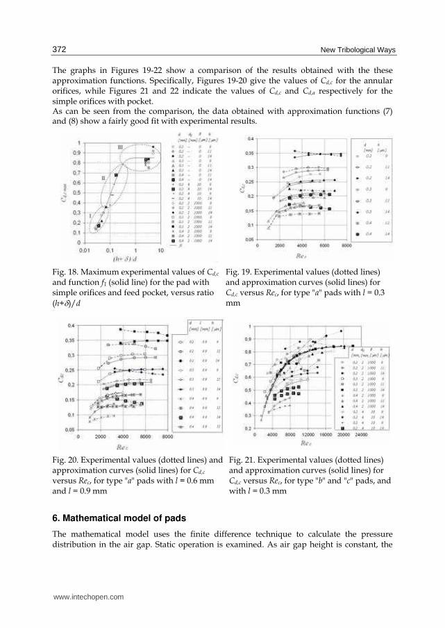
The graphs in Figures 19-22 show a comparison of the results obtained with the these approximation functions. Specifically, Figures 19-20 give the values of Cd,c for the annular orifices, while Figures 21 and 22 indicate the values of Cd,c and Cd,a respectively for the simple orifices with pocket. As can be seen from the comparison, the data obtained with approximation functions (7) and (8) show a fairly good fit with experimental results.
Fig. 18. Maximum experimental values of Cd,c and function f1 (solid line) for the pad with simple orifices and feed pocket, versus ratio
(h+δ)/d
Fig. 19. Experimental values (dotted lines) and approximation curves (solid lines) for Cd,c versus Rec, for type "a" pads with l = 0.3 mm
Fig. 20. Experimental values (dotted lines) and approximation curves (solid lines) for Cd,c versus Rec, for type "a" pads with l = 0.6 mm and l = 0.9 mm
Fig. 21. Experimental values (dotted lines) and approximation curves (solid lines) for Cd,c versus Rec, for type "b" and "c" pads, and with l = 0.3 mm
6. Mathematical model of pads
The mathematical model uses the finite difference technique to calculate the pressure distribution in the air gap. Static operation is examined. As air gap height is constant, the
www.intechopen.com
Identification of Discharge Coefficients of Orifice-Type Restrictors for Aerostatic Bearings and Application Examples
373
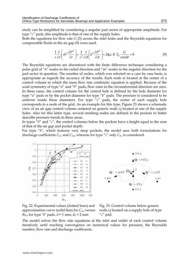
study can be simplified by considering a angular pad sector of appropriate amplitude. For type “c” pads, this amplitude is that of one of the supply holes. Both the equations for flow rate G (3) across the inlet holes and the Reynolds equations for compressible fluids in the air gap (9) were used.
2 2
3 302
1 124 0
P P Grh h R T
r r r rdrdrμϑ ϑ ϑ
⎛ ⎞ ⎛ ⎞∂ ∂ ∂ ∂+ + =⎜ ⎟ ⎜ ⎟⎜ ⎟ ⎜ ⎟∂ ∂ ∂ ∂⎝ ⎠ ⎝ ⎠ (9)
The Reynolds equations are discretized with the finite difference technique considering a polar grid of “n” nodes in the radial direction and “m” nodes in the angular direction for the pad sector in question. The number of nodes, which was selected on a case by case basis, is appropriate as regards the accuracy of the results. Each node is located at the center of a control volume to which the mass flow rate continuity equation is applied. Because of the axial symmetry of type “a” and “b” pads, flow rates in the circumferential direction are zero. In these cases, the control volume for the central hole is defined by the hole diameter for type “a” pads or by the pocket diameter for type “b” pads. The pressure is considered to be uniform inside these diameters. For type “c” pads, the center of each supply hole corresponds to a node of the grid. As an example for this type, Figure 23 shows a schematic view of an air gap control volume centered on generic node i,j located at one of the supply holes. Also for this latter type, several meshing nodes are defined in the pockets to better describe pressure trends in these areas. In types “b” and “c”, the control volumes below the pockets have a height equal to the sum of that of the air gap and pocket depth. For type “b”, which features very deep pockets, the model uses both formulations for discharge coefficients Cd,c and Cd,a, whereas for type “c” only Cd,c is considered.
qr i -1/2, j
Gijq i , j+1/2
i, j+1
i-1, j
q i , j-1/2i, j
i, j-1
qr i +1/2, j
i+1, j
Fig. 22. Experimental values (dotted lines) and approximation curve (solid line) for Cd,a versus
Rea, for type "b" pads, δ = 1 mm, d0 = 2 mm
Fig. 23. Control volume below generic node i,j located on a supply hole of type “c” pad.
The model solves the flow rate equations at the inlet and outlet of each control volume iteratively until reaching convergence on numerical values for pressure, the Reynolds number, flow rate and discharge coefficients.
www.intechopen.com
New Tribological Ways
374
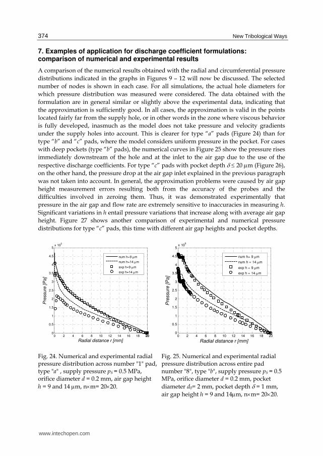
7. Examples of application for discharge coefficient formulations: comparison of numerical and experimental results
A comparison of the numerical results obtained with the radial and circumferential pressure
distributions indicated in the graphs in Figures 9 – 12 will now be discussed. The selected
number of nodes is shown in each case. For all simulations, the actual hole diameters for
which pressure distribution was measured were considered. The data obtained with the
formulation are in general similar or slightly above the experimental data, indicating that
the approximation is sufficiently good. In all cases, the approximation is valid in the points
located fairly far from the supply hole, or in other words in the zone where viscous behavior
is fully developed, inasmuch as the model does not take pressure and velocity gradients
under the supply holes into account. This is clearer for type “a” pads (Figure 24) than for
type “b” and “c” pads, where the model considers uniform pressure in the pocket. For cases
with deep pockets (type “b” pads), the numerical curves in Figure 25 show the pressure rises
immediately downstream of the hole and at the inlet to the air gap due to the use of the
respective discharge coefficients. For type “c” pads with pocket depth δ ≤ 20 μm (Figure 26),
on the other hand, the pressure drop at the air gap inlet explained in the previous paragraph
was not taken into account. In general, the approximation problems were caused by air gap
height measurement errors resulting both from the accuracy of the probes and the
difficulties involved in zeroing them. Thus, it was demonstrated experimentally that
pressure in the air gap and flow rate are extremely sensitive to inaccuracies in measuring h.
Significant variations in h entail pressure variations that increase along with average air gap
height. Figure 27 shows another comparison of experimental and numerical pressure
distributions for type “c” pads, this time with different air gap heights and pocket depths.
0 2 4 6 8 10 12 14 16 18 20200
0.5
1
1.5
2
2.5
3
3.5
4
4.5
5x 10
5
Radial distance r [mm]
Pre
ssure
[P
a]
num h=9 μm
num h=14 μm
exp h=9 μm
exp h=14 μm
0 2 4 6 8 10 12 14 16 18 200
0.5
1
1.5
2
2.5
3
3.5
4
4.5
5x 10
5
Radial distance r [mm]
Pre
ssure
[P
a]
num h= 9 μm
num h = 14 μm
exp h = 9 μm
exp h = 14 μm
Fig. 24. Numerical and experimental radial pressure distribution across number "1" pad, type "a" , supply pressure pS = 0.5 MPa, orifice diameter d = 0.2 mm, air gap height
h = 9 and 14 μm, n×m= 20×20.
Fig. 25. Numerical and experimental radial pressure distribution across entire pad number "8", type "b", supply pressure pS = 0.5 MPa, orifice diameter d = 0.2 mm, pocket
diameter d0= 2 mm, pocket depth δ = 1 mm,
air gap height h = 9 and 14μm, n×m= 20×20.
www.intechopen.com
Identification of Discharge Coefficients of Orifice-Type Restrictors for Aerostatic Bearings and Application Examples
375
0 0.5 1 1.5 2 2.5 3 3.5 4 4.5 5 5.5 6 6.5 7 7.50
0.5
1
1.5
2
2.5
3
3.5
4x 10
5
Radial distance r [mm]
Pre
ssure
[P
a]
num h = 11 μm
exp h = 11 μm
0 1 2 3 4 5 6
0
0.5
1
1.5
2
2.5
3
3.5
4
4.5
5x 10
5
Circumferential distance c [mm]
Pre
ssu
re [P
a]
num h=11 μm, δ=20 μm
exp h=11 μm, δ=20 μm
num h=17 μm, δ=20 μm
exp h=17 μm, δ=20 μm
num h=11 μm, δ=10 μm
exp h=11 μm, δ=10 μm
num h=16 μm, δ=10 μm
exp h=16 μm, δ=10 μm
Fig. 26. Radial pressure distribution across pad number "11", type "c", supply pressure pS = 0.4 MPa, orifice diameter d = 0.2 mm, pocket
diameter d0= 4 mm, pocket depth δ = 20 μm, air
gap height h = 11 μm , n×m= 20×20.
Fig. 27. Numerical and experimental circumferential pressure distribution across pad number "11", type "c", supply pressure pS = 0.5 MPa, orifice diameter d = 0.2 mm, pocket diameter d0 = 4 mm, pocket depth δ = 10 and 20 μm, n×m= 20×20.
Fig. 28. Further pads tested to verify the discharge coefficient formulation
The discharge coefficient formulation was also verified experimentally on a further three pads as shown in the diagram and photograph in Figure 28, including two type “c” pads and one grooved pad (type “d”). Table 3 shows the nominal geometric magnitudes for each pad. The first two (13, 14) have a different number of holes and pocket depth is zero. The third (15) features 10 µm deep pockets and a circular groove connecting the supply holes. The groove is 0.8 mm wide and its depth is equal to that of the pockets. The figure also shows an enlargement of the insert and groove for pad 15 and the groove profile as measured radially using a profilometer. In these three cases, the center of the pads was selected as the origin point for radial coordinate r and the center of one of the supply holes was chosen as the origin point of angular coordinate ϑ.
www.intechopen.com
New Tribological Ways
376
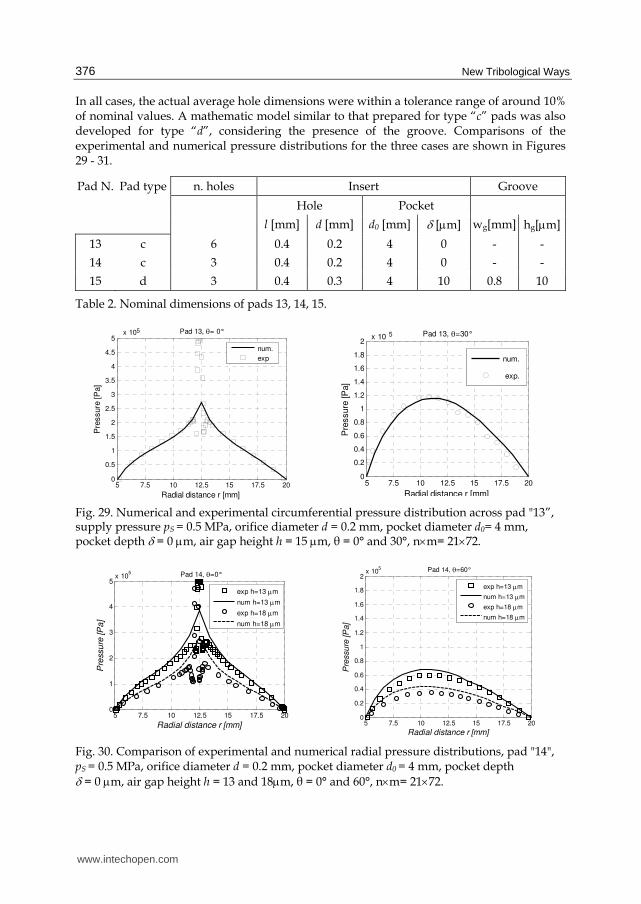
In all cases, the actual average hole dimensions were within a tolerance range of around 10% of nominal values. A mathematic model similar to that prepared for type “c” pads was also developed for type “d”, considering the presence of the groove. Comparisons of the experimental and numerical pressure distributions for the three cases are shown in Figures 29 - 31.
Pad N. Pad type n. holes Insert Groove
Hole Pocket
l [mm] d [mm] d0 [mm] δ [μm] wg[mm] hg[μm]
13 c 6 0.4 0.2 4 0 - -
14 c 3 0.4 0.2 4 0 - -
15 d 3 0.4 0.3 4 10 0.8 10
Table 2. Nominal dimensions of pads 13, 14, 15.
5 7.5 10 12.5 15 17.5 200
0.5
1
1.5
2
2.5
3
3.5
4
4.5
5
Radial distance r [mm]
Pre
ssure
[P
a]
Pad 13, θ= 0°
num.
exp
x 105
5 7.5 10 12.5 15 17.5 20
0
0.2
0.4
0.6
0.8
1
1.2
1.4
1.6
1.8
2
Radial distance r [mm]
Pre
ssure
[P
a]
Pad 13, θ=30°
num.
exp.
x 10 5
Fig. 29. Numerical and experimental circumferential pressure distribution across pad "13”, supply pressure pS = 0.5 MPa, orifice diameter d = 0.2 mm, pocket diameter d0= 4 mm, pocket depth δ = 0 μm, air gap height h = 15 μm, θ = 0° and 30°, n×m= 21×72.
5 7.5 10 12.5 15 17.5 200
1
2
3
4
5x 10
5
Radial distance r [mm]
Pre
ssu
re [P
a]
Pad 14, θ=0°
exp h=13 μm
num h=13 μm
exp h=18 μm
num h=18 μm
5 7.5 10 12.5 15 17.5 20
0
0.2
0.4
0.6
0.8
1
1.2
1.4
1.6
1.8
2x 10
5
Radial distance r [mm]
Pre
ssu
re [P
a]
Pad 14, θ=60°
exp h=13 μm
num h=13 μm
exp h=18 μm
num h=18 μm
Fig. 30. Comparison of experimental and numerical radial pressure distributions, pad "14", pS = 0.5 MPa, orifice diameter d = 0.2 mm, pocket diameter d0 = 4 mm, pocket depth δ = 0 μm, air gap height h = 13 and 18μm, θ = 0° and 60°, n×m= 21×72.
www.intechopen.com
Identification of Discharge Coefficients of Orifice-Type Restrictors for Aerostatic Bearings and Application Examples
377
5 7.5 10 12.5 15 17.5 200
1
2
3
4
5x 10
5
Radial distance r [mm]
Pre
ssu
re [P
a]
Pad 15, θ=0°
exp h=13 μm
num h=13 μm
exp h=18 μm
num h=18 μm
5 7.5 10 12.5 15 17.5 200
0.2
0.4
0.6
0.8
1
1.2
1.4
1.6
1.8
2x 10
5
Radial distance r [mm]
Pre
ssure
[P
a]
Pad 15, θ=60°
exp h=13 μm
num h=13 μm
exp h=18 μm
num h=18 μm
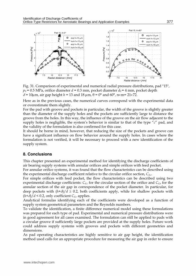
Fig. 31. Comparison of experimental and numerical radial pressure distributions, pad "15", pS = 0.5 MPa, orifice diameter d = 0.3 mm, pocket diameter d0 = 4 mm, pocket depth δ = 10μm, air gap height h = 13 and 18 μm, θ = 0° and 60°, n×m= 21×72.
Here as in the previous cases, the numerical curves correspond with the experimental data or overestimate them slightly. For the pad with groove and pockets in particular, the width of the groove is slightly greater than the diameter of the supply holes and the pockets are sufficiently large to distance the groove from the holes. In this way, the influence of the groove on the air flow adjacent to the supply holes is negligible, the system’s behavior is similar to that of the type “c” pad, and the validity of the formulation is also confirmed for this case. It should be borne in mind, however, that reducing the size of the pockets and groove can have a significant influence on flow behavior around the supply holes. In cases where the formulation is not verified, it will be necessary to proceed with a new identification of the supply system.
8. Conclusions
This chapter presented an experimental method for identifying the discharge coefficients of air bearing supply systems with annular orifices and simple orifices with feed pocket. For annular orifice systems, it was found that the flow characteristics can be described using the experimental discharge coefficient relative to the circular orifice section, Cd,c. For simple orifices with feed pocket, the flow characteristics can be described using two experimental discharge coefficients: Cd,c for the circular section of the orifice and Cd,a for the annular section of the air gap in correspondence of the pocket diameter. In particular, for deep pockets with (h+δ)/d ≥ 0.2, both coefficients apply, while for shallow pockets with (h+δ)/d < 0.2, only coefficient Cd,c applies. Analytical formulas identifying each of the coefficients were developed as a function of supply system geometrical parameters and the Reynolds numbers. To validate the identification, a finite difference numerical model using these formulations was prepared for each type of pad. Experimental and numerical pressure distributions were in good agreement for all cases examined. The formulation can still be applied to pads with a circular groove if sufficiently large pockets are provided at the supply holes. Future work could address supply systems with grooves and pockets with different geometries and dimensions. As pad operating characteristics are highly sensitive to air gap height, the identification method used calls for an appropriate procedure for measuring the air gap in order to ensure
www.intechopen.com
New Tribological Ways
378
the necessary accuracy. The method also requires detailed measurement of the pressure distribution adjacent to the supply hole to identify the local maximum pi. Alternative identification methods are now being investigated in order to overcome the difficulties involved in performing these measurements, and preliminary findings are discussed in Belforte et al., 2010-d.
In general, the proposed formulation is applicable for values of ratio (h+δ)/d varying from 0.03 to 5. Further developments will address the identification of annular orifice supply systems with ratio h/d under 0.03.
9. Nomenclature
Cd Discharge coefficient dr Generic control volume radial length
Cd,a Discharge coefficient for annular section
dϑ Generic control volume angular width
Cd,c Discharge coefficient for circular section
k Specific heat ratio of air (= 1.4)
D Supply passage diameter h Air gap height G Mass flow rate l Supply orifice length
Gt Theoretical mass flow rate qr Mass flow rate across control volume in the radial direction
P Absolute pressure qϑ Mass flow rate across control volume in the circumferential direction
Pd Downstream absolute pressure r Radial coordinate
Pu Upstream absolute pressure ri Radius of completely developed viscous resistance zone
R Constant of gas (= 287.1 J/kg K) pi Relative pressure at radius ri Rea Reynolds Number for annular section pT Pocket relative pressure Rec Reynolds Number for circular section pS Supply relative pressure S Passage section u Air velocity
T Absolute temperature upstream of the nozzle
α Conicity angle
T0 Absolute temperature in normal condition ( 288 K)
δ Pocket depth
c Circumferential coordinate μ Air viscosity in normal condition (= 17.89 10-6 Pa s)
d Supply orifice diameter ρ Air density in normal condition (=1.225kg/m3)
d0 Pocket diameter ϑ Angular coordinate
10. References
Al-Bender, F.; Van Brussel, H. (1992-b). Tilt characteristics of circular centrally fed aerostatic bearings. Tribology International, 25 (3), pp. 189-197.
Al-Bender, F.; Van Brussel, H. (1992-a). Symmetric radial laminar channel flow with particular reference to aerostatic bearings. Journal of Tribology, 114, (7), pp. 630-636.
Bang, K.G. ; Lee, D.G. (2002). Thrust bearing design for high-speed composite air spindles. Composite Structures, 57, (1-4), pp. 149-160.
www.intechopen.com
Identification of Discharge Coefficients of Orifice-Type Restrictors for Aerostatic Bearings and Application Examples
379
Belforte, G. ; Raparelli, T., Viktorov, V. (1999). Theoretical Investigation of fluid inertia effects and stability of self-acting gas journal bearings. Journal of Tribology, 125 (10), pp. 836-843.
Belforte, G. ; Raparelli, T.; Trivella, A. ; Viktorov, V. ; Visconte, C. (2006). Numerical analysis on the supply hole discharge coefficient in aerostatic bearings, Proceedings of International Conference on Tribology AITC-AIT 20-22 September 2006, cd rom ISBN 88-902333-0-3, Parma, Italy.
Belforte, G.; Raparelli, T. ; Viktorov, V. ; Trivella, A. ; Colombo, F. (2006). An Experimental Study of High-Speed Rotor Supported by Air Bearings: Test rig and First experimental results. Tribology International, 39, (8), pp. 839-845.
Belforte, G. ; Raparelli, T. ; Viktorov, V. ; Trivella, A. (2007-a). Discharge coefficients of orifice-type restrictor for aerostatic bearings. Tribology International, 40 (3), pp. 512-521.
Belforte, G. ; Raparelli, T. ; Viktorov, V.; Trivella, A. (2007-b). Permeability and inertial coefficients of porous media for air bearing feeding systems, Journal of Tribology, 129, (10), pp.705-711.
Belforte, G.; Colombo, F.; Raparelli, T.; Trivella, A.; Viktorov V. (2008). High-speed electrospindle running on air bearings:design and experimental verification, Meccanica, 43 (6), pp.591-600.
Belforte, G. ; Raparelli, T. ; Trivella, A ; Viktorov, V. (2009). Metal Woven Wire Cloth Feeding System For Gas Bearings. Tribology International, 42, (4), pp. 600-608.
Belforte, G.; Colombo, F.; Raparelli, T.; Trivella, A.; Viktorov V. (2010 a). Performance of Externally Pressurized Grooved Thrust Bearings. Tribology Letters, 37, (3), pp. 553-562.
Belforte, G.; Colombo, F.; Raparelli, T.; Trivella, A.; Viktorov V. (2010-b). Comparison between grooved and plane aerostatic thrust bearings: static performance. Meccanica, DOI 10.1007/s11012-010-9307-y.
Belforte, G.; Colombo, F.; Raparelli, T.; Trivella, A.; Viktorov V. (2010-c). Static behaviour of air plane pads: comparison between different feeding solutions. Journal of Mechanical Engineering, 56 (4), pp.261-267, UDC 531.2:621.822.
Belforte, G.; Colombo, F.; Raparelli, T.; Trivella, A.; Viktorov V. (2010-d). A new identification method of the supply hole discharge coefficient of gas bearings, Tribology and Design, WIT Transaction on Engineering Sciences, 66, pp.95-105, Online ISSN:1743-3533.
Blondeel, E.; Snoeys, R. ; Devrieze, L. (1980). Dynamic Stability of Externally Pressurized Gas Bearings. Journal of Lubrication Technology, 102 (10), pp. 511-519.
Bonneau, D.; Huitric, J.; Tournerie, B. (1993). Finite Element Analysis of Grooved Gas Thrust Bearings and Grooved Gas Face Seals. Journal of Tribology, 115, (3), pp. 348-354.
Bryant, M.R. ; Velinsky, S.A. ; Beachley, N.H. ; Froncza, K.F.T. (1986). A design methodology for obtaining infinite stiffness in an aerostatic thrust bearing. Journal of Mechanisms, Transmissions, and Automation in Design, 108 (12), pp. 448-56
Chen, M. F.; Chen,Y. P.; Lin, C. D. (2002). Research on the arc type aerostatic bearing for a PCB drilling station. Tribology International, 35 (4), pp. 235-243.
Chen, M.F.; Lin, Y.T. (2002). Static Behavior and Dynamic Stability Analysis of Grooved Rectangular Aerostatic Thrust Bearings by Modified Resistance Network Method. Tribology International, 35, (5), pp.329-338.
Chen, M. F. ; Huang, W. L. ; Chen, Y. P. (2010). Design of the aerostatic linear guideway with a passive disk-spring compensator for PCB drilling machine. Tribology International, 43, (1-2), pp. 395-403.
Elrod H.G. ; Glanfield, G.H. (1971). Computer procedures for the design of flexibly mounted, externally pressurized, gas lubricated journal bearing. Proceedings of the Gas Bearing Symposium, pp. 1-37, paper 22, University of Southampton, March 1971.
www.intechopen.com
New Tribological Ways
380
Fourka, M.; Tian, Y.; Bonis, M. (1996). Prediction of the stability of air thrust bearing by numerical, analytical and experimental methods. Wear, 198, (1-2), pp. 1-6.
Goodwin, M.J. (1989). Dynamics of rotor-bearing systems, Unwin Hyman, London. Grassam, N. S.; Powell, J. W. (1964). Gas Lubricated Bearings, Butterworths, London, pp. 135-139. Gross, W.A. (1962). Gas film lubrication, Wiley, New York. Hashimoto, H. ; Namba, T. (2009). Optimization of groove geometry for a thrust air bearing
according to various objective functions. Journal of Tribology, 131, (4), pp. 704-710. Huges, S. J.; Hogg., S. I.; Jones, T. V. (1996). Analysis of a Gas Lubricated Hydrodynamic
Thrust Bearing, Journal of Tribology, 118, (7), pp. 449-456. Kassab, S. Z. ; Noureldeen E.M. ; Shawky A. (1997). Effects of operating conditions and
supply hole diameter on the performance of a rectangular aerostatic bearing. Tribology International, 30 (7), pp. 533-45.
Kazimierski,Z.; Trojnarski, J. (1980). Investigations of externally pressurized gas bearing with different feeding systems. Journal of Lubrication Technology, 102 (1), pp.59-64.
Li, H.; Ding, H. (2007). Influences of the geometrical parameters of aerostatic thrust bearing with pocketed orifice-type restrictor on its performance. Tribology International, 40, (7), pp. 1120-1126.
Lund, J. W. (1964). The hydrostatic gas journal bearing with journal rotation and vibration, Journal of Basic Engineering, 86, pp. 328-336.
Majumdar, B.C. (1980); Externally pressurized gas bearings: a review. Wear , 62, (2), pp. 299-314. Mori, H.; Miyamatsu, Y. (1969). Theoretical flow-models for externally pressurized gas
bearings. Journal of Lubrication Technology, 91 (1), pp. 181-193. Nakamura, T.; Yoshimoto , S. (1996). Static tilt characteristics of aerostatic rectangular
double compound restrictors. Tribology International, 29, (2), pp. 145-152. Neves, M. T. ; Schwarz, V. A. ; Menon G. J. (2010). Discharge coefficient influence on the
performance of aerostatic journal bearings. Tribology International, 43, (4) pp. 746-751. Ng, S. W. ; Widdowson, G. P., Yao, S. (2005). Characteristics estimation of porous air
bearing. Proceedings of the COMSOL Multiphysics User’s Conference, Stockholm, cds.comsol.com/access/dl/papers/1043/NG.pdf
Plante, J .; Vogan, J. ; El-Aguizy, T. ; Slocum, A. H. (2005). A design model for circular porous air bearings using the 1D generalized flow method. Precision Engineering, 29, (7), pp. 336-346.
Poupard, H.; Drouin, G. (1973). Theoretical and experimental pressure distribution in supersonic domain for an inherently compensated circular thrust bearing. Journal of Lubrication Technology, 95 (3), pp.217-221.
Renn, J.; Hsiao, C. (2004). Experimental and CFD study on the mass flow-rate characteristic of gas through orifice-type restrictor in aerostatic bearings, Tribology International, 37 (4), pp. 309-315.
Stout, K. J.; El-Ashkar, S.; Ghasi, V. ; Tawfik, M. (1993). Theoretical analysis of two configurations of aerostatic flat pad bearings using pocketed orifice restrictors. Tribology International, 26, (4), pp. 265-273.
Yoshimoto, S.; Tamura, J.; Nakamura, T. (1999). Dynamic Tilt Characteristics of Aerostatic Rectangular Double-Pad Thrust Bearings With Compound Restrictors. Tribology International, 32, (12), pp. 731-738.
Yoshimoto, S.; Kohno, K. (2001). Static and dynamic characteristics of aerostatic circular porous thrust bearings. Journal of Tribology, 123, (7), pp. 501-508.
Yoshimoto, S., Tamamoto, M.; Toda, K. (2007). Numerical calculations of pressure distribution in the bearing clearance of circular aerostatic bearings with a single air supply inlet, Transactions of the ASME, 129 (4), pp. 384-390.
www.intechopen.com
New Tribological WaysEdited by Dr. Taher Ghrib
ISBN 978-953-307-206-7Hard cover, 498 pagesPublisher InTechPublished online 26, April, 2011Published in print edition April, 2011
InTech EuropeUniversity Campus STeP Ri Slavka Krautzeka 83/A 51000 Rijeka, Croatia Phone: +385 (51) 770 447 Fax: +385 (51) 686 166www.intechopen.com
InTech ChinaUnit 405, Office Block, Hotel Equatorial Shanghai No.65, Yan An Road (West), Shanghai, 200040, China
Phone: +86-21-62489820 Fax: +86-21-62489821
This book aims to recapitulate old information's available and brings new information's that are with the fashionresearch on an atomic and nanometric scale in various fields by introducing several mathematical models tomeasure some parameters characterizing metals like the hydrodynamic elasticity coefficient, hardness,lubricant viscosity, viscosity coefficient, tensile strength .... It uses new measurement techniques verydeveloped and nondestructive. Its principal distinctions of the other books, that it brings practical manners tomodel and to optimize the cutting process using various parameters and different techniques, namely, usingwater of high-velocity stream, tool with different form and radius, the cutting temperature effect, that can bemeasured with sufficient accuracy not only at a research lab and also with a theoretical forecast. This bookaspire to minimize and eliminate the losses resulting from surfaces friction and wear which leads to a greatermachining efficiency and to a better execution, fewer breakdowns and a significant saving. A great part isdevoted to lubrication, of which the goal is to find the famous techniques using solid and liquid lubricant filmsapplied for giving super low friction coefficients and improving the lubricant properties on surfaces.
How to referenceIn order to correctly reference this scholarly work, feel free to copy and paste the following:
Guido Belforte, Terenziano Raparelli, Andrea Trivella and Vladimir Viktorov (2011). Identification of DischargeCoefficients of Orifice-Type Restrictors for Aerostatic Bearings and Application Examples, New TribologicalWays, Dr. Taher Ghrib (Ed.), ISBN: 978-953-307-206-7, InTech, Available from:http://www.intechopen.com/books/new-tribological-ways/identification-of-discharge-coefficients-of-orifice-type-restrictors-for-aerostatic-bearings-and-app