MICRO ELECTRO DISCHARGE MACHINING OF Γ …mech-ing.com/journal/Archive/2012/1/12_40_Souren...
5
MICRO ELECTRO DISCHARGE MACHINING OF Γ -TITANIUM ALUMINIDE ALLOY S.Mitra 1 , G. Paul 2 , S.Sarkar 1 , and Nagahanumaiah 3 1 Department of Production Engineering, Jadavpur University, Kolkata, India 2 Department of Mechanical Engineering, MCKVIE, Liluah, Howrah, India 3 Micro Systems Technology Laboratory, CMERI, Durgapur, India Abstract: In micro-EDM challenge lies in enhancing material removal rate while retaining precision in crater dimensions. Material properties of both anode and cathode and the process variables have significant control on MRR and accuracy. In the present research experiments were conducted on γ-Titanium Aluminide alloy work piece using 200µm steel electrode. The circular craters were produced both in the presence and absence of dielectric fluid using varying micro-EDM process variables i.e. open circuit voltage, discharge capacitance, pulse frequency and pulse-on-time. Overcut was measured from optical microscope images using Image Analyzer software. Influences of process variables and optimal conditions for minimum overcut on crater dimensions were investigated using ANOVA test, which shows that capacitance of RC circuit contributes significantly in crater formation followed by pulse frequency. Regression equations of overcut for both dielectric mediums were developed using discharge energy and spark on time as two functions. It was also investigated that overcut was less in air medium compared to oil medium. KEYWORDS: DRY MICRO-EDM, OIL-MICRO-EDM Γ, TITANIUM ALUMINIDE, CRATER FORMATION, OVERCUT 1. Introduction Electro discharge machining (EDM) is an electro-thermal process that uses electrical discharges to remove electrically conductive materials through melting and vaporization. EDM, a contactless process, does not exert significant forces which make it desirable for machining of miniature parts without any distortions [1]. Although currently μ-EDM is considered as a scaled-down version of the conventional EDM process, it has many operational differences. In μ-EDM micro-size electrodes are used at low discharge (thermo-electric) energy levels (< 100 μJ) generated in the sub-micron gap (< 20µm) between the work and the tool electrode and at short pulse durations. Hence, the typical material removal rate in μ-EDM is 0.6 - 6mm 3 /hour, is far less compared to conventional EDM process. Moreover, recent literature has reported certain deviations in fundamental process mechanism, which made the material removal mechanics in µ-EDM debatable. Though there is ambiguity and disagreements regarding the mechanism of material removal, micro-EDM has been widely used in industry for high-precision machining of conductive materials including metals, metallic alloys, graphite, and some of the ceramic materials [2]. Micro-EDM process could remove materials in sub- grain size-range (0.1 – 10 μm) irrespective of their hardness. The process can machine, for example, micro-channels with a minimum width of 0.15 mm and aspect ratios of 10:1 and micro-holes with a diameter of 20-50μm and an aspect ratio of 10:1 with± 3μm accuracy [3]. These machining capabilities largely vary with work and electrode material and combinations of process variables. Many researchers have studied different aspects of micro-EDM such as material removal rate, electrode wear and influence of process variables on machining performances for different conventional work materials [4-9]. On the other hand, Dry -EDM was first invented and patented in 1986 [10] where a machining gap was maintained between the tool electrode and the work piece in such a way that the gap is substantially open directly to a region of atmospheric air. Over the years, the concept of EDM machining in dry conditions has been explored with use of compressed air or liquid nitrogen in place of liquid dielectric. These concepts have been well studied in high discharge energy conventional EDM conditions [11]. Wang et.al. performed super fine cutting by dry WEDM and studied material removal rates and surface quality [12]. The effect of different electrode materials on machining performance in dry EDM was studied by Li et al [13]. Although the concept of dry micro-EDM has not been studied extensively, in one of the studies quality of micro-hole machining on tungsten carbide using transistor and RC-type pulse generator was carried out under normal and dry dielectric conditions [14]. With the best of the authors’ knowledge none of the studies have reported on micro- EDM machining of γ-Titanium Aluminide alloy in dry conditions. In the present work authors investigated the effect of different dielectric mediums in micro-EDM machining of γ-Titanium Aluminide alloy (Ti-44.5 Al-2 Cr-2 Nb-0.3B in %)). Experiments were conducted both in the absence (dry conditions) and in presence dielectric (EDM oil). L9 based experiments were conducted using RC-type pulse generator varying four micro-EDM process variables in an open atmosphere. No gas based (nitrogen or compressed air) dielectric was used in this study however presence of natural air could not be ignored. Influences of process variables on crater overcut dimensions were estimated. A comparative study on the effect of the two dielectric media on crater overcut dimensions was carried out. FESEM photographs have been taken by a Scanning Electron Microscope (maker Jeol Company, model no. JSM 6700F) along with the Energy dispersive spectroscopy (EDS) analysis. 2. Experimental method 2.1 Experimental Setup In order to have consistent spark discharge conditions in micro- EDM the challenge lies in precise control of spark gap and EDM process conditions. Therefore, authors used the micro-EDM setup shown in Fig.1 developed by one of the authors group. In this setup Physic Instrument linear stages [415.CG] with a resolution of 0.1µm were used for 3-axis movements. LabView control program was developed to operate and control X, Y, and Z axis movements. The movements were controlled through physic Instruments servo amplifier and National Instrument's Motion Assistance software. The connection between the Motion I/O sockets on NI card and C- 809 was established using the cable SHC 368–C68–S from National Instruments. The Measurement and Automation Explorer (MAX) software helps to interface PI servo amplifier with NI Motion Control card which is driven by Motion Assistant Software. The motions of stages are controlled in terms of their end position, velocity and acceleration of the travel. The approach and retraction of electrode are controlled by running the program in a loop. 3
Transcript of MICRO ELECTRO DISCHARGE MACHINING OF Γ …mech-ing.com/journal/Archive/2012/1/12_40_Souren...
MICRO ELECTRO DISCHARGE MACHINING OF Γ -TITANIUM
ALUMINIDE ALLOY
S.Mitra1, G. Paul2, S.Sarkar1, and Nagahanumaiah3
1Department of Production Engineering, Jadavpur University, Kolkata, India 2Department of Mechanical Engineering, MCKVIE, Liluah, Howrah, India
3Micro Systems Technology Laboratory, CMERI, Durgapur, India
Abstract: In micro-EDM challenge lies in enhancing material removal rate while retaining precision in crater dimensions. Material properties of both anode and cathode and the process variables have significant control on MRR and accuracy. In the present research experiments were conducted on γ-Titanium Aluminide alloy work piece using 200µm steel electrode. The circular craters were produced both in the presence and absence of dielectric fluid using varying micro-EDM process variables i.e. open circuit voltage, discharge capacitance, pulse frequency and pulse-on-time. Overcut was measured from optical microscope images using Image Analyzer software. Influences of process variables and optimal conditions for minimum overcut on crater dimensions were investigated using ANOVA test, which shows that capacitance of RC circuit contributes significantly in crater formation followed by pulse frequency. Regression equations of overcut for both dielectric mediums were developed using discharge energy and spark on time as two functions. It was also investigated that overcut was less in air medium compared to oil medium. KEYWORDS: DRY MICRO-EDM, OIL-MICRO-EDM Γ, TITANIUM ALUMINIDE, CRATER FORMATION, OVERCUT
1. Introduction Electro discharge machining (EDM) is an electro-thermal process that uses electrical discharges to remove electrically conductive materials through melting and vaporization. EDM, a contactless process, does not exert significant forces which make it desirable for machining of miniature parts without any distortions [1]. Although currently μ-EDM is considered as a scaled-down version of the conventional EDM process, it has many operational differences. In μ-EDM micro-size electrodes are used at low discharge (thermo-electric) energy levels (< 100 μJ) generated in the sub-micron gap (< 20µm) between the work and the tool electrode and at short pulse durations. Hence, the typical material removal rate in μ-EDM is 0.6 - 6mm3/hour, is far less compared to conventional EDM process. Moreover, recent literature has reported certain deviations in fundamental process mechanism, which made the material removal mechanics in µ-EDM debatable. Though there is ambiguity and disagreements regarding the mechanism of material removal, micro-EDM has been widely used in industry for high-precision machining of conductive materials including metals, metallic alloys, graphite, and some of the ceramic materials [2]. Micro-EDM process could remove materials in sub-grain size-range (0.1 – 10 μm) irrespective of their hardness. The process can machine, for example, micro-channels with a minimum width of 0.15 mm and aspect ratios of 10:1 and micro-holes with a diameter of 20-50μm and an aspect ratio of 10:1 with± 3μm accuracy [3]. These machining capabilities largely vary with work and electrode material and combinations of process variables. Many researchers have studied different aspects of micro-EDM such as material removal rate, electrode wear and influence of process variables on machining performances for different conventional work materials [4-9]. On the other hand, Dry -EDM was first invented and patented in 1986 [10] where a machining gap was maintained between the tool electrode and the work piece in such a way that the gap is substantially open directly to a region of atmospheric air. Over the years, the concept of EDM machining in dry conditions has been explored with use of compressed air or liquid nitrogen in place of liquid dielectric. These concepts have been well studied in high discharge energy conventional EDM conditions [11]. Wang et.al. performed super fine cutting by dry WEDM and studied material removal rates and surface quality [12]. The effect of different electrode materials on machining performance in dry EDM was studied by Li et al [13]. Although the concept of dry micro-EDM has not been studied extensively, in one of the studies quality of micro-hole machining on tungsten carbide using transistor and RC-type pulse generator was carried out under normal and dry dielectric conditions [14]. With the best of the
authors’ knowledge none of the studies have reported on micro-EDM machining of γ-Titanium Aluminide alloy in dry conditions. In the present work authors investigated the effect of different dielectric mediums in micro-EDM machining of γ-Titanium Aluminide alloy (Ti-44.5 Al-2 Cr-2 Nb-0.3B in %)). Experiments were conducted both in the absence (dry conditions) and in presence dielectric (EDM oil). L9 based experiments were conducted using RC-type pulse generator varying four micro-EDM process variables in an open atmosphere. No gas based (nitrogen or compressed air) dielectric was used in this study however presence of natural air could not be ignored. Influences of process variables on crater overcut dimensions were estimated. A comparative study on the effect of the two dielectric media on crater overcut dimensions was carried out. FESEM photographs have been taken by a Scanning Electron Microscope (maker Jeol Company, model no. JSM 6700F) along with the Energy dispersive spectroscopy (EDS) analysis. 2. Experimental method 2.1 Experimental Setup In order to have consistent spark discharge conditions in micro-EDM the challenge lies in precise control of spark gap and EDM process conditions. Therefore, authors used the micro-EDM setup shown in Fig.1 developed by one of the authors group. In this setup Physic Instrument linear stages [415.CG] with a resolution of 0.1µm were used for 3-axis movements. LabView control program was developed to operate and control X, Y, and Z axis movements. The movements were controlled through physic Instruments servo amplifier and National Instrument's Motion Assistance software. The connection between the Motion I/O sockets on NI card and C-809 was established using the cable SHC 368–C68–S from National Instruments. The Measurement and Automation Explorer (MAX) software helps to interface PI servo amplifier with NI Motion Control card which is driven by Motion Assistant Software. The motions of stages are controlled in terms of their end position, velocity and acceleration of the travel. The approach and retraction of electrode are controlled by running the program in a loop.
3
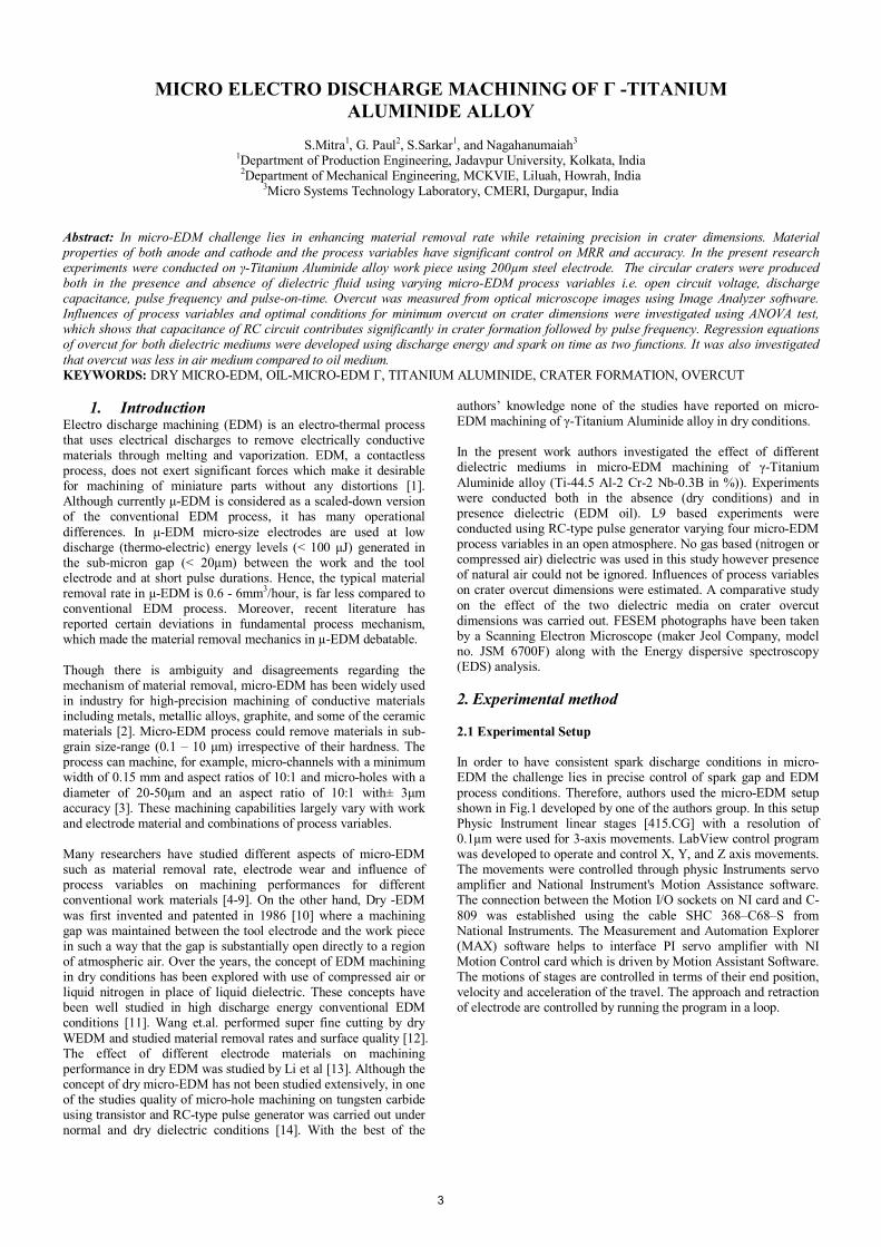
(a) Experimental setup
(b) Typical discharge voltage and current signals Fig.1 Micro-EDM system developed at MST Lab, CMERI
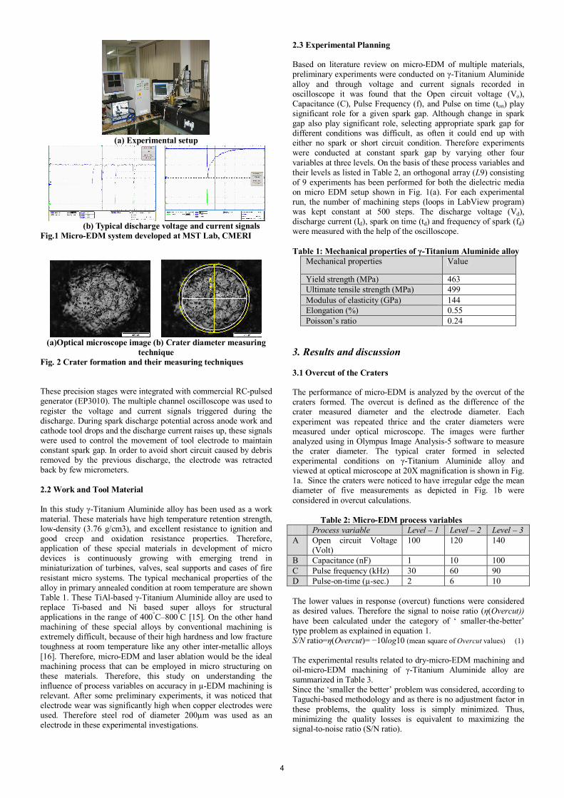
(a)Optical microscope image (b) Crater diameter measuring
technique Fig. 2 Crater formation and their measuring techniques
These precision stages were integrated with commercial RC-pulsed generator (EP3010). The multiple channel oscilloscope was used to register the voltage and current signals triggered during the discharge. During spark discharge potential across anode work and cathode tool drops and the discharge current raises up, these signals were used to control the movement of tool electrode to maintain constant spark gap. In order to avoid short circuit caused by debris removed by the previous discharge, the electrode was retracted back by few micrometers. 2.2 Work and Tool Material In this study γ-Titanium Aluminide alloy has been used as a work material. These materials have high temperature retention strength, low-density (3.76 g/cm3), and excellent resistance to ignition and good creep and oxidation resistance properties. Therefore, application of these special materials in development of micro devices is continuously growing with emerging trend in miniaturization of turbines, valves, seal supports and cases of fire resistant micro systems. The typical mechanical properties of the alloy in primary annealed condition at room temperature are shown Table 1. These TiAl-based γ-Titanium Aluminide alloy are used to replace Ti-based and Ni based super alloys for structural applications in the range of 400°C–800°C [15]. On the other hand machining of these special alloys by conventional machining is extremely difficult, because of their high hardness and low fracture toughness at room temperature like any other inter-metallic alloys [16]. Therefore, micro-EDM and laser ablation would be the ideal machining process that can be employed in micro structuring on these materials. Therefore, this study on understanding the influence of process variables on accuracy in µ-EDM machining is relevant. After some preliminary experiments, it was noticed that electrode wear was significantly high when copper electrodes were used. Therefore steel rod of diameter 200µm was used as an electrode in these experimental investigations.
2.3 Experimental Planning Based on literature review on micro-EDM of multiple materials, preliminary experiments were conducted on γ-Titanium Aluminide alloy and through voltage and current signals recorded in oscilloscope it was found that the Open circuit voltage (Vo), Capacitance (C), Pulse Frequency (f), and Pulse on time (ton) play significant role for a given spark gap. Although change in spark gap also play significant role, selecting appropriate spark gap for different conditions was difficult, as often it could end up with either no spark or short circuit condition. Therefore experiments were conducted at constant spark gap by varying other four variables at three levels. On the basis of these process variables and their levels as listed in Table 2, an orthogonal array (L9) consisting of 9 experiments has been performed for both the dielectric media on micro EDM setup shown in Fig. 1(a). For each experimental run, the number of machining steps (loops in LabView program) was kept constant at 500 steps. The discharge voltage (Vd), discharge current (Id), spark on time (td) and frequency of spark (fd) were measured with the help of the oscilloscope. Table 1: Mechanical properties of γ-Titanium Aluminide alloy
Mechanical properties Value
Yield strength (MPa) 463 Ultimate tensile strength (MPa) 499 Modulus of elasticity (GPa) 144 Elongation (%) 0.55 Poisson’s ratio 0.24
3. Results and discussion 3.1 Overcut of the Craters The performance of micro-EDM is analyzed by the overcut of the craters formed. The overcut is defined as the difference of the crater measured diameter and the electrode diameter. Each experiment was repeated thrice and the crater diameters were measured under optical microscope. The images were further analyzed using in Olympus Image Analysis-5 software to measure the crater diameter. The typical crater formed in selected experimental conditions on γ-Titanium Aluminide alloy and viewed at optical microscope at 20X magnification is shown in Fig. 1a. Since the craters were noticed to have irregular edge the mean diameter of five measurements as depicted in Fig. 1b were considered in overcut calculations. Table 2: Micro-EDM process variables Process variable Level – 1 Level – 2 Level – 3 A Open circuit Voltage
(Volt) 100 120 140
B Capacitance (nF) 1 10 100 C Pulse frequency (kHz) 30 60 90 D Pulse-on-time (µ-sec.) 2 6 10 The lower values in response (overcut) functions were considered as desired values. Therefore the signal to noise ratio (η(Overcut)) have been calculated under the category of ‘ smaller-the-better’ type problem as explained in equation 1. S/N ratio=η(Overcut)= −10log10 (mean square of Overcut values) (1) The experimental results related to dry-micro-EDM machining and oil-micro-EDM machining of γ-Titanium Aluminide alloy are summarized in Table 3. Since the ‘smaller the better’ problem was considered, according to Taguchi-based methodology and as there is no adjustment factor in these problems, the quality loss is simply minimized. Thus, minimizing the quality losses is equivalent to maximizing the signal-to-noise ratio (S/N ratio).
4
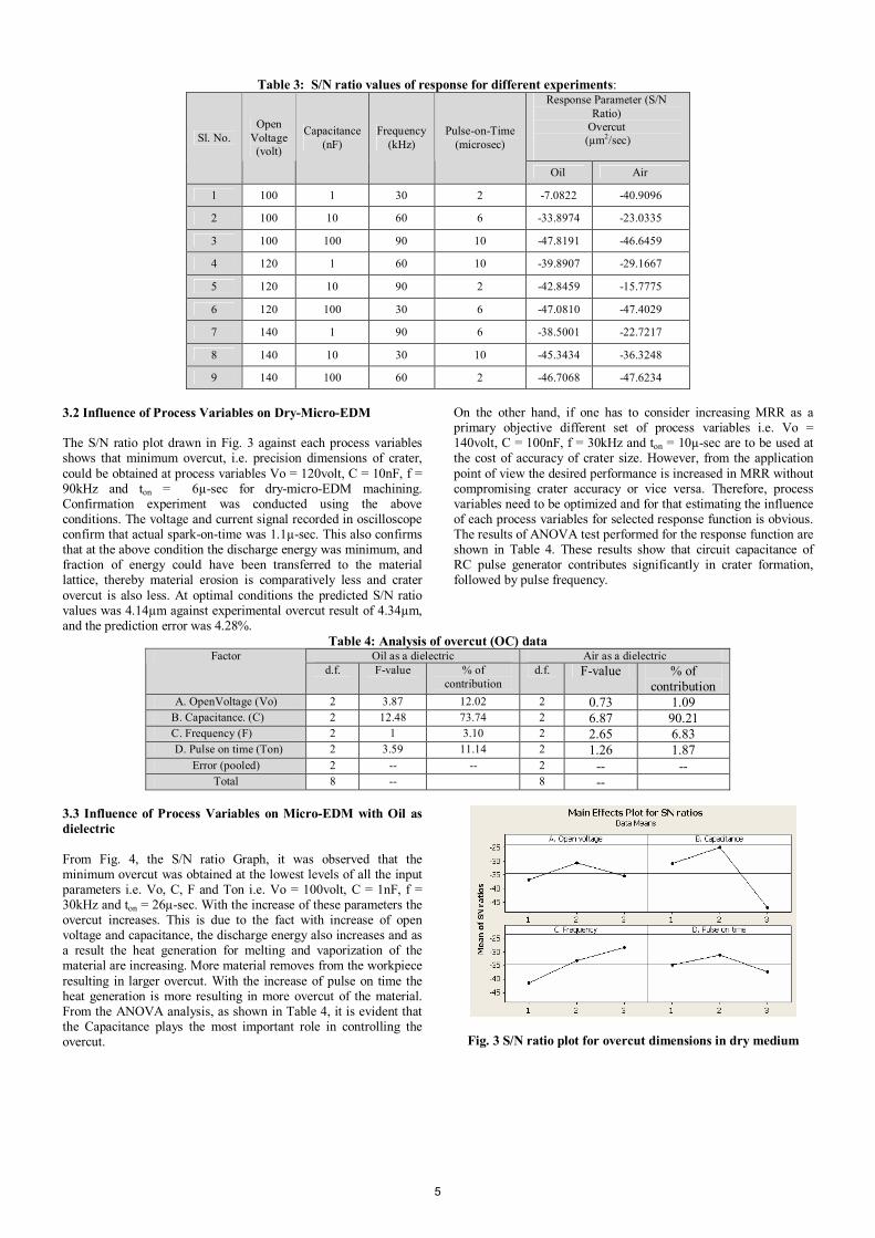
Table 3: S/N ratio values of response for different experiments:
Response Parameter (S/N Ratio)
Overcut (µm2/sec)
Sl. No.
Open Voltage (volt)
Capacitance (nF)
Frequency (kHz)
Pulse-on-Time (microsec)
Oil Air
1 100 1 30 2 -7.0822 -40.9096
2 100 10 60 6 -33.8974 -23.0335
3 100 100 90 10 -47.8191 -46.6459
4 120 1 60 10 -39.8907 -29.1667
5 120 10 90 2 -42.8459 -15.7775
6 120 100 30 6 -47.0810 -47.4029
7 140 1 90 6 -38.5001 -22.7217
8 140 10 30 10 -45.3434 -36.3248
9 140 100 60 2 -46.7068 -47.6234
3.2 Influence of Process Variables on Dry-Micro-EDM The S/N ratio plot drawn in Fig. 3 against each process variables shows that minimum overcut, i.e. precision dimensions of crater, could be obtained at process variables Vo = 120volt, C = 10nF, f = 90kHz and ton = 6µ-sec for dry-micro-EDM machining. Confirmation experiment was conducted using the above conditions. The voltage and current signal recorded in oscilloscope confirm that actual spark-on-time was 1.1µ-sec. This also confirms that at the above condition the discharge energy was minimum, and fraction of energy could have been transferred to the material lattice, thereby material erosion is comparatively less and crater overcut is also less. At optimal conditions the predicted S/N ratio values was 4.14µm against experimental overcut result of 4.34µm, and the prediction error was 4.28%.
On the other hand, if one has to consider increasing MRR as a primary objective different set of process variables i.e. Vo = 140volt, C = 100nF, f = 30kHz and ton = 10µ-sec are to be used at the cost of accuracy of crater size. However, from the application point of view the desired performance is increased in MRR without compromising crater accuracy or vice versa. Therefore, process variables need to be optimized and for that estimating the influence of each process variables for selected response function is obvious. The results of ANOVA test performed for the response function are shown in Table 4. These results show that circuit capacitance of RC pulse generator contributes significantly in crater formation, followed by pulse frequency.
Table 4: Analysis of overcut (OC) data Oil as a dielectric Air as a dielectric Factor
d.f. F-value % of contribution
d.f. F-value % of contribution
A. OpenVoltage (Vo) 2 3.87 12.02 2 0.73 1.09 B. Capacitance. (C) 2 12.48 73.74 2 6.87 90.21 C. Frequency (F) 2 1 3.10 2 2.65 6.83
D. Pulse on time (Ton) 2 3.59 11.14 2 1.26 1.87 Error (pooled) 2 -- -- 2 -- --
Total 8 -- 8 --
3.3 Influence of Process Variables on Micro-EDM with Oil as dielectric From Fig. 4, the S/N ratio Graph, it was observed that the minimum overcut was obtained at the lowest levels of all the input parameters i.e. Vo, C, F and Ton i.e. Vo = 100volt, C = 1nF, f = 30kHz and ton = 26µ-sec. With the increase of these parameters the overcut increases. This is due to the fact with increase of open voltage and capacitance, the discharge energy also increases and as a result the heat generation for melting and vaporization of the material are increasing. More material removes from the workpiece resulting in larger overcut. With the increase of pulse on time the heat generation is more resulting in more overcut of the material. From the ANOVA analysis, as shown in Table 4, it is evident that the Capacitance plays the most important role in controlling the overcut.
Fig. 3 S/N ratio plot for overcut dimensions in dry medium
5
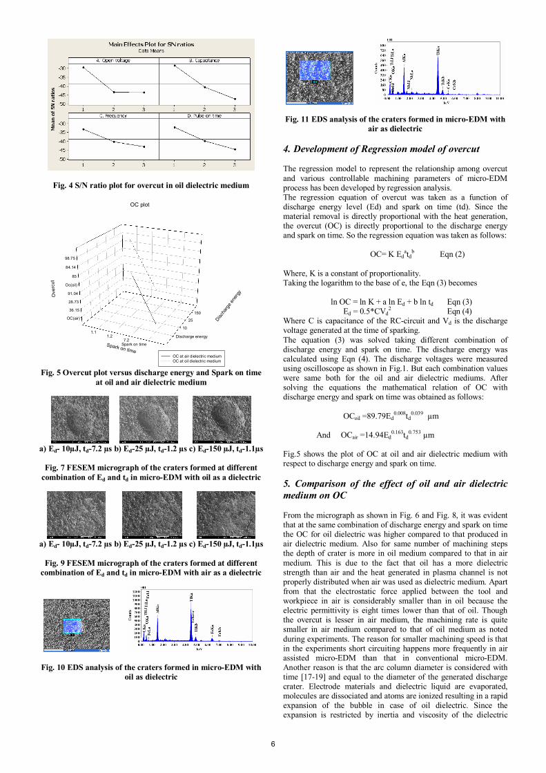
Fig. 4 S/N ratio plot for overcut in oil dielectric medium
OC(air)
36.15
28.73
91.04
Oc(oil)
85
84.14
98.75
Discharge energy
10
25
150
Spark on time7.2
1.21.1
Ove
rcut
Discha
rge e
nerg
y
Spark on time
OC plot
OC at air dielectric mediumOC at oil dielectric medium
Fig. 5 Overcut plot versus discharge energy and Spark on time at oil and air dielectric medium
a) Ed- 10µJ, td-7.2 µs b) Ed-25 µJ, td-1.2 µs c) Ed-150 µJ, td-1.1µs
Fig. 7 FESEM micrograph of the craters formed at different
combination of Ed and td in micro-EDM with oil as a dielectric
a) Ed- 10µJ, td-7.2 µs b) Ed-25 µJ, td-1.2 µs c) Ed-150 µJ, td-1.1µs
Fig. 9 FESEM micrograph of the craters formed at different
combination of Ed and td in micro-EDM with air as a dielectric
Fig. 10 EDS analysis of the craters formed in micro-EDM with oil as dielectric
Fig. 11 EDS analysis of the craters formed in micro-EDM with air as dielectric
4. Development of Regression model of overcut The regression model to represent the relationship among overcut and various controllable machining parameters of micro-EDM process has been developed by regression analysis. The regression equation of overcut was taken as a function of discharge energy level (Ed) and spark on time (td). Since the material removal is directly proportional with the heat generation, the overcut (OC) is directly proportional to the discharge energy and spark on time. So the regression equation was taken as follows: OC= K Ed
atdb Eqn (2) Where, K is a constant of proportionality. Taking the logarithm to the base of e, the Eqn (3) becomes ln OC = ln K + a ln Ed + b ln td Eqn (3) Ed = 0.5*CVd
2 Eqn (4) Where C is capacitance of the RC-circuit and Vd is the discharge voltage generated at the time of sparking. The equation (3) was solved taking different combination of discharge energy and spark on time. The discharge energy was calculated using Eqn (4). The discharge voltages were measured using oscilloscope as shown in Fig.1. But each combination values were same both for the oil and air dielectric mediums. After solving the equations the mathematical relation of OC with discharge energy and spark on time was obtained as follows: OCoil =89.79Ed
0.008td0.039 µm
And OCair =14.94Ed
0.163td0.753 µm
Fig.5 shows the plot of OC at oil and air dielectric medium with respect to discharge energy and spark on time.
5. Comparison of the effect of oil and air dielectric medium on OC From the micrograph as shown in Fig. 6 and Fig. 8, it was evident that at the same combination of discharge energy and spark on time the OC for oil dielectric was higher compared to that produced in air dielectric medium. Also for same number of machining steps the depth of crater is more in oil medium compared to that in air medium. This is due to the fact that oil has a more dielectric strength than air and the heat generated in plasma channel is not properly distributed when air was used as dielectric medium. Apart from that the electrostatic force applied between the tool and workpiece in air is considerably smaller than in oil because the electric permittivity is eight times lower than that of oil. Though the overcut is lesser in air medium, the machining rate is quite smaller in air medium compared to that of oil medium as noted during experiments. The reason for smaller machining speed is that in the experiments short circuiting happens more frequently in air assisted micro-EDM than that in conventional micro-EDM. Another reason is that the arc column diameter is considered with time [17-19] and equal to the diameter of the generated discharge crater. Electrode materials and dielectric liquid are evaporated, molecules are dissociated and atoms are ionized resulting in a rapid expansion of the bubble in case of oil dielectric. Since the expansion is restricted by inertia and viscosity of the dielectric
6
liquid, the pressure inside the bubble becomes extremely high and liquid expands with the velocity of several tens m/s ([20, 21]. So the bubble formation plays important role in material removal rate [10]. As there is no bubble formation in air dielectric as compared to oil dielectric, the material removal rate is smaller in the case of air dielectric and also the overcut of the craters are smaller in case of air dielectric. It is also established by the FESEM micrograph of the craters formed at three different energy levels in micro-EDM as shown in the Fig. 7 and Fig. 9 that the material removal in case of air dielectric is quite less compared to that in the case of oil dielectric. The EDS analysis of the craters as shown in Fig. 10 and Fig. 11 indicates the composition of the materials at the craters. 6. Conclusions This paper explains the experimental results on dry-micro-EDM machining and oil-micro-EDM machining of γ-Titanium Aluminide alloy. The following conclusions are noted.
1. Micro-EDM in dry conditions can be effectively used for micro machining of γ-Titanium Aluminide alloy. The high heat and fire resistance property of this alloy prevents arcing issues during shot circuiting with low energy discharge. No deformation appeared in the work material.
2. For precision machining i.e. smaller overcut dimensions of crater, lower energy is desirable, whereas MRR is low in these conditions.
3. For the purpose of optimization of process variables, ANOVA test was performed that highlights that circuit capacitance of RC pulse generator contributes significantly in the accuracy of machining i.e. overcut of craters.
4. It was observed that for given micro-EDM process parameters the crater depth formation by a single discharge in the absence of dielectric liquid (dry-micro-EDM) is relatively small, compared to machining in presence of dielectric oil. This observation remained unchanged even after multiple discharges. This may be attributed to low dielectric strength and low electric permittivity of air surrounding the discharge point. Due to low dielectric strength, the denser and cold plasma [22] produced by low energy discharge might not be point focused in the absence of liquid dielectric. At the same time electrostatic force induced between the tool and work piece is considerably small in dry machining. Authors are investigating further to confirm the above analogy.
5. A regression model was developed to correlate the effect of discharge energy and spark on time on overcut. From the micrograph it has been observed that at the same set of discharge energy and spark on time the overcut was more in oil medium and also from experiments and FESEM micrographs it was evident that machining speed was also higher in oil medium compared to that in air medium. So for precision machining air medium is preferable at the cost of machining time.
7. Acknowledgement Authors acknowledge the financial support provided by Council of Scientific and Industrial Research (CSIR), New Delhi, India. The technical support and suggestions extended by other researchers at Micro Systems Technology Laboratory in Central Mechanical and Engineering Research Institute, CMERI Durgapur, India are also acknowledged. 8. References [1] Masuzawa, T., 2000, State of the art of micromachining. Annals of the CIRP 49(2), pp. 473–488. [2] Puertas, I., Luis, C.J. and Alvarez, L., 2004, Analysis of the influence of EDM parameters on surface quality, MRR and EW of
WC–Co. Journal of Material. Processing Technology, 153-154, pp.1026–1032. [3] Uruarte, L. Herrero,A. Ivanov,A. Oosterling,H. Staemmler,L. Tang,P.T. and Allen,D. , 2006, Comparison between micro fabrication technologies for metal tooling. Special Issue paper. Pro. IMechE. 220, pp.1665-1676 [4] Yu Z.Y., Zhang Y., Li J., Luan J., Zhao F. and Guo D., 2009, High aspect ratio micro-hole drilling aided with ultrasonic vibration and planetary movement of electrode by micro-EDM, CIRP Annals - Manufacturing Technology 58(2), pp.213–216. [5] Jahan M.P., Wong Y.S. and Rahman M., 2009a, A study on the fine-finish die-sinking micro-EDM of tungsten carbide using different electrode materials, Journal of Materials Processing Technology, 209, pp. 3956–3967. [6] Liu Kun , Lauwers Bert, Reynaerts Dominiek 2009, Process capabilities of Micro-EDM and its applications, Int. Journal of Adv Manufacturing Technology DOI 10.1007/s00170-009-2056-1. [7] Uhlmann Eckart and Roehner Markus, 2008, Investigations on reduction of tool electrode wear in micro-EDM using novel electrode materials, CIRP Journal of Manufacturing Science and Technology, 1, pp. 92–96. [8] Kurnia W, Tan P C, Yeo S H and Wong M, 2008, Analytical approximation of the erosion rate and electrode wear in micro electrical discharge machining, J. Micromech. Microeng. 18, pp. 085011-085018. [9] Sundaram Murali M., Pavalarajan Ganesh B., and Rajurkar Kamlakar P., 2008, A Study on Process Parameters of Ultrasonic Assisted Micro EDM Based on Taguchi Method, Journal of Materials Engineering and Performance, 17, pp. 210–215. [10] Inoue Kiyoshi, 1986 Dry-cut EDM with debris sweeping means, United States Patent, patent number 4590352, [11] Kunieda M., Lauwers B., Rajurkar K.P. and Schumacher B.M., 2005, Advancing EDM through fundamental insight into the process. Annals of the CIRP, 54 (2), pp. 599-622. [12] Tong Wang, Xinfu Zhang and Xuefang Zhao, 2006, Study of finishing cut with dry WEDM, Journal of Materials science forum, 532-533, pp. 273-276. [13] Li Liqing, Wang Zhenlong, Guo Yongfeng and Bai Jicheng, 2006, Experimental research on machining performance of electrode materials in dry EDM, Journal of materials science forum, 532-533, pp. 173-176. [14] Jahan M.P., Wong Y.S. and Rahman M., 2009b, A study on the quality micro-hole machining of tungsten carbide by micro-EDM process using transistor and RC-type pulse generator, Journal of Materials Processing Technology, 209, pp. 1706–1716 [15] Voice W., 1999, Future use of gamma titanium aluminides by Rolls-Royce, Aircraft Eng. Aero Tech. 71 (4), pp. 337–340. [16] Pan B., Kim D.J., Kim B.M. and Dean T.A., 2001, Incremental deformation and the forgeability of γ-titanium aluminide, Int. J. Mach. Tools Manuf., 41, pp. 749–759. [17] Zingerman, A.S., 1956, Propagation of a discharge column, Soviet Physics-Technical Physics 1(1), 5, pp. 992-996. [18] Soneys, R., Van Dijck, F., 1971, Investigations of EDM operations by means of thermo mathematical models, Annals of the CIRP, 20, pp. 35-36. [19] Soneys, R., Van Dijck, F., 1972, Plasma channel diameter growth affects stock removal, Annals of the CIRP, 21, pp. 39-40. [20] Eckman P.K., Williams E. M., 1960, Plasma dynamics in arc formed by low-voltage sparkover of a liquid dielectric, Applied Science Research, Section B, 8, pp. 299-320. [21] Ikeda, M., 1972, The movement of a bubble in the gap depending on the single electrical discharge (1st Report), J. JSME, 6, 11, pp. 12-25 (in Japanese). [22] Nagahanumaiah, Ramkumar J. Glumac Nick, Kapoor S.G. and DeVor R.E., 2008, Characterization of plasma in micro-EDM using optical emission spectroscopy. Third Int. Conference on Micro Manufacturing September 9-11, Carnegie Mellon University, USA.
7