HPGP Gearhead Series Gearhead Series High ... - … 14, 20, 32, 50, 65Gearhead - Standard backlash...
20
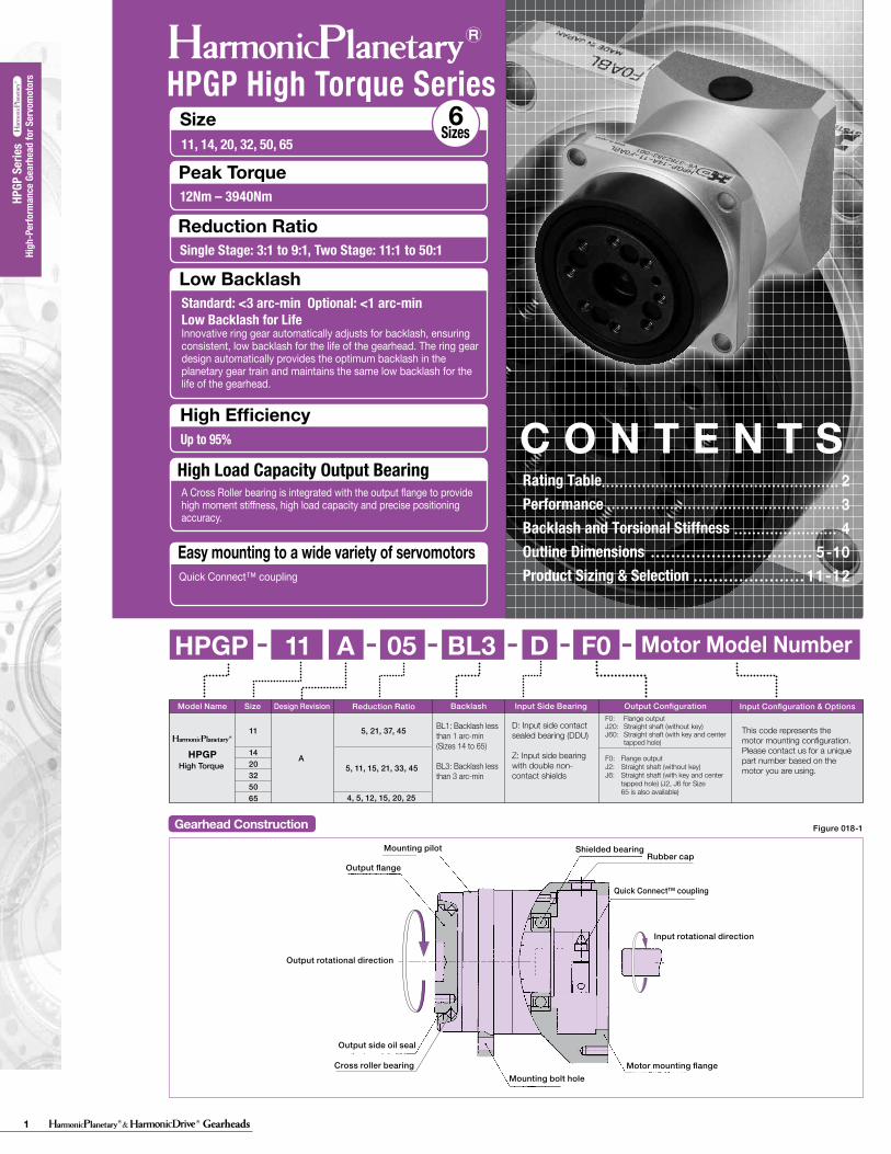
1 Gearheads High-Performance Gearhead for Servomotors HPGP Series HPGP High Torque Series Gearhead Construction Mounting pilot Output flange Output rotational direction Output side oil seal Cross roller bearing Mounting bolt hole Motor mounting flange Input rotational direction Shielded bearing Rubber cap Figure 018-1 Quick Connect™ coupling 2 3 4 5-10 11-12 Rating Table Performance Backlash and Torsional Stiffness Outline Dimensions Product Sizing & Selection CONTENTS Size 11, 14, 20, 32, 50, 65 Sizes 6 Peak Torque Reduction Ratio Easy mounting to a wide variety of servomotors Single Stage: 3:1 to 9:1, Two Stage: 11:1 to 50:1 12Nm – 3940Nm Low Backlash High Efficiency Up to 95% Standard: <3 arc-min Optional: <1 arc-min Low Backlash for Life Innovative ring gear automatically adjusts for backlash, ensuring consistent, low backlash for the life of the gearhead. The ring gear design automatically provides the optimum backlash in the planetary gear train and maintains the same low backlash for the life of the gearhead. Quick Connect™ coupling High Load Capacity Output Bearing A Cross Roller bearing is integrated with the output flange to provide high moment stiffness, high load capacity and precise positioning accuracy. HPGP 11 A 05 BL3 F0 D - - - - - - HPGP A 5, 21, 37, 45 5, 11, 15, 21, 33, 45 4, 5, 12, 15, 20, 25 Reduction Ratio Input Configuration & Options 11 14 20 32 50 65 High Torque This code represents the motor mounting configuration. Please contact us for a unique part number based on the motor you are using. D: Input side contact sealed bearing (DDU) Z: Input side bearing with double non- contact shields BL1: Backlash less than 1 arc-min (Sizes 14 to 65) BL3: Backlash less than 3 arc-min F0: Flange output J2: Straight shaft (without key) J6: Straight shaft (with key and center tapped hole) (J2, J6 for Size 65 is also available) F0: Flange output J20: Straight shaft (without key) J60: Straight shaft (with key and center tapped hole) Model Name Size Design Revision Output Configuration Input Side Bearing Backlash Motor Model Number
Transcript of HPGP Gearhead Series Gearhead Series High ... - … 14, 20, 32, 50, 65Gearhead - Standard backlash...
1 Gearheads
HPGP Gearhead Series
Dimension Table
Backlash and Tosional Stiffness
A
A
BD
BD
0-TR×0.15
TR×0.15
-TR
TR(4)
(5)(1)
(2)
(3)
θD
TTL
A/B
See Fig. 021-1, Table 021-1, Table 021-2
See Fig. 021-1See Fig. 021-1, Table 021-1 to 2
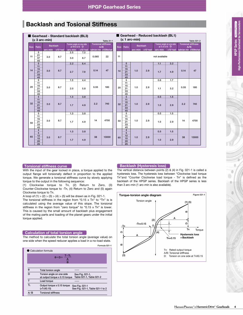
θ=D+
BA
T-TL
(Unit: mm)
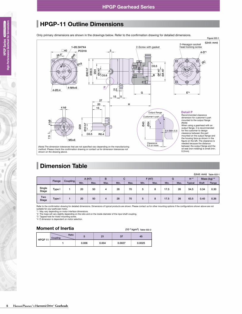
HPGP-11 Outline DimensionsOnly primary dimensions are shown in the drawings below. Refer to the confirmation drawing for detailed dimensions.
Formula 021-1
Table 022-1
28.5°
7.5
0 -0.1
E*4
□40
4 h9
4 h9
Ø10
h7
Ø29
1520
27
Ø5
H7
Ø39
.5Ø
40 h
7
ØA
H7
3
15
H
G5
2.2
B
Ø24
P
1-Ø2.5H7X4PCD18
4-M4×64-Ø3.4
R0.4C0.5
C0.6
C0.5
M3×6
4-D*3
ØF
H7
ØC
Ø46
Ø18
Table 21-1
arc min ×10-4rad arc min ×10-4radD A/B
kgfm/arc min ×100Nm/rad
11
14
20
32
50
65
5213745511152133455111521334551115213345511152133454512152025
3.0
3.0
3.0
3.0
3.0
3.0
8.7
8.7
8.7
8.7
8.7
8.7
2.5
3.0
2.2
2.7
1.5
2.0
1.3
1.7
1.3
1.7
1.3
1.7
7.3
8.7
6.4
7.9
4.4
5.8
3.8
4.9
3.8
4.9
3.8
4.9
0.065
0.14
0.55
2.2
14
38
22
47
180
740
4700
13000
arc min ×10-4rad arc min ×10-4radD A/B
kgfm/arc min ×100Nm/rad
14
20
32
50
65
511152133455111521334551115213345511152133454512152025
1.0
1.0
1.0
1.0
1.0
2.9
2.9
2.9
2.9
2.9
1.1
1.7
0.6
1.1
0.5
1.0
0.5
1.0
0.5
1.0
3.2
4.9
1.7
3.2
1.5
2.9
1.5
2.9
1.5
2.9
0.14
0.55
2.2
14
38
47
180
740
4700
13000
Ø24
Ø40
Detail PCustomer's part
0.4 (Min.0.2)
Clearance0.5 or more
Recommended clearance dimension for customer's part mounted to the output flange(Note)When using a gearhead with an output flange, it is recommended for the customer to design clearance between the part mounted on the output flange and the housing face as shown in the figure on the left. The clearance is needed because the distance between the output flange and the oil seal (non-rotating) is small (min. 0.2mm).
Output flange
2-Hexagon socket head locking screw2-Screw with gasket
018 019
HPGP Gearhead Series
Figure 022-1
HPGP Gearhead Series
■ Gearhead - Standard backlash (BL3) (≤ 3 arc-min)
Torsional stiffnessRatioSizeRatioSize Backlash Torsion angle on one side
at TR X 0.15Torsional stiffness
BacklashTorsion angle on one side at TR X 0.15
■ Gearhead - Reduced backlash (BL1) (≤ 1 arc-min)
With the input of the gear locked in place, a torque applied to the output flange will torsionally deflect in proportion to the applied torque. We generate a torsional stiffness curve by slowly applying torque to the output in the following sequence:(1) Clockwise torque to TR, (2) Return to Zero, (3) Counter-Clockwise torque to -TR, (4) Return to Zero and (5) again Clockwise torque to TR. A loop of (1) > (2) > (3) > (4) > (5) will be drawn as in Fig. 021-1.The torsional stiffness in the region from “0.15 x TR” to “TR” is is calculated using the average value of this slope. The torsional stiffness in the region from “zero torque” to “0.15 x TR” is lower. This is caused by the small amount of backlash plus engagement of the mating parts and loading of the planet gears under the initial torque applied.
Torsional stiffness curveThe vertical distance between points (2) & (4) in Fig. 021-1 is called a hysteresis loss. The hysteresis loss between “Clockwise load torque TR”and “Counter Clockwise load torque - TR” is defined as the backlash of the HPGP series. Backlash of the HPGP series is less than 3 arc-min (1 arc-min is also available).
Backlash (Hysteresis loss)
The method to calculate the total torsion angle (average value) on one side when the speed reducer applies a load in a no-load state.
Calculation of total torsion angle
Torque-torsion angle diagram
Torsion angle
TR: Rated output torqueA/B: Torsional stiffnessD: Torsion on one side at TRX0.15
Hysteresis loss = Backlash
Torque
● Calculation formula
Total torsion angle
Load torque
Torsional stiffness
Torsion angle on one sideat output torque x 0.15 torque
Output torque x 0.15 torque(=TRX0.15)
(Note) The dimension tolerances that are not specified vary depending on the manufacturing method. Please check the confirmation drawing or contact us for dimension tolerances not shown on the drawing above.
High
-Per
form
ance
Gea
rhea
d fo
r Ser
vom
otor
s
High
-Per
form
ance
Gea
rhea
d fo
r Ser
vom
otor
s HP
GP S
eries
HPGP
Ser
ies
11 not available
Mass (kg) *2
Shaft
B
1 20 50 4 28 70 5 8 17.5 26 0.34 0.30
A (H7) C GF (H7)FlangeMin. Max. Max. Min. Max. Min. Max. Min. Max.
54.5
H *1
TypicalFlange
Type I
1 20 50 4 28 70 5 8 17.5 26 0.40 0.3663.5Type I
SingleStage
TwoStage
Coupling
Refer to the confirmation drawing for detailed dimensions. Dimensions of typical products are shown. Please contact us for other mounting options if the configurations shown above are not suitable for your particular motor. *1 May vary depending on motor interface dimensions. *2 The mass will vary slightly depending on the ratio and on the inside diameter of the input shaft coupling.*3 Tapped hole for motor mounting screw.*4 E dimension is dependent on motor selection.
Moment of Inertia Table 022-2
5
0.006
21
0.004
37
0.0027
45
0.00251
CouplingRatio
HPGP 11
(Unit: mm)Table 021-2
Figure 021-1
(10-4 kgm2)Hi
gh-p
erfo
rman
ce G
ear H
eads
for S
ervo
Mot
ors s
eries
HPGP
serie
sHi
gh-p
erfo
rman
ce G
ear H
eads
for S
ervo
Mot
ors s
eries
HPG
serie
sHi
gh-p
erfo
rman
ce G
ear H
eads
for S
ervo
Mot
ors s
eries
CSG-
GH se
ries
High
-per
form
ance
Gea
r Hea
ds fo
r Ser
vo M
otor
s ser
iesCS
F-GH
serie
sHi
gh-p
erfo
rman
ce G
ear H
eads
for S
ervo
Mot
ors s
eries
HPG
serie
s (Or
thog
onal
Sha
ft Ty
pe)
HPGP High Torque Series
Gearhead ConstructionMounting pilot
Output flange
Output rotational direction
Output side oil seal
Cross roller bearingMounting bolt hole
Motor mounting flange
Input rotational direction
Shielded bearingRubber cap
Figure 018-1
Quick Connect™ coupling
234
5-1011-12
Rating TablePerformanceBacklash and Torsional Stiffness Outline DimensionsProduct Sizing & Selection
C O N T E N T S
Size11, 14, 20, 32, 50, 65
Sizes6
Peak Torque
Reduction Ratio
Easy mounting to a wide variety of servomotors
Single Stage: 3:1 to 9:1, Two Stage: 11:1 to 50:1
12Nm – 3940Nm
Low Backlash
High EfficiencyUp to 95%
Standard: <3 arc-min Optional: <1 arc-min Low Backlash for LifeInnovative ring gear automatically adjusts for backlash, ensuring consistent, low backlash for the life of the gearhead. The ring gear design automatically provides the optimum backlash in the planetary gear train and maintains the same low backlash for the life of the gearhead.
Quick Connect™ coupling
High
-per
form
ance
Gea
r Hea
ds fo
r Ser
vo M
otor
s ser
iesH
PGP
serie
sHi
gh-p
erfo
rman
ce G
ear H
eads
for S
ervo
Mot
ors s
eries
HPG
serie
sHi
gh-p
erfo
rman
ce G
ear H
eads
for S
ervo
Mot
ors s
eries
CSG-
GH se
ries
High
-per
form
ance
Gea
r Hea
ds fo
r Ser
vo M
otor
s ser
iesCS
F-GH
serie
sHi
gh-p
erfo
rman
ce G
ear H
eads
for S
ervo
Mot
ors s
eries
HPG
serie
s (Or
thog
onal
Sha
ft Ty
pe)
013014
016・017018019
Structural DrawingModel Number SelectionRating Table・Performance TableTorque - Torsion CharacteristicDimensional Outline Drawing
035036・037038・039040・041
042043044045
Structural DrawingTerms on the Rating Table・On Life・On IntensityOn Rigidity・On Vibration・Efficiency CharacteristicsModel Number SelectionRating Table・Racheting Torque・Buckling TorquePerformance TableRigidity (Spring constant) ・ Hysteresis Loss ・ Max. Backlash QuantityDimensional Outline Drawing
CSF-GH Series Standard Type050051052053
Rating Table・Racheting Torque・Buckling TorquePerformance TableRigidity (Spring constant) ・ Hysteresis Loss ・ Max. Backlash QuantityDimensional Outline Drawing
HPGP Series
026・027028029
Rating Table・Performance TableTorque - Torsion CharacteristicDimensional Outline Drawing
HPG Series
CSG-GH Series High-torque Type
CONTENTSGearhead Series
High Load Capacity Output BearingA Cross Roller bearing is integrated with the output flange to provide high moment stiffness, high load capacity and precise positioning accuracy.
HPGP 11 A 05 BL3 F0D -- ----
HPGP A
5, 21, 37, 45
5, 11, 15, 21, 33, 45
4, 5, 12, 15, 20, 25
Reduction Ratio Input Configuration & Options
11
1420325065
High Torque
This code represents the motor mounting configuration. Please contact us for a unique part number based on the motor you are using.
D: Input side contact sealed bearing (DDU)
Z: Input side bearing with double non- contact shields
BL1: Backlash less than 1 arc-min (Sizes 14 to 65)
BL3: Backlash less than 3 arc-min
F0: Flange outputJ2: Straight shaft (without key)J6: Straight shaft (with key and center
tapped hole) (J2, J6 for Size 65 is also available)
F0: Flange outputJ20: Straight shaft (without key)J60: Straight shaft (with key and center
tapped hole)
Model Name Size Design Revision Output ConfigurationInput Side BearingBacklash
Motor Model Number
2Gearheads
HPGP Gearhead Series
Dimension Table
Backlash and Tosional Stiffness
A
A
BD
BD
0-TR×0.15
TR×0.15
-TR
TR(4)
(5)(1)
(2)
(3)
θD
TTL
A/B
See Fig. 021-1, Table 021-1, Table 021-2
See Fig. 021-1See Fig. 021-1, Table 021-1 to 2
θ=D+
BA
T-TL
(Unit: mm)
HPGP-11 Outline DimensionsOnly primary dimensions are shown in the drawings below. Refer to the confirmation drawing for detailed dimensions.
Formula 021-1
Table 022-1
28.5°
7.5
0 -0.1
E*4
□40
4 h9
4 h9
Ø10
h7
Ø29
1520
27
Ø5
H7
Ø39
.5Ø
40 h
7
ØA
H7
3
15
H
G5
2.2
BØ
24
P
1-Ø2.5H7X4PCD18
4-M4×64-Ø3.4
R0.4C0.5
C0.6
C0.5
M3×6
4-D*3
ØF
H7
ØC
Ø46
Ø18
Table 21-1
arc min ×10-4rad arc min ×10-4radD A/B
kgfm/arc min ×100Nm/rad
11
14
20
32
50
65
5213745511152133455111521334551115213345511152133454512152025
3.0
3.0
3.0
3.0
3.0
3.0
8.7
8.7
8.7
8.7
8.7
8.7
2.5
3.0
2.2
2.7
1.5
2.0
1.3
1.7
1.3
1.7
1.3
1.7
7.3
8.7
6.4
7.9
4.4
5.8
3.8
4.9
3.8
4.9
3.8
4.9
0.065
0.14
0.55
2.2
14
38
22
47
180
740
4700
13000
arc min ×10-4rad arc min ×10-4radD A/B
kgfm/arc min ×100Nm/rad
14
20
32
50
65
511152133455111521334551115213345511152133454512152025
1.0
1.0
1.0
1.0
1.0
2.9
2.9
2.9
2.9
2.9
1.1
1.7
0.6
1.1
0.5
1.0
0.5
1.0
0.5
1.0
3.2
4.9
1.7
3.2
1.5
2.9
1.5
2.9
1.5
2.9
0.14
0.55
2.2
14
38
47
180
740
4700
13000
Ø24
Ø40
Detail PCustomer's part
0.4 (Min.0.2)
Clearance0.5 or more
Recommended clearance dimension for customer's part mounted to the output flange(Note)When using a gearhead with an output flange, it is recommended for the customer to design clearance between the part mounted on the output flange and the housing face as shown in the figure on the left. The clearance is needed because the distance between the output flange and the oil seal (non-rotating) is small (min. 0.2mm).
Output flange
2-Hexagon socket head locking screw2-Screw with gasket
018 019
HPGP Gearhead Series
Figure 022-1
HPGP Gearhead Series
■ Gearhead - Standard backlash (BL3) (≤ 3 arc-min)
Torsional stiffnessRatioSizeRatioSize Backlash Torsion angle on one side
at TR X 0.15Torsional stiffness
BacklashTorsion angle on one side at TR X 0.15
■ Gearhead - Reduced backlash (BL1) (≤ 1 arc-min)
With the input of the gear locked in place, a torque applied to the output flange will torsionally deflect in proportion to the applied torque. We generate a torsional stiffness curve by slowly applying torque to the output in the following sequence:(1) Clockwise torque to TR, (2) Return to Zero, (3) Counter-Clockwise torque to -TR, (4) Return to Zero and (5) again Clockwise torque to TR. A loop of (1) > (2) > (3) > (4) > (5) will be drawn as in Fig. 021-1.The torsional stiffness in the region from “0.15 x TR” to “TR” is is calculated using the average value of this slope. The torsional stiffness in the region from “zero torque” to “0.15 x TR” is lower. This is caused by the small amount of backlash plus engagement of the mating parts and loading of the planet gears under the initial torque applied.
Torsional stiffness curveThe vertical distance between points (2) & (4) in Fig. 021-1 is called a hysteresis loss. The hysteresis loss between “Clockwise load torque TR”and “Counter Clockwise load torque - TR” is defined as the backlash of the HPGP series. Backlash of the HPGP series is less than 3 arc-min (1 arc-min is also available).
Backlash (Hysteresis loss)
The method to calculate the total torsion angle (average value) on one side when the speed reducer applies a load in a no-load state.
Calculation of total torsion angle
Torque-torsion angle diagram
Torsion angle
TR: Rated output torqueA/B: Torsional stiffnessD: Torsion on one side at TRX0.15
Hysteresis loss = Backlash
Torque
● Calculation formula
Total torsion angle
Load torque
Torsional stiffness
Torsion angle on one sideat output torque x 0.15 torque
Output torque x 0.15 torque(=TRX0.15)
(Note) The dimension tolerances that are not specified vary depending on the manufacturing method. Please check the confirmation drawing or contact us for dimension tolerances not shown on the drawing above.
High
-Per
form
ance
Gea
rhea
d fo
r Ser
vom
otor
s
High
-Per
form
ance
Gea
rhea
d fo
r Ser
vom
otor
s HP
GP S
eries
HPGP
Ser
ies
11 not available
Mass (kg) *2
Shaft
B
1 20 50 4 28 70 5 8 17.5 26 0.34 0.30
A (H7) C GF (H7)FlangeMin. Max. Max. Min. Max. Min. Max. Min. Max.
54.5
H *1
TypicalFlange
Type I
1 20 50 4 28 70 5 8 17.5 26 0.40 0.3663.5Type I
SingleStage
TwoStage
Coupling
Refer to the confirmation drawing for detailed dimensions. Dimensions of typical products are shown. Please contact us for other mounting options if the configurations shown above are not suitable for your particular motor. *1 May vary depending on motor interface dimensions. *2 The mass will vary slightly depending on the ratio and on the inside diameter of the input shaft coupling.*3 Tapped hole for motor mounting screw.*4 E dimension is dependent on motor selection.
Moment of Inertia Table 022-2
5
0.006
21
0.004
37
0.0027
45
0.00251
CouplingRatio
HPGP 11
(Unit: mm)Table 021-2
Figure 021-1
(10-4 kgm2)
Rating Table
θer :θ1 :θ2 : R :
θer = θ2- Rθ1θer
ϕ1
ϕ2
ϕ7
XX2
X2
X2
11
14
20
32
50
65
5213745511152133455111521334551115213345511152133454512152025
4.02.91.61.48.68.07.45.23.32.41915129.36.44.73327252215118045403624202882401251109584
0.410.290.170.150.880.820.750.530.340.251.91.61.20.950.650.483.42.72.52.31.51.28.24.64.13.72.42.029241311108.6
0.20
0.60
0.640.430.90
1.1
0.931.71.82.0
2.1
1.72.93.74.74.85.14.05.06.07.67.88.9
12
15171921
0.0200.0610.0620.0660.0440.0920.11
0.12
0.0950.170.180.20
0.22
0.170.300.380.480.490.520.410.510.610.780.800.91
1.2
1.51.71.92.1
5.01.30.900.809.84.9
2.9
2.0
2815118.85.94.97338292414131306047402420420360190160130110
0.510.130.0920.082
1.00.50
0.30
0.20
2.91.51.10.900.600.507.43.93.02.41.41.3136.14.84.12.52.0433719161311
5
4
4
4
3
3
14.5
11.6
11.6
11.6
8.7
8.7
±30
±20
±15
±15
±15
±15
Performance TableTable 020-1Table 019-1
Figure 020-1
Table 020-3
Accuracy Input angleActual output angleGear reduction ratio
Repeatability = ± Input speedLoad
HPGP speed reducer surface temperature
3000 rpmNo load
25°C
arc min ×10-4rad arc sec Ncm kgfcm Nm kgfm Ncm kgfcm
016 017
HPGP Gearhead Series HPGP Gearhead Series
High
-per
form
ance
Gea
r Hea
ds fo
r Ser
vo M
otor
s se
ries
HPG
P se
ries
High
-per
form
ance
Gea
r Hea
ds fo
r Ser
vo M
otor
s se
ries
HPG
ser
ies
High
-per
form
ance
Gea
r Hea
ds fo
r Ser
vo M
otor
s se
ries
CSG
-GH
ser
ies
High
-per
form
ance
Gea
r Hea
ds fo
r Ser
vo M
otor
s se
ries
CSF
-GH
ser
ies
High
-per
form
ance
Gea
r Hea
ds fo
r Ser
vo M
otor
s se
ries
HPG
serie
s (Or
thog
onal
Shaf
t Typ
e)
High
-per
form
ance
Gea
r Hea
ds fo
r Ser
vo M
otor
s se
ries
HPG
P se
ries
High
-per
form
ance
Gea
r Hea
ds fo
r Ser
vo M
otor
s se
ries
HPG
ser
ies
High
-per
form
ance
Gea
r Hea
ds fo
r Ser
vo M
otor
s se
ries
CSG
-GH
ser
ies
High
-per
form
ance
Gea
r Hea
ds fo
r Ser
vo M
otor
s ser
iesC
SF-G
H s
erie
sHi
gh-p
erfo
rman
ce G
ear H
eads
for S
ervo
Mot
ors
serie
sHP
G se
ries (
Orth
ogon
al Sh
aft T
ype)
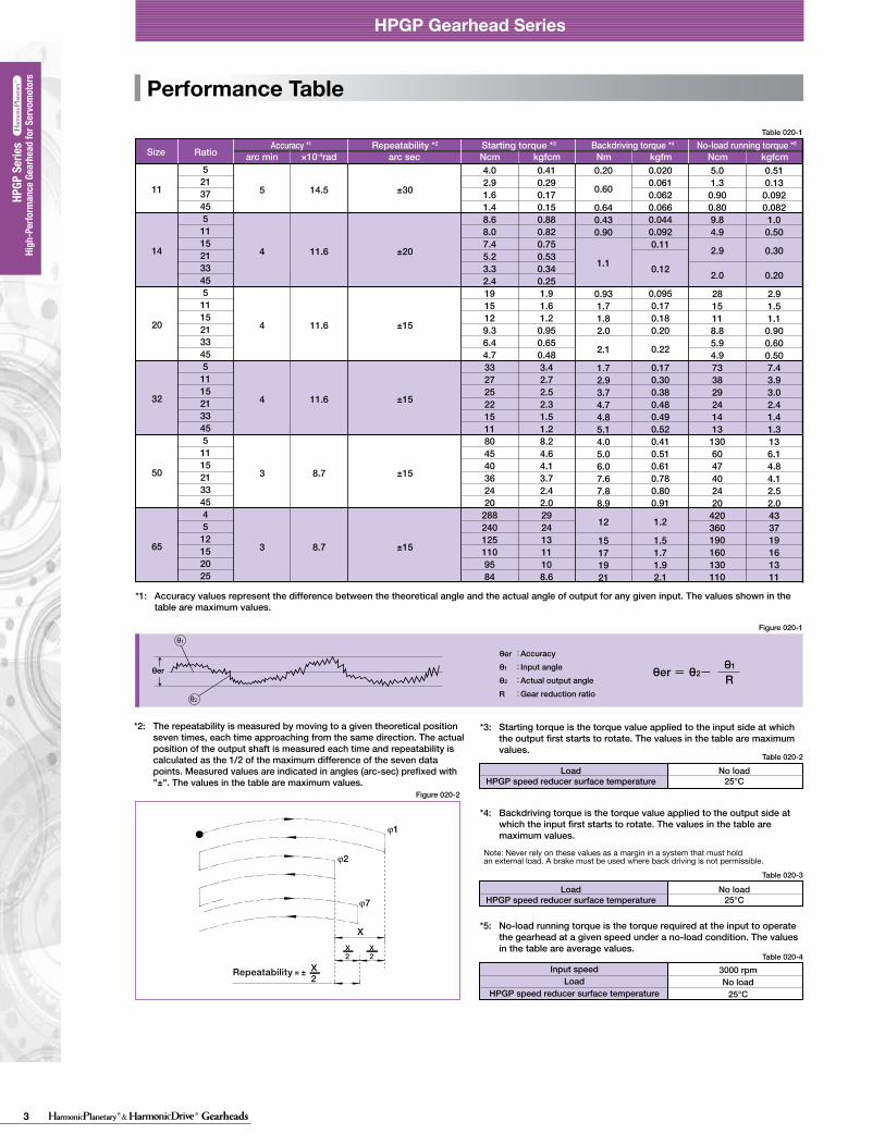
Size RatioAccuracy *1 Repeatability *2 Starting torque *3 Backdriving torque *4 No-load running torque *5
*1: Accuracy values represent the difference between the theoretical angle and the actual angle of output for any given input. The values shown in the table are maximum values.
*3: Starting torque is the torque value applied to the input side at which the output first starts to rotate. The values in the table are maximum values.
*4: Backdriving torque is the torque value applied to the output side at which the input first starts to rotate. The values in the table are maximum values.
*5: No-load running torque is the torque required at the input to operate the gearhead at a given speed under a no-load condition. The values in the table are average values.
*2: The repeatability is measured by moving to a given theoretical position seven times, each time approaching from the same direction. The actual position of the output shaft is measured each time and repeatability is calculated as the 1/2 of the maximum difference of the seven data points. Measured values are indicated in angles (arc-sec) prefixed with "±". The values in the table are maximum values.
LoadHPGP speed reducer surface temperature
No load25°C
LoadHPGP speed reducer surface temperature
No load25°C
11
14
20
32
50
65
5213745511152133455111521334551115213345511152133454512152025
6.6 10 12 13 15 20 21 23 27 29 50 59 70 78 72 98 150 160 220 240 200 280 380 450 460 490 620 640 1150 1190 1350 1670 1520 1900
20
56
63
217
650
1850
2180
4500
3000
3000
3000
3000
2000
2000
0.18
0.24
0.54
0.63
1.6
1.9
2.01.94.4
5.1
5.45.113
15
32 7
47* 7
0.14
0.20
0.42
0.51
1.2
1.5
1.61.53.0
3.7
4.03.710
12
22
37
12
13
39 38
39
133 156
142
156 142 400 440
400
440 400
1460
1500
1460
1360 3520
3790
3940 3790 3840
10000
6000
6000
6000
4500
2500
3000
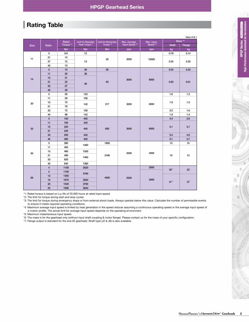
Nm Nm Nm rpm rpm kg kgSize
Rated Torque *1 Shaft Flange
Mass *6Limit for Repeated
Peak Torque *2Max. Average
Input Speed *4Max. Input Speed *5
Limit for Momentary Torque *3Ratio
*1: Rated torque is based on L50 life of 20,000 hours at rated input speed. *2: The limit for torque during start and stop cycles. *3: The limit for torque during emergency stops or from external shock loads. Always operate below this value. Calculate the number of permissible events to ensure it meets required operating conditions. *4: Maximum average input speed is limited by heat generation in the speed reducer assuming a continuous operating speed or the average input speed of a motion profile. The actual limit for average input speed depends on the operating environment. *5: Maximum instantaneous input speed. *6: The mass is for the gearhead only (without input shaft coupling & motor flange). Please contact us for the mass of your specific configuration. *7: Flange output is standard for the size 65 gearhead. Shaft type (J2 & J6) is also available.
θ2
θ1
Note: Never rely on these values as a margin in a system that must hold an external load. A brake must be used where back driving is not permissible.
Table 020-2
Figure 020-2
Table 020-4
3 Gearheads
HPGP Gearhead Series
Dimension Table
Backlash and Tosional Stiffness
A
A
BD
BD
0-TR×0.15
TR×0.15
-TR
TR(4)
(5)(1)
(2)
(3)
θD
TTL
A/B
See Fig. 021-1, Table 021-1, Table 021-2
See Fig. 021-1See Fig. 021-1, Table 021-1 to 2
θ=D+
BA
T-TL
(Unit: mm)
HPGP-11 Outline DimensionsOnly primary dimensions are shown in the drawings below. Refer to the confirmation drawing for detailed dimensions.
Formula 021-1
Table 022-1
28.5°
7.5
0 -0.1
E*4
□40
4 h9
4 h9
Ø10
h7
Ø29
1520
27
Ø5
H7
Ø39
.5Ø
40 h
7
ØA
H7
3
15
H
G5
2.2
B
Ø24
P
1-Ø2.5H7X4PCD18
4-M4×64-Ø3.4
R0.4C0.5
C0.6
C0.5
M3×6
4-D*3
ØF
H7
ØC
Ø46
Ø18
Table 21-1
arc min ×10-4rad arc min ×10-4radD A/B
kgfm/arc min ×100Nm/rad
11
14
20
32
50
65
5213745511152133455111521334551115213345511152133454512152025
3.0
3.0
3.0
3.0
3.0
3.0
8.7
8.7
8.7
8.7
8.7
8.7
2.5
3.0
2.2
2.7
1.5
2.0
1.3
1.7
1.3
1.7
1.3
1.7
7.3
8.7
6.4
7.9
4.4
5.8
3.8
4.9
3.8
4.9
3.8
4.9
0.065
0.14
0.55
2.2
14
38
22
47
180
740
4700
13000
arc min ×10-4rad arc min ×10-4radD A/B
kgfm/arc min ×100Nm/rad
14
20
32
50
65
511152133455111521334551115213345511152133454512152025
1.0
1.0
1.0
1.0
1.0
2.9
2.9
2.9
2.9
2.9
1.1
1.7
0.6
1.1
0.5
1.0
0.5
1.0
0.5
1.0
3.2
4.9
1.7
3.2
1.5
2.9
1.5
2.9
1.5
2.9
0.14
0.55
2.2
14
38
47
180
740
4700
13000
Ø24
Ø40
Detail PCustomer's part
0.4 (Min.0.2)
Clearance0.5 or more
Recommended clearance dimension for customer's part mounted to the output flange(Note)When using a gearhead with an output flange, it is recommended for the customer to design clearance between the part mounted on the output flange and the housing face as shown in the figure on the left. The clearance is needed because the distance between the output flange and the oil seal (non-rotating) is small (min. 0.2mm).
Output flange
2-Hexagon socket head locking screw2-Screw with gasket
018 019
HPGP Gearhead Series
Figure 022-1
HPGP Gearhead Series
■ Gearhead - Standard backlash (BL3) (≤ 3 arc-min)
Torsional stiffnessRatioSizeRatioSize Backlash Torsion angle on one side
at TR X 0.15Torsional stiffness
BacklashTorsion angle on one side at TR X 0.15
■ Gearhead - Reduced backlash (BL1) (≤ 1 arc-min)
With the input of the gear locked in place, a torque applied to the output flange will torsionally deflect in proportion to the applied torque. We generate a torsional stiffness curve by slowly applying torque to the output in the following sequence:(1) Clockwise torque to TR, (2) Return to Zero, (3) Counter-Clockwise torque to -TR, (4) Return to Zero and (5) again Clockwise torque to TR. A loop of (1) > (2) > (3) > (4) > (5) will be drawn as in Fig. 021-1.The torsional stiffness in the region from “0.15 x TR” to “TR” is is calculated using the average value of this slope. The torsional stiffness in the region from “zero torque” to “0.15 x TR” is lower. This is caused by the small amount of backlash plus engagement of the mating parts and loading of the planet gears under the initial torque applied.
Torsional stiffness curveThe vertical distance between points (2) & (4) in Fig. 021-1 is called a hysteresis loss. The hysteresis loss between “Clockwise load torque TR”and “Counter Clockwise load torque - TR” is defined as the backlash of the HPGP series. Backlash of the HPGP series is less than 3 arc-min (1 arc-min is also available).
Backlash (Hysteresis loss)
The method to calculate the total torsion angle (average value) on one side when the speed reducer applies a load in a no-load state.
Calculation of total torsion angle
Torque-torsion angle diagram
Torsion angle
TR: Rated output torqueA/B: Torsional stiffnessD: Torsion on one side at TRX0.15
Hysteresis loss = Backlash
Torque
● Calculation formula
Total torsion angle
Load torque
Torsional stiffness
Torsion angle on one sideat output torque x 0.15 torque
Output torque x 0.15 torque(=TRX0.15)
(Note) The dimension tolerances that are not specified vary depending on the manufacturing method. Please check the confirmation drawing or contact us for dimension tolerances not shown on the drawing above.
High
-Per
form
ance
Gea
rhea
d fo
r Ser
vom
otor
s
High
-Per
form
ance
Gea
rhea
d fo
r Ser
vom
otor
s HP
GP S
eries
HPGP
Ser
ies
11 not available
Mass (kg) *2
Shaft
B
1 20 50 4 28 70 5 8 17.5 26 0.34 0.30
A (H7) C GF (H7)FlangeMin. Max. Max. Min. Max. Min. Max. Min. Max.
54.5
H *1
TypicalFlange
Type I
1 20 50 4 28 70 5 8 17.5 26 0.40 0.3663.5Type I
SingleStage
TwoStage
Coupling
Refer to the confirmation drawing for detailed dimensions. Dimensions of typical products are shown. Please contact us for other mounting options if the configurations shown above are not suitable for your particular motor. *1 May vary depending on motor interface dimensions. *2 The mass will vary slightly depending on the ratio and on the inside diameter of the input shaft coupling.*3 Tapped hole for motor mounting screw.*4 E dimension is dependent on motor selection.
Moment of Inertia Table 022-2
5
0.006
21
0.004
37
0.0027
45
0.00251
CouplingRatio
HPGP 11
(Unit: mm)Table 021-2
Figure 021-1
(10-4 kgm2)
Rating Table
θer :θ1 :θ2 : R :
θer = θ2- Rθ1θer
ϕ1
ϕ2
ϕ7
XX2
X2
X2
11
14
20
32
50
65
5213745511152133455111521334551115213345511152133454512152025
4.02.91.61.48.68.07.45.23.32.41915129.36.44.7332725221511804540362420
2882401251109584
0.410.290.170.150.880.820.750.530.340.251.91.61.2
0.950.650.483.42.72.52.31.51.28.24.64.13.72.42.029241311108.6
0.20
0.60
0.640.430.90
1.1
0.931.71.82.0
2.1
1.72.93.74.74.85.14.05.06.07.67.88.9
12
15171921
0.0200.0610.0620.0660.0440.0920.11
0.12
0.0950.170.180.20
0.22
0.170.300.380.480.490.520.410.510.610.780.800.91
1.2
1.51.71.92.1
5.01.3
0.900.809.84.9
2.9
2.0
2815118.85.94.9733829241413
1306047402420
420360190160130110
0.510.130.0920.082
1.00.50
0.30
0.20
2.91.51.10.900.600.507.43.93.02.41.41.3136.14.84.12.52.0433719161311
5
4
4
4
3
3
14.5
11.6
11.6
11.6
8.7
8.7
±30
±20
±15
±15
±15
±15
Performance TableTable 020-1Table 019-1
Figure 020-1
Table 020-3
Accuracy Input angleActual output angleGear reduction ratio
Repeatability = ± Input speedLoad
HPGP speed reducer surface temperature
3000 rpmNo load
25°C
arc min ×10-4rad arc sec Ncm kgfcm Nm kgfm Ncm kgfcm
016 017
HPGP Gearhead Series HPGP Gearhead Series
High
-per
form
ance
Gea
r Hea
ds fo
r Ser
vo M
otor
s se
ries
HPG
P se
ries
High
-per
form
ance
Gea
r Hea
ds fo
r Ser
vo M
otor
s se
ries
HPG
ser
ies
High
-per
form
ance
Gea
r Hea
ds fo
r Ser
vo M
otor
s se
ries
CSG
-GH
ser
ies
High
-per
form
ance
Gea
r Hea
ds fo
r Ser
vo M
otor
s se
ries
CSF
-GH
ser
ies
High
-per
form
ance
Gea
r Hea
ds fo
r Ser
vo M
otor
s se
ries
HPG
serie
s (Or
thog
onal
Shaf
t Typ
e)
High
-per
form
ance
Gea
r Hea
ds fo
r Ser
vo M
otor
s se
ries
HPG
P se
ries
High
-per
form
ance
Gea
r Hea
ds fo
r Ser
vo M
otor
s se
ries
HPG
ser
ies
High
-per
form
ance
Gea
r Hea
ds fo
r Ser
vo M
otor
s se
ries
CSG
-GH
ser
ies
High
-per
form
ance
Gea
r Hea
ds fo
r Ser
vo M
otor
s ser
iesC
SF-G
H s
erie
sHi
gh-p
erfo
rman
ce G
ear H
eads
for S
ervo
Mot
ors
serie
sHP
G se
ries (
Orth
ogon
al Sh
aft T
ype)
Size RatioAccuracy *1 Repeatability *2 Starting torque *3 Backdriving torque *4 No-load running torque *5
*1: Accuracy values represent the difference between the theoretical angle and the actual angle of output for any given input. The values shown in the table are maximum values.
*3: Starting torque is the torque value applied to the input side at which the output first starts to rotate. The values in the table are maximum values.
*4: Backdriving torque is the torque value applied to the output side at which the input first starts to rotate. The values in the table are maximum values.
*5: No-load running torque is the torque required at the input to operate the gearhead at a given speed under a no-load condition. The values in the table are average values.
*2: The repeatability is measured by moving to a given theoretical position seven times, each time approaching from the same direction. The actual position of the output shaft is measured each time and repeatability is calculated as the 1/2 of the maximum difference of the seven data points. Measured values are indicated in angles (arc-sec) prefixed with "±". The values in the table are maximum values.
LoadHPGP speed reducer surface temperature
No load25°C
LoadHPGP speed reducer surface temperature
No load25°C
11
14
20
32
50
65
5213745511152133455111521334551115213345511152133454512152025
6.6 10 12 13 15 20 21 23 27 29 50 59 70 78 72 98 150 160 220 240 200 280 380 450 460 490 620 640 1150 1190 1350 1670 1520 1900
20
56
63
217
650
1850
2180
4500
3000
3000
3000
3000
2000
2000
0.18
0.24
0.54
0.63
1.6
1.9
2.01.94.4
5.1
5.45.113
15
32 7
47* 7
0.14
0.20
0.42
0.51
1.2
1.5
1.61.53.0
3.7
4.03.710
12
22
37
12
13
39 38
39
133 156
142
156 142 400 440
400
440 400
1460
1500
1460
1360 3520
3790
3940 3790 3840
10000
6000
6000
6000
4500
2500
3000
Nm Nm Nm rpm rpm kg kgSize
Rated Torque *1 Shaft Flange
Mass *6Limit for Repeated
Peak Torque *2Max. Average
Input Speed *4Max. Input Speed *5
Limit for Momentary Torque *3Ratio
*1: Rated torque is based on L50 life of 20,000 hours at rated input speed. *2: The limit for torque during start and stop cycles. *3: The limit for torque during emergency stops or from external shock loads. Always operate below this value. Calculate the number of permissible events to ensure it meets required operating conditions. *4: Maximum average input speed is limited by heat generation in the speed reducer assuming a continuous operating speed or the average input speed of a motion profile. The actual limit for average input speed depends on the operating environment. *5: Maximum instantaneous input speed. *6: The mass is for the gearhead only (without input shaft coupling & motor flange). Please contact us for the mass of your specific configuration. *7: Flange output is standard for the size 65 gearhead. Shaft type (J2 & J6) is also available.
θ2
θ1
Note: Never rely on these values as a margin in a system that must hold an external load. A brake must be used where back driving is not permissible.
Table 020-2
Figure 020-2
Table 020-4
4Gearheads
HPGP Gearhead Series
Dimension Table
Backlash and Tosional Stiffness
A
A
BD
BD
0-TR×0.15
TR×0.15
-TR
TR(4)
(5)(1)
(2)
(3)
θD
TTL
A/B
See Fig. 021-1, Table 021-1, Table 021-2
See Fig. 021-1See Fig. 021-1, Table 021-1 to 2
θ=D+
BA
T-TL
(Unit: mm)
HPGP-11 Outline DimensionsOnly primary dimensions are shown in the drawings below. Refer to the confirmation drawing for detailed dimensions.
Formula 021-1
Table 022-1
28.5°
7.5
0 -0.1
E*4
□40
4 h9
4 h9
Ø10
h7
Ø29
1520
27
Ø5
H7
Ø39
.5Ø
40 h
7
ØA
H7
3
15
H
G5
2.2
BØ
24
P
1-Ø2.5H7X4PCD18
4-M4×64-Ø3.4
R0.4C0.5
C0.6
C0.5
M3×6
4-D*3
ØF
H7
ØC
Ø46
Ø18
Table 21-1
arc min ×10-4rad arc min ×10-4radD A/B
kgfm/arc min ×100Nm/rad
11
14
20
32
50
65
5213745511152133455111521334551115213345511152133454512152025
3.0
3.0
3.0
3.0
3.0
3.0
8.7
8.7
8.7
8.7
8.7
8.7
2.5
3.0
2.2
2.7
1.5
2.0
1.3
1.7
1.3
1.7
1.3
1.7
7.3
8.7
6.4
7.9
4.4
5.8
3.8
4.9
3.8
4.9
3.8
4.9
0.065
0.14
0.55
2.2
14
38
22
47
180
740
4700
13000
arc min ×10-4rad arc min ×10-4radD A/B
kgfm/arc min ×100Nm/rad
14
20
32
50
65
511152133455111521334551115213345511152133454512152025
1.0
1.0
1.0
1.0
1.0
2.9
2.9
2.9
2.9
2.9
1.1
1.7
0.6
1.1
0.5
1.0
0.5
1.0
0.5
1.0
3.2
4.9
1.7
3.2
1.5
2.9
1.5
2.9
1.5
2.9
0.14
0.55
2.2
14
38
47
180
740
4700
13000
Ø24
Ø40
Detail PCustomer's part
0.4 (Min.0.2)
Clearance0.5 or more
Recommended clearance dimension for customer's part mounted to the output flange(Note)When using a gearhead with an output flange, it is recommended for the customer to design clearance between the part mounted on the output flange and the housing face as shown in the figure on the left. The clearance is needed because the distance between the output flange and the oil seal (non-rotating) is small (min. 0.2mm).
Output flange
2-Hexagon socket head locking screw2-Screw with gasket
018 019
HPGP Gearhead Series
Figure 022-1
HPGP Gearhead Series
■ Gearhead - Standard backlash (BL3) (≤ 3 arc-min)
Torsional stiffnessRatioSizeRatioSize Backlash Torsion angle on one side
at TR X 0.15Torsional stiffness
BacklashTorsion angle on one side at TR X 0.15
■ Gearhead - Reduced backlash (BL1) (≤ 1 arc-min)
With the input of the gear locked in place, a torque applied to the output flange will torsionally deflect in proportion to the applied torque. We generate a torsional stiffness curve by slowly applying torque to the output in the following sequence:(1) Clockwise torque to TR, (2) Return to Zero, (3) Counter-Clockwise torque to -TR, (4) Return to Zero and (5) again Clockwise torque to TR. A loop of (1) > (2) > (3) > (4) > (5) will be drawn as in Fig. 021-1.The torsional stiffness in the region from “0.15 x TR” to “TR” is is calculated using the average value of this slope. The torsional stiffness in the region from “zero torque” to “0.15 x TR” is lower. This is caused by the small amount of backlash plus engagement of the mating parts and loading of the planet gears under the initial torque applied.
Torsional stiffness curveThe vertical distance between points (2) & (4) in Fig. 021-1 is called a hysteresis loss. The hysteresis loss between “Clockwise load torque TR”and “Counter Clockwise load torque - TR” is defined as the backlash of the HPGP series. Backlash of the HPGP series is less than 3 arc-min (1 arc-min is also available).
Backlash (Hysteresis loss)
The method to calculate the total torsion angle (average value) on one side when the speed reducer applies a load in a no-load state.
Calculation of total torsion angle
Torque-torsion angle diagram
Torsion angle
TR: Rated output torqueA/B: Torsional stiffnessD: Torsion on one side at TRX0.15
Hysteresis loss = Backlash
Torque
● Calculation formula
Total torsion angle
Load torque
Torsional stiffness
Torsion angle on one sideat output torque x 0.15 torque
Output torque x 0.15 torque(=TRX0.15)
(Note) The dimension tolerances that are not specified vary depending on the manufacturing method. Please check the confirmation drawing or contact us for dimension tolerances not shown on the drawing above.
High
-Per
form
ance
Gea
rhea
d fo
r Ser
vom
otor
s
High
-Per
form
ance
Gea
rhea
d fo
r Ser
vom
otor
s HP
GP S
eries
HPGP
Ser
ies
11 not available
Mass (kg) *2
Shaft
B
1 20 50 4 28 70 5 8 17.5 26 0.34 0.30
A (H7) C GF (H7)FlangeMin. Max. Max. Min. Max. Min. Max. Min. Max.
54.5
H *1
TypicalFlange
Type I
1 20 50 4 28 70 5 8 17.5 26 0.40 0.3663.5Type I
SingleStage
TwoStage
Coupling
Refer to the confirmation drawing for detailed dimensions. Dimensions of typical products are shown. Please contact us for other mounting options if the configurations shown above are not suitable for your particular motor. *1 May vary depending on motor interface dimensions. *2 The mass will vary slightly depending on the ratio and on the inside diameter of the input shaft coupling.*3 Tapped hole for motor mounting screw.*4 E dimension is dependent on motor selection.
Moment of Inertia Table 022-2
5
0.006
21
0.004
37
0.0027
45
0.00251
CouplingRatio
HPGP 11
(Unit: mm)Table 021-2
Figure 021-1
(10-4 kgm2)
Dimension Table
Backlash and Tosional Stiffness
A
A
BD
BD
0-TR×0.15
TR×0.15
-TR
TR(4)
(5)(1)
(2)
(3)
θD
TTL
A/B
See Fig. 021-1, Table 021-1, Table 021-2
See Fig. 021-1See Fig. 021-1, Table 021-1 to 2
θ=D+
BA
T-TL
(Unit: mm)
HPGP-11 Outline DimensionsOnly primary dimensions are shown in the drawings below. Refer to the confirmation drawing for detailed dimensions.
Formula 021-1
Table 022-1
28.5°
7.5
0 -0.1
E*4
□40
4 h9
4 h9
Ø10
h7
Ø29
1520
27
Ø5
H7
Ø39
.5Ø
40 h
7
ØA
H7
3
15
H
G5
2.2
B
Ø24
P
1-Ø2.5H7X4PCD18
4-M4×64-Ø3.4
R0.4C0.5
C0.6
C0.5
M3×6
4-D*3
ØF
H7
ØC
Ø46
Ø18
Table 21-1
arc min ×10-4rad arc min ×10-4radD A/B
kgfm/arc min ×100Nm/rad
11
14
20
32
50
65
5213745511152133455111521334551115213345511152133454512152025
3.0
3.0
3.0
3.0
3.0
3.0
8.7
8.7
8.7
8.7
8.7
8.7
2.5
3.0
2.2
2.7
1.5
2.0
1.3
1.7
1.3
1.7
1.3
1.7
7.3
8.7
6.4
7.9
4.4
5.8
3.8
4.9
3.8
4.9
3.8
4.9
0.065
0.14
0.55
2.2
14
38
22
47
180
740
4700
13000
arc min ×10-4rad arc min ×10-4radD A/B
kgfm/arc min ×100Nm/rad
14
20
32
50
65
511152133455111521334551115213345511152133454512152025
1.0
1.0
1.0
1.0
1.0
2.9
2.9
2.9
2.9
2.9
1.1
1.7
0.6
1.1
0.5
1.0
0.5
1.0
0.5
1.0
3.2
4.9
1.7
3.2
1.5
2.9
1.5
2.9
1.5
2.9
0.14
0.55
2.2
14
38
47
180
740
4700
13000
Ø24
Ø40
Detail PCustomer's part
0.4 (Min.0.2)
Clearance0.5 or more
Recommended clearance dimension for customer's part mounted to the output flange(Note)When using a gearhead with an output flange, it is recommended for the customer to design clearance between the part mounted on the output flange and the housing face as shown in the figure on the left. The clearance is needed because the distance between the output flange and the oil seal (non-rotating) is small (min. 0.2mm).
Output flange
2-Hexagon socket head locking screw2-Screw with gasket
018 019
HPGP Gearhead Series
Figure 022-1
HPGP Gearhead Series
■ Gearhead - Standard backlash (BL3) (≤ 3 arc-min)
Torsional stiffnessRatioSizeRatioSize Backlash Torsion angle on one side
at TR X 0.15Torsional stiffness
BacklashTorsion angle on one side at TR X 0.15
■ Gearhead - Reduced backlash (BL1) (≤ 1 arc-min)
With the input of the gear locked in place, a torque applied to the output flange will torsionally deflect in proportion to the applied torque. We generate a torsional stiffness curve by slowly applying torque to the output in the following sequence:(1) Clockwise torque to TR, (2) Return to Zero, (3) Counter-Clockwise torque to -TR, (4) Return to Zero and (5) again Clockwise torque to TR. A loop of (1) > (2) > (3) > (4) > (5) will be drawn as in Fig. 021-1.The torsional stiffness in the region from “0.15 x TR” to “TR” is is calculated using the average value of this slope. The torsional stiffness in the region from “zero torque” to “0.15 x TR” is lower. This is caused by the small amount of backlash plus engagement of the mating parts and loading of the planet gears under the initial torque applied.
Torsional stiffness curveThe vertical distance between points (2) & (4) in Fig. 021-1 is called a hysteresis loss. The hysteresis loss between “Clockwise load torque TR”and “Counter Clockwise load torque - TR” is defined as the backlash of the HPGP series. Backlash of the HPGP series is less than 3 arc-min (1 arc-min is also available).
Backlash (Hysteresis loss)
The method to calculate the total torsion angle (average value) on one side when the speed reducer applies a load in a no-load state.
Calculation of total torsion angle
Torque-torsion angle diagram
Torsion angle
TR: Rated output torqueA/B: Torsional stiffnessD: Torsion on one side at TRX0.15
Hysteresis loss = Backlash
Torque
● Calculation formula
Total torsion angle
Load torque
Torsional stiffness
Torsion angle on one sideat output torque x 0.15 torque
Output torque x 0.15 torque(=TRX0.15)
(Note) The dimension tolerances that are not specified vary depending on the manufacturing method. Please check the confirmation drawing or contact us for dimension tolerances not shown on the drawing above.
High
-Per
form
ance
Gea
rhea
d fo
r Ser
vom
otor
s
High
-Per
form
ance
Gea
rhea
d fo
r Ser
vom
otor
s HP
GP S
eries
HPGP
Ser
ies
11 not available
Mass (kg) *2
Shaft
B
1 20 50 4 28 70 5 8 17.5 26 0.34 0.30
A (H7) C GF (H7)FlangeMin. Max. Max. Min. Max. Min. Max. Min. Max.
54.5
H *1
TypicalFlange
Type I
1 20 50 4 28 70 5 8 17.5 26 0.40 0.3663.5Type I
SingleStage
TwoStage
Coupling
Refer to the confirmation drawing for detailed dimensions. Dimensions of typical products are shown. Please contact us for other mounting options if the configurations shown above are not suitable for your particular motor. *1 May vary depending on motor interface dimensions. *2 The mass will vary slightly depending on the ratio and on the inside diameter of the input shaft coupling.*3 Tapped hole for motor mounting screw.*4 E dimension is dependent on motor selection.
Moment of Inertia Table 022-2
5
0.006
21
0.004
37
0.0027
45
0.00251
CouplingRatio
HPGP 11
(Unit: mm)Table 021-2
Figure 021-1
(10-4 kgm2)
5 Gearheads
HPGP Gearhead Series
Dimension Table
Backlash and Tosional Stiffness
A
A
BD
BD
0-TR×0.15
TR×0.15
-TR
TR(4)
(5)(1)
(2)
(3)
θD
TTL
A/B
See Fig. 021-1, Table 021-1, Table 021-2
See Fig. 021-1See Fig. 021-1, Table 021-1 to 2
θ=D+
BA
T-TL
(Unit: mm)
HPGP-11 Outline DimensionsOnly primary dimensions are shown in the drawings below. Refer to the confirmation drawing for detailed dimensions.
Formula 021-1
Table 022-1
28.5°
7.5
0 -0.1
E*4
□40
4 h9
4 h9
Ø10
h7
Ø29
1520
27
Ø5
H7
Ø39
.5Ø
40 h
7
ØA
H7
3
15
H
G5
2.2
B
Ø24
P
1-Ø2.5H7X4PCD18
4-M4×64-Ø3.4
R0.4C0.5
C0.6
C0.5
M3×6
4-D*3
ØF
H7
ØC
Ø46
Ø18
Table 21-1
arc min ×10-4rad arc min ×10-4radD A/B
kgfm/arc min ×100Nm/rad
11
14
20
32
50
65
5213745511152133455111521334551115213345511152133454512152025
3.0
3.0
3.0
3.0
3.0
3.0
8.7
8.7
8.7
8.7
8.7
8.7
2.5
3.0
2.2
2.7
1.5
2.0
1.3
1.7
1.3
1.7
1.3
1.7
7.3
8.7
6.4
7.9
4.4
5.8
3.8
4.9
3.8
4.9
3.8
4.9
0.065
0.14
0.55
2.2
14
38
22
47
180
740
4700
13000
arc min ×10-4rad arc min ×10-4radD A/B
kgfm/arc min ×100Nm/rad
14
20
32
50
65
511152133455111521334551115213345511152133454512152025
1.0
1.0
1.0
1.0
1.0
2.9
2.9
2.9
2.9
2.9
1.1
1.7
0.6
1.1
0.5
1.0
0.5
1.0
0.5
1.0
3.2
4.9
1.7
3.2
1.5
2.9
1.5
2.9
1.5
2.9
0.14
0.55
2.2
14
38
47
180
740
4700
13000
Ø24
Ø40
Detail PCustomer's part
0.4 (Min.0.2)
Clearance0.5 or more
Recommended clearance dimension for customer's part mounted to the output flange(Note)When using a gearhead with an output flange, it is recommended for the customer to design clearance between the part mounted on the output flange and the housing face as shown in the figure on the left. The clearance is needed because the distance between the output flange and the oil seal (non-rotating) is small (min. 0.2mm).
Output flange
2-Hexagon socket head locking screw2-Screw with gasket
018 019
HPGP Gearhead Series
Figure 022-1
HPGP Gearhead Series
■ Gearhead - Standard backlash (BL3) (≤ 3 arc-min)
Torsional stiffnessRatioSizeRatioSize Backlash Torsion angle on one side
at TR X 0.15Torsional stiffness
BacklashTorsion angle on one side at TR X 0.15
■ Gearhead - Reduced backlash (BL1) (≤ 1 arc-min)
With the input of the gear locked in place, a torque applied to the output flange will torsionally deflect in proportion to the applied torque. We generate a torsional stiffness curve by slowly applying torque to the output in the following sequence:(1) Clockwise torque to TR, (2) Return to Zero, (3) Counter-Clockwise torque to -TR, (4) Return to Zero and (5) again Clockwise torque to TR. A loop of (1) > (2) > (3) > (4) > (5) will be drawn as in Fig. 021-1.The torsional stiffness in the region from “0.15 x TR” to “TR” is is calculated using the average value of this slope. The torsional stiffness in the region from “zero torque” to “0.15 x TR” is lower. This is caused by the small amount of backlash plus engagement of the mating parts and loading of the planet gears under the initial torque applied.
Torsional stiffness curveThe vertical distance between points (2) & (4) in Fig. 021-1 is called a hysteresis loss. The hysteresis loss between “Clockwise load torque TR”and “Counter Clockwise load torque - TR” is defined as the backlash of the HPGP series. Backlash of the HPGP series is less than 3 arc-min (1 arc-min is also available).
Backlash (Hysteresis loss)
The method to calculate the total torsion angle (average value) on one side when the speed reducer applies a load in a no-load state.
Calculation of total torsion angle
Torque-torsion angle diagram
Torsion angle
TR: Rated output torqueA/B: Torsional stiffnessD: Torsion on one side at TRX0.15
Hysteresis loss = Backlash
Torque
● Calculation formula
Total torsion angle
Load torque
Torsional stiffness
Torsion angle on one sideat output torque x 0.15 torque
Output torque x 0.15 torque(=TRX0.15)
(Note) The dimension tolerances that are not specified vary depending on the manufacturing method. Please check the confirmation drawing or contact us for dimension tolerances not shown on the drawing above.
High
-Per
form
ance
Gea
rhea
d fo
r Ser
vom
otor
s
High
-Per
form
ance
Gea
rhea
d fo
r Ser
vom
otor
s HP
GP S
eries
HPGP
Ser
ies
11 not available
Mass (kg) *2
Shaft
B
1 20 50 4 28 70 5 8 17.5 26 0.34 0.30
A (H7) C GF (H7)FlangeMin. Max. Max. Min. Max. Min. Max. Min. Max.
54.5
H *1
TypicalFlange
Type I
1 20 50 4 28 70 5 8 17.5 26 0.40 0.3663.5Type I
SingleStage
TwoStage
Coupling
Refer to the confirmation drawing for detailed dimensions. Dimensions of typical products are shown. Please contact us for other mounting options if the configurations shown above are not suitable for your particular motor. *1 May vary depending on motor interface dimensions. *2 The mass will vary slightly depending on the ratio and on the inside diameter of the input shaft coupling.*3 Tapped hole for motor mounting screw.*4 E dimension is dependent on motor selection.
Moment of Inertia Table 022-2
5
0.006
21
0.004
37
0.0027
45
0.00251
CouplingRatio
HPGP 11
(Unit: mm)Table 021-2
Figure 021-1
(10-4 kgm2)
Dimension Table
Backlash and Tosional Stiffness
A
A
BD
BD
0-TR×0.15
TR×0.15
-TR
TR(4)
(5)(1)
(2)
(3)
θD
TTL
A/B
See Fig. 021-1, Table 021-1, Table 021-2
See Fig. 021-1See Fig. 021-1, Table 021-1 to 2
θ=D+
BA
T-TL
(Unit: mm)
HPGP-11 Outline DimensionsOnly primary dimensions are shown in the drawings below. Refer to the confirmation drawing for detailed dimensions.
Formula 021-1
Table 022-1
28.5°
7.5
0 -0.1
E*4
□40
4 h9
4 h9
Ø10
h7
Ø29
1520
27Ø
5 H
7
Ø39
.5Ø
40 h
7
ØA
H7
3
15
H
G5
2.2
B
Ø24
P
1-Ø2.5H7X4PCD18
4-M4×64-Ø3.4
R0.4C0.5
C0.6
C0.5
M3×6
4-D*3
ØF
H7
ØC
Ø46
Ø18
Table 21-1
arc min ×10-4rad arc min ×10-4radD A/B
kgfm/arc min ×100Nm/rad
11
14
20
32
50
65
5213745511152133455111521334551115213345511152133454512152025
3.0
3.0
3.0
3.0
3.0
3.0
8.7
8.7
8.7
8.7
8.7
8.7
2.5
3.0
2.2
2.7
1.5
2.0
1.3
1.7
1.3
1.7
1.3
1.7
7.3
8.7
6.4
7.9
4.4
5.8
3.8
4.9
3.8
4.9
3.8
4.9
0.065
0.14
0.55
2.2
14
38
22
47
180
740
4700
13000
arc min ×10-4rad arc min ×10-4radD A/B
kgfm/arc min ×100Nm/rad
14
20
32
50
65
511152133455111521334551115213345511152133454512152025
1.0
1.0
1.0
1.0
1.0
2.9
2.9
2.9
2.9
2.9
1.1
1.7
0.6
1.1
0.5
1.0
0.5
1.0
0.5
1.0
3.2
4.9
1.7
3.2
1.5
2.9
1.5
2.9
1.5
2.9
0.14
0.55
2.2
14
38
47
180
740
4700
13000
Ø24
Ø40
Detail PCustomer's part
0.4 (Min.0.2)
Clearance0.5 or more
Recommended clearance dimension for customer's part mounted to the output flange(Note)When using a gearhead with an output flange, it is recommended for the customer to design clearance between the part mounted on the output flange and the housing face as shown in the figure on the left. The clearance is needed because the distance between the output flange and the oil seal (non-rotating) is small (min. 0.2mm).
Output flange
2-Hexagon socket head locking screw2-Screw with gasket
018 019
HPGP Gearhead Series
Figure 022-1
HPGP Gearhead Series
■ Gearhead - Standard backlash (BL3) (≤ 3 arc-min)
Torsional stiffnessRatioSizeRatioSize Backlash Torsion angle on one side
at TR X 0.15Torsional stiffness
BacklashTorsion angle on one side at TR X 0.15
■ Gearhead - Reduced backlash (BL1) (≤ 1 arc-min)
With the input of the gear locked in place, a torque applied to the output flange will torsionally deflect in proportion to the applied torque. We generate a torsional stiffness curve by slowly applying torque to the output in the following sequence:(1) Clockwise torque to TR, (2) Return to Zero, (3) Counter-Clockwise torque to -TR, (4) Return to Zero and (5) again Clockwise torque to TR. A loop of (1) > (2) > (3) > (4) > (5) will be drawn as in Fig. 021-1.The torsional stiffness in the region from “0.15 x TR” to “TR” is is calculated using the average value of this slope. The torsional stiffness in the region from “zero torque” to “0.15 x TR” is lower. This is caused by the small amount of backlash plus engagement of the mating parts and loading of the planet gears under the initial torque applied.
Torsional stiffness curveThe vertical distance between points (2) & (4) in Fig. 021-1 is called a hysteresis loss. The hysteresis loss between “Clockwise load torque TR”and “Counter Clockwise load torque - TR” is defined as the backlash of the HPGP series. Backlash of the HPGP series is less than 3 arc-min (1 arc-min is also available).
Backlash (Hysteresis loss)
The method to calculate the total torsion angle (average value) on one side when the speed reducer applies a load in a no-load state.
Calculation of total torsion angle
Torque-torsion angle diagram
Torsion angle
TR: Rated output torqueA/B: Torsional stiffnessD: Torsion on one side at TRX0.15
Hysteresis loss = Backlash
Torque
● Calculation formula
Total torsion angle
Load torque
Torsional stiffness
Torsion angle on one sideat output torque x 0.15 torque
Output torque x 0.15 torque(=TRX0.15)
(Note) The dimension tolerances that are not specified vary depending on the manufacturing method. Please check the confirmation drawing or contact us for dimension tolerances not shown on the drawing above.
High
-Per
form
ance
Gea
rhea
d fo
r Ser
vom
otor
s
High
-Per
form
ance
Gea
rhea
d fo
r Ser
vom
otor
s HP
GP S
eries
HPGP
Ser
ies
11 not available
Mass (kg) *2
Shaft
B
1 20 50 4 28 70 5 8 17.5 26 0.34 0.30
A (H7) C GF (H7)FlangeMin. Max. Max. Min. Max. Min. Max. Min. Max.
54.5
H *1
TypicalFlange
Type I
1 20 50 4 28 70 5 8 17.5 26 0.40 0.3663.5Type I
SingleStage
TwoStage
Coupling
Refer to the confirmation drawing for detailed dimensions. Dimensions of typical products are shown. Please contact us for other mounting options if the configurations shown above are not suitable for your particular motor. *1 May vary depending on motor interface dimensions. *2 The mass will vary slightly depending on the ratio and on the inside diameter of the input shaft coupling.*3 Tapped hole for motor mounting screw.*4 E dimension is dependent on motor selection.
Moment of Inertia Table 022-2
5
0.006
21
0.004
37
0.0027
45
0.00251
CouplingRatio
HPGP 11
(Unit: mm)Table 021-2
Figure 021-1
(10-4 kgm2)
6Gearheads
HPGP Gearhead Series
Dimension Table
Backlash and Tosional Stiffness
A
A
BD
BD
0-TR×0.15
TR×0.15
-TR
TR(4)
(5)(1)
(2)
(3)
θD
TTL
A/B
See Fig. 021-1, Table 021-1, Table 021-2
See Fig. 021-1See Fig. 021-1, Table 021-1 to 2
θ=D+
BA
T-TL
(Unit: mm)
HPGP-11 Outline DimensionsOnly primary dimensions are shown in the drawings below. Refer to the confirmation drawing for detailed dimensions.
Formula 021-1
Table 022-1
28.5°
7.5
0 -0.1
E*4
□40
4 h9
4 h9
Ø10
h7
Ø29
1520
27
Ø5
H7
Ø39
.5Ø
40 h
7
ØA
H7
3
15
H
G5
2.2
BØ
24
P
1-Ø2.5H7X4PCD18
4-M4×64-Ø3.4
R0.4C0.5
C0.6
C0.5
M3×6
4-D*3
ØF
H7
ØC
Ø46
Ø18
Table 21-1
arc min ×10-4rad arc min ×10-4radD A/B
kgfm/arc min ×100Nm/rad
11
14
20
32
50
65
5213745511152133455111521334551115213345511152133454512152025
3.0
3.0
3.0
3.0
3.0
3.0
8.7
8.7
8.7
8.7
8.7
8.7
2.5
3.0
2.2
2.7
1.5
2.0
1.3
1.7
1.3
1.7
1.3
1.7
7.3
8.7
6.4
7.9
4.4
5.8
3.8
4.9
3.8
4.9
3.8
4.9
0.065
0.14
0.55
2.2
14
38
22
47
180
740
4700
13000
arc min ×10-4rad arc min ×10-4radD A/B
kgfm/arc min ×100Nm/rad
14
20
32
50
65
511152133455111521334551115213345511152133454512152025
1.0
1.0
1.0
1.0
1.0
2.9
2.9
2.9
2.9
2.9
1.1
1.7
0.6
1.1
0.5
1.0
0.5
1.0
0.5
1.0
3.2
4.9
1.7
3.2
1.5
2.9
1.5
2.9
1.5
2.9
0.14
0.55
2.2
14
38
47
180
740
4700
13000
Ø24
Ø40
Detail PCustomer's part
0.4 (Min.0.2)
Clearance0.5 or more
Recommended clearance dimension for customer's part mounted to the output flange(Note)When using a gearhead with an output flange, it is recommended for the customer to design clearance between the part mounted on the output flange and the housing face as shown in the figure on the left. The clearance is needed because the distance between the output flange and the oil seal (non-rotating) is small (min. 0.2mm).
Output flange
2-Hexagon socket head locking screw2-Screw with gasket
018 019
HPGP Gearhead Series
Figure 022-1
HPGP Gearhead Series
■ Gearhead - Standard backlash (BL3) (≤ 3 arc-min)
Torsional stiffnessRatioSizeRatioSize Backlash Torsion angle on one side
at TR X 0.15Torsional stiffness
BacklashTorsion angle on one side at TR X 0.15
■ Gearhead - Reduced backlash (BL1) (≤ 1 arc-min)
With the input of the gear locked in place, a torque applied to the output flange will torsionally deflect in proportion to the applied torque. We generate a torsional stiffness curve by slowly applying torque to the output in the following sequence:(1) Clockwise torque to TR, (2) Return to Zero, (3) Counter-Clockwise torque to -TR, (4) Return to Zero and (5) again Clockwise torque to TR. A loop of (1) > (2) > (3) > (4) > (5) will be drawn as in Fig. 021-1.The torsional stiffness in the region from “0.15 x TR” to “TR” is is calculated using the average value of this slope. The torsional stiffness in the region from “zero torque” to “0.15 x TR” is lower. This is caused by the small amount of backlash plus engagement of the mating parts and loading of the planet gears under the initial torque applied.
Torsional stiffness curveThe vertical distance between points (2) & (4) in Fig. 021-1 is called a hysteresis loss. The hysteresis loss between “Clockwise load torque TR”and “Counter Clockwise load torque - TR” is defined as the backlash of the HPGP series. Backlash of the HPGP series is less than 3 arc-min (1 arc-min is also available).
Backlash (Hysteresis loss)
The method to calculate the total torsion angle (average value) on one side when the speed reducer applies a load in a no-load state.
Calculation of total torsion angle
Torque-torsion angle diagram
Torsion angle
TR: Rated output torqueA/B: Torsional stiffnessD: Torsion on one side at TRX0.15
Hysteresis loss = Backlash
Torque
● Calculation formula
Total torsion angle
Load torque
Torsional stiffness
Torsion angle on one sideat output torque x 0.15 torque
Output torque x 0.15 torque(=TRX0.15)
(Note) The dimension tolerances that are not specified vary depending on the manufacturing method. Please check the confirmation drawing or contact us for dimension tolerances not shown on the drawing above.
High
-Per
form
ance
Gea
rhea
d fo
r Ser
vom
otor
s
High
-Per
form
ance
Gea
rhea
d fo
r Ser
vom
otor
s HP
GP S
eries
HPGP
Ser
ies
11 not available
Mass (kg) *2
Shaft
B
1 20 50 4 28 70 5 8 17.5 26 0.34 0.30
A (H7) C GF (H7)FlangeMin. Max. Max. Min. Max. Min. Max. Min. Max.
54.5
H *1
TypicalFlange
Type I
1 20 50 4 28 70 5 8 17.5 26 0.40 0.3663.5Type I
SingleStage
TwoStage
Coupling
Refer to the confirmation drawing for detailed dimensions. Dimensions of typical products are shown. Please contact us for other mounting options if the configurations shown above are not suitable for your particular motor. *1 May vary depending on motor interface dimensions. *2 The mass will vary slightly depending on the ratio and on the inside diameter of the input shaft coupling.*3 Tapped hole for motor mounting screw.*4 E dimension is dependent on motor selection.
Moment of Inertia Table 022-2
5
0.006
21
0.004
37
0.0027
45
0.00251
CouplingRatio
HPGP 11
(Unit: mm)Table 021-2
Figure 021-1
(10-4 kgm2)
HPGP-20 Outline Dimensions
Dimension TableDimension Table
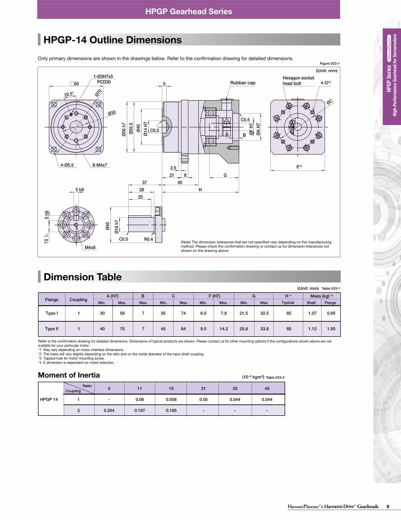
HPGP-14 Outline Dimensions
(Unit: mm)(Unit: mm)
Figure 023-1
Table 023-1
Figure 024-1
Table 024-1
Only primary dimensions are shown in the drawings below. Refer to the confirmation drawing for detailed dimensions. Only primary dimensions are shown in the drawings below. Refer to the confirmation drawing for detailed dimensions.
22.5°
□60 5
2140
H
G82.5
Ø14
H7Ø4
0Ø5
5.5
Ø56
h7
ØA H
7
B
Ø16
h7
Ø40
2528
375 h9
5 h9
13 0 -0
.1
PCD30
4-Ø5.5 8-M4x7
ØF H
7
C0.5
C0.5
Hexagon sockethead boltRubber cap
M4x8
C0.5 R0.4
1-Ø3H7x5
ØCØ70
Ø30
22.5°
53
□90
Ø24
H7Ø5
9Ø8
4Ø8
5 h7
ØF H
7ØA
H7
B
5
277.5
1046
G
H
7 h1
121
0 -0.2
8 h9
Ø25
h7Ø5
9
3642
PCD351-Ø5H7x8
M6x12
4-Ø9 8-M6x10
Rubber cap
C0.5
C0.5
C1 R0.4
Ø45
Ø105
Hexagon sockethead bolt
ØC
020 021
HPGP Gearhead Series HPGP Gearhead Series
High
-per
form
ance
Gea
r Hea
ds fo
r Ser
vo M
otor
s ser
iesHP
GP se
ries
High
-per
form
ance
Gea
r Hea
ds fo
r Ser
vo M
otor
s ser
iesHP
G se
ries
High
-per
form
ance
Gea
r Hea
ds fo
r Ser
vo M
otor
s ser
iesCS
G-GH
serie
sHi
gh-p
erfo
rman
ce G
ear H
eads
for S
ervo
Mot
ors s
eries
CSF-
GH se
ries
High
-per
form
ance
Gea
r Hea
ds fo
r Ser
vo M
otor
s ser
iesHP
G se
ries (
Orth
ogon
al S
haft
Type
)
High
-per
form
ance
Gea
r Hea
ds fo
r Ser
vo M
otor
s ser
iesHP
GP se
ries
High
-per
form
ance
Gea
r Hea
ds fo
r Ser
vo M
otor
s ser
iesHP
G se
ries
High
-per
form
ance
Gea
r Hea
ds fo
r Ser
vo M
otor
s ser
iesCS
G-GH
serie
sHi
gh-p
erfo
rman
ce G
ear H
eads
for S
ervo
Mot
ors s
eries
CSF-
GH se
ries
High
-per
form
ance
Gea
r Hea
ds fo
r Ser
vo M
otor
s ser
iesHP
G se
ries (
Orth
ogon
al S
haft
Type
)
(Note) The dimension tolerances that are not specified vary depending on the manufacturing method. Please check the confirmation drawing or contact us for dimension tolerances not shown on the drawing above.
(Note) The dimension tolerances that are not specified vary depending on the manufacturing method. Please check the confirmation drawing or contact us for dimension tolerances not shown on the drawing above.
Mass (kg) *2
Shaft
B
1 30 58 7 35 74 6.0 7.8 21.5 32.5 1.07 0.95
A (H7) C GF (H7)FlangeMin. Max. Max. Min. Max. Min. Max. Min. Max.
85
H *1
Flange
Type I
1 40 70 7 45 84 9.0 14.2 25.8 33.8 1.12 1.0085Type II
CouplingShaft
B
1 50 72 8 55 80 7.0 19.6 23.0 35.5 3.1 2.7
A (H7) C GF (H7)FlangeMin. Max. Max. Min. Max. Min. Max. Min. Max.
98.0
Flange
Type I
Coupling
1 80 98 10 90 120 7.0 19.6 30.0 42.5 3.3 2.9105.0Type II
3 30 45 10 35 50 7.0 7.8 21.0 31.0 2.6 2.293.5Type III
1 46 70 10 55 96 7.0 19.6 30.0 42.5 3.3 2.9105.0Type IV
1 50 72 8 55 80 7.0 19.6 23.0 35.5 3.1 2.7103.0Type I
-33
Ratio 1 80 98 10 90 120 7.0 19.6 30.0 42.5 3.3 2.9110.0Type II
3 30 45 10 35 50 7.0 7.8 21.0 31.0 2.6 2.298.5Type III
1 46 70 10 55 96 7.0 19.6 30.0 42.5 3.3 2.9103.0Type IV
Typical
Typical
Mass (kg) *2H *1
E*4
4-D*3
E*4
4-D*3
Refer to the confirmation drawing for detailed dimensions. Dimensions of typical products are shown. Please contact us for other mounting options if the configurations shown above are not suitable for your particular motor. *1 May vary depending on motor interface dimensions. *2 The mass will vary slightly depending on the ratio and on the inside diameter of the input shaft coupling.*3 Tapped hole for motor mounting screw.*4 E dimension is dependent on motor selection.
Refer to the confirmation drawing for detailed dimensions. Dimensions of typical products are shown. Please contact us for other mounting options if the configurations shown above are not suitable for your particular motor. *1 May vary depending on motor interface dimensions. *2 The mass will vary slightly depending on the ratio and on the inside diameter of the input shaft coupling.*3 Tapped hole for motor mounting screw.*4 E dimension is dependent on motor selection.
Moment of Inertia Table 023-2
5
-
0.204
11
0.06
0.197
15
0.058
0.195
21
0.05
-
33
0.044
-
45
0.044
-
1
2
CouplingRatio
HPGP 14
Moment of Inertia Table 024-2
5
0.69
-
11
0.62
-
15
0.58
-
21
0.5
0.12
33
0.45
0.071
45
0.45
0.063
1
2
CouplingRatio
HPGP 20
(Unit: mm)(Unit: mm)
(10-4 kgm2)
(10-4 kgm2)
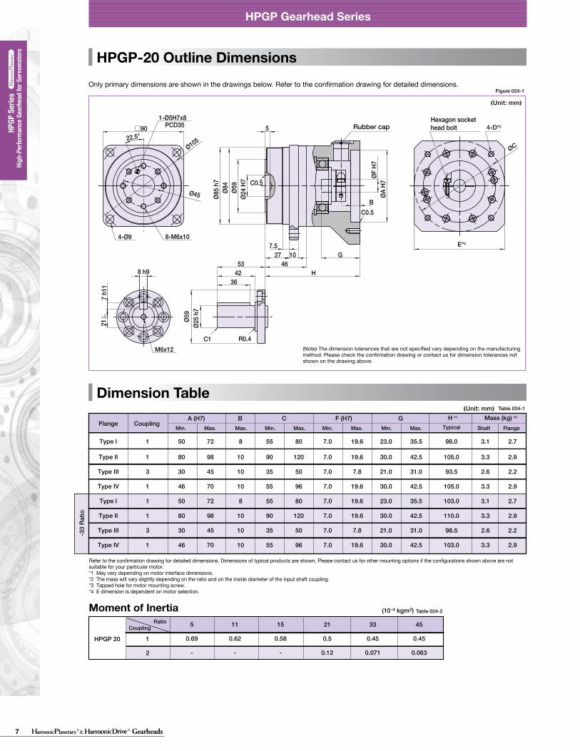
7 Gearheads
HPGP Gearhead Series
Dimension Table
Backlash and Tosional Stiffness
A
A
BD
BD
0-TR×0.15
TR×0.15
-TR
TR(4)
(5)(1)
(2)
(3)
θD
TTL
A/B
See Fig. 021-1, Table 021-1, Table 021-2
See Fig. 021-1See Fig. 021-1, Table 021-1 to 2
θ=D+
BA
T-TL
(Unit: mm)
HPGP-11 Outline DimensionsOnly primary dimensions are shown in the drawings below. Refer to the confirmation drawing for detailed dimensions.
Formula 021-1
Table 022-1
28.5°
7.5
0 -0.1
E*4
□40
4 h9
4 h9
Ø10
h7
Ø29
1520
27
Ø5
H7
Ø39
.5Ø
40 h
7
ØA
H7
3
15
H
G5
2.2
B
Ø24
P
1-Ø2.5H7X4PCD18
4-M4×64-Ø3.4
R0.4C0.5
C0.6
C0.5
M3×6
4-D*3
ØF
H7
ØC
Ø46
Ø18
Table 21-1
arc min ×10-4rad arc min ×10-4radD A/B
kgfm/arc min ×100Nm/rad
11
14
20
32
50
65
5213745511152133455111521334551115213345511152133454512152025
3.0
3.0
3.0
3.0
3.0
3.0
8.7
8.7
8.7
8.7
8.7
8.7
2.5
3.0
2.2
2.7
1.5
2.0
1.3
1.7
1.3
1.7
1.3
1.7
7.3
8.7
6.4
7.9
4.4
5.8
3.8
4.9
3.8
4.9
3.8
4.9
0.065
0.14
0.55
2.2
14
38
22
47
180
740
4700
13000
arc min ×10-4rad arc min ×10-4radD A/B
kgfm/arc min ×100Nm/rad
14
20
32
50
65
511152133455111521334551115213345511152133454512152025
1.0
1.0
1.0
1.0
1.0
2.9
2.9
2.9
2.9
2.9
1.1
1.7
0.6
1.1
0.5
1.0
0.5
1.0
0.5
1.0
3.2
4.9
1.7
3.2
1.5
2.9
1.5
2.9
1.5
2.9
0.14
0.55
2.2
14
38
47
180
740
4700
13000
Ø24
Ø40
Detail PCustomer's part
0.4 (Min.0.2)
Clearance0.5 or more
Recommended clearance dimension for customer's part mounted to the output flange(Note)When using a gearhead with an output flange, it is recommended for the customer to design clearance between the part mounted on the output flange and the housing face as shown in the figure on the left. The clearance is needed because the distance between the output flange and the oil seal (non-rotating) is small (min. 0.2mm).
Output flange
2-Hexagon socket head locking screw2-Screw with gasket
018 019
HPGP Gearhead Series
Figure 022-1
HPGP Gearhead Series
■ Gearhead - Standard backlash (BL3) (≤ 3 arc-min)
Torsional stiffnessRatioSizeRatioSize Backlash Torsion angle on one side
at TR X 0.15Torsional stiffness
BacklashTorsion angle on one side at TR X 0.15
■ Gearhead - Reduced backlash (BL1) (≤ 1 arc-min)
With the input of the gear locked in place, a torque applied to the output flange will torsionally deflect in proportion to the applied torque. We generate a torsional stiffness curve by slowly applying torque to the output in the following sequence:(1) Clockwise torque to TR, (2) Return to Zero, (3) Counter-Clockwise torque to -TR, (4) Return to Zero and (5) again Clockwise torque to TR. A loop of (1) > (2) > (3) > (4) > (5) will be drawn as in Fig. 021-1.The torsional stiffness in the region from “0.15 x TR” to “TR” is is calculated using the average value of this slope. The torsional stiffness in the region from “zero torque” to “0.15 x TR” is lower. This is caused by the small amount of backlash plus engagement of the mating parts and loading of the planet gears under the initial torque applied.
Torsional stiffness curveThe vertical distance between points (2) & (4) in Fig. 021-1 is called a hysteresis loss. The hysteresis loss between “Clockwise load torque TR”and “Counter Clockwise load torque - TR” is defined as the backlash of the HPGP series. Backlash of the HPGP series is less than 3 arc-min (1 arc-min is also available).
Backlash (Hysteresis loss)
The method to calculate the total torsion angle (average value) on one side when the speed reducer applies a load in a no-load state.
Calculation of total torsion angle
Torque-torsion angle diagram
Torsion angle
TR: Rated output torqueA/B: Torsional stiffnessD: Torsion on one side at TRX0.15
Hysteresis loss = Backlash
Torque
● Calculation formula
Total torsion angle
Load torque
Torsional stiffness
Torsion angle on one sideat output torque x 0.15 torque
Output torque x 0.15 torque(=TRX0.15)
(Note) The dimension tolerances that are not specified vary depending on the manufacturing method. Please check the confirmation drawing or contact us for dimension tolerances not shown on the drawing above.
High
-Per
form
ance
Gea
rhea
d fo
r Ser
vom
otor
s
High
-Per
form
ance
Gea
rhea
d fo
r Ser
vom
otor
s HP
GP S
eries
HPGP
Ser
ies
11 not available
Mass (kg) *2
Shaft
B
1 20 50 4 28 70 5 8 17.5 26 0.34 0.30
A (H7) C GF (H7)FlangeMin. Max. Max. Min. Max. Min. Max. Min. Max.
54.5
H *1
TypicalFlange
Type I
1 20 50 4 28 70 5 8 17.5 26 0.40 0.3663.5Type I
SingleStage
TwoStage
Coupling
Refer to the confirmation drawing for detailed dimensions. Dimensions of typical products are shown. Please contact us for other mounting options if the configurations shown above are not suitable for your particular motor. *1 May vary depending on motor interface dimensions. *2 The mass will vary slightly depending on the ratio and on the inside diameter of the input shaft coupling.*3 Tapped hole for motor mounting screw.*4 E dimension is dependent on motor selection.
Moment of Inertia Table 022-2
5
0.006
21
0.004
37
0.0027
45
0.00251
CouplingRatio
HPGP 11
(Unit: mm)Table 021-2
Figure 021-1
(10-4 kgm2)
HPGP-20 Outline Dimensions
Dimension TableDimension Table
HPGP-14 Outline Dimensions
(Unit: mm)(Unit: mm)
Figure 023-1
Table 023-1
Figure 024-1
Table 024-1
Only primary dimensions are shown in the drawings below. Refer to the confirmation drawing for detailed dimensions. Only primary dimensions are shown in the drawings below. Refer to the confirmation drawing for detailed dimensions.
22.5°
□60 5
2140
H
G82.5
Ø14
H7Ø4
0Ø5
5.5
Ø56
h7
ØA H
7
B
Ø16
h7
Ø40
2528
375 h9
5 h9
13 0 -0
.1
PCD30
4-Ø5.5 8-M4x7
ØF H
7
C0.5
C0.5
Hexagon sockethead boltRubber cap
M4x8
C0.5 R0.4
1-Ø3H7x5
ØC
Ø70
Ø30
22.5°
53
□90
Ø24
H7Ø5
9Ø8
4Ø8
5 h7
ØF H
7ØA
H7
B
5
277.5
1046
G
H
7 h1
121
0 -0.2
8 h9
Ø25
h7Ø5
9
3642
PCD351-Ø5H7x8
M6x12
4-Ø9 8-M6x10
Rubber cap
C0.5
C0.5
C1 R0.4
Ø45
Ø105
Hexagon sockethead bolt
ØC
020 021
HPGP Gearhead Series HPGP Gearhead Series
High
-per
form
ance
Gea
r Hea
ds fo
r Ser
vo M
otor
s ser
iesHP
GP se
ries
High
-per
form
ance
Gea
r Hea
ds fo
r Ser
vo M
otor
s ser
iesHP
G se
ries
High
-per
form
ance
Gea
r Hea
ds fo
r Ser
vo M
otor
s ser
iesCS
G-GH
serie
sHi
gh-p
erfo
rman
ce G
ear H
eads
for S
ervo
Mot
ors s
eries
CSF-
GH se
ries
High
-per
form
ance
Gea
r Hea
ds fo
r Ser
vo M
otor
s ser
iesHP
G se
ries (
Orth
ogon
al S
haft
Type
)
High
-per
form
ance
Gea
r Hea
ds fo
r Ser
vo M
otor
s ser
iesHP
GP se
ries
High
-per
form
ance
Gea
r Hea
ds fo
r Ser
vo M
otor
s ser
iesHP
G se
ries
High
-per
form
ance
Gea
r Hea
ds fo
r Ser
vo M
otor
s ser
iesCS
G-GH
serie
sHi
gh-p
erfo
rman
ce G
ear H
eads
for S
ervo
Mot
ors s
eries
CSF-
GH se
ries
High
-per
form
ance
Gea
r Hea
ds fo
r Ser
vo M
otor
s ser
iesHP
G se
ries (
Orth
ogon
al S
haft
Type
)
(Note) The dimension tolerances that are not specified vary depending on the manufacturing method. Please check the confirmation drawing or contact us for dimension tolerances not shown on the drawing above.
(Note) The dimension tolerances that are not specified vary depending on the manufacturing method. Please check the confirmation drawing or contact us for dimension tolerances not shown on the drawing above.
Mass (kg) *2
Shaft
B
1 30 58 7 35 74 6.0 7.8 21.5 32.5 1.07 0.95
A (H7) C GF (H7)FlangeMin. Max. Max. Min. Max. Min. Max. Min. Max.
85
H *1
Flange
Type I
1 40 70 7 45 84 9.0 14.2 25.8 33.8 1.12 1.0085Type II
CouplingShaft
B
1 50 72 8 55 80 7.0 19.6 23.0 35.5 3.1 2.7
A (H7) C GF (H7)FlangeMin. Max. Max. Min. Max. Min. Max. Min. Max.
98.0
Flange
Type I
Coupling
1 80 98 10 90 120 7.0 19.6 30.0 42.5 3.3 2.9105.0Type II
3 30 45 10 35 50 7.0 7.8 21.0 31.0 2.6 2.293.5Type III
1 46 70 10 55 96 7.0 19.6 30.0 42.5 3.3 2.9105.0Type IV
1 50 72 8 55 80 7.0 19.6 23.0 35.5 3.1 2.7103.0Type I
-33
Ratio 1 80 98 10 90 120 7.0 19.6 30.0 42.5 3.3 2.9110.0Type II
3 30 45 10 35 50 7.0 7.8 21.0 31.0 2.6 2.298.5Type III
1 46 70 10 55 96 7.0 19.6 30.0 42.5 3.3 2.9103.0Type IV
Typical
Typical
Mass (kg) *2H *1
E*4
4-D*3
E*4
4-D*3
Refer to the confirmation drawing for detailed dimensions. Dimensions of typical products are shown. Please contact us for other mounting options if the configurations shown above are not suitable for your particular motor. *1 May vary depending on motor interface dimensions. *2 The mass will vary slightly depending on the ratio and on the inside diameter of the input shaft coupling.*3 Tapped hole for motor mounting screw.*4 E dimension is dependent on motor selection.
Refer to the confirmation drawing for detailed dimensions. Dimensions of typical products are shown. Please contact us for other mounting options if the configurations shown above are not suitable for your particular motor. *1 May vary depending on motor interface dimensions. *2 The mass will vary slightly depending on the ratio and on the inside diameter of the input shaft coupling.*3 Tapped hole for motor mounting screw.*4 E dimension is dependent on motor selection.
Moment of Inertia Table 023-2
5
-
0.204
11
0.06
0.197
15
0.058
0.195
21
0.05
-
33
0.044
-
45
0.044
-
1
2
CouplingRatio
HPGP 14
Moment of Inertia Table 024-2
5
0.69
-
11
0.62
-
15
0.58
-
21
0.5
0.12
33
0.45
0.071
45
0.45
0.063
1
2
CouplingRatio
HPGP 20
(Unit: mm)(Unit: mm)
(10-4 kgm2)
(10-4 kgm2)
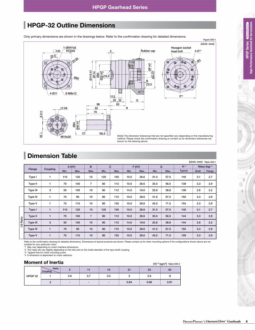
8Gearheads
HPGP Gearhead Series
Dimension Table
Backlash and Tosional Stiffness
A
A
BD
BD
0-TR×0.15
TR×0.15
-TR
TR(4)
(5)(1)
(2)
(3)
θD
TTL
A/B
See Fig. 021-1, Table 021-1, Table 021-2
See Fig. 021-1See Fig. 021-1, Table 021-1 to 2
θ=D+
BA
T-TL
(Unit: mm)
HPGP-11 Outline DimensionsOnly primary dimensions are shown in the drawings below. Refer to the confirmation drawing for detailed dimensions.
Formula 021-1
Table 022-1
28.5°
7.5
0 -0.1
E*4
□40
4 h9
4 h9
Ø10
h7
Ø29
1520
27
Ø5
H7
Ø39
.5Ø
40 h
7
ØA
H7
3
15
H
G5
2.2
BØ
24
P
1-Ø2.5H7X4PCD18
4-M4×64-Ø3.4
R0.4C0.5
C0.6
C0.5
M3×6
4-D*3
ØF
H7
ØC
Ø46
Ø18
Table 21-1
arc min ×10-4rad arc min ×10-4radD A/B
kgfm/arc min ×100Nm/rad
11
14
20
32
50
65
5213745511152133455111521334551115213345511152133454512152025
3.0
3.0
3.0
3.0
3.0
3.0
8.7
8.7
8.7
8.7
8.7
8.7
2.5
3.0
2.2
2.7
1.5
2.0
1.3
1.7
1.3
1.7
1.3
1.7
7.3
8.7
6.4
7.9
4.4
5.8
3.8
4.9
3.8
4.9
3.8
4.9
0.065
0.14
0.55
2.2
14
38
22
47
180
740
4700
13000
arc min ×10-4rad arc min ×10-4radD A/B
kgfm/arc min ×100Nm/rad
14
20
32
50
65
511152133455111521334551115213345511152133454512152025
1.0
1.0
1.0
1.0
1.0
2.9
2.9
2.9
2.9
2.9
1.1
1.7
0.6
1.1
0.5
1.0
0.5
1.0
0.5
1.0
3.2
4.9
1.7
3.2
1.5
2.9
1.5
2.9
1.5
2.9
0.14
0.55
2.2
14
38
47
180
740
4700
13000
Ø24
Ø40
Detail PCustomer's part
0.4 (Min.0.2)
Clearance0.5 or more
Recommended clearance dimension for customer's part mounted to the output flange(Note)When using a gearhead with an output flange, it is recommended for the customer to design clearance between the part mounted on the output flange and the housing face as shown in the figure on the left. The clearance is needed because the distance between the output flange and the oil seal (non-rotating) is small (min. 0.2mm).
Output flange
2-Hexagon socket head locking screw2-Screw with gasket
018 019
HPGP Gearhead Series
Figure 022-1
HPGP Gearhead Series
■ Gearhead - Standard backlash (BL3) (≤ 3 arc-min)
Torsional stiffnessRatioSizeRatioSize Backlash Torsion angle on one side
at TR X 0.15Torsional stiffness
BacklashTorsion angle on one side at TR X 0.15
■ Gearhead - Reduced backlash (BL1) (≤ 1 arc-min)
With the input of the gear locked in place, a torque applied to the output flange will torsionally deflect in proportion to the applied torque. We generate a torsional stiffness curve by slowly applying torque to the output in the following sequence:(1) Clockwise torque to TR, (2) Return to Zero, (3) Counter-Clockwise torque to -TR, (4) Return to Zero and (5) again Clockwise torque to TR. A loop of (1) > (2) > (3) > (4) > (5) will be drawn as in Fig. 021-1.The torsional stiffness in the region from “0.15 x TR” to “TR” is is calculated using the average value of this slope. The torsional stiffness in the region from “zero torque” to “0.15 x TR” is lower. This is caused by the small amount of backlash plus engagement of the mating parts and loading of the planet gears under the initial torque applied.
Torsional stiffness curveThe vertical distance between points (2) & (4) in Fig. 021-1 is called a hysteresis loss. The hysteresis loss between “Clockwise load torque TR”and “Counter Clockwise load torque - TR” is defined as the backlash of the HPGP series. Backlash of the HPGP series is less than 3 arc-min (1 arc-min is also available).
Backlash (Hysteresis loss)
The method to calculate the total torsion angle (average value) on one side when the speed reducer applies a load in a no-load state.
Calculation of total torsion angle
Torque-torsion angle diagram
Torsion angle
TR: Rated output torqueA/B: Torsional stiffnessD: Torsion on one side at TRX0.15
Hysteresis loss = Backlash
Torque
● Calculation formula
Total torsion angle
Load torque
Torsional stiffness
Torsion angle on one sideat output torque x 0.15 torque
Output torque x 0.15 torque(=TRX0.15)
(Note) The dimension tolerances that are not specified vary depending on the manufacturing method. Please check the confirmation drawing or contact us for dimension tolerances not shown on the drawing above.
High
-Per
form
ance
Gea
rhea
d fo
r Ser
vom
otor
s
High
-Per
form
ance
Gea
rhea
d fo
r Ser
vom
otor
s HP
GP S
eries
HPGP
Ser
ies
11 not available
Mass (kg) *2
Shaft
B
1 20 50 4 28 70 5 8 17.5 26 0.34 0.30
A (H7) C GF (H7)FlangeMin. Max. Max. Min. Max. Min. Max. Min. Max.
54.5
H *1
TypicalFlange
Type I
1 20 50 4 28 70 5 8 17.5 26 0.40 0.3663.5Type I
SingleStage
TwoStage
Coupling
Refer to the confirmation drawing for detailed dimensions. Dimensions of typical products are shown. Please contact us for other mounting options if the configurations shown above are not suitable for your particular motor. *1 May vary depending on motor interface dimensions. *2 The mass will vary slightly depending on the ratio and on the inside diameter of the input shaft coupling.*3 Tapped hole for motor mounting screw.*4 E dimension is dependent on motor selection.
Moment of Inertia Table 022-2
5
0.006
21
0.004
37
0.0027
45
0.00251
CouplingRatio
HPGP 11
(Unit: mm)Table 021-2
Figure 021-1
(10-4 kgm2)
HPGP-50 Outline Dimensions
Dimension TableDimension Table
HPGP-32 Outline DimensionsOnly primary dimensions are shown in the drawings below. Refer to the confirmation drawing for detailed dimensions. Only primary dimensions are shown in the drawings below. Refer to the confirmation drawing for detailed dimensions.
Figure 025-1
Table 025-1
Figure 026-1
Table 026-1
22.5°□120
Ø32
H7Ø8
4Ø1
14Ø1
15 h
7
ØA H
7ØF H
7
5
3512.5
63G13
8 h1
135
0 -0.2
12 h97082
98H
Ø40
h7Ø8
4
B
PCD451-Ø5H7x8
4-Ø11 8-M8x12
C1 R0.4
C0.5
C0.5
M10x20
ØCØ135
Ø60
45°
55°
35°35°
55°
35°
55°
35°
□170
Ø47
H7Ø1
22Ø1
63Ø1
65 h
8
ØA H
7
H84
53 1612
7
G
B
8270
103
Ø50
h7Ø1
22
14 h9
9 h1
144
.5 0 -0
.2
8-M12x204-Ø14
C0.5
ØF H
7
C0.5
R0.4C1
M10x20
1-Ø6H7x9PCD70
Ø90
ØC
Ø190
Hexagon sockethead boltRubber cap Rubber cap
Hexagon sockethead bolt
022 023
HPGP Gearhead Series HPGP Gearhead Series
High
-per
form
ance
Gea
r Hea
ds fo
r Ser
vo M
otor
s ser
iesHP
GP se
ries
High
-per
form
ance
Gea
r Hea
ds fo
r Ser
vo M
otor
s ser
iesHP
G se
ries
High
-per
form
ance
Gea
r Hea
ds fo
r Ser
vo M
otor
s ser
iesCS
G-GH
serie
sHi
gh-p
erfo
rman
ce G
ear H
eads
for S
ervo
Mot
ors s
eries
CSF-
GH se
ries
High
-per
form
ance
Gea
r Hea
ds fo
r Ser
vo M
otor
s ser
iesHP
G se
ries (
Orth
ogon
al S
haft
Type
)
High
-per
form
ance
Gea
r Hea
ds fo
r Ser
vo M
otor
s ser
iesHP
GP se
ries
High
-per
form
ance
Gea
r Hea
ds fo
r Ser
vo M
otor
s ser
iesHP
G se
ries
High
-per
form
ance
Gea
r Hea
ds fo
r Ser
vo M
otor
s ser
iesCS
G-GH
serie
sHi
gh-p
erfo
rman
ce G
ear H
eads
for S
ervo
Mot
ors s
eries
CSF-
GH se
ries
High
-per
form
ance
Gea
r Hea
ds fo
r Ser
vo M
otor
s ser
iesHP
G se
ries (
Orth
ogon
al S
haft
Type
)
(Note) The dimension tolerances that are not specified vary depending on the manufacturing method. Please check the confirmation drawing or contact us for dimension tolerances not shown on the drawing above.
(Note) The dimension tolerances that are not specified vary depending on the manufacturing method. Please check the confirmation drawing or contact us for dimension tolerances not shown on the drawing above.
Shaft
B
1 70 200 15 90 235 19.0 41.0 45.0 81.0 20.2 17.2
A (H7) C GF (H7)FlangeMin. Max. Max. Min. Max. Min. Max. Min. Max.
202
Flange
Type I
1 70 200 15 90 235 19.0 41.0 45.0 81.0 20.4 17.4243.5
2 80 115 10 100 150 19.0 41.0 31.5 55.0 19.0 16.0176
1 70 200 15 90 235 19.0 41.0 45.0 81.0 27.5 24.5202
Type II
Type III
Type IV
Coupling TypicalMass (kg) *2H *1
Shaft
B
1 110 120 10 120 155 10.0 28.6 31.0 57.5 3.1 2.7
A (H7) C GF (H7)FlangeMin. Max. Max. Min. Max. Min. Max. Min. Max.
140
Flange
Type I
Coupling
1 70 100 7 80 112 10.0 28.6 30.0 56.5 3.3 2.9139Type II
3 50 100 10 80 112 14.0 19.6 25.8 38.8 2.6 2.2139Type III
1 70 95 10 80 115 10.0 28.6 41.0 67.5 3.3 2.9150Type IV
1 70 110 10 80 155 10.0 28.6 45.0 71.5 3.3 2.9154Type V
1 110 120 10 120 155 10.0 28.6 31.0 57.5 3.1 2.7145Type I
1 70 100 7 80 112 10.0 28.6 30.0 56.5 3.3 2.9144Type II
-33
Ratio
3 50 100 10 80 112 14.0 19.6 25.8 38.8 2.6 2.2144Type III
1 70 95 10 80 115 10.0 28.6 41.0 67.5 3.3 2.9155Type IV
1 70 110 10 80 155 10.0 28.6 45.0 71.5 3.3 2.9159Type V
TypicalMass (kg) *2H *1
E*4
4-D*3
E*4
4-D*3
Refer to the confirmation drawing for detailed dimensions. Dimensions of typical products are shown. Please contact us for other mounting options if the configurations shown above are not suitable for your particular motor. *1 May vary depending on motor interface dimensions. *2 The mass will vary slightly depending on the ratio and on the inside diameter of the input shaft coupling.*3 Tapped hole for motor mounting screw.*4 E dimension for Flange Type I, II, and IV is dependent on motor selection.
Refer to the confirmation drawing for detailed dimensions. Dimensions of typical products are shown. Please contact us for other mounting options if the configurations shown above are not suitable for your particular motor. *1 May vary depending on motor interface dimensions. *2 The mass will vary slightly depending on the ratio and on the inside diameter of the input shaft coupling.*3 Tapped hole for motor mounting screw.*4 E dimension is dependent on motor selection.
Moment of Inertia Table 025-2
5
3.9
-
11
3.7
-
15
3.5
-
21
3
0.84
33
2.8
0.66
45
.8
0.61
1
2
CouplingRatio
HPGP 32
(Unit: mm)
(Unit: mm)
(Unit: mm)
(Unit: mm)
Moment of Inertia Table 026-2
5
12
-
11
9.4
-
15
9.1
8.3
21
7
5.8
33
6.1
4.9
45
5.9
4.7
1
2
CouplingRatio
HPGP 50
(10-4 kgm2)
(10-4 kgm2)
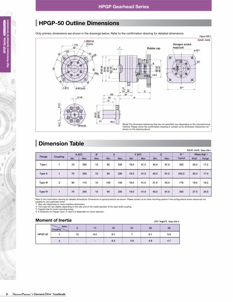
9 Gearheads
HPGP Gearhead Series
Dimension Table
Backlash and Tosional Stiffness
A
A
BD
BD
0-TR×0.15
TR×0.15
-TR
TR(4)
(5)(1)
(2)
(3)
θD
TTL
A/B
See Fig. 021-1, Table 021-1, Table 021-2
See Fig. 021-1See Fig. 021-1, Table 021-1 to 2
θ=D+
BA
T-TL
(Unit: mm)
HPGP-11 Outline DimensionsOnly primary dimensions are shown in the drawings below. Refer to the confirmation drawing for detailed dimensions.
Formula 021-1
Table 022-1
28.5°
7.5
0 -0.1
E*4
□40
4 h9
4 h9
Ø10
h7
Ø29
1520
27
Ø5
H7
Ø39
.5Ø
40 h
7
ØA
H7
3
15
H
G5
2.2
B
Ø24
P
1-Ø2.5H7X4PCD18
4-M4×64-Ø3.4
R0.4C0.5
C0.6
C0.5
M3×6
4-D*3
ØF
H7
ØC
Ø46
Ø18
Table 21-1
arc min ×10-4rad arc min ×10-4radD A/B
kgfm/arc min ×100Nm/rad
11
14
20
32
50
65
5213745511152133455111521334551115213345511152133454512152025
3.0
3.0
3.0
3.0
3.0
3.0
8.7
8.7
8.7
8.7
8.7
8.7
2.5
3.0
2.2
2.7
1.5
2.0
1.3
1.7
1.3
1.7
1.3
1.7
7.3
8.7
6.4
7.9
4.4
5.8
3.8
4.9
3.8
4.9
3.8
4.9
0.065
0.14
0.55
2.2
14
38
22
47
180
740
4700
13000
arc min ×10-4rad arc min ×10-4radD A/B
kgfm/arc min ×100Nm/rad
14
20
32
50
65
511152133455111521334551115213345511152133454512152025
1.0
1.0
1.0
1.0
1.0
2.9
2.9
2.9
2.9
2.9
1.1
1.7
0.6
1.1
0.5
1.0
0.5
1.0
0.5
1.0
3.2
4.9
1.7
3.2
1.5
2.9
1.5
2.9
1.5
2.9
0.14
0.55
2.2
14
38
47
180
740
4700
13000
Ø24
Ø40
Detail PCustomer's part
0.4 (Min.0.2)
Clearance0.5 or more
Recommended clearance dimension for customer's part mounted to the output flange(Note)When using a gearhead with an output flange, it is recommended for the customer to design clearance between the part mounted on the output flange and the housing face as shown in the figure on the left. The clearance is needed because the distance between the output flange and the oil seal (non-rotating) is small (min. 0.2mm).
Output flange
2-Hexagon socket head locking screw2-Screw with gasket
018 019
HPGP Gearhead Series
Figure 022-1
HPGP Gearhead Series
■ Gearhead - Standard backlash (BL3) (≤ 3 arc-min)
Torsional stiffnessRatioSizeRatioSize Backlash Torsion angle on one side
at TR X 0.15Torsional stiffness
BacklashTorsion angle on one side at TR X 0.15
■ Gearhead - Reduced backlash (BL1) (≤ 1 arc-min)
With the input of the gear locked in place, a torque applied to the output flange will torsionally deflect in proportion to the applied torque. We generate a torsional stiffness curve by slowly applying torque to the output in the following sequence:(1) Clockwise torque to TR, (2) Return to Zero, (3) Counter-Clockwise torque to -TR, (4) Return to Zero and (5) again Clockwise torque to TR. A loop of (1) > (2) > (3) > (4) > (5) will be drawn as in Fig. 021-1.The torsional stiffness in the region from “0.15 x TR” to “TR” is is calculated using the average value of this slope. The torsional stiffness in the region from “zero torque” to “0.15 x TR” is lower. This is caused by the small amount of backlash plus engagement of the mating parts and loading of the planet gears under the initial torque applied.
Torsional stiffness curveThe vertical distance between points (2) & (4) in Fig. 021-1 is called a hysteresis loss. The hysteresis loss between “Clockwise load torque TR”and “Counter Clockwise load torque - TR” is defined as the backlash of the HPGP series. Backlash of the HPGP series is less than 3 arc-min (1 arc-min is also available).
Backlash (Hysteresis loss)
The method to calculate the total torsion angle (average value) on one side when the speed reducer applies a load in a no-load state.
Calculation of total torsion angle
Torque-torsion angle diagram
Torsion angle
TR: Rated output torqueA/B: Torsional stiffnessD: Torsion on one side at TRX0.15
Hysteresis loss = Backlash
Torque
● Calculation formula
Total torsion angle
Load torque
Torsional stiffness
Torsion angle on one sideat output torque x 0.15 torque
Output torque x 0.15 torque(=TRX0.15)
(Note) The dimension tolerances that are not specified vary depending on the manufacturing method. Please check the confirmation drawing or contact us for dimension tolerances not shown on the drawing above.
High
-Per
form
ance
Gea
rhea
d fo
r Ser
vom
otor
s
High
-Per
form
ance
Gea
rhea
d fo
r Ser
vom
otor
s HP
GP S
eries
HPGP
Ser
ies
11 not available
Mass (kg) *2
Shaft
B
1 20 50 4 28 70 5 8 17.5 26 0.34 0.30
A (H7) C GF (H7)FlangeMin. Max. Max. Min. Max. Min. Max. Min. Max.
54.5
H *1
TypicalFlange
Type I
1 20 50 4 28 70 5 8 17.5 26 0.40 0.3663.5Type I
SingleStage
TwoStage
Coupling
Refer to the confirmation drawing for detailed dimensions. Dimensions of typical products are shown. Please contact us for other mounting options if the configurations shown above are not suitable for your particular motor. *1 May vary depending on motor interface dimensions. *2 The mass will vary slightly depending on the ratio and on the inside diameter of the input shaft coupling.*3 Tapped hole for motor mounting screw.*4 E dimension is dependent on motor selection.
Moment of Inertia Table 022-2
5
0.006
21
0.004
37
0.0027
45
0.00251
CouplingRatio
HPGP 11
(Unit: mm)Table 021-2
Figure 021-1
(10-4 kgm2)
HPGP-50 Outline Dimensions
Dimension TableDimension Table
HPGP-32 Outline DimensionsOnly primary dimensions are shown in the drawings below. Refer to the confirmation drawing for detailed dimensions. Only primary dimensions are shown in the drawings below. Refer to the confirmation drawing for detailed dimensions.
Figure 025-1
Table 025-1
Figure 026-1
Table 026-1
22.5°□120
Ø32
H7Ø8
4Ø1
14Ø1
15 h
7
ØA H
7ØF H
7
5
3512.5
63G13
8 h1
135
0 -0.2
12 h97082
98H
Ø40
h7Ø8
4
B
PCD451-Ø5H7x8
4-Ø11 8-M8x12
C1 R0.4
C0.5
C0.5
M10x20
ØCØ135
Ø60
45°
55°
35°35°
55°
35°
55°
35°
□170
Ø47
H7Ø1
22Ø1
63Ø1
65 h
8
ØA H
7
H84
53 1612
7
G
B
8270
103Ø5
0 h7
Ø122
14 h9
9 h1
144
.5 0 -0
.2
8-M12x204-Ø14
C0.5
ØF H
7
C0.5
R0.4C1
M10x20
1-Ø6H7x9PCD70
Ø90
ØC
Ø190
Hexagon sockethead boltRubber cap Rubber cap
Hexagon sockethead bolt
022 023
HPGP Gearhead Series HPGP Gearhead Series
High
-per
form
ance
Gea
r Hea
ds fo
r Ser
vo M
otor
s ser
iesHP
GP se
ries
High
-per
form
ance
Gea
r Hea
ds fo
r Ser
vo M
otor
s ser
iesHP
G se
ries
High
-per
form
ance
Gea
r Hea
ds fo
r Ser
vo M
otor
s ser
iesCS
G-GH
serie
sHi
gh-p
erfo
rman
ce G
ear H
eads
for S
ervo
Mot
ors s
eries
CSF-
GH se
ries
High
-per
form
ance
Gea
r Hea
ds fo
r Ser
vo M
otor
s ser
iesHP
G se
ries (
Orth
ogon
al S
haft
Type
)
High
-per
form
ance
Gea
r Hea
ds fo
r Ser
vo M
otor
s ser
iesHP
GP se
ries
High
-per
form
ance
Gea
r Hea
ds fo
r Ser
vo M
otor
s ser
iesHP
G se
ries
High
-per
form
ance
Gea
r Hea
ds fo
r Ser
vo M
otor
s ser
iesCS
G-GH
serie
sHi
gh-p
erfo
rman
ce G
ear H
eads
for S
ervo
Mot
ors s
eries
CSF-
GH se
ries
High
-per
form
ance
Gea
r Hea
ds fo
r Ser
vo M
otor
s ser
iesHP
G se
ries (
Orth
ogon
al S
haft
Type
)
(Note) The dimension tolerances that are not specified vary depending on the manufacturing method. Please check the confirmation drawing or contact us for dimension tolerances not shown on the drawing above.
(Note) The dimension tolerances that are not specified vary depending on the manufacturing method. Please check the confirmation drawing or contact us for dimension tolerances not shown on the drawing above.
Shaft
B
1 70 200 15 90 235 19.0 41.0 45.0 81.0 20.2 17.2
A (H7) C GF (H7)FlangeMin. Max. Max. Min. Max. Min. Max. Min. Max.
202
Flange
Type I
1 70 200 15 90 235 19.0 41.0 45.0 81.0 20.4 17.4243.5
2 80 115 10 100 150 19.0 41.0 31.5 55.0 19.0 16.0176
1 70 200 15 90 235 19.0 41.0 45.0 81.0 27.5 24.5202
Type II
Type III
Type IV
Coupling TypicalMass (kg) *2H *1
Shaft
B
1 110 120 10 120 155 10.0 28.6 31.0 57.5 3.1 2.7
A (H7) C GF (H7)FlangeMin. Max. Max. Min. Max. Min. Max. Min. Max.
140
Flange
Type I
Coupling
1 70 100 7 80 112 10.0 28.6 30.0 56.5 3.3 2.9139Type II
3 50 100 10 80 112 14.0 19.6 25.8 38.8 2.6 2.2139Type III
1 70 95 10 80 115 10.0 28.6 41.0 67.5 3.3 2.9150Type IV
1 70 110 10 80 155 10.0 28.6 45.0 71.5 3.3 2.9154Type V
1 110 120 10 120 155 10.0 28.6 31.0 57.5 3.1 2.7145Type I
1 70 100 7 80 112 10.0 28.6 30.0 56.5 3.3 2.9144Type II
-33
Ratio
3 50 100 10 80 112 14.0 19.6 25.8 38.8 2.6 2.2144Type III
1 70 95 10 80 115 10.0 28.6 41.0 67.5 3.3 2.9155Type IV
1 70 110 10 80 155 10.0 28.6 45.0 71.5 3.3 2.9159Type V
TypicalMass (kg) *2H *1
E*4
4-D*3
E*4
4-D*3
Refer to the confirmation drawing for detailed dimensions. Dimensions of typical products are shown. Please contact us for other mounting options if the configurations shown above are not suitable for your particular motor. *1 May vary depending on motor interface dimensions. *2 The mass will vary slightly depending on the ratio and on the inside diameter of the input shaft coupling.*3 Tapped hole for motor mounting screw.*4 E dimension for Flange Type I, II, and IV is dependent on motor selection.
Refer to the confirmation drawing for detailed dimensions. Dimensions of typical products are shown. Please contact us for other mounting options if the configurations shown above are not suitable for your particular motor. *1 May vary depending on motor interface dimensions. *2 The mass will vary slightly depending on the ratio and on the inside diameter of the input shaft coupling.*3 Tapped hole for motor mounting screw.*4 E dimension is dependent on motor selection.
Moment of Inertia Table 025-2
5
3.9
-
11
3.7
-
15
3.5
-
21
3
0.84
33
2.8
0.66
45
.8
0.61
1
2
CouplingRatio
HPGP 32
(Unit: mm)
(Unit: mm)
(Unit: mm)
(Unit: mm)
Moment of Inertia Table 026-2
5
12
-
11
9.4
-
15
9.1
8.3
21
7
5.8
33
6.1
4.9
45
5.9
4.7
1
2
CouplingRatio
HPGP 50
(10-4 kgm2)
(10-4 kgm2)
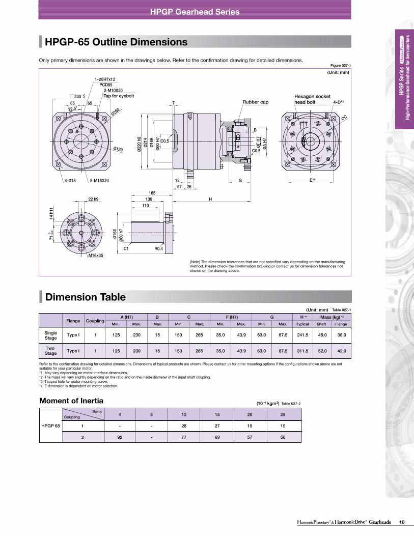
10Gearheads
HPGP Gearhead Series
Dimension Table
Backlash and Tosional Stiffness
A
A
BD
BD
0-TR×0.15
TR×0.15
-TR
TR(4)
(5)(1)
(2)
(3)
θD
TTL
A/B
See Fig. 021-1, Table 021-1, Table 021-2
See Fig. 021-1See Fig. 021-1, Table 021-1 to 2
θ=D+
BA
T-TL
(Unit: mm)
HPGP-11 Outline DimensionsOnly primary dimensions are shown in the drawings below. Refer to the confirmation drawing for detailed dimensions.
Formula 021-1
Table 022-1
28.5°
7.5
0 -0.1
E*4
□40
4 h9
4 h9
Ø10
h7
Ø29
1520
27
Ø5
H7
Ø39
.5Ø
40 h
7
ØA
H7
3
15
H
G5
2.2
BØ
24
P
1-Ø2.5H7X4PCD18
4-M4×64-Ø3.4
R0.4C0.5
C0.6
C0.5
M3×6
4-D*3
ØF
H7
ØC
Ø46
Ø18
Table 21-1
arc min ×10-4rad arc min ×10-4radD A/B
kgfm/arc min ×100Nm/rad
11
14
20
32
50
65
5213745511152133455111521334551115213345511152133454512152025
3.0
3.0
3.0
3.0
3.0
3.0
8.7
8.7
8.7
8.7
8.7
8.7
2.5
3.0
2.2
2.7
1.5
2.0
1.3
1.7
1.3
1.7
1.3
1.7
7.3
8.7
6.4
7.9
4.4
5.8
3.8
4.9
3.8
4.9
3.8
4.9
0.065
0.14
0.55
2.2
14
38
22
47
180
740
4700
13000
arc min ×10-4rad arc min ×10-4radD A/B
kgfm/arc min ×100Nm/rad
14
20
32
50
65
511152133455111521334551115213345511152133454512152025
1.0
1.0
1.0
1.0
1.0
2.9
2.9
2.9
2.9
2.9
1.1
1.7
0.6
1.1
0.5
1.0
0.5
1.0
0.5
1.0
3.2
4.9
1.7
3.2
1.5
2.9
1.5
2.9
1.5
2.9
0.14
0.55
2.2
14
38
47
180
740
4700
13000
Ø24
Ø40
Detail PCustomer's part
0.4 (Min.0.2)
Clearance0.5 or more
Recommended clearance dimension for customer's part mounted to the output flange(Note)When using a gearhead with an output flange, it is recommended for the customer to design clearance between the part mounted on the output flange and the housing face as shown in the figure on the left. The clearance is needed because the distance between the output flange and the oil seal (non-rotating) is small (min. 0.2mm).
Output flange
2-Hexagon socket head locking screw2-Screw with gasket
018 019
HPGP Gearhead Series
Figure 022-1
HPGP Gearhead Series
■ Gearhead - Standard backlash (BL3) (≤ 3 arc-min)
Torsional stiffnessRatioSizeRatioSize Backlash Torsion angle on one side
at TR X 0.15Torsional stiffness
BacklashTorsion angle on one side at TR X 0.15
■ Gearhead - Reduced backlash (BL1) (≤ 1 arc-min)
With the input of the gear locked in place, a torque applied to the output flange will torsionally deflect in proportion to the applied torque. We generate a torsional stiffness curve by slowly applying torque to the output in the following sequence:(1) Clockwise torque to TR, (2) Return to Zero, (3) Counter-Clockwise torque to -TR, (4) Return to Zero and (5) again Clockwise torque to TR. A loop of (1) > (2) > (3) > (4) > (5) will be drawn as in Fig. 021-1.The torsional stiffness in the region from “0.15 x TR” to “TR” is is calculated using the average value of this slope. The torsional stiffness in the region from “zero torque” to “0.15 x TR” is lower. This is caused by the small amount of backlash plus engagement of the mating parts and loading of the planet gears under the initial torque applied.
Torsional stiffness curveThe vertical distance between points (2) & (4) in Fig. 021-1 is called a hysteresis loss. The hysteresis loss between “Clockwise load torque TR”and “Counter Clockwise load torque - TR” is defined as the backlash of the HPGP series. Backlash of the HPGP series is less than 3 arc-min (1 arc-min is also available).
Backlash (Hysteresis loss)
The method to calculate the total torsion angle (average value) on one side when the speed reducer applies a load in a no-load state.
Calculation of total torsion angle
Torque-torsion angle diagram
Torsion angle
TR: Rated output torqueA/B: Torsional stiffnessD: Torsion on one side at TRX0.15
Hysteresis loss = Backlash
Torque
● Calculation formula
Total torsion angle
Load torque
Torsional stiffness
Torsion angle on one sideat output torque x 0.15 torque
Output torque x 0.15 torque(=TRX0.15)
(Note) The dimension tolerances that are not specified vary depending on the manufacturing method. Please check the confirmation drawing or contact us for dimension tolerances not shown on the drawing above.
High
-Per
form
ance
Gea
rhea
d fo
r Ser
vom
otor
s
High
-Per
form
ance
Gea
rhea
d fo
r Ser
vom
otor
s HP
GP S
eries
HPGP
Ser
ies
11 not available
Mass (kg) *2
Shaft
B
1 20 50 4 28 70 5 8 17.5 26 0.34 0.30
A (H7) C GF (H7)FlangeMin. Max. Max. Min. Max. Min. Max. Min. Max.
54.5
H *1
TypicalFlange
Type I
1 20 50 4 28 70 5 8 17.5 26 0.40 0.3663.5Type I
SingleStage
TwoStage
Coupling
Refer to the confirmation drawing for detailed dimensions. Dimensions of typical products are shown. Please contact us for other mounting options if the configurations shown above are not suitable for your particular motor. *1 May vary depending on motor interface dimensions. *2 The mass will vary slightly depending on the ratio and on the inside diameter of the input shaft coupling.*3 Tapped hole for motor mounting screw.*4 E dimension is dependent on motor selection.
Moment of Inertia Table 022-2
5
0.006
21
0.004
37
0.0027
45
0.00251
CouplingRatio
HPGP 11
(Unit: mm)Table 021-2
Figure 021-1
(10-4 kgm2)
HPGP-65 Outline Dimensions
Dimension Table
Only primary dimensions are shown in the drawings below. Refer to the confirmation drawing for detailed dimensions.
Table 027-1
22.5°
□230 +1-3
65 65
Ø60
H7Ø1
68Ø2
14Ø2
20 h
8
ØA H
7
7
1257 25
G
H
B
Ø80
h7Ø1
68
110130
16522 h9
14 h
1171
0 -0.2
PCD851-Ø8H7x12
4-Ø18
2-M10X20
8-M16X24
Tap for eyebolt
C0.5
C0.5
ØF H
7
C1 R0.4M16x35
ØC
Ø120
Ø260
Rubber capHexagon sockethead bolt
024
HPGP Gearhead Series
Figure 027-1
025
High
-per
form
ance
Gea
r Hea
ds fo
r Ser
vo M
otor
s ser
iesHP
GP se
ries
High
-per
form
ance
Gea
r Hea
ds fo
r Ser
vo M
otor
s ser
iesHP
G se
ries
High
-per
form
ance
Gea
r Hea
ds fo
r Ser
vo M
otor
s ser
iesCS
G-GH
serie
sHi
gh-p
erfo
rman
ce G
ear H
eads
for S
ervo
Mot
ors s
eries
CSF-
GH se
ries
High
-per
form
ance
Gea
r Hea
ds fo
r Ser
vo M
otor
s ser
iesHP
G se
ries (
Orth
ogon
al S
haft
Type
)
High
-per
form
ance
Gea
r Hea
ds fo
r Ser
vo M
otor
s ser
iesHP
GP se
ries
High
-per
form
ance
Gea
r Hea
ds fo
r Ser
vo M
otor
s ser
iesHP
G se
ries
High
-per
form
ance
Gea
r Hea
ds fo
r Ser
vo M
otor
s ser
iesCS
G-GH
serie
sHi
gh-p
erfo
rman
ce G
ear H
eads
for S
ervo
Mot
ors s
eries
CSF-
GH se
ries
High
-per
form
ance
Gea
r Hea
ds fo
r Ser
vo M
otor
s ser
iesHP
G se
ries (
Orth
ogon
al S
haft
Type
)
■NOTES
NOTES
(Note) The dimension tolerances that are not specified vary depending on the manufacturing method. Please check the confirmation drawing or contact us for dimension tolerances not shown on the drawing above.
Mass (kg) *2
Shaft
B
1 125 230 15 150 265 35.0 43.9 63.0 87.5 48.0 38.0
A (H7) C GF (H7)FlangeMin. Max. Max. Min. Max. Min. Max. Min. Max.
241.5
H *1
TypicalFlange
Type I
1 125 230 15 150 265 35.0 43.9 63.0 87.5 52.0 42.0311.5Type I
SingleStage
Two Stage
Coupling
E*4
4-D*3
(Unit: mm)
(Unit: mm)
Moment of Inertia Table 027-2
4
-
92
5
-
-
12
28
77
15
27
69
20
15
57
25
15
56
1
2
CouplingRatio
HPGP 65
Refer to the confirmation drawing for detailed dimensions. Dimensions of typical products are shown. Please contact us for other mounting options if the configurations shown above are not suitable for your particular motor. *1 May vary depending on motor interface dimensions. *2 The mass will vary slightly depending on the ratio and on the inside diameter of the input shaft coupling.*3 Tapped hole for motor mounting screw.*4 E dimension is dependent on motor selection.
(10-4 kgm2)
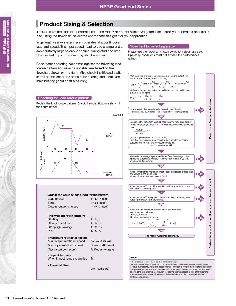
11 Gearheads
HPGP Gearhead Series
Dimension Table
Backlash and Tosional Stiffness
A
A
BD
BD
0-TR×0.15
TR×0.15
-TR
TR(4)
(5)(1)
(2)
(3)
θD
TTL
A/B
See Fig. 021-1, Table 021-1, Table 021-2
See Fig. 021-1See Fig. 021-1, Table 021-1 to 2
θ=D+
BA
T-TL
(Unit: mm)
HPGP-11 Outline DimensionsOnly primary dimensions are shown in the drawings below. Refer to the confirmation drawing for detailed dimensions.
Formula 021-1
Table 022-1
28.5°
7.5
0 -0.1
E*4
□40
4 h9
4 h9
Ø10
h7
Ø29
1520
27
Ø5
H7
Ø39
.5Ø
40 h
7
ØA
H7
3
15
H
G5
2.2
B
Ø24
P
1-Ø2.5H7X4PCD18
4-M4×64-Ø3.4
R0.4C0.5
C0.6
C0.5
M3×6
4-D*3
ØF
H7
ØC
Ø46
Ø18
Table 21-1
arc min ×10-4rad arc min ×10-4radD A/B
kgfm/arc min ×100Nm/rad
11
14
20
32
50
65
5213745511152133455111521334551115213345511152133454512152025
3.0
3.0
3.0
3.0
3.0
3.0
8.7
8.7
8.7
8.7
8.7
8.7
2.5
3.0
2.2
2.7
1.5
2.0
1.3
1.7
1.3
1.7
1.3
1.7
7.3
8.7
6.4
7.9
4.4
5.8
3.8
4.9
3.8
4.9
3.8
4.9
0.065
0.14
0.55
2.2
14
38
22
47
180
740
4700
13000
arc min ×10-4rad arc min ×10-4radD A/B
kgfm/arc min ×100Nm/rad
14
20
32
50
65
511152133455111521334551115213345511152133454512152025
1.0
1.0
1.0
1.0
1.0
2.9
2.9
2.9
2.9
2.9
1.1
1.7
0.6
1.1
0.5
1.0
0.5
1.0
0.5
1.0
3.2
4.9
1.7
3.2
1.5
2.9
1.5
2.9
1.5
2.9
0.14
0.55
2.2
14
38
47
180
740
4700
13000
Ø24
Ø40
Detail PCustomer's part
0.4 (Min.0.2)
Clearance0.5 or more
Recommended clearance dimension for customer's part mounted to the output flange(Note)When using a gearhead with an output flange, it is recommended for the customer to design clearance between the part mounted on the output flange and the housing face as shown in the figure on the left. The clearance is needed because the distance between the output flange and the oil seal (non-rotating) is small (min. 0.2mm).
Output flange
2-Hexagon socket head locking screw2-Screw with gasket
018 019
HPGP Gearhead Series
Figure 022-1
HPGP Gearhead Series
■ Gearhead - Standard backlash (BL3) (≤ 3 arc-min)
Torsional stiffnessRatioSizeRatioSize Backlash Torsion angle on one side
at TR X 0.15Torsional stiffness
BacklashTorsion angle on one side at TR X 0.15
■ Gearhead - Reduced backlash (BL1) (≤ 1 arc-min)
With the input of the gear locked in place, a torque applied to the output flange will torsionally deflect in proportion to the applied torque. We generate a torsional stiffness curve by slowly applying torque to the output in the following sequence:(1) Clockwise torque to TR, (2) Return to Zero, (3) Counter-Clockwise torque to -TR, (4) Return to Zero and (5) again Clockwise torque to TR. A loop of (1) > (2) > (3) > (4) > (5) will be drawn as in Fig. 021-1.The torsional stiffness in the region from “0.15 x TR” to “TR” is is calculated using the average value of this slope. The torsional stiffness in the region from “zero torque” to “0.15 x TR” is lower. This is caused by the small amount of backlash plus engagement of the mating parts and loading of the planet gears under the initial torque applied.
Torsional stiffness curveThe vertical distance between points (2) & (4) in Fig. 021-1 is called a hysteresis loss. The hysteresis loss between “Clockwise load torque TR”and “Counter Clockwise load torque - TR” is defined as the backlash of the HPGP series. Backlash of the HPGP series is less than 3 arc-min (1 arc-min is also available).
Backlash (Hysteresis loss)
The method to calculate the total torsion angle (average value) on one side when the speed reducer applies a load in a no-load state.
Calculation of total torsion angle
Torque-torsion angle diagram
Torsion angle
TR: Rated output torqueA/B: Torsional stiffnessD: Torsion on one side at TRX0.15
Hysteresis loss = Backlash
Torque
● Calculation formula
Total torsion angle
Load torque
Torsional stiffness
Torsion angle on one sideat output torque x 0.15 torque
Output torque x 0.15 torque(=TRX0.15)
(Note) The dimension tolerances that are not specified vary depending on the manufacturing method. Please check the confirmation drawing or contact us for dimension tolerances not shown on the drawing above.
High
-Per
form
ance
Gea
rhea
d fo
r Ser
vom
otor
s
High
-Per
form
ance
Gea
rhea
d fo
r Ser
vom
otor
s HP
GP S
eries
HPGP
Ser
ies
11 not available
Mass (kg) *2
Shaft
B
1 20 50 4 28 70 5 8 17.5 26 0.34 0.30
A (H7) C GF (H7)FlangeMin. Max. Max. Min. Max. Min. Max. Min. Max.
54.5
H *1
TypicalFlange
Type I
1 20 50 4 28 70 5 8 17.5 26 0.40 0.3663.5Type I
SingleStage
TwoStage
Coupling
Refer to the confirmation drawing for detailed dimensions. Dimensions of typical products are shown. Please contact us for other mounting options if the configurations shown above are not suitable for your particular motor. *1 May vary depending on motor interface dimensions. *2 The mass will vary slightly depending on the ratio and on the inside diameter of the input shaft coupling.*3 Tapped hole for motor mounting screw.*4 E dimension is dependent on motor selection.
Moment of Inertia Table 022-2
5
0.006
21
0.004
37
0.0027
45
0.00251
CouplingRatio
HPGP 11
(Unit: mm)Table 021-2
Figure 021-1
(10-4 kgm2)
NG
NG
NG
NG
NG
OK
OK
OK
OK
OK
OK
NG
NG
NG
NG
NG
NG
The model number is confirmed.
Example of model number Selection
Review the load torque pattern. Check the specifications shown in the figure below.
Please use the flowchart shown below for selecting a size.Operating conditions must not exceed the performanceratings.
Checking the load torque pattern
Flowchart for selecting a size
Obtain the value of each load torque pattern.Load torque T1 to Tn (Nm)Time t1 to tn (sec)Output rotational speed n1 to nn (rpm)
<Maximum rotational speed>Max. output rotational speed no max ≧ n1 to nn
Max. input rotational speed ni max n1×R to nn×R
(Restricted by motors) R: Reduction ratio
<Impact torque>When impact torque is applied Ts
<Required life> L50 = L (hours)
<Normal operation pattern>Starting T1, t1, n1
Steady operation T2, t2, n2
Stopping (slowing) T3, t3, n3
Idle T4, t4, n4
T1
T2
T3
T4
t1
n1
n2
n3
n4
t2 t3 t4
+
−
Time
Time
Load
torq
ueO
utpu
t rot
atio
nal
spee
d
CautionIf the expected operation will result in conditions where;i) Actual average load torque (Tav) > Permissible maximum value of average load torque orii) Actual average input rotational speed (ni av) > Permissible average input rotational speed (nr), then please check its effect on the speed reducer temperature rise or other factors. Consider selecting the next larger speed reducer, reduce the operating loads or take other means to ensure safe use of the gear. Exercise caution especially when the duty cycle is close to continuous operation.
Product Sizing & SelectionTo fully utilize the excellent performance of the HPGP HarmonicPlanetary® gearheads, check your operating conditions and, using the flowchart, select the appropriate size gear for your application.
Graph 028-1 T = av 60rpm ・0.3sec+ 120rpm ・3sec+ 60rpm ・0.4sec60rpm ・0.3sec・ 70Nm + 120rpm ・3sec・ 18Nm + 60rpm ・0.4sec・ 35Nm 10/3 10/3 10/310/3
60rpm ・0.3sec+ 120rpm ・3sec + 60rpm ・0.4sec+ 0rpm ・5sec
0.3sec+3sec+0.4sec+5secno = av
Calculate the average load torque applied to the output side based on the load torque pattern: Tav (Nm).
Calculate the average output speed based on the load torque pattern: no av (rpm)
Refe
r to
the
Cau
tion
note
bel
ow.
Revi
ew th
e op
erat
ion
cond
ition
s, s
ize
and
redu
ctio
n ra
tio.
Calculate the average load torque applied on the output side from the load torque pattern: Tav (Nm).
Calculate the average output speed based on the load torque pattern: no av (rpm)
Make a preliminary model selection with the following condition: Tav ≦ Average load torque (Refer to rating table).
Determine the reduction ratio (R) based on the maximum output rotational speed (no max) and maximum input rotational speed (ni max).
(A limit is placed on ni max by motors.)Calculate the maximum input speed (ni max) from the maximum output speed (no max) and the reduction ratio (R).
ni max=no max • R
ni maxno max ≧R
L10=20,000 ・ ・ (Hour)
10/3
Tr
Tavnr
ni av
Value of each load torque pattern.
Max. output rotational speed no max = 120 rpmMax. input rotational speed ni max = 5,000 rpm
(Restricted by motors)
When impact torque is applied Ts = 180 Nm
<Required life>
<Impact torque>
<Maximum rotational speed>
L50 = 30,000 (hours)
Starting T1 = 70 Nm, t1 = 0.3 sec, n1 = 60 rpmSteady operation T2 = 18 Nm, t2 = 3 sec, n2 = 120 rpmStopping (slowing) T3 = 35 Nm, t3 = 0.4 sec, n3 = 60 rpmIdle T4 = 0 Nm, t4 = 5 sec, n4 = 0 rpm
NG
NG
NG
NG
NG
NG
OK
OK
OK
OK
OK
OK
Check whether Ts is equal to or less than limit for momentary torque (Nm) in the rating table.TS = 180 Nm ≦ 217 Nm (momentary max. torque of size 20)
Make a preliminary model selection with the following conditions. T av = 30.2 Nm ≦ 72 Nm. (HPGP-20A-33 is tentatively selected based on the average load torque (see the rating table) of size 20 and reduction ratio of 33.)
5,000 rpm120 rpm
= 41.7 ≧ 33
Determine a reduction ratio (R) from the maximum output speed (no max) and maximum input speed (ni max).
Calculate the maximum input speed (ni max) from the maximum output speed (no max) and reduction ratio (R): ni max = 120 rpm・33 = 3,960 rpm
Calculate the average input speed (ni av) from the average output speed (no av) and reduction ratio (R):ni av = 46.2 rpm・33= 1,525 rpm ≦ Max average input speed of size 20 3,000 rpm
Check whether the maximum input speed is equal to or less than the values specified in the rating table. ni max = 3,960 rpm ≦ 5,000 rpm (maximum input speed of size 20)
Check whether T1 and T3 are within peak torques (Nm) on start and stop in the rating table.T1 = 70 Nm ≦ 156 Nm (Limit for repeated peak torque, size 20)T3 = 35 Nm ≦ 156 Nm (Limit for repeated peak torque, size 20)
L50 = 20,000・ 10/3
72 Nm30.2 Nm
3,000 rpm1,525 rpm
・ =712,251 (hours) ≧ 30,000 (hours)
Calculate life and check whether the calculated life meets the requirement.
The selection of model number HPGP-20A-33 is confirmed from the above calculations.
Refe
r to
the
Cau
tion
note
at t
he b
otto
m o
f pag
e 28
.Re
view
the
oper
atio
n co
nditi
ons,
siz
e an
d re
duct
ion
ratio
.
In general, a servo system rarely operates at a continuous load and speed. The input speed, load torque change and a comparatively large torque is applied during start and stop. Unexpected impact torques may also be applied.
Check your operating conditions against the following load torque pattern and select a suitable size based on the flowchart shown on the right. Also check the life and static safety coefficient of the cross roller bearing and input side main bearing (input shaft type only).
Calculate the average input speed (ni av) from the average output speed (no av) and the reduction ratio (R): ni av = no av·R ≦ Max. average input speed (nr).
Check whether the maximum input speed is equal to or less than the values in the rating table. ni max ≦ maximum input speed (rpm)
Check whether T1 and T3 are within peak torques (Nm) on start and stop in the rating table.
Check whether TS is equal to or less than the momentary max. torque (Nm) value from the ratings.
Calculate the lifetime and check whether it meets the specification requirement.Tr: Output torquenr: Max. average input speed
<Normal operation pattern>
Load torque Tn (Nm)Time tn (sec)Output rotational speed nn (rpm)
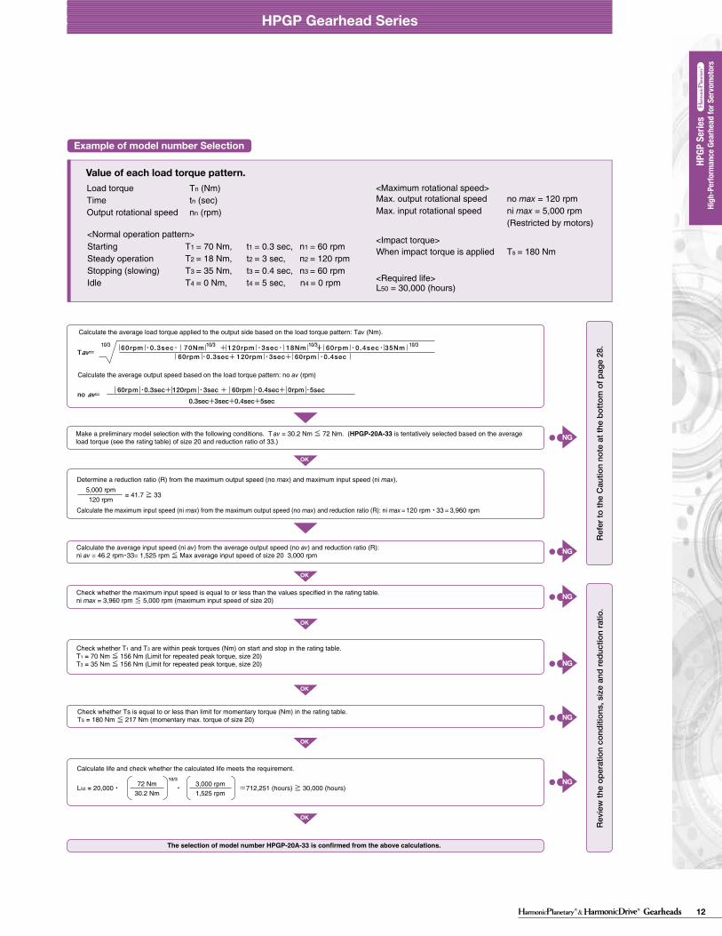
12Gearheads
HPGP Gearhead Series
Dimension Table
Backlash and Tosional Stiffness
A
A
BD
BD
0-TR×0.15
TR×0.15
-TR
TR(4)
(5)(1)
(2)
(3)
θD
TTL
A/B
See Fig. 021-1, Table 021-1, Table 021-2
See Fig. 021-1See Fig. 021-1, Table 021-1 to 2
θ=D+
BA
T-TL
(Unit: mm)
HPGP-11 Outline DimensionsOnly primary dimensions are shown in the drawings below. Refer to the confirmation drawing for detailed dimensions.
Formula 021-1
Table 022-1
28.5°
7.5
0 -0.1
E*4
□40
4 h9
4 h9
Ø10
h7
Ø29
1520
27
Ø5
H7
Ø39
.5Ø
40 h
7
ØA
H7
3
15
H
G5
2.2
BØ
24
P
1-Ø2.5H7X4PCD18
4-M4×64-Ø3.4
R0.4C0.5
C0.6
C0.5
M3×6
4-D*3
ØF
H7
ØC
Ø46
Ø18
Table 21-1
arc min ×10-4rad arc min ×10-4radD A/B
kgfm/arc min ×100Nm/rad
11
14
20
32
50
65
5213745511152133455111521334551115213345511152133454512152025
3.0
3.0
3.0
3.0
3.0
3.0
8.7
8.7
8.7
8.7
8.7
8.7
2.5
3.0
2.2
2.7
1.5
2.0
1.3
1.7
1.3
1.7
1.3
1.7
7.3
8.7
6.4
7.9
4.4
5.8
3.8
4.9
3.8
4.9
3.8
4.9
0.065
0.14
0.55
2.2
14
38
22
47
180
740
4700
13000
arc min ×10-4rad arc min ×10-4radD A/B
kgfm/arc min ×100Nm/rad
14
20
32
50
65
511152133455111521334551115213345511152133454512152025
1.0
1.0
1.0
1.0
1.0
2.9
2.9
2.9
2.9
2.9
1.1
1.7
0.6
1.1
0.5
1.0
0.5
1.0
0.5
1.0
3.2
4.9
1.7
3.2
1.5
2.9
1.5
2.9
1.5
2.9
0.14
0.55
2.2
14
38
47
180
740
4700
13000
Ø24
Ø40
Detail PCustomer's part
0.4 (Min.0.2)
Clearance0.5 or more
Recommended clearance dimension for customer's part mounted to the output flange(Note)When using a gearhead with an output flange, it is recommended for the customer to design clearance between the part mounted on the output flange and the housing face as shown in the figure on the left. The clearance is needed because the distance between the output flange and the oil seal (non-rotating) is small (min. 0.2mm).
Output flange
2-Hexagon socket head locking screw2-Screw with gasket
018 019
HPGP Gearhead Series
Figure 022-1
HPGP Gearhead Series
■ Gearhead - Standard backlash (BL3) (≤ 3 arc-min)
Torsional stiffnessRatioSizeRatioSize Backlash Torsion angle on one side
at TR X 0.15Torsional stiffness
BacklashTorsion angle on one side at TR X 0.15
■ Gearhead - Reduced backlash (BL1) (≤ 1 arc-min)
With the input of the gear locked in place, a torque applied to the output flange will torsionally deflect in proportion to the applied torque. We generate a torsional stiffness curve by slowly applying torque to the output in the following sequence:(1) Clockwise torque to TR, (2) Return to Zero, (3) Counter-Clockwise torque to -TR, (4) Return to Zero and (5) again Clockwise torque to TR. A loop of (1) > (2) > (3) > (4) > (5) will be drawn as in Fig. 021-1.The torsional stiffness in the region from “0.15 x TR” to “TR” is is calculated using the average value of this slope. The torsional stiffness in the region from “zero torque” to “0.15 x TR” is lower. This is caused by the small amount of backlash plus engagement of the mating parts and loading of the planet gears under the initial torque applied.
Torsional stiffness curveThe vertical distance between points (2) & (4) in Fig. 021-1 is called a hysteresis loss. The hysteresis loss between “Clockwise load torque TR”and “Counter Clockwise load torque - TR” is defined as the backlash of the HPGP series. Backlash of the HPGP series is less than 3 arc-min (1 arc-min is also available).
Backlash (Hysteresis loss)
The method to calculate the total torsion angle (average value) on one side when the speed reducer applies a load in a no-load state.
Calculation of total torsion angle
Torque-torsion angle diagram
Torsion angle
TR: Rated output torqueA/B: Torsional stiffnessD: Torsion on one side at TRX0.15
Hysteresis loss = Backlash
Torque
● Calculation formula
Total torsion angle
Load torque
Torsional stiffness
Torsion angle on one sideat output torque x 0.15 torque
Output torque x 0.15 torque(=TRX0.15)
(Note) The dimension tolerances that are not specified vary depending on the manufacturing method. Please check the confirmation drawing or contact us for dimension tolerances not shown on the drawing above.
High
-Per
form
ance
Gea
rhea
d fo
r Ser
vom
otor
s
High
-Per
form
ance
Gea
rhea
d fo
r Ser
vom
otor
s HP
GP S
eries
HPGP
Ser
ies
11 not available
Mass (kg) *2
Shaft
B
1 20 50 4 28 70 5 8 17.5 26 0.34 0.30
A (H7) C GF (H7)FlangeMin. Max. Max. Min. Max. Min. Max. Min. Max.
54.5
H *1
TypicalFlange
Type I
1 20 50 4 28 70 5 8 17.5 26 0.40 0.3663.5Type I
SingleStage
TwoStage
Coupling
Refer to the confirmation drawing for detailed dimensions. Dimensions of typical products are shown. Please contact us for other mounting options if the configurations shown above are not suitable for your particular motor. *1 May vary depending on motor interface dimensions. *2 The mass will vary slightly depending on the ratio and on the inside diameter of the input shaft coupling.*3 Tapped hole for motor mounting screw.*4 E dimension is dependent on motor selection.
Moment of Inertia Table 022-2
5
0.006
21
0.004
37
0.0027
45
0.00251
CouplingRatio
HPGP 11
(Unit: mm)Table 021-2
Figure 021-1
(10-4 kgm2)
NG
NG
NG
NG
NG
OK
OK
OK
OK
OK
OK
NG
NG
NG
NG
NG
NG
The model number is confirmed.
Example of model number Selection
Review the load torque pattern. Check the specifications shown in the figure below.
Please use the flowchart shown below for selecting a size.Operating conditions must not exceed the performanceratings.
Checking the load torque pattern
Flowchart for selecting a size
Obtain the value of each load torque pattern.Load torque T1 to Tn (Nm)Time t1 to tn (sec)Output rotational speed n1 to nn (rpm)
<Maximum rotational speed>Max. output rotational speed no max ≧ n1 to nn
Max. input rotational speed ni max n1×R to nn×R
(Restricted by motors) R: Reduction ratio
<Impact torque>When impact torque is applied Ts
<Required life> L50 = L (hours)
<Normal operation pattern>Starting T1, t1, n1
Steady operation T2, t2, n2
Stopping (slowing) T3, t3, n3
Idle T4, t4, n4
T1
T2
T3
T4
t1
n1
n2
n3
n4
t2 t3 t4
+
−
Time
Time
Load
torq
ueO
utpu
t rot
atio
nal
spee
d
CautionIf the expected operation will result in conditions where;i) Actual average load torque (Tav) > Permissible maximum value of average load torque orii) Actual average input rotational speed (ni av) > Permissible average input rotational speed (nr), then please check its effect on the speed reducer temperature rise or other factors. Consider selecting the next larger speed reducer, reduce the operating loads or take other means to ensure safe use of the gear. Exercise caution especially when the duty cycle is close to continuous operation.
Product Sizing & SelectionTo fully utilize the excellent performance of the HPGP HarmonicPlanetary® gearheads, check your operating conditions and, using the flowchart, select the appropriate size gear for your application.
Graph 028-1 T = av 60rpm ・0.3sec+ 120rpm ・3sec+ 60rpm ・0.4sec60rpm ・0.3sec・ 70Nm + 120rpm ・3sec・ 18Nm + 60rpm ・0.4sec・ 35Nm 10/3 10/3 10/310/3
60rpm ・0.3sec+ 120rpm ・3sec + 60rpm ・0.4sec+ 0rpm ・5sec
0.3sec+3sec+0.4sec+5secno = av
Calculate the average load torque applied to the output side based on the load torque pattern: Tav (Nm).
Calculate the average output speed based on the load torque pattern: no av (rpm)
Refe
r to
the
Cau
tion
note
bel
ow.
Revi
ew th
e op
erat
ion
cond
ition
s, s
ize
and
redu
ctio
n ra
tio.
Calculate the average load torque applied on the output side from the load torque pattern: Tav (Nm).
Calculate the average output speed based on the load torque pattern: no av (rpm)
Make a preliminary model selection with the following condition: Tav ≦ Average load torque (Refer to rating table).
Determine the reduction ratio (R) based on the maximum output rotational speed (no max) and maximum input rotational speed (ni max).
(A limit is placed on ni max by motors.)Calculate the maximum input speed (ni max) from the maximum output speed (no max) and the reduction ratio (R).
ni max=no max • R
ni maxno max ≧R
L10=20,000 ・ ・ (Hour)
10/3
Tr
Tavnr
ni av
Value of each load torque pattern.
Max. output rotational speed no max = 120 rpmMax. input rotational speed ni max = 5,000 rpm
(Restricted by motors)
When impact torque is applied Ts = 180 Nm
<Required life>
<Impact torque>
<Maximum rotational speed>
L50 = 30,000 (hours)
Starting T1 = 70 Nm, t1 = 0.3 sec, n1 = 60 rpmSteady operation T2 = 18 Nm, t2 = 3 sec, n2 = 120 rpmStopping (slowing) T3 = 35 Nm, t3 = 0.4 sec, n3 = 60 rpmIdle T4 = 0 Nm, t4 = 5 sec, n4 = 0 rpm
NG
NG
NG
NG
NG
NG
OK
OK
OK
OK
OK
OK
Check whether Ts is equal to or less than limit for momentary torque (Nm) in the rating table.TS = 180 Nm ≦ 217 Nm (momentary max. torque of size 20)
Make a preliminary model selection with the following conditions. T av = 30.2 Nm ≦ 72 Nm. (HPGP-20A-33 is tentatively selected based on the average load torque (see the rating table) of size 20 and reduction ratio of 33.)
5,000 rpm120 rpm
= 41.7 ≧ 33
Determine a reduction ratio (R) from the maximum output speed (no max) and maximum input speed (ni max).
Calculate the maximum input speed (ni max) from the maximum output speed (no max) and reduction ratio (R): ni max = 120 rpm・33 = 3,960 rpm
Calculate the average input speed (ni av) from the average output speed (no av) and reduction ratio (R):ni av = 46.2 rpm・33= 1,525 rpm ≦ Max average input speed of size 20 3,000 rpm
Check whether the maximum input speed is equal to or less than the values specified in the rating table. ni max = 3,960 rpm ≦ 5,000 rpm (maximum input speed of size 20)
Check whether T1 and T3 are within peak torques (Nm) on start and stop in the rating table.T1 = 70 Nm ≦ 156 Nm (Limit for repeated peak torque, size 20)T3 = 35 Nm ≦ 156 Nm (Limit for repeated peak torque, size 20)
L50 = 20,000・ 10/3
72 Nm30.2 Nm
3,000 rpm1,525 rpm
・ =712,251 (hours) ≧ 30,000 (hours)
Calculate life and check whether the calculated life meets the requirement.
The selection of model number HPGP-20A-33 is confirmed from the above calculations.
Refe
r to
the
Cau
tion
note
at t
he b
otto
m o
f pag
e 28
.Re
view
the
oper
atio
n co
nditi
ons,
siz
e an
d re
duct
ion
ratio
.
In general, a servo system rarely operates at a continuous load and speed. The input speed, load torque change and a comparatively large torque is applied during start and stop. Unexpected impact torques may also be applied.
Check your operating conditions against the following load torque pattern and select a suitable size based on the flowchart shown on the right. Also check the life and static safety coefficient of the cross roller bearing and input side main bearing (input shaft type only).
Calculate the average input speed (ni av) from the average output speed (no av) and the reduction ratio (R): ni av = no av·R ≦ Max. average input speed (nr).
Check whether the maximum input speed is equal to or less than the values in the rating table. ni max ≦ maximum input speed (rpm)
Check whether T1 and T3 are within peak torques (Nm) on start and stop in the rating table.
Check whether TS is equal to or less than the momentary max. torque (Nm) value from the ratings.
Calculate the lifetime and check whether it meets the specification requirement.Tr: Output torquenr: Max. average input speed
<Normal operation pattern>
Load torque Tn (Nm)Time tn (sec)Output rotational speed nn (rpm)
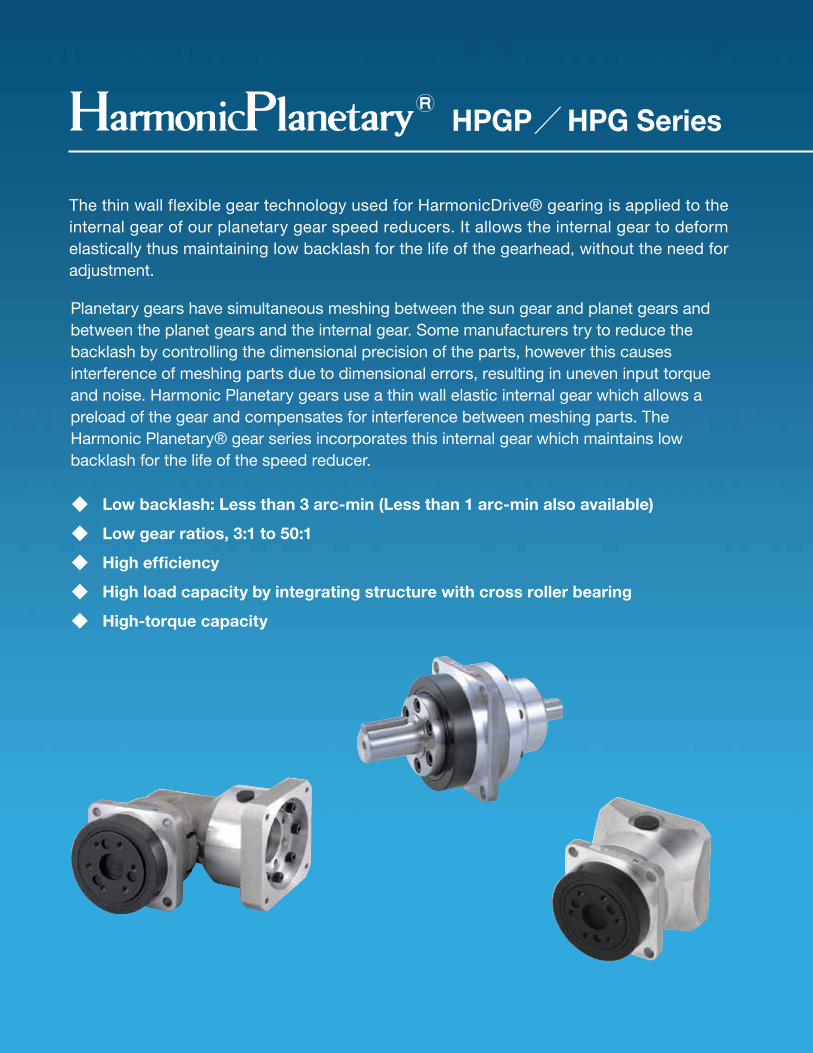
13Gearheads2 3
HPGP/HPG Series
The thin wall flexible gear technology used for HarmonicDrive® gearing is applied to the internal gear of our planetary gear speed reducers. It allows the internal gear to deform elastically thus maintaining low backlash for the life of the gearhead, without the need for adjustment.
Planetary gears have simultaneous meshing between the sun gear and planet gears and between the planet gears and the internal gear. Some manufacturers try to reduce the backlash by controlling the dimensional precision of the parts, however this causes interference of meshing parts due to dimensional errors, resulting in uneven input torque and noise. Harmonic Planetary gears use a thin wall elastic internal gear which allows a preload of the gear and compensates for interference between meshing parts. The Harmonic Planetary® gear series incorporates this internal gear which maintains low backlash for the life of the speed reducer.
◆ Low backlash: Less than 3 arc-min (Less than 1 arc-min also available)
◆ Low gear ratios, 3:1 to 50:1
◆ High efficiency
◆ High load capacity by integrating structure with cross roller bearing
◆ High-torque capacity
Shielded or sealed input bearing
Backlash compensating internal gear
Motor mounting flange
Quick Connect™ coupling for easy mounting of any servomotor
Robust cross roller bearing and output flange are integrated to provide high moment stiffness, high load capacity and precise positioning accuracy.
The cross roller bearing output flange serves as the second stage carrier for a rugged, compact design.
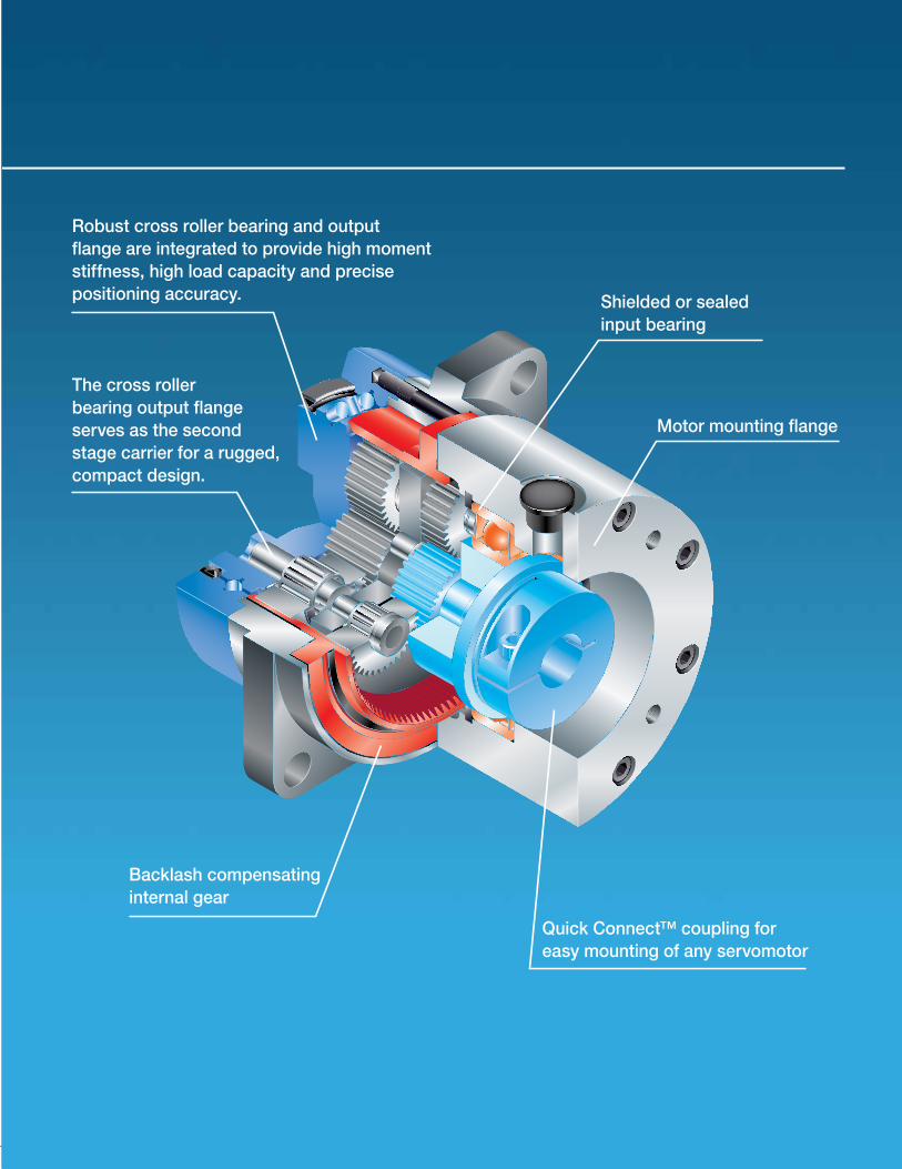
14 Gearheads2 3
HPGP/HPG Series
The thin wall flexible gear technology used for HarmonicDrive® gearing is applied to the internal gear of our planetary gear speed reducers. It allows the internal gear to deform elastically thus maintaining low backlash for the life of the gearhead, without the need for adjustment.
Planetary gears have simultaneous meshing between the sun gear and planet gears and between the planet gears and the internal gear. Some manufacturers try to reduce the backlash by controlling the dimensional precision of the parts, however this causes interference of meshing parts due to dimensional errors, resulting in uneven input torque and noise. Harmonic Planetary gears use a thin wall elastic internal gear which allows a preload of the gear and compensates for interference between meshing parts. The Harmonic Planetary® gear series incorporates this internal gear which maintains low backlash for the life of the speed reducer.
◆ Low backlash: Less than 3 arc-min (Less than 1 arc-min also available)
◆ Low gear ratios, 3:1 to 50:1
◆ High efficiency
◆ High load capacity by integrating structure with cross roller bearing
◆ High-torque capacity
Shielded or sealed input bearing
Backlash compensating internal gear
Motor mounting flange
Quick Connect™ coupling for easy mounting of any servomotor
Robust cross roller bearing and output flange are integrated to provide high moment stiffness, high load capacity and precise positioning accuracy.
The cross roller bearing output flange serves as the second stage carrier for a rugged, compact design.
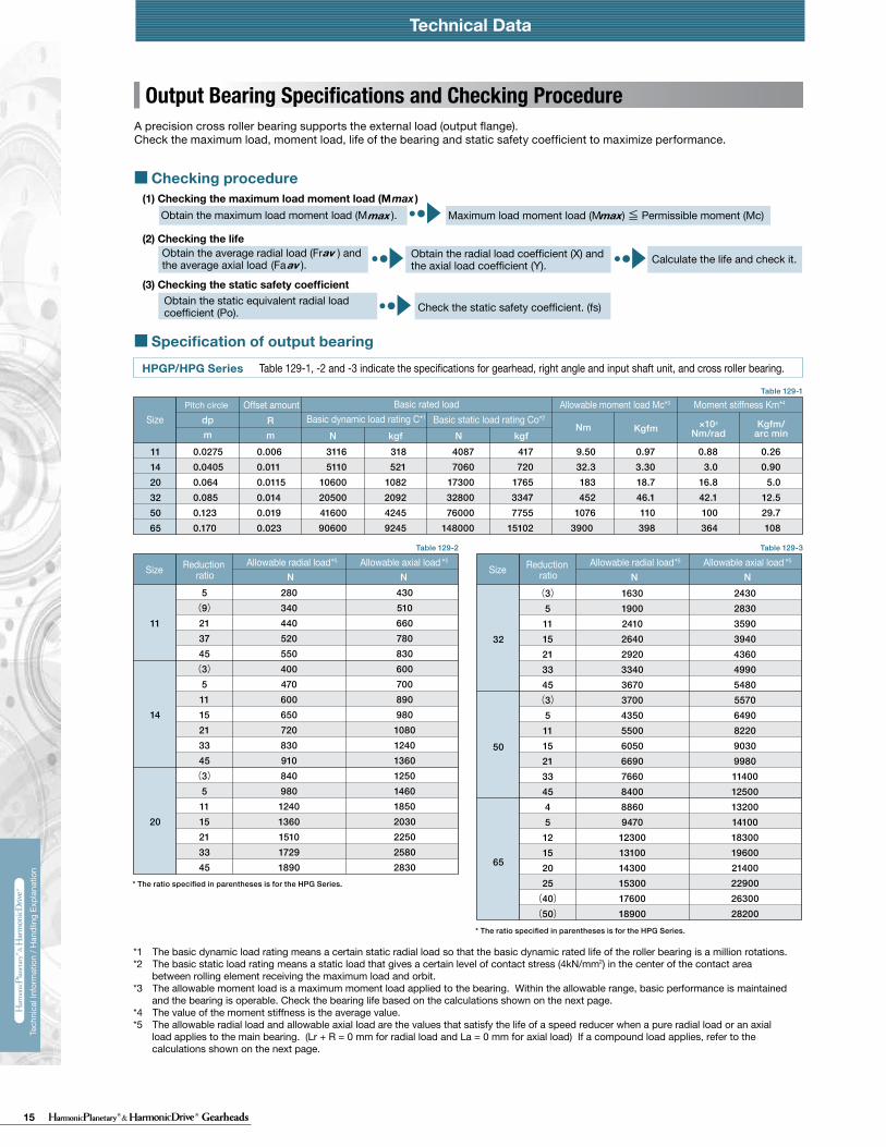
15 Gearheads
Technical DataTechnical Data Technical Data
230 231
Tech
nica
l Inf
orm
atio
n / H
andl
ing
Expl
anat
ion
Tech
nica
l Inf
orm
atio
n / H
andl
ing
Expl
anat
ion
HPG HPF
Calculate:Maximum load moment load (Mi max)Maximum load axial load (Fai max)Maximum load radial load (Fri max)
Calculate:Average moment load (Mi av)Average axial load (Fai av) Average input speed (Ni av)
Maximum load moment load (Mi max) ≦ Permissible moment load (Mc)Maximum load axial load (Fai max) ≦ Permissible axial load (Fac)Maximum load radial load (Fri max) ≦ Permissible radial load (Frc)
Calculate the life and check it.
(2) Checking the life
(1) Checking maximum load
Time: t
Time: t
n1
n2
n3
M1
M2
M3
M4
n4
t1 t2 t3 t4
L10
NiCrPci
LifeAverage input rotational speedBasic dynamic rated loadDynamic equivalent radial load
HourrpmN (kgf)N
av
111420325065
0.137 × Mi av + 1.232 × Fai av0.444 × Mi av + 1.426 × Fai av
0.041 × Mi av + 1.232 × Fai av
0.109 × Mi av + 1.232 × Fai av0.071 × Mi av + 1.232 × Fai av0.053 × Mi av + 1.232 × Fai av
maxmax
Fai
Lri
Fri
Lai
111420325065
111420325065
2532
2532
*1 The allowable axial load is the tolerance of an axial load applied to the shaft center.*2 The allowable radial load of HPG series is the tolerance of a radial load applied to the shaft length center.*3 The allowable radial load of HPG series is the tolerance of a radial load applied to the point of 20 mm from the shaft edge (input flange edge).
2532 106 × Mi av + 2.7 × Fai av
121 × Mi av + 2.7 × Fai av
Fai
Fri
Lai
Lri
Check the maximum load and life of the bearing on the input side if the reducer is an HPG input shaft unit or an HPF hollow shaft unit.
FriFaiLri,Lai
The specification of the input side main bearing of the input shaft unit is shown below.
If moment load and axial load fluctuate, they should be converted into the average load to check the life of the bearing.
Calculate the bearing life according to Calculation Formula 132-5 and check the life.
Specification of input shaft bearing
Specification of input shaft bearing
Table 133-1
Table 134-1
Table 134-2
Figure 134-1
Formula 134-2
Formula 134-3
Formula 134-4
Graph 134-1
Formula 134-5
Table 133-2
Size
Table 133-3
Table 133-4
〔Note: Table 133-2 and 133-4〕
External load influence diagram
Dynamic equivalent radial load
Size
Dynamic equivalent radial load
HPG HPF
HPG
HPF
HPG HPF
HPG
HPF
Pci
N270058009700
225003550051000
kgf275590990
230036005200
N127031505600148002510039500
kgf129320570151025604050
Nm0.166.313.544.496.9210
kgfm0.0160.641.384.539.8821.4
N2456571206328555408600
kgf2567123335565878
N20.6500902197032265267
kgf2.15192
201329537
N1450029700
kgf14803030
N1010020100
kgf10302050
Nm1019
kgfm1.021.93
N15383263
kgf157333
N522966
kgf53.298.5
Pci
HPG HPF
Formula 134-1
Checking procedure
Specification of input shaft bearing
SizeBasic rated load
Basic dynamic rated load Cr Basic static rated load Cor
SizeAllowable moment load Mc Allowable axial load Fac *1 Allowable radial load Frc *2
SizeBasic rated load
Basic dynamic rated load Cr Basic static rated load Cor
SizeAllowable moment load Mc Allowable axial load Fac *1 Allowable radial load Frc *3
Calculating maximum load moment load to input shaft
How to calculate average load(Average moment load, average axial load, average input rotational frequency)
Mi max ≦ Mc (Permissible moment load)Fai max ≦ Fac (Permissible axial load)
Max. radial loadMax. axial load————
N (kgf)N (kgf)m
See Fig. 134-1.See Fig. 134-1.See Fig. 134-1.
The maximum load moment load (Mi max ) is calculated as follows.Check that the following formulas are established in all circumstances:
Inpu
t spe
edM
omen
t loa
d
How to calculate the average moment load (Miav )
How to calculate the average axial load (Faiav)
How to calculate the average output rotational frequency (Niav)
Calculating life of input side bearing
Miav Average moment load Nm (kgfm) See Formula 134-2Faiav Average axial load N (kgf) See Formula 134-3
See Formula 134-4See Table 133-1 and -3See Table 134-1 and -2
Input Bearing Specifications and Checking Procedure
226 227
Tech
nica
l Inf
orm
atio
n / H
andl
ing
Expl
anat
ion
Tech
nica
l Inf
orm
atio
n / H
andl
ing
Expl
anat
ion
* The ratio specified in parentheses is for the HPG Series.
* The ratio specified in parentheses is for the HPG Series.
4305106607808306007008909801080124013601250146018502030225025802830
28034044052055040047060065072083091084098012401360151017291890
5(9)
213745(3)
51115213345(3)
51115213345
11
14
20
24302830359039404360499054805570649082209030998011400125001320014100183001960021400229002630028200
1630190024102640292033403670370043505500605066907660840088609470
123001310014300153001760018900
(3)51115213345(3)
511152133454512152025
(40)(50)
32
50
65
0.260.90
5.012.529.7108
0.883.0
16.842.1100364
0.973.3018.746.1110398
9.5032.3183452
10763900
417720
176533477755
15102
40877060
173003280076000
148000
318521
1082209242459245
31165110
10600205004160090600
0.0060.0110.01150.0140.0190.023
0.02750.04050.0640.0850.1230.170
111420325065
109322674385889917454
73215192938596211693
0.895.0123096
3.01742100323
2.7614.826.381.3220
271452587972156
72017653347775515204
7060173003280076000149000
5211082209242458327
511010600205004160081600
0.0110.01150.0140.019
0.0225
0.04050.0640.0850.1230.170
1420324565
19903940
13302640
11.325.7
37.986.1
41.895
410932
20714071
2030039900
11632296
1140022500
0.01530.015
0.0850.1115
2532
A precision cross roller bearing supports the external load (output flange).Check the maximum load, moment load, life of the bearing and static safety coefficient to maximize performance.
Output Bearing Specifications and Checking Procedure
Table 129-1, -2 and -3 indicate the specifications for gearhead, right angle and input shaft unit, and cross roller bearing.
Table 130-1 indicates the specifications for cross roller bearing.
Table 130-2 indicates the specifications for cross roller bearing.
Checking procedure
Specification of output bearing
Table 129-1
Table 129-3Table 129-2
HPGP/HPG Series
Table 130-1
CSG-GH/CSF-GH Series
〔Note:Table 129-1, -2 and -3 Table 130-1 and -2〕
Table 130-2
HPF Series
Technical Data Technical Data
SizePitch circle Basic rated load Allowable moment load Mc*3 Moment stiffness Km*4
Basic dynamic load rating C*1 Basic static load rating Co*2
Offset amount
Size
Basic load rating Allowable moment load Mc*3
Allowable radial load*5
Allowable axial load*5
Moment stiffness Km*4
Basic dynamic load rating C*1
Basic static load rating Co*2
Offset amount
Size
Pitch circle
Pitch circle
Basic load rating Allowable moment load Mc*3
Allowable radial load*5
Allowable axial load*5
Moment stiffness Km*4
Basic dynamic load rating C*1
Basic static load rating Co*2
Offset amount
N N N N
dpm
Rm
Nm Kgfm ×104
Nm/radKgfm/
arc minN kgf N kgf
m
dp
m
R
Nm kgfmkgf N N×104
Nm/radNkgfNkgfm/
arc min
m
dp
m
R
Nm kgfmkgf N N×104
Nm/radNkgfNkgfm/
arc min
(1) Checking the maximum load moment load (M )max
(2) Checking the life
(3) Checking the static safety coefficient
Obtain the maximum load moment load (M ).
Obtain the static equivalent radial load coefficient (Po). Check the static safety coefficient. (fs)
Calculate the life and check it.Obtain the radial load coefficient (X) and the axial load coefficient (Y).
Maximum load moment load (M ) ≦ Permissible moment (Mc)max max
Obtain the average radial load (Fr ) and the average axial load (Fa ).av
av
Reduction ratio
Allowable axial load *5 Allowable radial load *5
Size Reduction ratio
Allowable axial load *5 Allowable radial load *5
Size
*1 The basic dynamic load rating means a certain static radial load so that the basic dynamic rated life of the roller bearing is a million rotations.*2 The basic static load rating means a static load that gives a certain level of contact stress (4kN/mm2) in the center of the contact area
between rolling element receiving the maximum load and orbit.*3 The allowable moment load is a maximum moment load applied to the bearing. Within the allowable range, basic performance is maintained
and the bearing is operable. Check the bearing life based on the calculations shown on the next page.*4 The value of the moment stiffness is the average value. *5 The allowable radial load and allowable axial load are the values that satisfy the life of a speed reducer when a pure radial load or an axial
load applies to the main bearing. (Lr + R = 0 mm for radial load and La = 0 mm for axial load) If a compound load applies, refer to the calculations shown on the next page.
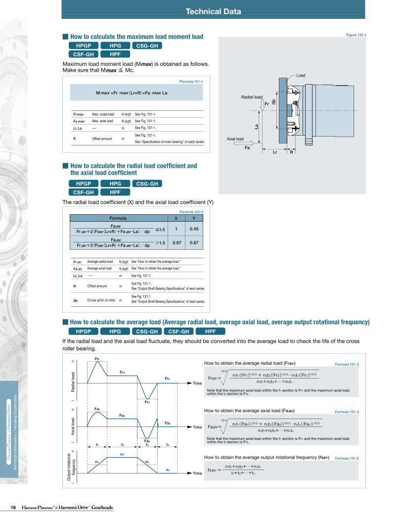
16 Gearheads
Technical DataTechnical Data Technical Data
230 231
Tech
nica
l Inf
orm
atio
n / H
andl
ing
Expl
anat
ion
Tech
nica
l Inf
orm
atio
n / H
andl
ing
Expl
anat
ion
HPG HPF
Calculate:Maximum load moment load (Mi max)Maximum load axial load (Fai max)Maximum load radial load (Fri max)
Calculate:Average moment load (Mi av)Average axial load (Fai av) Average input speed (Ni av)
Maximum load moment load (Mi max) ≦ Permissible moment load (Mc)Maximum load axial load (Fai max) ≦ Permissible axial load (Fac)Maximum load radial load (Fri max) ≦ Permissible radial load (Frc)
Calculate the life and check it.
(2) Checking the life
(1) Checking maximum load
Time: t
Time: t
n1
n2
n3
M1
M2
M3
M4
n4
t1 t2 t3 t4
L10
NiCrPci
LifeAverage input rotational speedBasic dynamic rated loadDynamic equivalent radial load
HourrpmN (kgf)N
av
111420325065
0.137 × Mi av + 1.232 × Fai av0.444 × Mi av + 1.426 × Fai av
0.041 × Mi av + 1.232 × Fai av
0.109 × Mi av + 1.232 × Fai av0.071 × Mi av + 1.232 × Fai av0.053 × Mi av + 1.232 × Fai av
maxmax
Fai
Lri
Fri
Lai
111420325065
111420325065
2532
2532
*1 The allowable axial load is the tolerance of an axial load applied to the shaft center.*2 The allowable radial load of HPG series is the tolerance of a radial load applied to the shaft length center.*3 The allowable radial load of HPG series is the tolerance of a radial load applied to the point of 20 mm from the shaft edge (input flange edge).
2532 106 × Mi av + 2.7 × Fai av
121 × Mi av + 2.7 × Fai av
Fai
Fri
Lai
Lri
Check the maximum load and life of the bearing on the input side if the reducer is an HPG input shaft unit or an HPF hollow shaft unit.
FriFaiLri,Lai
The specification of the input side main bearing of the input shaft unit is shown below.
If moment load and axial load fluctuate, they should be converted into the average load to check the life of the bearing.
Calculate the bearing life according to Calculation Formula 132-5 and check the life.
Specification of input shaft bearing
Specification of input shaft bearing
Table 133-1
Table 134-1
Table 134-2
Figure 134-1
Formula 134-2
Formula 134-3
Formula 134-4
Graph 134-1
Formula 134-5
Table 133-2
Size
Table 133-3
Table 133-4
〔Note: Table 133-2 and 133-4〕
External load influence diagram
Dynamic equivalent radial load
Size
Dynamic equivalent radial load
HPG HPF
HPG
HPF
HPG HPF
HPG
HPF
Pci
N270058009700
225003550051000
kgf275590990
230036005200
N127031505600148002510039500
kgf129320570151025604050
Nm0.166.313.544.496.9210
kgfm0.0160.641.384.539.8821.4
N2456571206328555408600
kgf2567123335565878
N20.6500902197032265267
kgf2.15192
201329537
N1450029700
kgf14803030
N1010020100
kgf10302050
Nm1019
kgfm1.021.93
N15383263
kgf157333
N522966
kgf53.298.5
Pci
HPG HPF
Formula 134-1
Checking procedure
Specification of input shaft bearing
SizeBasic rated load
Basic dynamic rated load Cr Basic static rated load Cor
SizeAllowable moment load Mc Allowable axial load Fac *1 Allowable radial load Frc *2
SizeBasic rated load
Basic dynamic rated load Cr Basic static rated load Cor
SizeAllowable moment load Mc Allowable axial load Fac *1 Allowable radial load Frc *3
Calculating maximum load moment load to input shaft
How to calculate average load(Average moment load, average axial load, average input rotational frequency)
Mi max ≦ Mc (Permissible moment load)Fai max ≦ Fac (Permissible axial load)
Max. radial loadMax. axial load————
N (kgf)N (kgf)m
See Fig. 134-1.See Fig. 134-1.See Fig. 134-1.
The maximum load moment load (Mi max ) is calculated as follows.Check that the following formulas are established in all circumstances:
Inpu
t spe
edM
omen
t loa
d
How to calculate the average moment load (Miav )
How to calculate the average axial load (Faiav)
How to calculate the average output rotational frequency (Niav)
Calculating life of input side bearing
Miav Average moment load Nm (kgfm) See Formula 134-2Faiav Average axial load N (kgf) See Formula 134-3
See Formula 134-4See Table 133-1 and -3See Table 134-1 and -2
Input Bearing Specifications and Checking Procedure
228 229
Tech
nica
l Inf
orm
atio
n / H
andl
ing
Expl
anat
ion
Tech
nica
l Inf
orm
atio
n / H
andl
ing
Expl
anat
ion
Technical Data Technical Data
HPG HPFCSG-GH CSF-GHHPGPHow to calculate the maximum load moment load
How to calculate the radial load coefficient and the axial load coefficient
The radial load coefficient (X) and the axial load coefficient (Y)
HPGHPF
CSG-GHCSF-GH
HPG HPFCSG-GH CSF-GH
HPG HPFCSG-GH CSF-GHHPGP
HPG HPFCSG-GH CSF-GHHPGP
HPGP
HPGHPF
CSG-GHCSF-GH
HPGP
HPGP
Formula 131-1
Formula 131-3
Formula 131-4
Formula 131-5
Formula 131-2
Figure 131-1
Load coefficient
Static safety coefficient
Formula 132-1
Table 132-1
Table 132-2
Formula 132-3
Figure 132-1
Formula 132-4 Formula 132-5
Formula 132-2
Note
Note that the maximum axial load within the t1 section is Fr1 and the maximum axial load within the t3 section is Fr3.
Note that the maximum axial load within the t1 section is Fr1 and the maximum axial load within the t3 section is Fr3.
Fr1
Fr2
Fr4
Fa1
Fa2
Fa4
Fa3t1 t2 t3 t4
n1
n2
n4
n3
Fr3
Time
Time
Time
N (kgf)
N (kgf)
m
m
M =Fr (Lr+R)+Fa ・ Lamax max max
N (kgf)
N (kgf)
m
m
m
Fr
Fa
Lr, La
R
dp
av
av
1
0.67 0.67
0.45≦1.5Fa
Fr +2(Fr (Lr+R)+Fa ・La)/dpavav avav
>1.5FaFr +2(Fr (Lr+R)+Fa ・La)/dpavav av
av
hourrpmN (kgf)N (kgf)
N (kgf)N (kgf)m––
m
FrFadpXY
Lr, La
avav
Locn1CPcfwθ
Rated life under oscillating movementNo. of reciprocating oscillation per min.Basic dynamic rated loadDynamic equivalent radial load Load coefficientOscillating angle /2
hourcpmN (kgf)N (kgf)—Deg.
−−See “Output Bearing Specs.” See Formula 132-2.See Table 132-1.See Figure 132-1.
Basic static rated loadStatic equivalent radial load
N (kgf)N (kgf)
See “Output Bearing Specs.” See Formula 132-5.
FrFaM
N (kgf)N (kgf)Nm (kgfm)
See “Output Bearing Specs” of each series. mdp
maxmaxmax
When it is used for a long time while the rotation speed of the output shaft is in the ultra-low operation range (0.02rpm or less), the lubrication of the bearing becomes insufficient, resulting in deterioration of the bearing or increased load in the driving side. When using it in the ultra-low operation range, contact us.
See “Specification of main bearing” of each series
See “Output Shaft Bearing Specifications” of each series.
During smooth operation without impact or vibrationDuring normal operationDuring operation with impact or vibration
When high rotation precision is requiredWhen impact or vibration is expectedUnder normal operating condition
≧3≧2≧1.5
How to obtain the average radial load (Fr )av
How to obtain the average axial load (Fa )av
How to obtain the average output rotational frequency (N )av
Fr
Fa
Lr, La
R
max
max
X Y
Calculate the life of the cross roller bearing during oscillating movement by Formula 132-3.
If the radial load and the axial load fluctuate, they should be converted into the average load to check the life of the cross roller bearing.
Formula
L10
NavCPcfw
See “How to calculate the ave. load.”See “Output Bearing Specs.” See Formula 132-2.See Table 132-1.
LifeAve. output speedBasic dynamic rated loadDynamic equi. radial loadLoad coefficient
Load status fw 1 to 1.21.2 to 1.51.5 to 3
fs
CoPo
dp
RLrFa
La
Fr
θ
Oscillating angle
Note:
maxmax
Max. radial load
Max. axial load
Offset amount
See Fig. 131-1.
See Fig. 131-1.
See Fig. 131-1.
See Fig. 131-1.
Average radial load
Average axial load
Offset amount
Circlar pitch of roller
See “How to obtain the average load.”
See “How to obtain the average load.”
See Fig. 131-1.
See Fig. 131-1.
See “Output Shaft Bearing Specifications” of each series. See Fig. 131-1.
How to calculate the average load (Average radial load, average axial load, average output rotational frequency)
Radi
al lo
adAx
ial l
oad
Outp
ut ro
tatio
nal
frequ
ency
Load
Radial load
Axial load
Calculate the life of the cross roller bearing using Formula 132-1. You can obtain the dynamic equivalent radial load (Pc) using Formula 132-2.
How to calculate the life
How to calculate the life during oscillating movement
How to calculate the static safety coefficient
Average radial loadAverage axial loadCirclar pitch of roller Radial load coefficientAxial load coefficient
Offset amount mR
See "How to calculate the ave. load."
See “Output Bearing Specs.”
See “How to calculate the radial load coefficient and the axial load coefficient.”
See Figure 131-1. See “External load influence diagram.”
See Figure 131-1.See “External load influence diagram” and “Output Bearing Specs” of each series.
When the oscillating angle is small (5˚ or less), it is difficult to generate an oil film on the contact surface of the orbit ring, and the rolling element and fretting may be generated. Contact us if this happens.
In general, the basic static rated load (Co) is considered to be the permissible limit of the static equivalent load. However, obtain the limit based on the operating and required conditions. Calculate the static safety coefficient (fs) of the cross roller bearing using Formula 132-4. General values under the operating condition are shown in Table 132-2. You can calculate the static equivalent radial load (Po) using Formula 132-5.
Load status
Max. radial loadMax. axial load See “How to calculate
the max. load moment load.”Max. load moment load
Circlar pitch of roller
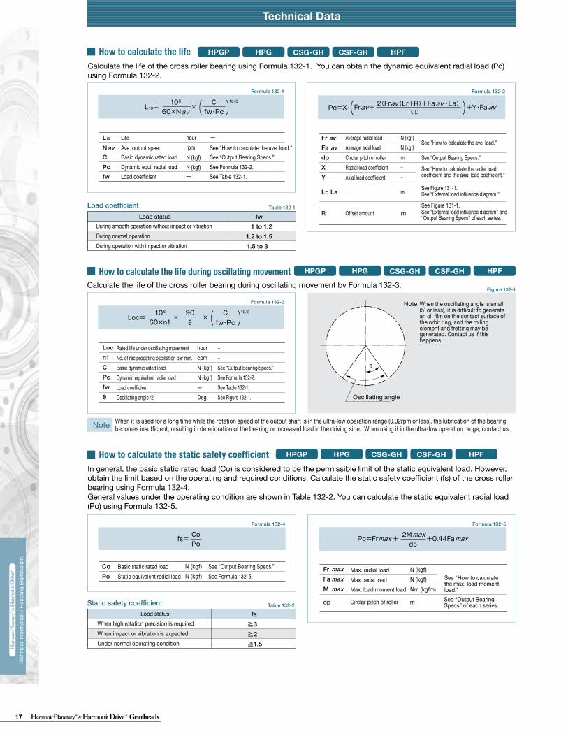
17 Gearheads
Technical DataTechnical Data Technical Data
230 231
Tech
nica
l Inf
orm
atio
n / H
andl
ing
Expl
anat
ion
Tech
nica
l Inf
orm
atio
n / H
andl
ing
Expl
anat
ion
HPG HPF
Calculate:Maximum load moment load (Mi max)Maximum load axial load (Fai max)Maximum load radial load (Fri max)
Calculate:Average moment load (Mi av)Average axial load (Fai av) Average input speed (Ni av)
Maximum load moment load (Mi max) ≦ Permissible moment load (Mc)Maximum load axial load (Fai max) ≦ Permissible axial load (Fac)Maximum load radial load (Fri max) ≦ Permissible radial load (Frc)
Calculate the life and check it.
(2) Checking the life
(1) Checking maximum load
Time: t
Time: t
n1
n2
n3
M1
M2
M3
M4
n4
t1 t2 t3 t4
L10
NiCrPci
LifeAverage input rotational speedBasic dynamic rated loadDynamic equivalent radial load
HourrpmN (kgf)N
av
111420325065
0.137 × Mi av + 1.232 × Fai av0.444 × Mi av + 1.426 × Fai av
0.041 × Mi av + 1.232 × Fai av
0.109 × Mi av + 1.232 × Fai av0.071 × Mi av + 1.232 × Fai av0.053 × Mi av + 1.232 × Fai av
maxmax
Fai
Lri
Fri
Lai
111420325065
111420325065
2532
2532
*1 The allowable axial load is the tolerance of an axial load applied to the shaft center.*2 The allowable radial load of HPG series is the tolerance of a radial load applied to the shaft length center.*3 The allowable radial load of HPG series is the tolerance of a radial load applied to the point of 20 mm from the shaft edge (input flange edge).
2532 106 × Mi av + 2.7 × Fai av
121 × Mi av + 2.7 × Fai av
Fai
Fri
Lai
Lri
Check the maximum load and life of the bearing on the input side if the reducer is an HPG input shaft unit or an HPF hollow shaft unit.
FriFaiLri,Lai
The specification of the input side main bearing of the input shaft unit is shown below.
If moment load and axial load fluctuate, they should be converted into the average load to check the life of the bearing.
Calculate the bearing life according to Calculation Formula 132-5 and check the life.
Specification of input shaft bearing
Specification of input shaft bearing
Table 133-1
Table 134-1
Table 134-2
Figure 134-1
Formula 134-2
Formula 134-3
Formula 134-4
Graph 134-1
Formula 134-5
Table 133-2
Size
Table 133-3
Table 133-4
〔Note: Table 133-2 and 133-4〕
External load influence diagram
Dynamic equivalent radial load
Size
Dynamic equivalent radial load
HPG HPF
HPG
HPF
HPG HPF
HPG
HPF
Pci
N270058009700
225003550051000
kgf275590990
230036005200
N127031505600148002510039500
kgf129320570151025604050
Nm0.166.313.544.496.9210
kgfm0.0160.641.384.539.8821.4
N2456571206328555408600
kgf2567123335565878
N20.6500902197032265267
kgf2.15192
201329537
N1450029700
kgf14803030
N1010020100
kgf10302050
Nm1019
kgfm1.021.93
N15383263
kgf157333
N522966
kgf53.298.5
Pci
HPG HPF
Formula 134-1
Checking procedure
Specification of input shaft bearing
SizeBasic rated load
Basic dynamic rated load Cr Basic static rated load Cor
SizeAllowable moment load Mc Allowable axial load Fac *1 Allowable radial load Frc *2
SizeBasic rated load
Basic dynamic rated load Cr Basic static rated load Cor
SizeAllowable moment load Mc Allowable axial load Fac *1 Allowable radial load Frc *3
Calculating maximum load moment load to input shaft
How to calculate average load(Average moment load, average axial load, average input rotational frequency)
Mi max ≦ Mc (Permissible moment load)Fai max ≦ Fac (Permissible axial load)
Max. radial loadMax. axial load————
N (kgf)N (kgf)m
See Fig. 134-1.See Fig. 134-1.See Fig. 134-1.
The maximum load moment load (Mi max ) is calculated as follows.Check that the following formulas are established in all circumstances:
Inpu
t spe
edM
omen
t loa
d
How to calculate the average moment load (Miav )
How to calculate the average axial load (Faiav)
How to calculate the average output rotational frequency (Niav)
Calculating life of input side bearing
Miav Average moment load Nm (kgfm) See Formula 134-2Faiav Average axial load N (kgf) See Formula 134-3
See Formula 134-4See Table 133-1 and -3See Table 134-1 and -2
Input Bearing Specifications and Checking Procedure
228 229
Tech
nica
l Inf
orm
atio
n / H
andl
ing
Expl
anat
ion
Tech
nica
l Inf
orm
atio
n / H
andl
ing
Expl
anat
ion
Technical Data Technical Data
HPG HPFCSG-GH CSF-GHHPGPHow to calculate the maximum load moment load
How to calculate the radial load coefficient and the axial load coefficient
The radial load coefficient (X) and the axial load coefficient (Y)
HPGHPF
CSG-GHCSF-GH
HPG HPFCSG-GH CSF-GH
HPG HPFCSG-GH CSF-GHHPGP
HPG HPFCSG-GH CSF-GHHPGP
HPGP
HPGHPF
CSG-GHCSF-GH
HPGP
HPGP
Formula 131-1
Formula 131-3
Formula 131-4
Formula 131-5
Formula 131-2
Figure 131-1
Load coefficient
Static safety coefficient
Formula 132-1
Table 132-1
Table 132-2
Formula 132-3
Figure 132-1
Formula 132-4 Formula 132-5
Formula 132-2
Note
Note that the maximum axial load within the t1 section is Fr1 and the maximum axial load within the t3 section is Fr3.
Note that the maximum axial load within the t1 section is Fr1 and the maximum axial load within the t3 section is Fr3.
Fr1
Fr2
Fr4
Fa1
Fa2
Fa4
Fa3t1 t2 t3 t4
n1
n2
n4
n3
Fr3
Time
Time
Time
N (kgf)
N (kgf)
m
m
M =Fr (Lr+R)+Fa ・ Lamax max max
N (kgf)
N (kgf)
m
m
m
Fr
Fa
Lr, La
R
dp
av
av
1
0.67 0.67
0.45≦1.5Fa
Fr +2(Fr (Lr+R)+Fa ・La)/dpavav avav
>1.5FaFr +2(Fr (Lr+R)+Fa ・La)/dpavav av
av
hourrpmN (kgf)N (kgf)
N (kgf)N (kgf)m––
m
FrFadpXY
Lr, La
avav
Locn1CPcfwθ
Rated life under oscillating movementNo. of reciprocating oscillation per min.Basic dynamic rated loadDynamic equivalent radial load Load coefficientOscillating angle /2
hourcpmN (kgf)N (kgf)—Deg.
−−See “Output Bearing Specs.” See Formula 132-2.See Table 132-1.See Figure 132-1.
Basic static rated loadStatic equivalent radial load
N (kgf)N (kgf)
See “Output Bearing Specs.” See Formula 132-5.
FrFaM
N (kgf)N (kgf)Nm (kgfm)
See “Output Bearing Specs” of each series. mdp
maxmaxmax
When it is used for a long time while the rotation speed of the output shaft is in the ultra-low operation range (0.02rpm or less), the lubrication of the bearing becomes insufficient, resulting in deterioration of the bearing or increased load in the driving side. When using it in the ultra-low operation range, contact us.
See “Specification of main bearing” of each series
See “Output Shaft Bearing Specifications” of each series.
During smooth operation without impact or vibrationDuring normal operationDuring operation with impact or vibration
When high rotation precision is requiredWhen impact or vibration is expectedUnder normal operating condition
≧3≧2≧1.5
How to obtain the average radial load (Fr )av
How to obtain the average axial load (Fa )av
How to obtain the average output rotational frequency (N )av
Fr
Fa
Lr, La
R
max
max
X Y
Calculate the life of the cross roller bearing during oscillating movement by Formula 132-3.
If the radial load and the axial load fluctuate, they should be converted into the average load to check the life of the cross roller bearing.
Formula
L10
NavCPcfw
See “How to calculate the ave. load.”See “Output Bearing Specs.” See Formula 132-2.See Table 132-1.
LifeAve. output speedBasic dynamic rated loadDynamic equi. radial loadLoad coefficient
Load status fw 1 to 1.21.2 to 1.51.5 to 3
fs
CoPo
dp
RLrFa
La
Fr
θ
Oscillating angle
Note:
maxmax
Max. radial load
Max. axial load
Offset amount
See Fig. 131-1.
See Fig. 131-1.
See Fig. 131-1.
See Fig. 131-1.
Average radial load
Average axial load
Offset amount
Circlar pitch of roller
See “How to obtain the average load.”
See “How to obtain the average load.”
See Fig. 131-1.
See Fig. 131-1.
See “Output Shaft Bearing Specifications” of each series. See Fig. 131-1.
How to calculate the average load (Average radial load, average axial load, average output rotational frequency)
Radi
al lo
adAx
ial l
oad
Outp
ut ro
tatio
nal
frequ
ency
Load
Radial load
Axial load
Calculate the life of the cross roller bearing using Formula 132-1. You can obtain the dynamic equivalent radial load (Pc) using Formula 132-2.
How to calculate the life
How to calculate the life during oscillating movement
How to calculate the static safety coefficient
Average radial loadAverage axial loadCirclar pitch of roller Radial load coefficientAxial load coefficient
Offset amount mR
See "How to calculate the ave. load."
See “Output Bearing Specs.”
See “How to calculate the radial load coefficient and the axial load coefficient.”
See Figure 131-1. See “External load influence diagram.”
See Figure 131-1.See “External load influence diagram” and “Output Bearing Specs” of each series.
When the oscillating angle is small (5˚ or less), it is difficult to generate an oil film on the contact surface of the orbit ring, and the rolling element and fretting may be generated. Contact us if this happens.
In general, the basic static rated load (Co) is considered to be the permissible limit of the static equivalent load. However, obtain the limit based on the operating and required conditions. Calculate the static safety coefficient (fs) of the cross roller bearing using Formula 132-4. General values under the operating condition are shown in Table 132-2. You can calculate the static equivalent radial load (Po) using Formula 132-5.
Load status
Max. radial loadMax. axial load See “How to calculate
the max. load moment load.”Max. load moment load
Circlar pitch of roller
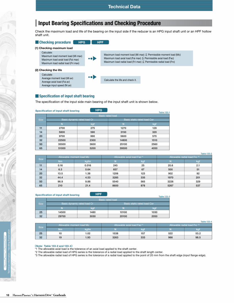
18 Gearheads
Technical DataTechnical Data Technical Data
230 231
Tech
nica
l Inf
orm
atio
n / H
andl
ing
Expl
anat
ion
Tech
nica
l Inf
orm
atio
n / H
andl
ing
Expl
anat
ion
HPG HPF
Calculate:Maximum load moment load (Mi max)Maximum load axial load (Fai max)Maximum load radial load (Fri max)
Calculate:Average moment load (Mi av)Average axial load (Fai av) Average input speed (Ni av)
Maximum load moment load (Mi max) ≦ Permissible moment load (Mc)Maximum load axial load (Fai max) ≦ Permissible axial load (Fac)Maximum load radial load (Fri max) ≦ Permissible radial load (Frc)
Calculate the life and check it.
(2) Checking the life
(1) Checking maximum load
Time: t
Time: t
n1
n2
n3
M1
M2
M3
M4
n4
t1 t2 t3 t4
L10
NiCrPci
LifeAverage input rotational speedBasic dynamic rated loadDynamic equivalent radial load
HourrpmN (kgf)N
av
111420325065
0.137 × Mi av + 1.232 × Fai av0.444 × Mi av + 1.426 × Fai av
0.041 × Mi av + 1.232 × Fai av
0.109 × Mi av + 1.232 × Fai av0.071 × Mi av + 1.232 × Fai av0.053 × Mi av + 1.232 × Fai av
maxmax
Fai
Lri
Fri
Lai
111420325065
111420325065
2532
2532
*1 The allowable axial load is the tolerance of an axial load applied to the shaft center.*2 The allowable radial load of HPG series is the tolerance of a radial load applied to the shaft length center.*3 The allowable radial load of HPG series is the tolerance of a radial load applied to the point of 20 mm from the shaft edge (input flange edge).
2532 106 × Mi av + 2.7 × Fai av
121 × Mi av + 2.7 × Fai av
Fai
Fri
Lai
Lri
Check the maximum load and life of the bearing on the input side if the reducer is an HPG input shaft unit or an HPF hollow shaft unit.
FriFaiLri,Lai
The specification of the input side main bearing of the input shaft unit is shown below.
If moment load and axial load fluctuate, they should be converted into the average load to check the life of the bearing.
Calculate the bearing life according to Calculation Formula 132-5 and check the life.
Specification of input shaft bearing
Specification of input shaft bearing
Table 133-1
Table 134-1
Table 134-2
Figure 134-1
Formula 134-2
Formula 134-3
Formula 134-4
Graph 134-1
Formula 134-5
Table 133-2
Size
Table 133-3
Table 133-4
〔Note: Table 133-2 and 133-4〕
External load influence diagram
Dynamic equivalent radial load
Size
Dynamic equivalent radial load
HPG HPF
HPG
HPF
HPG HPF
HPG
HPF
Pci
N270058009700
225003550051000
kgf275590990
230036005200
N127031505600148002510039500
kgf129320570151025604050
Nm0.166.313.544.496.9210
kgfm0.0160.641.384.539.8821.4
N2456571206328555408600
kgf2567123335565878
N20.6500902197032265267
kgf2.15192
201329537
N1450029700
kgf14803030
N1010020100
kgf10302050
Nm1019
kgfm1.021.93
N15383263
kgf157333
N522966
kgf53.298.5
Pci
HPG HPF
Formula 134-1
Checking procedure
Specification of input shaft bearing
SizeBasic rated load
Basic dynamic rated load Cr Basic static rated load Cor
SizeAllowable moment load Mc Allowable axial load Fac *1 Allowable radial load Frc *2
SizeBasic rated load
Basic dynamic rated load Cr Basic static rated load Cor
SizeAllowable moment load Mc Allowable axial load Fac *1 Allowable radial load Frc *3
Calculating maximum load moment load to input shaft
How to calculate average load(Average moment load, average axial load, average input rotational frequency)
Mi max ≦ Mc (Permissible moment load)Fai max ≦ Fac (Permissible axial load)
Max. radial loadMax. axial load————
N (kgf)N (kgf)m
See Fig. 134-1.See Fig. 134-1.See Fig. 134-1.
The maximum load moment load (Mi max ) is calculated as follows.Check that the following formulas are established in all circumstances:
Inpu
t spe
edM
omen
t loa
d
How to calculate the average moment load (Miav )
How to calculate the average axial load (Faiav)
How to calculate the average output rotational frequency (Niav)
Calculating life of input side bearing
Miav Average moment load Nm (kgfm) See Formula 134-2Faiav Average axial load N (kgf) See Formula 134-3
See Formula 134-4See Table 133-1 and -3See Table 134-1 and -2
Input Bearing Specifications and Checking Procedure
Technical Data Technical Data
230 231
Tech
nica
l Inf
orm
atio
n / H
andl
ing
Expl
anat
ion
Tech
nica
l Inf
orm
atio
n / H
andl
ing
Expl
anat
ion
HPG HPF
Calculate:Maximum load moment load (Mi max)Maximum load axial load (Fai max)Maximum load radial load (Fri max)
Calculate:Average moment load (Mi av)Average axial load (Fai av) Average input speed (Ni av)
Maximum load moment load (Mi max) ≦ Permissible moment load (Mc)Maximum load axial load (Fai max) ≦ Permissible axial load (Fac)Maximum load radial load (Fri max) ≦ Permissible radial load (Frc)
Calculate the life and check it.
(2) Checking the life
(1) Checking maximum load
Time: t
Time: t
n1
n2
n3
M1
M2
M3
M4
n4
t1 t2 t3 t4
L10
NiCrPci
LifeAverage input rotational speedBasic dynamic rated loadDynamic equivalent radial load
HourrpmN (kgf)N
av
111420325065
0.137 × Mi av + 1.232 × Fai av0.444 × Mi av + 1.426 × Fai av
0.041 × Mi av + 1.232 × Fai av
0.109 × Mi av + 1.232 × Fai av0.071 × Mi av + 1.232 × Fai av0.053 × Mi av + 1.232 × Fai av
maxmax
Fai
Lri
Fri
Lai
111420325065
111420325065
2532
2532
*1 The allowable axial load is the tolerance of an axial load applied to the shaft center.*2 The allowable radial load of HPG series is the tolerance of a radial load applied to the shaft length center.*3 The allowable radial load of HPG series is the tolerance of a radial load applied to the point of 20 mm from the shaft edge (input flange edge).
2532 106 × Mi av + 2.7 × Fai av
121 × Mi av + 2.7 × Fai av
Fai
Fri
Lai
Lri
Check the maximum load and life of the bearing on the input side if the reducer is an HPG input shaft unit or an HPF hollow shaft unit.
FriFaiLri,Lai
The specification of the input side main bearing of the input shaft unit is shown below.
If moment load and axial load fluctuate, they should be converted into the average load to check the life of the bearing.
Calculate the bearing life according to Calculation Formula 132-5 and check the life.
Specification of input shaft bearing
Specification of input shaft bearing
Table 133-1
Table 134-1
Table 134-2
Figure 134-1
Formula 134-2
Formula 134-3
Formula 134-4
Graph 134-1
Formula 134-5
Table 133-2
Size
Table 133-3
Table 133-4
〔Note: Table 133-2 and 133-4〕
External load influence diagram
Dynamic equivalent radial load
Size
Dynamic equivalent radial load
HPG HPF
HPG
HPF
HPG HPF
HPG
HPF
Pci
N270058009700
225003550051000
kgf275590990
230036005200
N127031505600148002510039500
kgf129320570151025604050
Nm0.166.313.544.496.9210
kgfm0.0160.641.384.539.8821.4
N2456571206328555408600
kgf2567123335565878
N20.6500902197032265267
kgf2.15192
201329537
N1450029700
kgf14803030
N1010020100
kgf10302050
Nm1019
kgfm1.021.93
N15383263
kgf157333
N522966
kgf53.298.5
Pci
HPG HPF
Formula 134-1
Checking procedure
Specification of input shaft bearing
SizeBasic rated load
Basic dynamic rated load Cr Basic static rated load Cor
SizeAllowable moment load Mc Allowable axial load Fac *1 Allowable radial load Frc *2
SizeBasic rated load
Basic dynamic rated load Cr Basic static rated load Cor
SizeAllowable moment load Mc Allowable axial load Fac *1 Allowable radial load Frc *3
Calculating maximum load moment load to input shaft
How to calculate average load(Average moment load, average axial load, average input rotational frequency)
Mi max ≦ Mc (Permissible moment load)Fai max ≦ Fac (Permissible axial load)
Max. radial loadMax. axial load————
N (kgf)N (kgf)m
See Fig. 134-1.See Fig. 134-1.See Fig. 134-1.
The maximum load moment load (Mi max ) is calculated as follows.Check that the following formulas are established in all circumstances:
Inpu
t spe
edM
omen
t loa
d
How to calculate the average moment load (Miav )
How to calculate the average axial load (Faiav)
How to calculate the average output rotational frequency (Niav)
Calculating life of input side bearing
Miav Average moment load Nm (kgfm) See Formula 134-2Faiav Average axial load N (kgf) See Formula 134-3
See Formula 134-4See Table 133-1 and -3See Table 134-1 and -2
Input Bearing Specifications and Checking Procedure
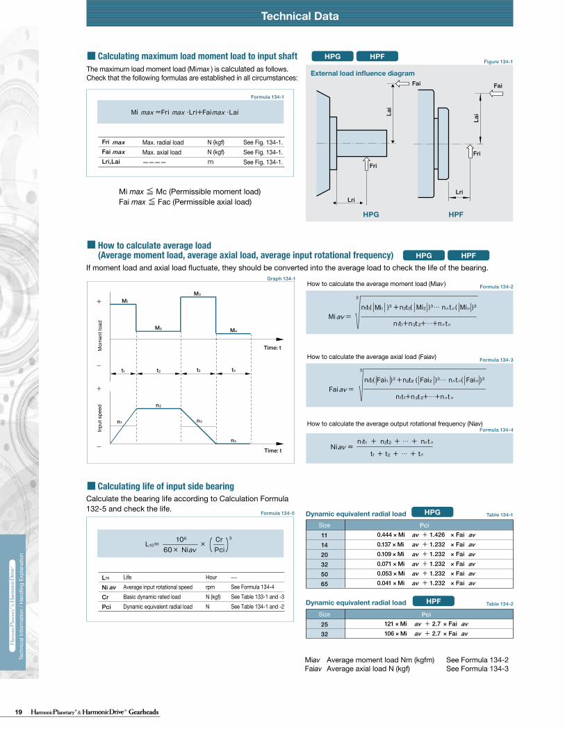
19 Gearheads
Technical DataTechnical Data Technical Data
230 231
Tech
nica
l Inf
orm
atio
n / H
andl
ing
Expl
anat
ion
Tech
nica
l Inf
orm
atio
n / H
andl
ing
Expl
anat
ion
HPG HPF
Calculate:Maximum load moment load (Mi max)Maximum load axial load (Fai max)Maximum load radial load (Fri max)
Calculate:Average moment load (Mi av)Average axial load (Fai av) Average input speed (Ni av)
Maximum load moment load (Mi max) ≦ Permissible moment load (Mc)Maximum load axial load (Fai max) ≦ Permissible axial load (Fac)Maximum load radial load (Fri max) ≦ Permissible radial load (Frc)
Calculate the life and check it.
(2) Checking the life
(1) Checking maximum load
Time: t
Time: t
n1
n2
n3
M1
M2
M3
M4
n4
t1 t2 t3 t4
L10
NiCrPci
LifeAverage input rotational speedBasic dynamic rated loadDynamic equivalent radial load
HourrpmN (kgf)N
av
111420325065
0.137 × Mi av + 1.232 × Fai av0.444 × Mi av + 1.426 × Fai av
0.041 × Mi av + 1.232 × Fai av
0.109 × Mi av + 1.232 × Fai av0.071 × Mi av + 1.232 × Fai av0.053 × Mi av + 1.232 × Fai av
maxmax
Fai
Lri
Fri
Lai
111420325065
111420325065
2532
2532
*1 The allowable axial load is the tolerance of an axial load applied to the shaft center.*2 The allowable radial load of HPG series is the tolerance of a radial load applied to the shaft length center.*3 The allowable radial load of HPG series is the tolerance of a radial load applied to the point of 20 mm from the shaft edge (input flange edge).
2532 106 × Mi av + 2.7 × Fai av
121 × Mi av + 2.7 × Fai av
Fai
Fri
Lai
Lri
Check the maximum load and life of the bearing on the input side if the reducer is an HPG input shaft unit or an HPF hollow shaft unit.
FriFaiLri,Lai
The specification of the input side main bearing of the input shaft unit is shown below.
If moment load and axial load fluctuate, they should be converted into the average load to check the life of the bearing.
Calculate the bearing life according to Calculation Formula 132-5 and check the life.
Specification of input shaft bearing
Specification of input shaft bearing
Table 133-1
Table 134-1
Table 134-2
Figure 134-1
Formula 134-2
Formula 134-3
Formula 134-4
Graph 134-1
Formula 134-5
Table 133-2
Size
Table 133-3
Table 133-4
〔Note: Table 133-2 and 133-4〕
External load influence diagram
Dynamic equivalent radial load
Size
Dynamic equivalent radial load
HPG HPF
HPG
HPF
HPG HPF
HPG
HPF
Pci
N270058009700
225003550051000
kgf275590990
230036005200
N127031505600148002510039500
kgf129320570151025604050
Nm0.166.313.544.496.9210
kgfm0.0160.641.384.539.8821.4
N2456571206328555408600
kgf2567123335565878
N20.6500902197032265267
kgf2.15192
201329537
N1450029700
kgf14803030
N1010020100
kgf10302050
Nm1019
kgfm1.021.93
N15383263
kgf157333
N522966
kgf53.298.5
Pci
HPG HPF
Formula 134-1
Checking procedure
Specification of input shaft bearing
SizeBasic rated load
Basic dynamic rated load Cr Basic static rated load Cor
SizeAllowable moment load Mc Allowable axial load Fac *1 Allowable radial load Frc *2
SizeBasic rated load
Basic dynamic rated load Cr Basic static rated load Cor
SizeAllowable moment load Mc Allowable axial load Fac *1 Allowable radial load Frc *3
Calculating maximum load moment load to input shaft
How to calculate average load(Average moment load, average axial load, average input rotational frequency)
Mi max ≦ Mc (Permissible moment load)Fai max ≦ Fac (Permissible axial load)
Max. radial loadMax. axial load————
N (kgf)N (kgf)m
See Fig. 134-1.See Fig. 134-1.See Fig. 134-1.
The maximum load moment load (Mi max ) is calculated as follows.Check that the following formulas are established in all circumstances:
Inpu
t spe
edM
omen
t loa
d
How to calculate the average moment load (Miav )
How to calculate the average axial load (Faiav)
How to calculate the average output rotational frequency (Niav)
Calculating life of input side bearing
Miav Average moment load Nm (kgfm) See Formula 134-2Faiav Average axial load N (kgf) See Formula 134-3
See Formula 134-4See Table 133-1 and -3See Table 134-1 and -2
Input Bearing Specifications and Checking Procedure
Technical Data Technical Data
230 231
Tech
nica
l Inf
orm
atio
n / H
andl
ing
Expl
anat
ion
Tech
nica
l Inf
orm
atio
n / H
andl
ing
Expl
anat
ion
HPG HPF
Calculate:Maximum load moment load (Mi max)Maximum load axial load (Fai max)Maximum load radial load (Fri max)
Calculate:Average moment load (Mi av)Average axial load (Fai av) Average input speed (Ni av)
Maximum load moment load (Mi max) ≦ Permissible moment load (Mc)Maximum load axial load (Fai max) ≦ Permissible axial load (Fac)Maximum load radial load (Fri max) ≦ Permissible radial load (Frc)
Calculate the life and check it.
(2) Checking the life
(1) Checking maximum load
Time: t
Time: t
n1
n2
n3
M1
M2
M3
M4
n4
t1 t2 t3 t4
L10
NiCrPci
LifeAverage input rotational speedBasic dynamic rated loadDynamic equivalent radial load
HourrpmN (kgf)N
av
111420325065
0.137 × Mi av + 1.232 × Fai av0.444 × Mi av + 1.426 × Fai av
0.041 × Mi av + 1.232 × Fai av
0.109 × Mi av + 1.232 × Fai av0.071 × Mi av + 1.232 × Fai av0.053 × Mi av + 1.232 × Fai av
maxmax
Fai
Lri
Fri
Lai
111420325065
111420325065
2532
2532
*1 The allowable axial load is the tolerance of an axial load applied to the shaft center.*2 The allowable radial load of HPG series is the tolerance of a radial load applied to the shaft length center.*3 The allowable radial load of HPG series is the tolerance of a radial load applied to the point of 20 mm from the shaft edge (input flange edge).
2532 106 × Mi av + 2.7 × Fai av
121 × Mi av + 2.7 × Fai av
Fai
Fri
Lai
Lri
Check the maximum load and life of the bearing on the input side if the reducer is an HPG input shaft unit or an HPF hollow shaft unit.
FriFaiLri,Lai
The specification of the input side main bearing of the input shaft unit is shown below.
If moment load and axial load fluctuate, they should be converted into the average load to check the life of the bearing.
Calculate the bearing life according to Calculation Formula 132-5 and check the life.
Specification of input shaft bearing
Specification of input shaft bearing
Table 133-1
Table 134-1
Table 134-2
Figure 134-1
Formula 134-2
Formula 134-3
Formula 134-4
Graph 134-1
Formula 134-5
Table 133-2
Size
Table 133-3
Table 133-4
〔Note: Table 133-2 and 133-4〕
External load influence diagram
Dynamic equivalent radial load
Size
Dynamic equivalent radial load
HPG HPF
HPG
HPF
HPG HPF
HPG
HPF
Pci
N270058009700
225003550051000
kgf275590990
230036005200
N127031505600148002510039500
kgf129320570151025604050
Nm0.166.313.544.496.9210
kgfm0.0160.641.384.539.8821.4
N2456571206328555408600
kgf2567123335565878
N20.6500902197032265267
kgf2.15192
201329537
N1450029700
kgf14803030
N1010020100
kgf10302050
Nm1019
kgfm1.021.93
N15383263
kgf157333
N522966
kgf53.298.5
Pci
HPG HPF
Formula 134-1
Checking procedure
Specification of input shaft bearing
SizeBasic rated load
Basic dynamic rated load Cr Basic static rated load Cor
SizeAllowable moment load Mc Allowable axial load Fac *1 Allowable radial load Frc *2
SizeBasic rated load
Basic dynamic rated load Cr Basic static rated load Cor
SizeAllowable moment load Mc Allowable axial load Fac *1 Allowable radial load Frc *3
Calculating maximum load moment load to input shaft
How to calculate average load(Average moment load, average axial load, average input rotational frequency)
Mi max ≦ Mc (Permissible moment load)Fai max ≦ Fac (Permissible axial load)
Max. radial loadMax. axial load————
N (kgf)N (kgf)m
See Fig. 134-1.See Fig. 134-1.See Fig. 134-1.
The maximum load moment load (Mi max ) is calculated as follows.Check that the following formulas are established in all circumstances:
Inpu
t spe
edM
omen
t loa
d
How to calculate the average moment load (Miav )
How to calculate the average axial load (Faiav)
How to calculate the average output rotational frequency (Niav)
Calculating life of input side bearing
Miav Average moment load Nm (kgfm) See Formula 134-2Faiav Average axial load N (kgf) See Formula 134-3
See Formula 134-4See Table 133-1 and -3See Table 134-1 and -2
Input Bearing Specifications and Checking Procedure
20 GearheadsRev 02-15
Group Companies Harmonic Drive Systems, Inc. 6-25-3 Minami-Ohi, Shinagawa-ku Tokyo 141-0013, Japan
Harmonic Drive AG Hoenbergstrasse, 14, D-6555 Limburg/Lahn Germany
Harmonic Drive® and HarmonicPlanetary® are registered trademarks and Quick Connect is a trademark of Harmonic Drive LLC. All other trade-marks are property of their respective owners.
Harmonic Drive LLCBoston US Headquarters247 Lynnfield Street Peabody, MA 01960
New York Sales Office100 Motor ParkwaySuite 116Hauppauge, NY 11788
California Sales Office333 W. San Carlos Street Suite 1070San Jose, CA 95110
Chicago Sales Office137 N. Oak Park Ave., Suite 410Oak Park, IL 60301
T: 800.921.3332 T: 978.532.1800 F: 978.532.9406
www.HarmonicDrive.net