A novel approach to aeroelastic design of … · Dynamic Aeroelasticity: Flutter ... backlash [Van...
36
A novel approach to aeroelastic design of unconventional configurations Merging FSI solvers and LFT/μ tools Rauno Cavallaro, Rocco Bombardieri. Andres Marcos, Andrea Iannelli.
Transcript of A novel approach to aeroelastic design of … · Dynamic Aeroelasticity: Flutter ... backlash [Van...
A novel approach to aeroelastic
design of unconventional
configurationsMerging FSI solvers and LFT/μ tools
Rauno Cavallaro, Rocco Bombardieri.
Andres Marcos, Andrea Iannelli.
AGENDA
➢ Introduction
➢ Unconventional Aircraft Configuration: the Box
Wing/PrandtlPlane case
➢ CSHELL: An Inhouse Aeroelastic Computational Tool
➢ UC3M – UoB Collaboration: Preliminary Results
➢ Conclusions
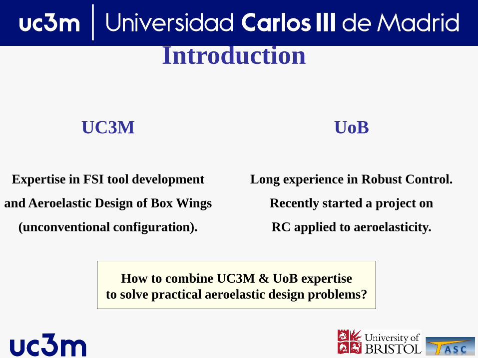
Introduction
UC3M
Expertise in FSI tool development
and Aeroelastic Design of Box Wings
(unconventional configuration).
UoB
Long experience in Robust Control.
Recently started a project on
RC applied to aeroelasticity.
How to combine UC3M & UoB expertise
to solve practical aeroelastic design problems?
AGENDA
➢ Introduction
➢Unconventional Aircraft Configuration: the Box
Wing/PrandtlPlane case
➢ CSHELL: An Inhouse Aeroelastic Computational Tool
➢ UC3M – UoB Collaboration: Preliminary Results
➢ Conclusions
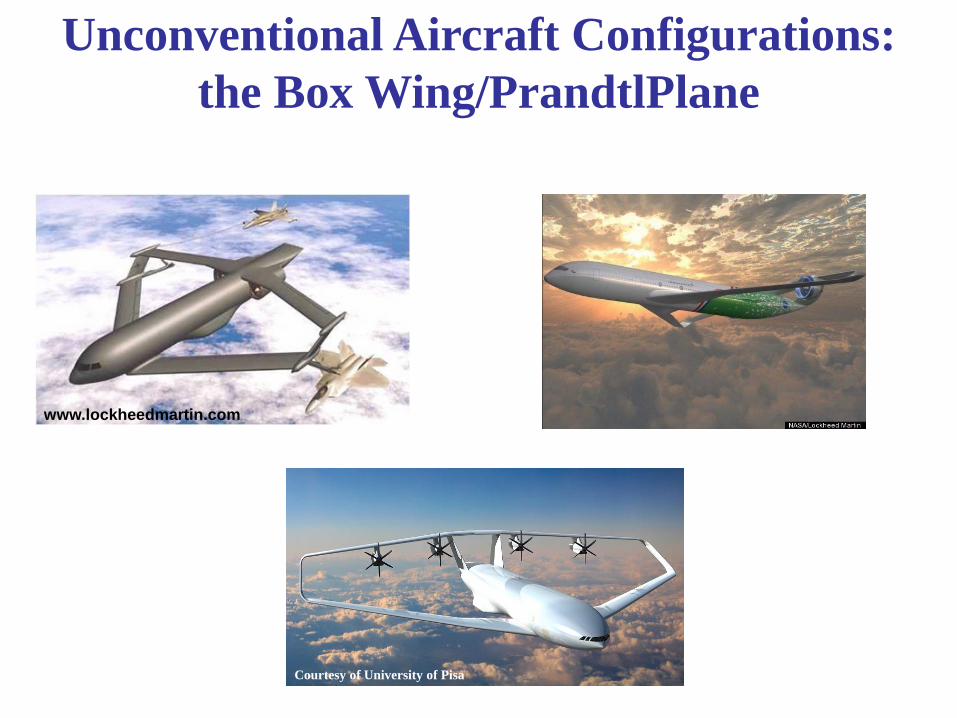
Unconventional Aircraft Configurations:
the Box Wing/PrandtlPlane
Courtesy of University of Pisa
www.lockheedmartin.com
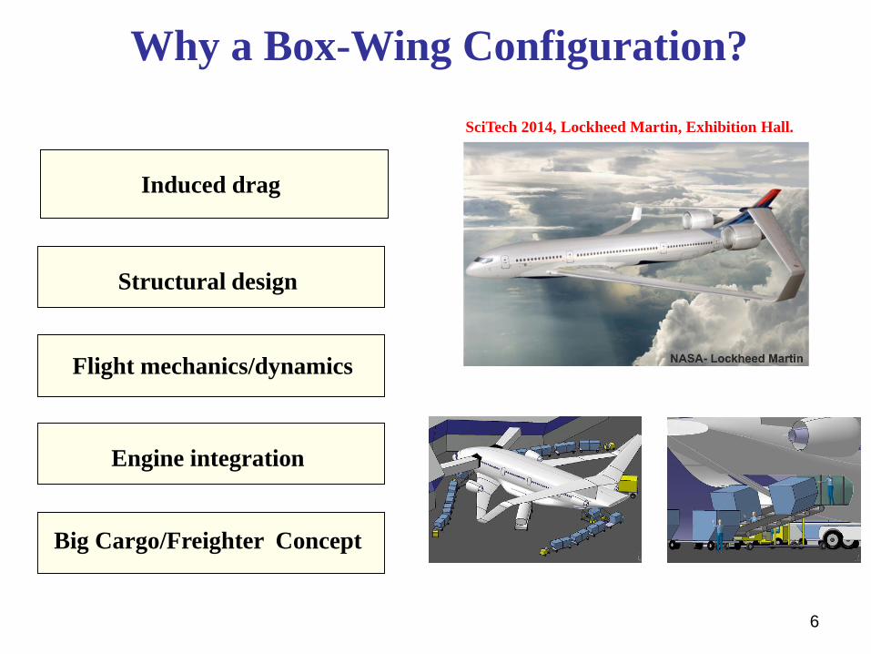
Why a Box-Wing Configuration?
6
Induced drag
Structural design
Flight mechanics/dynamics
Engine integration
Big Cargo/Freighter Concept
SciTech 2014, Lockheed Martin, Exhibition Hall.
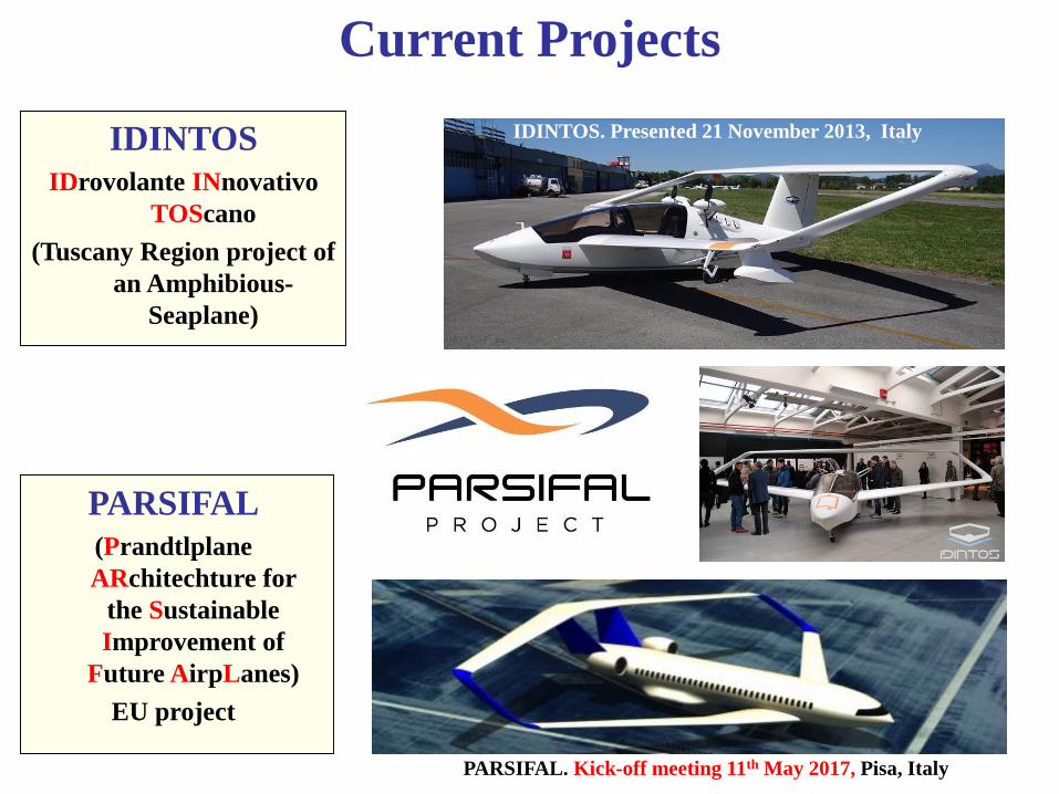
Current Projects
7
www.nasa.gov
PARSIFAL
(Prandtlplane
ARchitechture for
the Sustainable
Improvement of
Future AirpLanes)
EU project
PARSIFAL. Kick-off meeting 11th May 2017, Pisa, Italy
IDINTOS. Presented 21 November 2013, ItalyIDINTOS
IDrovolante INnovativo
TOScano
(Tuscany Region project of
an Amphibious-
Seaplane)
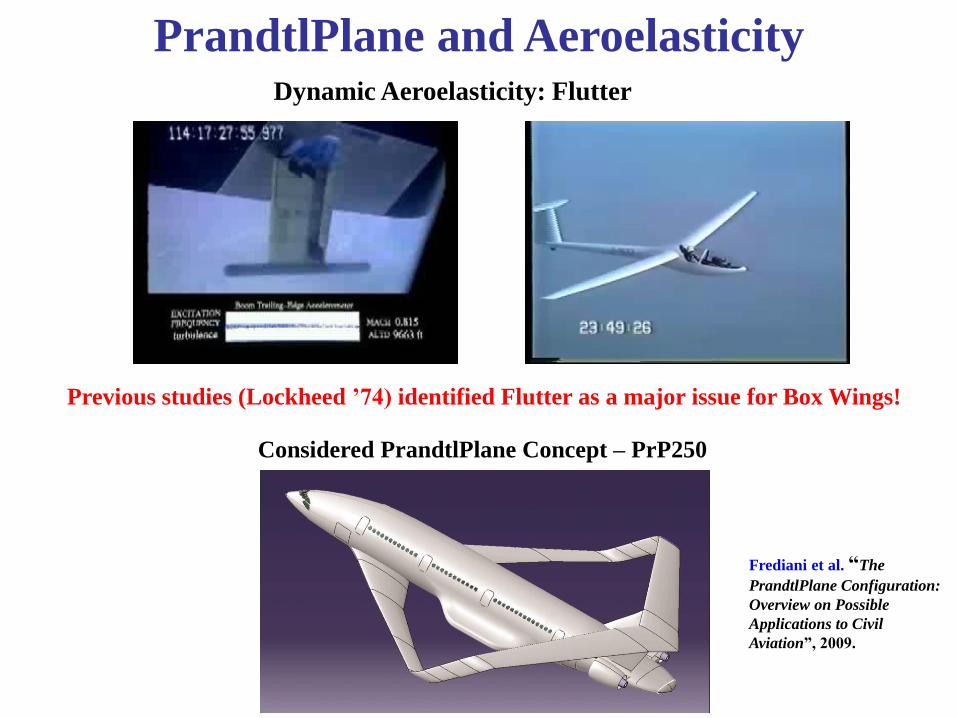
PrandtlPlane and Aeroelasticity
Frediani et al. “The
PrandtlPlane Configuration:
Overview on Possible
Applications to Civil
Aviation”, 2009.
Dynamic Aeroelasticity: Flutter
Considered PrandtlPlane Concept – PrP250
Previous studies (Lockheed ’74) identified Flutter as a major issue for Box Wings!
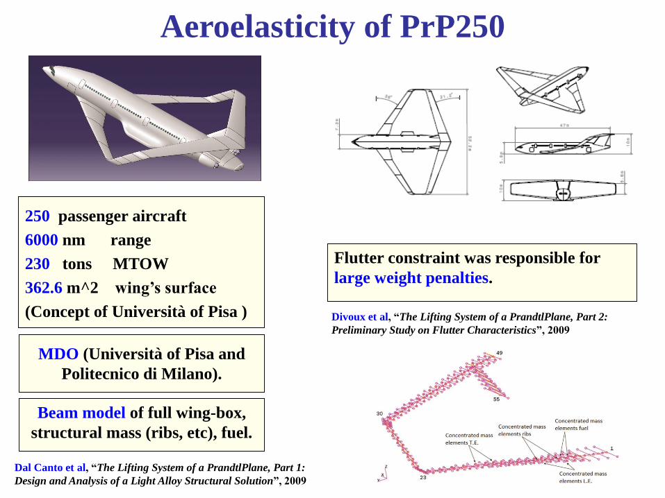
250 passenger aircraft
6000 nm range
230 tons MTOW
362.6 m^2 wing’s surface
(Concept of Università of Pisa )
MDO (Università of Pisa and
Politecnico di Milano).
Beam model of full wing-box,
structural mass (ribs, etc), fuel.
Aeroelasticity of PrP250
Flutter constraint was responsible for
large weight penalties.
Dal Canto et al, “The Lifting System of a PrandtlPlane, Part 1:
Design and Analysis of a Light Alloy Structural Solution”, 2009
Divoux et al, “The Lifting System of a PrandtlPlane, Part 2:
Preliminary Study on Flutter Characteristics”, 2009
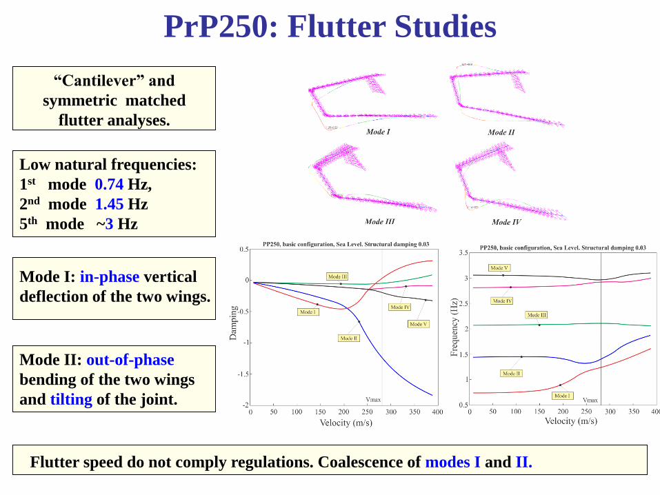
PrP250: Flutter Studies
“Cantilever” and
symmetric matched
flutter analyses.
Low natural frequencies:
1st mode 0.74 Hz,
2nd mode 1.45 Hz
5th mode ~3 Hz
Mode I: in-phase vertical
deflection of the two wings.
Mode II: out-of-phase
bending of the two wings
and tilting of the joint.
Flutter speed do not comply regulations. Coalescence of modes I and II.
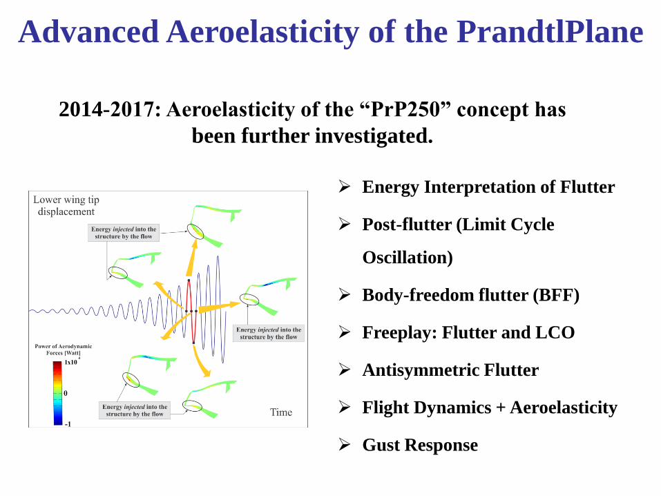
Advanced Aeroelasticity of the PrandtlPlane
2014-2017: Aeroelasticity of the “PrP250” concept has
been further investigated.
➢ Energy Interpretation of Flutter
➢ Post-flutter (Limit Cycle
Oscillation)
➢ Body-freedom flutter (BFF)
➢ Freeplay: Flutter and LCO
➢ Antisymmetric Flutter
➢ Flight Dynamics + Aeroelasticity
➢ Gust Response
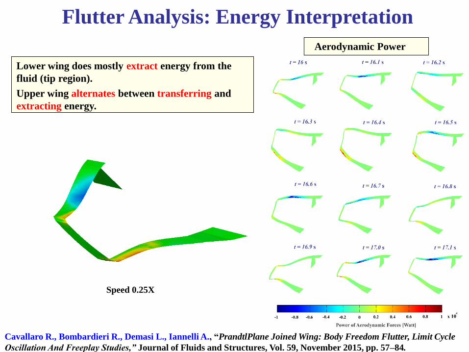
Flutter Analysis: Energy Interpretation
Aerodynamic Power
Speed 0.25X
Lower wing does mostly extract energy from the
fluid (tip region).
Upper wing alternates between transferring and
extracting energy.
Cavallaro R., Bombardieri R., Demasi L., Iannelli A., “PrandtlPlane Joined Wing: Body Freedom Flutter, Limit Cycle
Oscillation And Freeplay Studies,” Journal of Fluids and Structures, Vol. 59, November 2015, pp. 57–84.
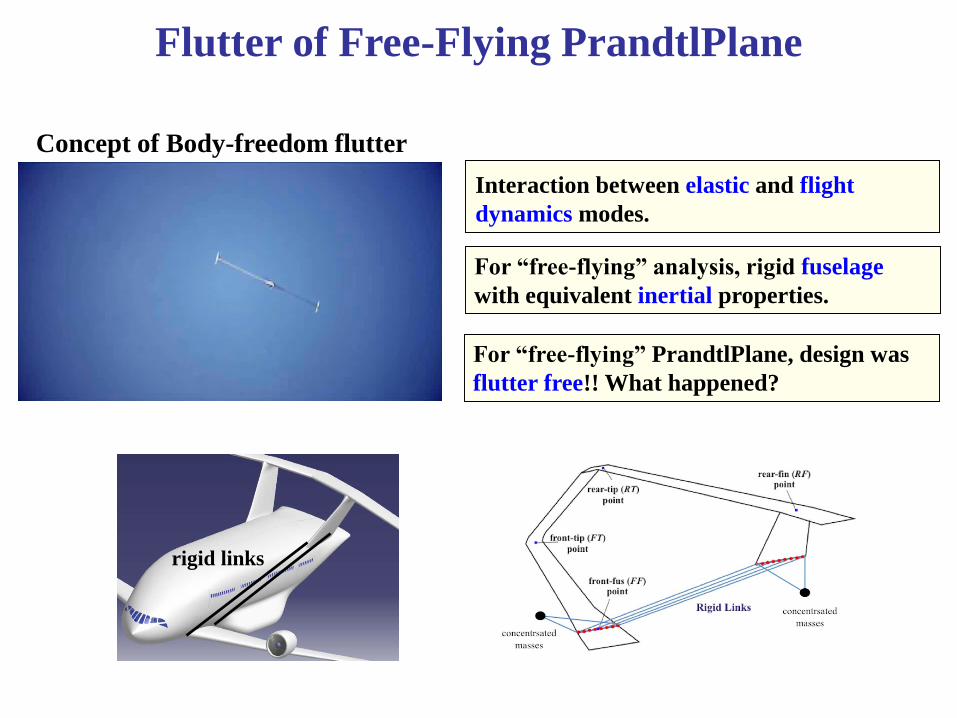
Flutter of Free-Flying PrandtlPlane
Concept of Body-freedom flutter
For “free-flying” analysis, rigid fuselage
with equivalent inertial properties.
Interaction between elastic and flight
dynamics modes.
rigid links
For “free-flying” PrandtlPlane, design was
flutter free!! What happened?
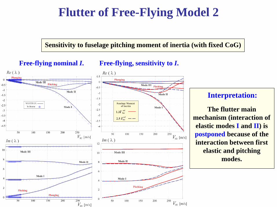
Flutter of Free-Flying Model 2
Free-flying nominal I. Free-flying, sensitivity to I.
Sensitivity to fuselage pitching moment of inertia (with fixed CoG)
Interpretation:
The flutter main
mechanism (interaction of
elastic modes I and II) is
postponed because of the
interaction between first
elastic and pitching
modes.
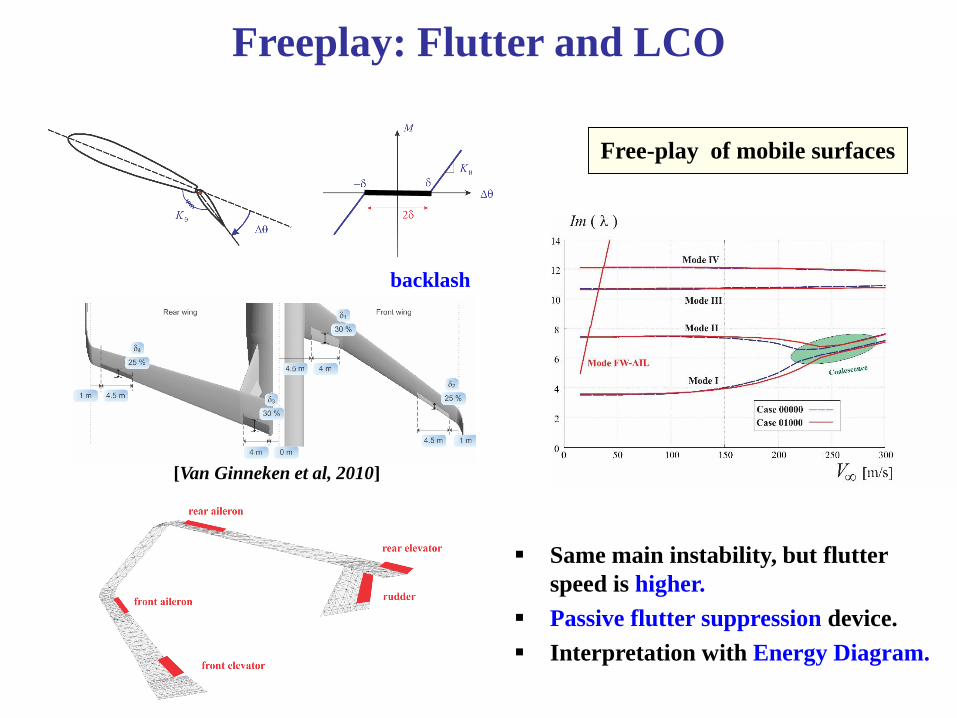
Freeplay: Flutter and LCO
Free-play of mobile surfaces
backlash
[Van Ginneken et al, 2010]
▪ Same main instability, but flutter
speed is higher.
▪ Passive flutter suppression device.
▪ Interpretation with Energy Diagram.
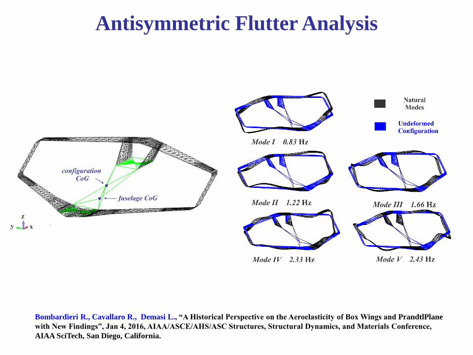
Antisymmetric Flutter Analysis
Bombardieri R., Cavallaro R., Demasi L., “A Historical Perspective on the Aeroelasticity of Box Wings and PrandtlPlane
with New Findings”, Jan 4, 2016, AIAA/ASCE/AHS/ASC Structures, Structural Dynamics, and Materials Conference,
AIAA SciTech, San Diego, California.
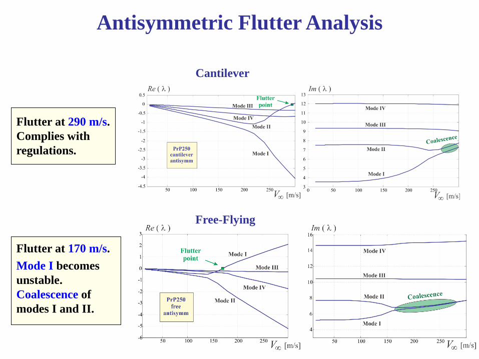
Antisymmetric Flutter Analysis
Flutter at 170 m/s.
Mode I becomes
unstable.
Coalescence of
modes I and II.
Flutter at 290 m/s.
Complies with
regulations.
Free-Flying
Cantilever
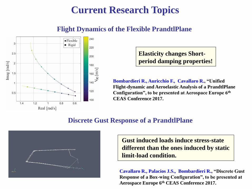
Current Research Topics
Bombardieri R., Auricchio F., Cavallaro R., “Unified
Flight-dynamic and Aeroelastic Analysis of a PrandtlPlane
Configuration”, to be presented at Aerospace Europe 6th
CEAS Conference 2017.
Elasticity changes Short-
period damping properties!
Flight Dynamics of the Flexible PrandtlPlane
Discrete Gust Response of a PrandtlPlane
Cavallaro R., Palacios J.S., Bombardieri R., “Discrete Gust
Response of a Box-wing Configuration”, to be presented at
Aerospace Europe 6th CEAS Conference 2017.
Gust induced loads induce stress-state
different than the ones induced by static
limit-load condition.
AGENDA
➢ Introduction
➢ Unconventional Aircraft Configuration: the Box
Wing/PrandtlPlane case
➢CSHELL: An Inhouse Aeroelastic Computational Tool
➢ UC3M – UoB Collaboration: Preliminary Results
➢ Conclusions
CSHELLInhouse Aeroelastic Computational Tool
WHAT IS CSHELL?
▪ It is a numerical FSI tool capable of performing several analyses,
ranging from purely structural and aerodynamic, to aeroelastic ones.
HISTORY
▪ Conceived and initially programmed by L. Demasi (SDSU - San
Diego State University)
▪ Currently under development (new submodules, e.g., Flight
Dynamics module) at UC3M and SDSU.
FLEXIBILITY
▪ Developed in Fortran/C++, Matlab. At the price of an increased
maintenance cost, Matlab allows to faster develop, validate, and
integrate new features (and not only).
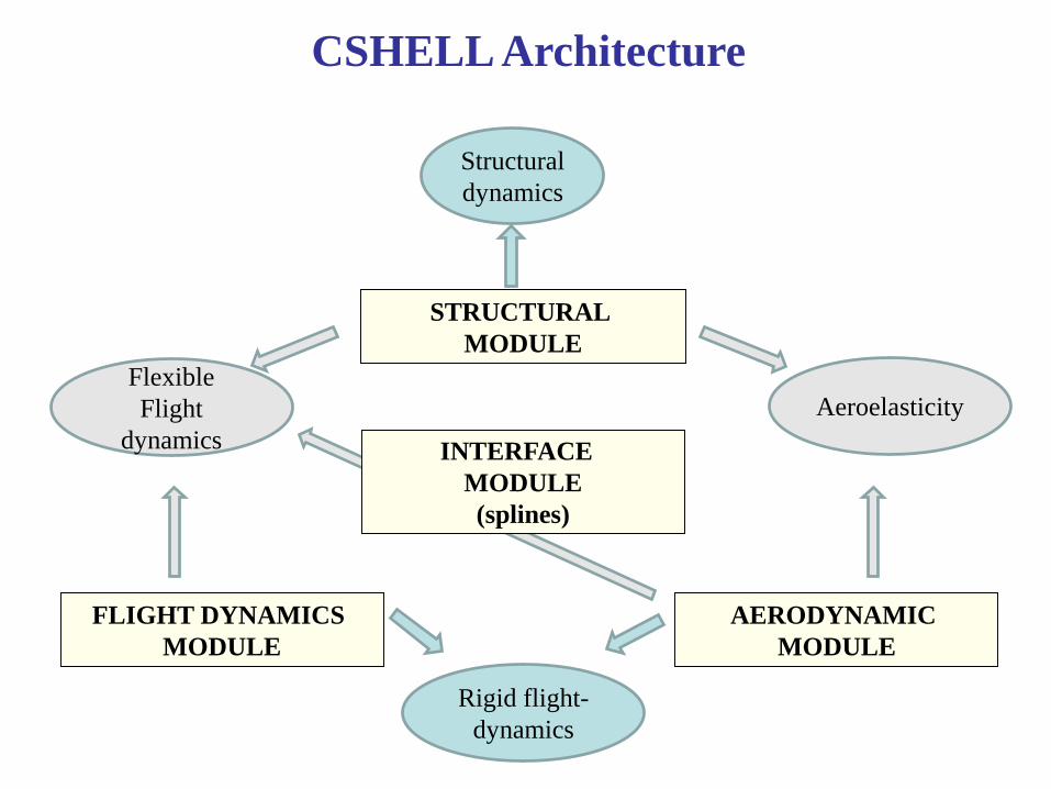
CSHELL Architecture
STRUCTURAL
MODULE
AERODYNAMIC
MODULE
INTERFACE
MODULE
(splines)
FLIGHT DYNAMICS
MODULE
Structural
dynamics
Aeroelasticity
Rigid flight-
dynamics
Flexible
Flight
dynamics
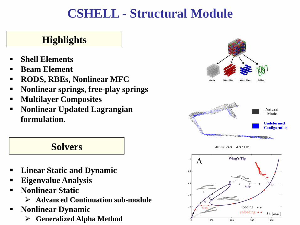
CSHELL - Structural Module
Solvers
▪ Linear Static and Dynamic
▪ Eigenvalue Analysis
▪ Nonlinear Static➢ Advanced Continuation sub-module
▪ Nonlinear Dynamic➢ Generalized Alpha Method
Highlights
▪ Shell Elements
▪ Beam Element
▪ RODS, RBEs, Nonlinear MFC
▪ Nonlinear springs, free-play springs
▪ Multilayer Composites
▪ Nonlinear Updated Lagrangian
formulation.
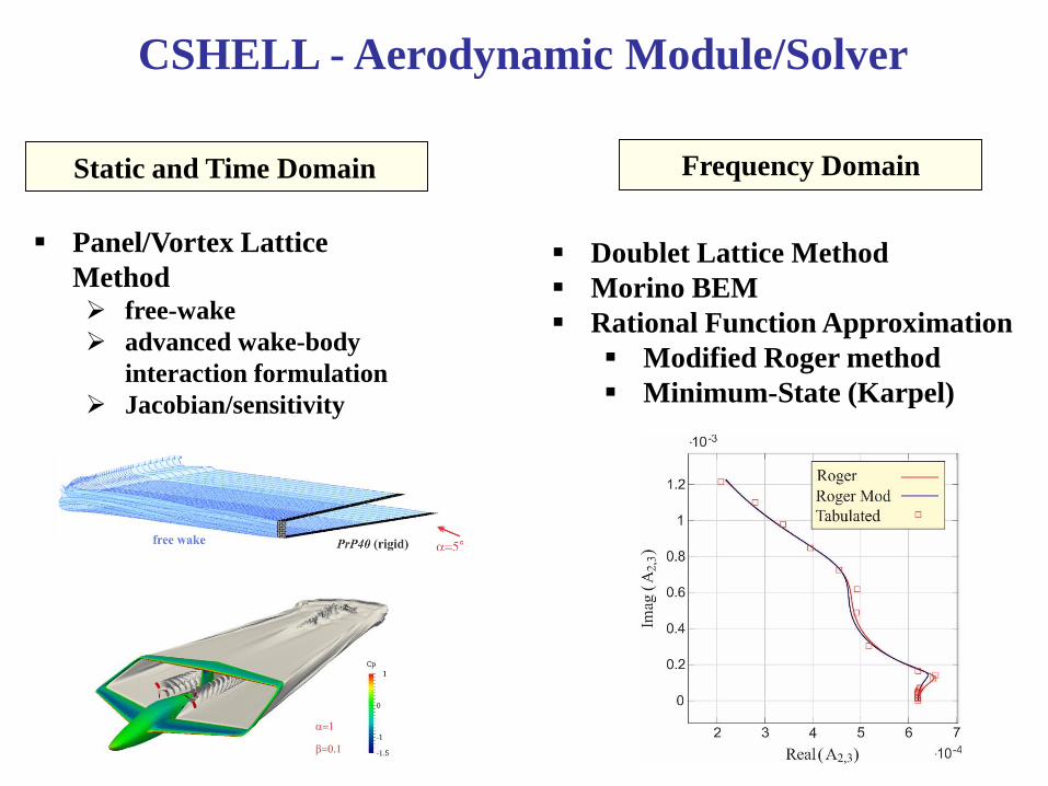
CSHELL - Aerodynamic Module/Solver
Static and Time Domain
▪ Panel/Vortex Lattice
Method➢ free-wake
➢ advanced wake-body
interaction formulation
➢ Jacobian/sensitivity
Frequency Domain
▪ Doublet Lattice Method
▪ Morino BEM
▪ Rational Function Approximation
▪ Modified Roger method
▪ Minimum-State (Karpel)
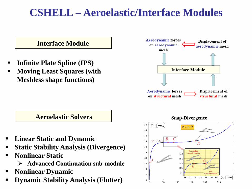
CSHELL – Aeroelastic/Interface Modules
Aeroelastic Solvers
▪ Linear Static and Dynamic
▪ Static Stability Analysis (Divergence)
▪ Nonlinear Static➢ Advanced Continuation sub-module
▪ Nonlinear Dynamic
▪ Dynamic Stability Analysis (Flutter)
Snap-Divergence
▪ Infinite Plate Spline (IPS)
▪ Moving Least Squares (with
Meshless shape functions)
Interface Module
AGENDA
➢ Introduction
➢ Unconventional Aircraft Configuration: the Box
Wing/PrandtlPlane case
➢ CSHELL: An Inhouse Aeroelastic Computational Tool
➢UC3M – UoB Collaboration: Preliminary Results
➢ Conclusions
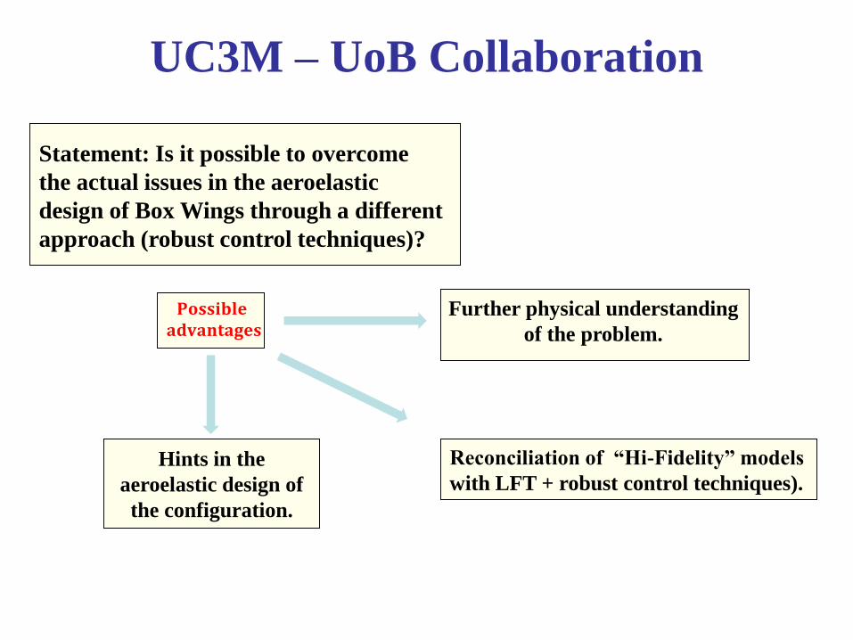
UC3M – UoB Collaboration
Statement: Is it possible to overcome
the actual issues in the aeroelastic
design of Box Wings through a different
approach (robust control techniques)?
𝐏𝐨𝐬𝐬𝐢𝐛𝐥𝐞𝐚𝐝𝐯𝐚𝐧𝐭𝐚𝐠𝐞𝐬
Further physical understanding
of the problem.
Hints in the
aeroelastic design of
the configuration.
Reconciliation of “Hi-Fidelity” models
with LFT + robust control techniques).
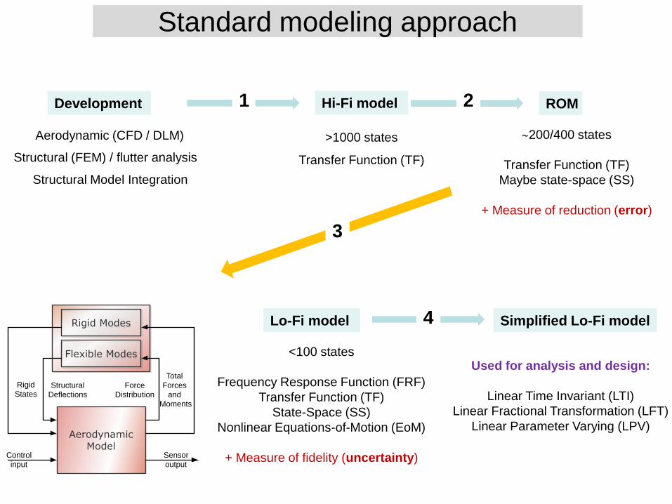
Development
Aerodynamic (CFD / DLM)
Structural (FEM) / flutter analysis
Structural Model Integration
Hi-Fi model ROM
>1000 states
Transfer Function (TF)
200/400 states
Transfer Function (TF)
Maybe state-space (SS)
+ Measure of reduction (error)
Standard modeling approach
Rigid Modes
Flexible Modes
Aerodynamic Model
Total
Forces
and
Moments
Force
Distribution
Rigid
StatesStructural
Deflections
Control
input
Sensor
output
Lo-Fi model
<100 states
Frequency Response Function (FRF)
Transfer Function (TF)
State-Space (SS)
Nonlinear Equations-of-Motion (EoM)
+ Measure of fidelity (uncertainty)
Simplified Lo-Fi model
Used for analysis and design:
Linear Time Invariant (LTI)
Linear Fractional Transformation (LFT)
Linear Parameter Varying (LPV)
1 2
3
4
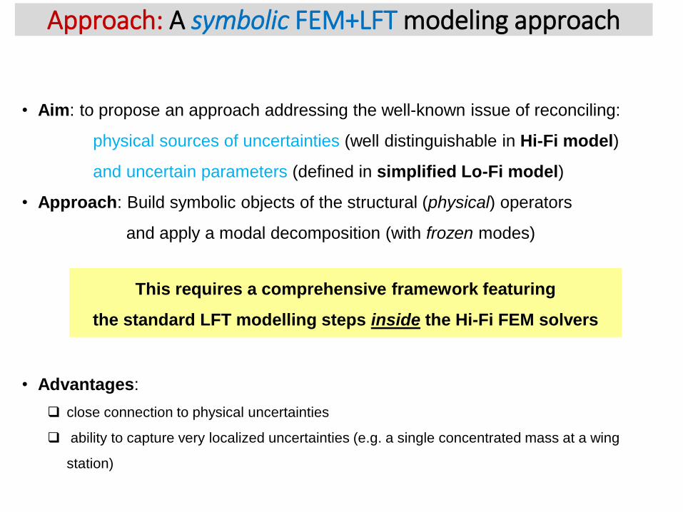
• Aim: to propose an approach addressing the well-known issue of reconciling:
physical sources of uncertainties (well distinguishable in Hi-Fi model)
and uncertain parameters (defined in simplified Lo-Fi model)
• Approach: Build symbolic objects of the structural (physical) operators
and apply a modal decomposition (with frozen modes)
This requires a comprehensive framework featuring
the standard LFT modelling steps inside the Hi-Fi FEM solvers
• Advantages:
close connection to physical uncertainties
ability to capture very localized uncertainties (e.g. a single concentrated mass at a wing
station)
Approach: A symbolic FEM+LFT modeling approach
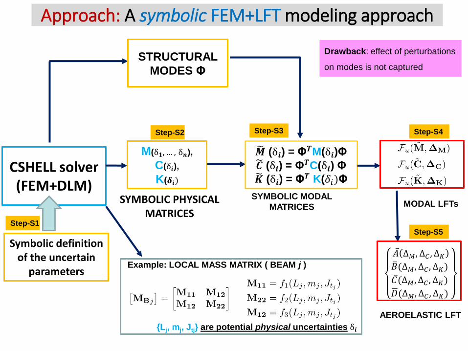
CSHELL solver(FEM+DLM)
Example: LOCAL MASS MATRIX ( BEAM j )
{Lj, mj, Jtj} are potential physical uncertainties δ𝒊
Symbolic definition of the uncertain
parameters
Step-S1
M(δ𝟏, … , δ𝒏),
C(δ𝒊),
K(𝜹𝒊)
STRUCTURAL
MODES Φ
SYMBOLIC PHYSICAL MATRICES
Step-S2
෩𝑴 (δ𝒊) = Φ𝑻M(δ𝒊)Φ෩𝑪 (δ𝒊) = Φ𝑻C(δ𝒊) Φ෩𝑲 (δ𝒊) = Φ𝑻 K(𝛿𝑖)Φ
SYMBOLIC MODAL
MATRICES
Step-S3
MODAL LFTs
AEROELASTIC LFT
Step-S4
ҧ𝐴 ∆𝑀 , ∆𝐶 , ∆𝐾ത𝐵(∆𝑀, ∆𝐶 , ∆𝐾)ҧ𝐶(∆𝑀 , ∆𝐶 , ∆𝐾)ഥ𝐷(∆𝑀, ∆𝐶 , ∆𝐾)
Step-S5
Drawback: effect of perturbations
on modes is not captured
Approach: A symbolic FEM+LFT modeling approach
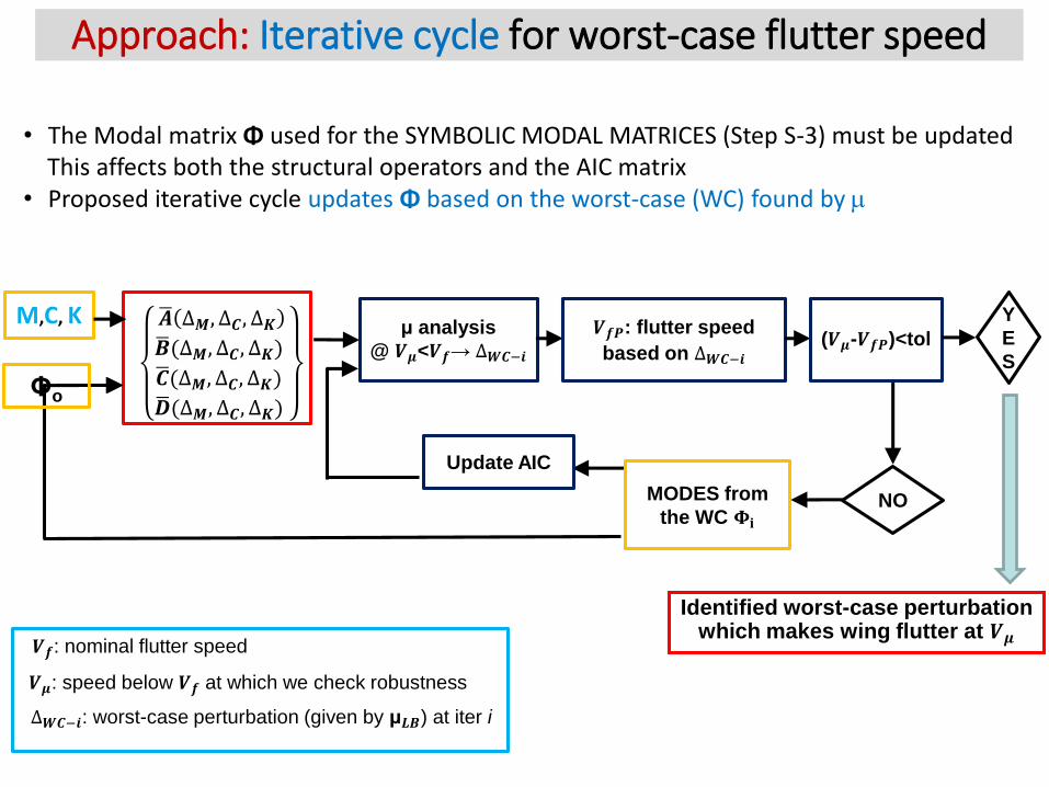
Approach: Iterative cycle for worst-case flutter speed
• The Modal matrix Φ used for the SYMBOLIC MODAL MATRICES (Step S-3) must be updatedThis affects both the structural operators and the AIC matrix
• Proposed iterative cycle updates Φ based on the worst-case (WC) found by m
NO
Update AIC
MODES from
the WC 𝚽𝐢
𝑽𝝁: speed below 𝑽𝒇 at which we check robustness
𝑽𝒇: nominal flutter speed
∆𝑾𝑪−𝒊: worst-case perturbation (given by μ𝑳𝑩) at iter i
μ analysis
@ 𝑽𝝁<𝑽𝒇→ ∆𝑾𝑪−𝒊
𝑽𝒇𝑷: flutter speed
based on ∆𝑾𝑪−𝒊
(𝑽𝝁-𝑽𝒇𝑷)<tolM,C, K ഥ𝑨 ∆𝑴, ∆𝑪, ∆𝑲
ഥ𝑩(∆𝑴, ∆𝑪, ∆𝑲)ഥ𝑪(∆𝑴, ∆𝑪, ∆𝑲)ഥ𝑫(∆𝑴, ∆𝑪, ∆𝑲)
Identified worst-case perturbation which makes wing flutter at 𝑽𝝁
Y
E
S
Φo
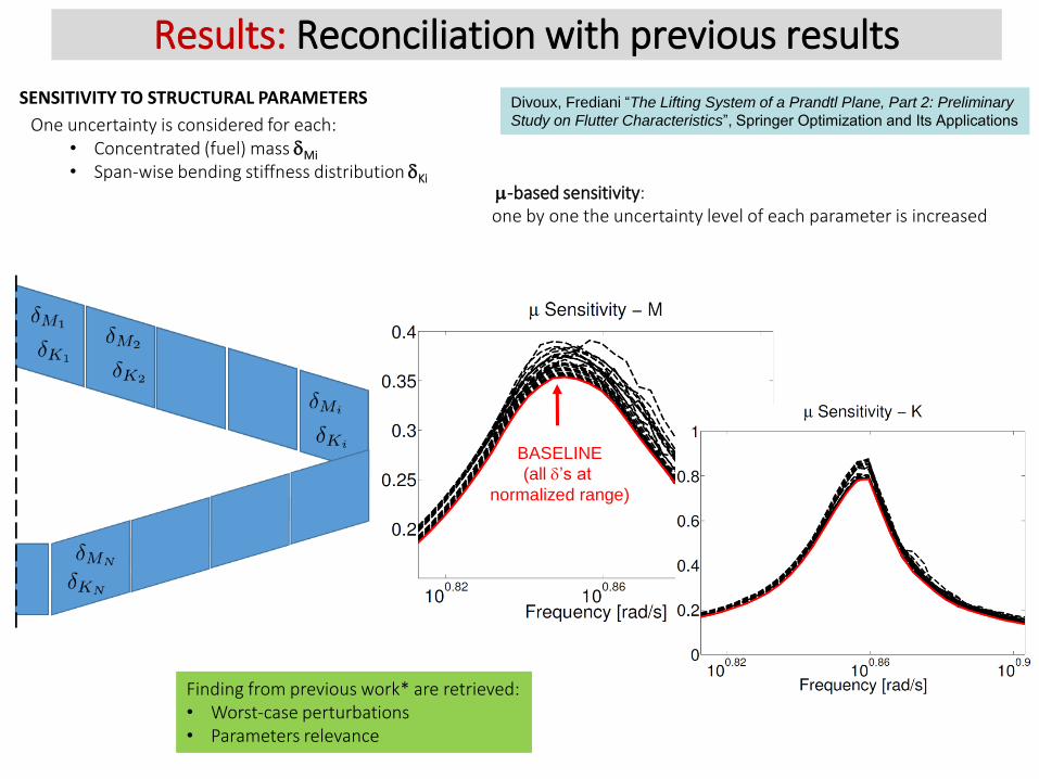
Results: Reconciliation with previous results
One uncertainty is considered for each: • Concentrated (fuel) mass Mi
• Span-wise bending stiffness distribution Ki
BASELINE
(all ’s at
normalized range)
m-based sensitivity: one by one the uncertainty level of each parameter is increased
Divoux, Frediani “The Lifting System of a Prandtl Plane, Part 2: Preliminary
Study on Flutter Characteristics”, Springer Optimization and Its Applications
Finding from previous work* are retrieved:• Worst-case perturbations• Parameters relevance
SENSITIVITY TO STRUCTURAL PARAMETERS
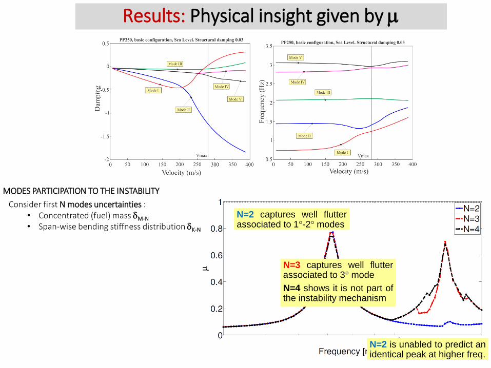
Results: Physical insight given by m
MODES PARTICIPATION TO THE INSTABILITY
Consider first N modes uncertainties : • Concentrated (fuel) mass M-N
• Span-wise bending stiffness distribution K-N
N=2 captures well flutterassociated to 1°-2° modes
N=2 is unabled to predict anidentical peak at higher freq.
N=3 captures well flutterassociated to 3° mode
N=4 shows it is not part ofthe instability mechanism
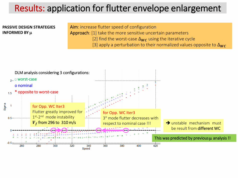
Results: application for flutter envelope enlargement
PASSIVE DESIGN STRATEGIES INFORMED BY m
1𝒔𝒕-𝟐𝒏𝒅 MODE INSTABILITY
𝟑𝒓𝒅 MODE INSTABILITY
DLM analysis considering 3 configurations:
worst-case
o nominal
* opposite to worst-case
Aim: increase flutter speed of configurationApproach: [1] take the more sensitive uncertain parameters
[2] find the worst-case ∆𝑾𝑪 using the iterative cycle[3] apply a perturbation to their normalized values opposite to ∆𝑾𝑪
This was predicted by previous m analysis !!
for Opp. WC Iter3Flutter greatly improved for1st-2nd mode instability𝑽𝒇 from 296 to 310 m/s
for Opp. WC Iter33° mode flutter decreases withrespect to nominal case !!! unstable mechanism must
be result from different WC
AGENDA
➢ Introduction
➢ Unconventional Aircraft Configuration: the Box
Wing/PrandtlPlane case
➢ CSHELL: An Inhouse Aeroelastic Computational Tool
➢ UC3M – UoB Collaboration: Preliminary Results
➢Conclusions
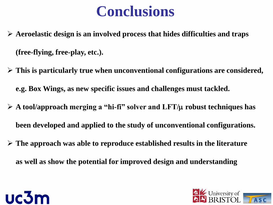
Conclusions
➢ Aeroelastic design is an involved process that hides difficulties and traps
(free-flying, free-play, etc.).
➢ This is particularly true when unconventional configurations are considered,
e.g. Box Wings, as new specific issues and challenges must tackled.
➢ A tool/approach merging a “hi-fi” solver and LFT/m robust techniques has
been developed and applied to the study of unconventional configurations.
➢ The approach was able to reproduce established results in the literature
as well as show the potential for improved design and understanding
A novel approach to aeroelastic
design of unconventional
configurationsMerging FSI solvers and LFT/μ tools
Rauno Cavallaro, Rocco Bombardieri.
Andres Marcos, Andrea Iannelli.