HEAVY DUTY STOPPER CYLINDER · · 2018-02-23HEAVY DUTY STOPPER CYLINDER . ... Check items . 6-2....
25
Doc. no. RS2H-OM0012P- B PRODUCT NAME HEAVY DUTY STOPPER CYLINDER MODEL / Series / Product Number RS2H Series (φ50 to φ80)
Transcript of HEAVY DUTY STOPPER CYLINDER · · 2018-02-23HEAVY DUTY STOPPER CYLINDER . ... Check items . 6-2....
Doc. no. RS2H-OM0012P- B
PRODUCT NAME
HEAVY DUTY STOPPER CYLINDER
MODEL / Series / Product Number
RS2H Series (φ50 to φ80)
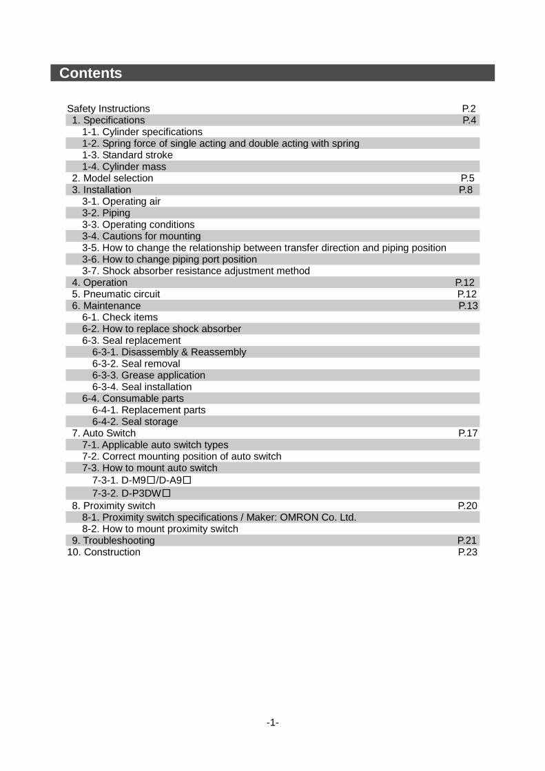
Contents
Safety Instructions P.2 1. Specifications P.4
1-1. Cylinder specifications 1-2. Spring force of single acting and double acting with spring 1-3. Standard stroke 1-4. Cylinder mass
2. Model selection P.5 3. Installation P.8
3-1. Operating air 3-2. Piping 3-3. Operating conditions 3-4. Cautions for mounting 3-5. How to change the relationship between transfer direction and piping position 3-6. How to change piping port position 3-7. Shock absorber resistance adjustment method
4. Operation P.12 5. Pneumatic circuit P.12 6. Maintenance P.13
6-1. Check items 6-2. How to replace shock absorber 6-3. Seal replacement
6-3-1. Disassembly & Reassembly 6-3-2. Seal removal 6-3-3. Grease application 6-3-4. Seal installation
6-4. Consumable parts 6-4-1. Replacement parts 6-4-2. Seal storage
7. Auto Switch P.17 7-1. Applicable auto switch types 7-2. Correct mounting position of auto switch 7-3. How to mount auto switch 7-3-1. D-M9□/D-A9□
7-3-2. D-P3DW□ 8. Proximity switch P.20
8-1. Proximity switch specifications / Maker: OMRON Co. Ltd. 8-2. How to mount proximity switch
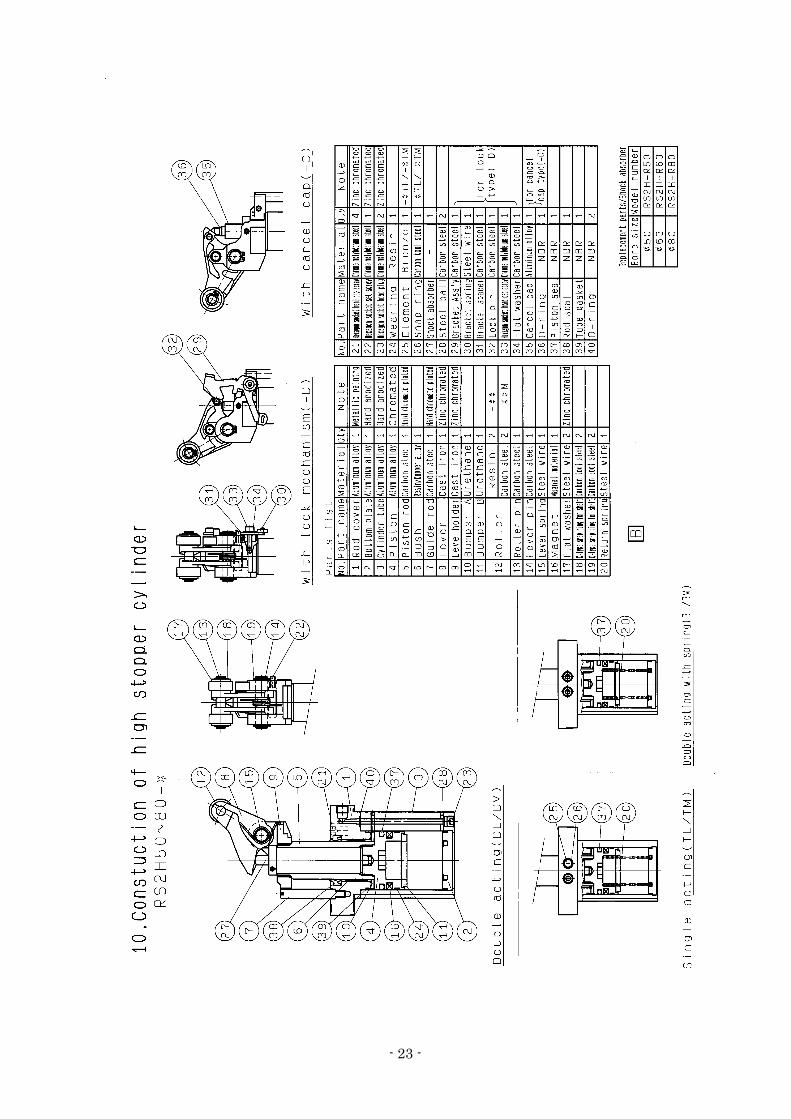
9. Troubleshooting P.21 10. Construction P.23
-1-
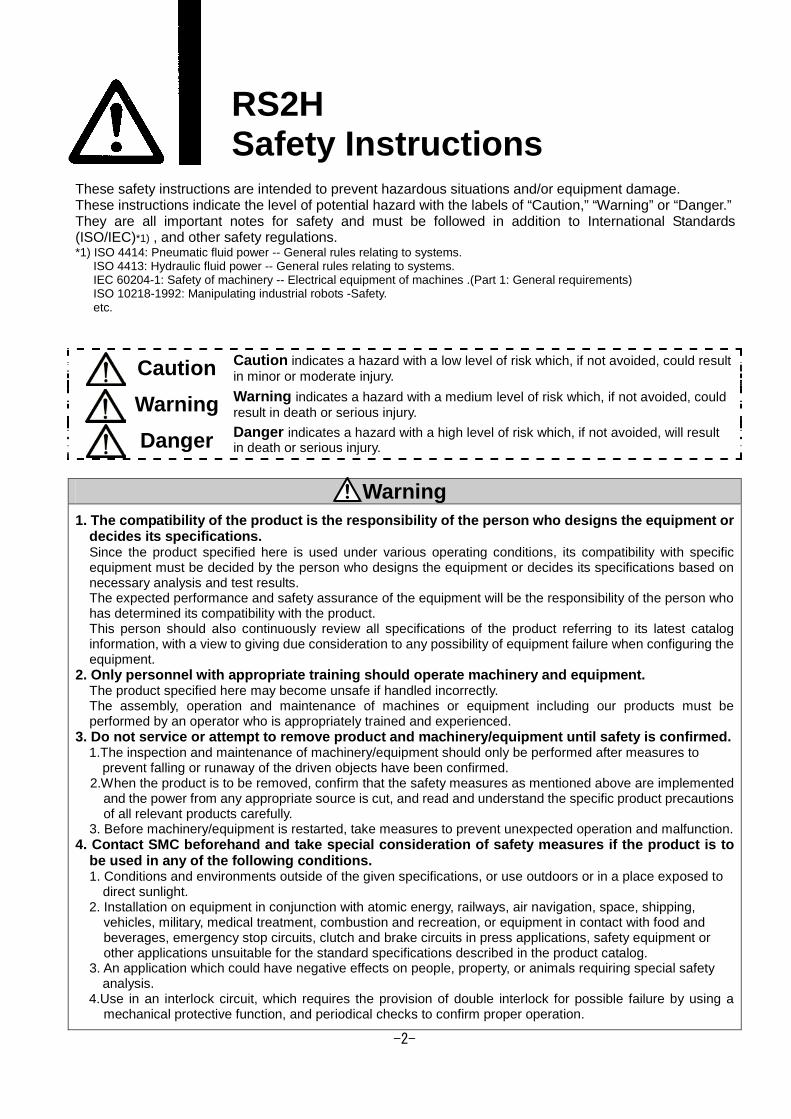
RS2H Safety Instructions These safety instructions are intended to prevent hazardous situations and/or equipment damage. These instructions indicate the level of potential hazard with the labels of “Caution,” “Warning” or “Danger.” They are all important notes for safety and must be followed in addition to International Standards (ISO/IEC)*1) , and other safety regulations. *1) ISO 4414: Pneumatic fluid power -- General rules relating to systems. ISO 4413: Hydraulic fluid power -- General rules relating to systems. IEC 60204-1: Safety of machinery -- Electrical equipment of machines .(Part 1: General requirements) ISO 10218-1992: Manipulating industrial robots -Safety. etc.
Caution Caution indicates a hazard with a low level of risk which, if not avoided, could result in minor or moderate injury.
Warning Warning indicates a hazard with a medium level of risk which, if not avoided, could result in death or serious injury.
Danger Danger indicates a hazard with a high level of risk which, if not avoided, will result in death or serious injury.
Warning 1. The compatibility of the product is the responsibility of the person who designs the equipment or
decides its specifications. Since the product specified here is used under various operating conditions, its compatibility with specific equipment must be decided by the person who designs the equipment or decides its specifications based on necessary analysis and test results. The expected performance and safety assurance of the equipment will be the responsibility of the person who has determined its compatibility with the product. This person should also continuously review all specifications of the product referring to its latest catalog information, with a view to giving due consideration to any possibility of equipment failure when configuring the equipment.
2. Only personnel with appropriate training should operate machinery and equipment. The product specified here may become unsafe if handled incorrectly. The assembly, operation and maintenance of machines or equipment including our products must be performed by an operator who is appropriately trained and experienced.
3. Do not service or attempt to remove product and machinery/equipment until safety is confirmed. 1.The inspection and maintenance of machinery/equipment should only be performed after measures to
prevent falling or runaway of the driven objects have been confirmed. 2.When the product is to be removed, confirm that the safety measures as mentioned above are implemented and the power from any appropriate source is cut, and read and understand the specific product precautions of all relevant products carefully. 3. Before machinery/equipment is restarted, take measures to prevent unexpected operation and malfunction.
4. Contact SMC beforehand and take special consideration of safety measures if the product is to be used in any of the following conditions. 1. Conditions and environments outside of the given specifications, or use outdoors or in a place exposed to direct sunlight. 2. Installation on equipment in conjunction with atomic energy, railways, air navigation, space, shipping,
vehicles, military, medical treatment, combustion and recreation, or equipment in contact with food and beverages, emergency stop circuits, clutch and brake circuits in press applications, safety equipment or other applications unsuitable for the standard specifications described in the product catalog.
3. An application which could have negative effects on people, property, or animals requiring special safety analysis.
4.Use in an interlock circuit, which requires the provision of double interlock for possible failure by using a mechanical protective function, and periodical checks to confirm proper operation.
-2-
RS2H Safety Instructions
Caution 1.The product is provided for use in manufacturing industries.
The product herein described is basically provided for peaceful use in manufacturing industries. If considering using the product in other industries, consult SMC beforehand and exchange specifications or a contract if necessary. If anything is unclear, contact your nearest sales branch.
Limited warranty and Disclaimer/Compliance Requirements The product used is subject to the following “Limited warranty and Disclaimer” and “Compliance Requirements”. Read and accept them before using the product.
Limited warranty and Disclaimer 1.The warranty period of the product is 1 year in service or 1.5 years after the product
isdelivered.∗2) Also, the product may have specified durability, running distance or replacement parts. Please consult your nearest sales branch.
2. For any failure or damage reported within the warranty period which is clearly our responsibility, a replacement product or necessary parts will be provided. This limited warranty applies only to our product independently, and not to any other damage
incurred due to the failure of the product. 3. Prior to using SMC products, please read and understand the warranty terms and disclaimers
noted in the specified catalog for the particular products.
∗2) Vacuum pads are excluded from this 1 year warranty. A vacuum pad is a consumable part, so it is warranted for a year after it is delivered.
Also, even within the warranty period, the wear of a product due to the use of the vacuum pad or failure due to the deterioration of rubber material are not covered by the limited
warranty.
Compliance Requirements 1. The use of SMC products with production equipment for the manufacture of weapons of mass
destruction(WMD) or any other weapon is strictly prohibited. 2. The exports of SMC products or technology from one country to another are govemed by the
relevant security laws and regulation of the countries involved in the transaction. Prior to the shipment of a SMC product to another country, assure that all local rules goveming that export are known and followed.
The product is provided for use in manufacturing industries. The product herein described is basically provided for peaceful use in manufacturing industries. If considering using the product in other industries, consult SMC beforehand and exchange specifications or a contract if necessary. 契約などを行ってください。
The product is provided for use in manufacturing industries. The product herein described is basically provided for peaceful use in manufacturing industries. If considering using the product in other industries, consult SMC beforehand and exchange specifications or a contract if necessary. 契約などを行ってください。
-3-
- 4 -
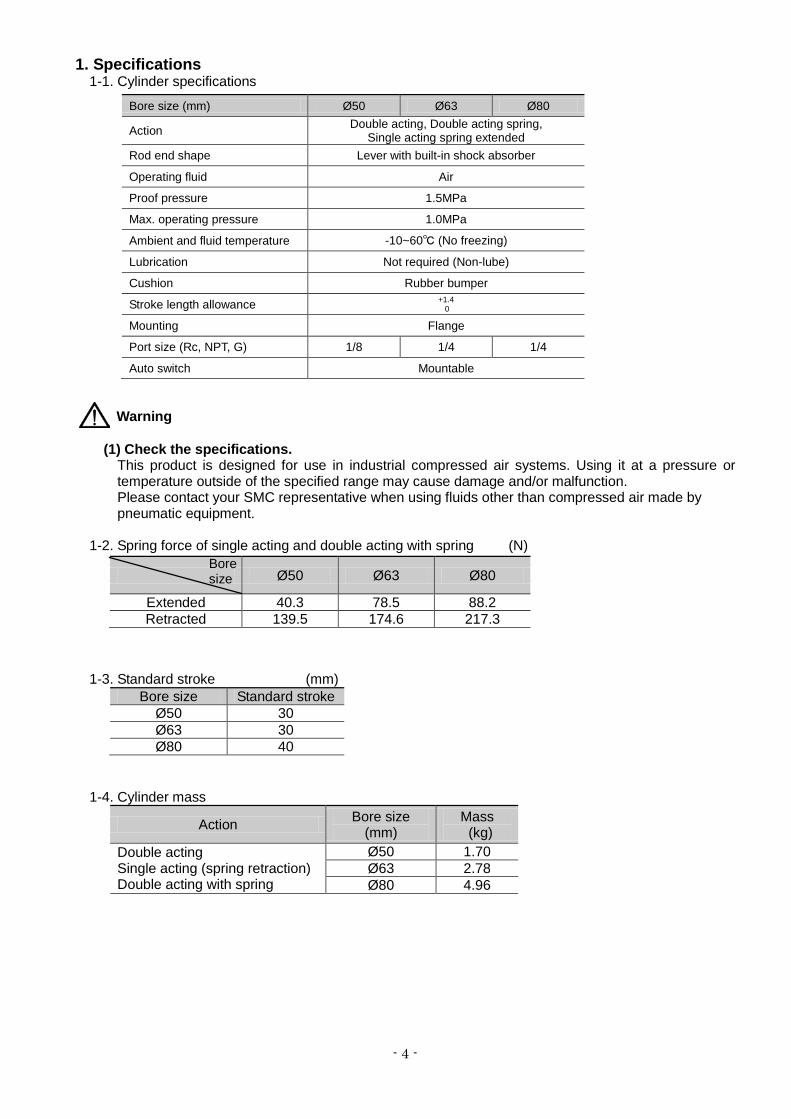
1. Specifications 1-1. Cylinder specifications
Warning (1) Check the specifications.
This product is designed for use in industrial compressed air systems. Using it at a pressure or temperature outside of the specified range may cause damage and/or malfunction. Please contact your SMC representative when using fluids other than compressed air made by pneumatic equipment.
1-2. Spring force of single acting and double acting with spring (N) 1-3. Standard stroke (mm)
Bore size Standard stroke Ø50 30 Ø63 30 Ø80 40
1-4. Cylinder mass
Action Bore size (mm)
Mass (kg)
Double acting Single acting (spring retraction) Double acting with spring
Ø50 1.70 Ø63 2.78 Ø80 4.96
Bore size (mm) Ø50 Ø63 Ø80
Action Double acting, Double acting spring, Single acting spring extended
Rod end shape Lever with built-in shock absorber
Operating fluid Air
Proof pressure 1.5MPa
Max. operating pressure 1.0MPa
Ambient and fluid temperature -10~60℃ (No freezing)
Lubrication Not required (Non-lube)
Cushion Rubber bumper
Stroke length allowance +1.4 0
Mounting Flange
Port size (Rc, NPT, G) 1/8 1/4 1/4
Auto switch Mountable
Ø50 Ø63 Ø80
Extended 40.3 78.5 88.2 Retracted 139.5 174.6 217.3
Bore size
- 5 -
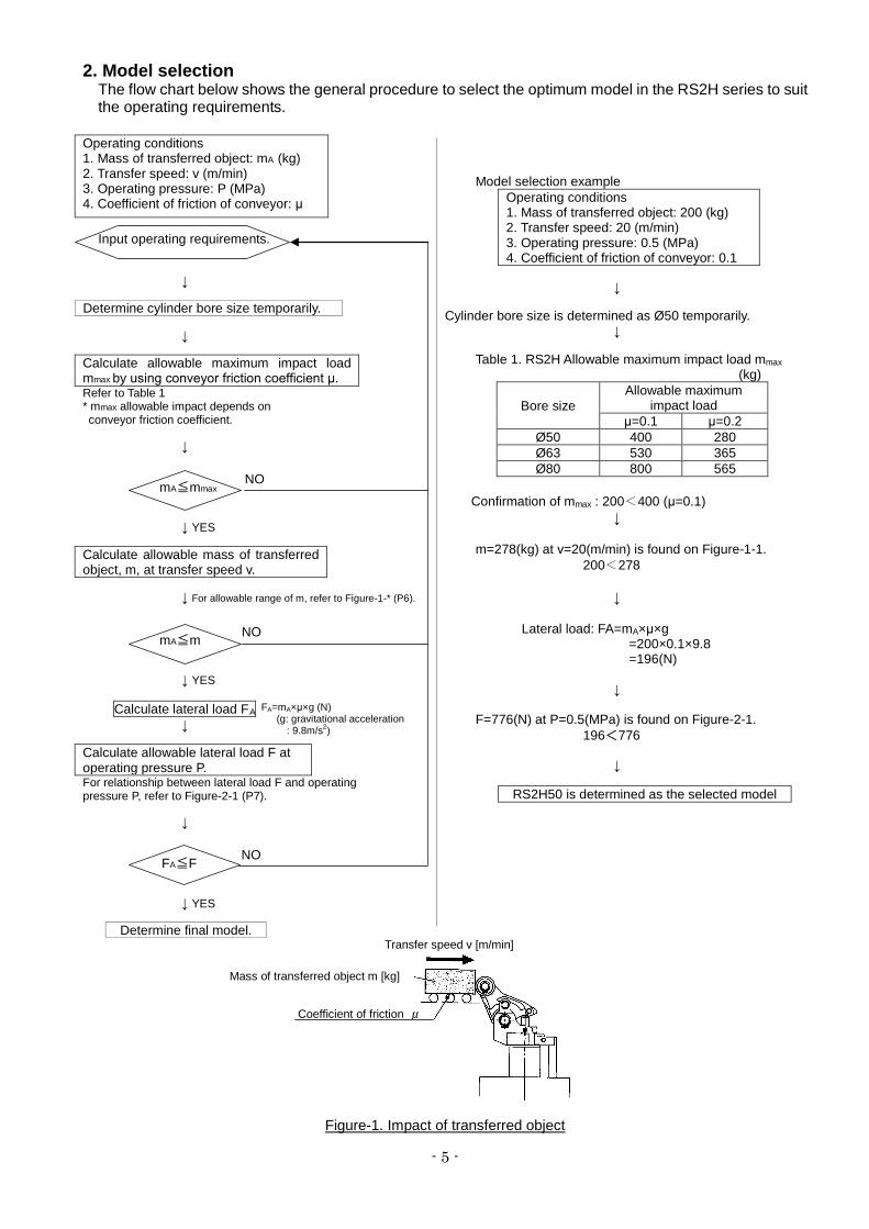
2. Model selection The flow chart below shows the general procedure to select the optimum model in the RS2H series to suit the operating requirements.
Operating conditions 1. Mass of transferred object: mA 2. Transfer speed: v (m/min)
(kg)
3. Operating pressure: P (MPa) 4. Coefficient of friction of conveyor: μ
Input operating requirements.
↓ Determine cylinder bore size temporarily.
↓ Calculate allowable maximum impact load mmax by using conveyor friction coefficient μ. Refer to Table 1 * mmax allowable impact depends on conveyor friction coefficient.
↓
mA≦mmax
↓ YES Calculate allowable mass of transferred object, m, at transfer speed v.
↓ For allowable range of m, refer to Figure-1-* (P6).
mA≦m
↓ YES
Calculate lateral load F↓
A
Calculate allowable lateral load F at operating pressure P. For relationship between lateral load F and operating pressure P, refer to Figure-2-1 (P7).
↓
FA≦F
↓ YES
Determine final model.
Figure-1. Impact of transferred object
Model selection example Operating conditions 1. Mass of transferred object: 200 (kg) 2. Transfer speed: 20 (m/min) 3. Operating pressure: 0.5 (MPa) 4. Coefficient of friction of conveyor: 0.1
↓
Cylinder bore size is determined as Ø50 temporarily.
↓
Table 1. RS2H Allowable maximum impact load mmax (kg)
Bore size Allowable maximum
impact load μ=0.1 μ=0.2
Ø50 400 280 Ø63 530 365 Ø80 800 565
Confirmation of mmax : 200<400 (μ=0.1)
↓
m=278(kg) at v=20(m/min) is found on Figure-1-1. 200<278
↓
Lateral load: FA=mA×μ×g
=200×0.1×9.8 =196(N)
↓
F=776(N) at P=0.5(MPa) is found on Figure-2-1.
196<776
↓
RS2H50 is determined as the selected model
NO
NO
NO
Mass of transferred object m [kg]
Coefficient of friction μ
Transfer speed v [m/min]
FA=mA×μ×g (N) (g: gravitational acceleration : 9.8m/s2)
- 6 -
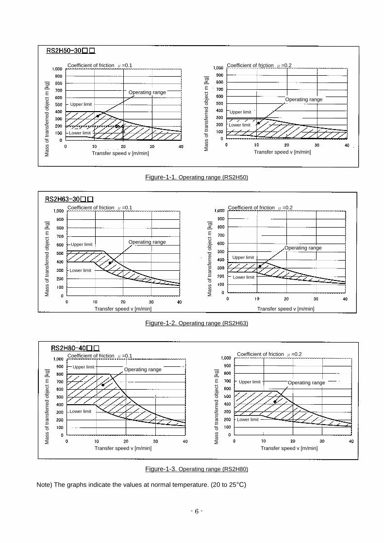
Figure-1-1. Operating range (RS2H50)
Figure-1-2. Operating range (RS2H63)
Figure-1-3. Operating range (RS2H80)
Note) The graphs indicate the values at normal temperature. (20 to 25°C)
Transfer speed v [m/min] Transfer speed v [m/min] Mas
s of
tran
sfer
red
obje
ct m
[kg]
Mas
s of
tran
sfer
red
obje
ct m
[kg]
Coefficient of friction μ=0.1 Coefficient of friction μ=0.2
Operating range Operating range
Lower limit
Lower limit
Upper limit
Upper limit
Mas
s of
tran
sfer
red
obje
ct m
[kg]
Mas
s of
tran
sfer
red
obje
ct m
[kg]
Transfer speed v [m/min] Transfer speed v [m/min]
Coefficient of friction μ=0.1 Coefficient of friction μ=0.2
Operating range Operating range
Upper limit
Lower limit
Upper limit
Lower limit
Coefficient of friction μ=0.1 Coefficient of friction μ=0.2
Operating range
Operating range
Mas
s of
tran
sfer
red
obje
ct m
[kg]
Transfer speed v [m/min]
Mas
s of
tran
sfer
red
obje
ct m
[kg]
Transfer speed v [m/min]
Upper limit
Upper limit
Lower limit
Lower limit

- 7 -
Warning
(1) Precautions for model selection The compatibility of the product is the responsibility of the person who designs the pneumatic equipment or decides its specifications.
(2) Use within the specified range
If the condition exceeds the specified operating range, it will cause excessive impact or vibration to the stopper cylinder, leading to possible damages.
(3) There is a possibility of dangerous sudden action by air cylinders if sliding parts of
machinery are twisted due to external forces, etc. In such cases, human injury may occur; e.g., by catching hands or feet in the machinery, or damage to the machinery itself may occur. Therefore, the machine should be designed to avoid such dangers.
(4) A protective cover is recommended to minimize the risk of personal injury.
If a stationary object and moving parts of a cylinder are in close proximity, personal injury may occur. Design the structure to avoid contact with the human body.
(5) Securely tighten all stationary parts and connected parts so that they will not become loose.
When a cylinder operates with high frequency or a cylinder is installed where there is a lot of vibration, ensure that all parts remain secure.
(6) Consider a possible loss of power source. Measures should be taken to protect against human injury and equipment damage in the event that there is a loss of power to equipment controlled by air pressure, electricity or hydraulics, etc.
(7) Consider emergency stops.
Design so that human injury and/or damage to machinery and equipment will not be caused when machinery is stopped by a safety device under abnormal conditions, a power outage or a manual emergency stop.
(8) Consider the action when operation is restarted after an emergency stop or abnormal stop.
Design the machinery so that human injury or equipment damage will not occur upon restart of operation. When the cylinder has to be reset at the starting position, install manual safety equipment.
(9) When a cylinder is used in a clamping, suspending and lifting mechanism There is a danger of work pieces dropping if there is a decrease of thrust due to a drop in circuit
pressure caused by a power outage, etc. Therefore, safety equipment should be installed to prevent damage to machinery and/or human injury.
Figure-2-1. Lateral load and operating pressure
Figure-2-2. Cylinder extended
Mass of transferred object m[kg]
Coefficient of friction μ
P: Cylinder operating pressure [MPa]
Lateral load F=mgμ[N] (g: gravitational acceleration=9.8[m/s2]
Lateral load: F [N]
Ope
ratin
g pr
essu
re: P
[MP
a]
- 8 -
Caution
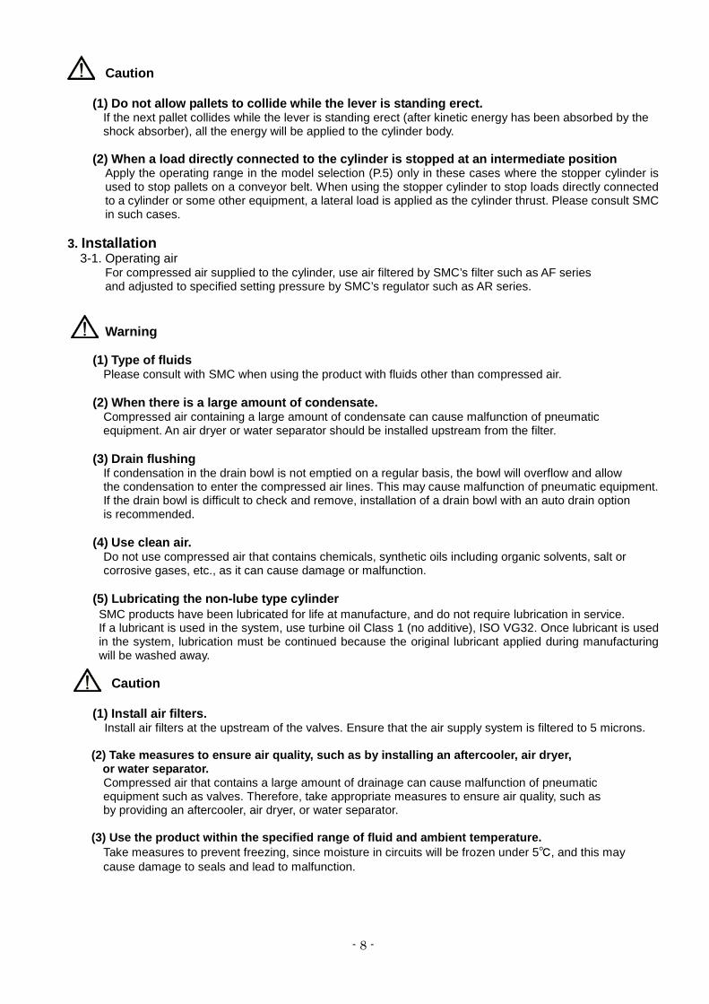
(1) Do not allow pallets to collide while the lever is standing erect. If the next pallet collides while the lever is standing erect (after kinetic energy has been absorbed by the shock absorber), all the energy will be applied to the cylinder body.
(2) When a load directly connected to the cylinder is stopped at an intermediate position
Apply the operating range in the model selection (P.5) only in these cases where the stopper cylinder is used to stop pallets on a conveyor belt. When using the stopper cylinder to stop loads directly connected to a cylinder or some other equipment, a lateral load is applied as the cylinder thrust. Please consult SMC in such cases.
3. Installation
3-1. Operating air For compressed air supplied to the cylinder, use air filtered by SMC’s filter such as AF series and adjusted to specified setting pressure by SMC’s regulator such as AR series.
Warning (1) Type of fluids Please consult with SMC when using the product with fluids other than compressed air. (2) When there is a large amount of condensate. Compressed air containing a large amount of condensate can cause malfunction of pneumatic
equipment. An air dryer or water separator should be installed upstream from the filter. (3) Drain flushing If condensation in the drain bowl is not emptied on a regular basis, the bowl will overflow and allow the condensation to enter the compressed air lines. This may cause malfunction of pneumatic equipment. If the drain bowl is difficult to check and remove, installation of a drain bowl with an auto drain option is recommended. (4) Use clean air. Do not use compressed air that contains chemicals, synthetic oils including organic solvents, salt or corrosive gases, etc., as it can cause damage or malfunction. (5) Lubricating the non-lube type cylinder
SMC products have been lubricated for life at manufacture, and do not require lubrication in service. If a lubricant is used in the system, use turbine oil Class 1 (no additive), ISO VG32. Once lubricant is used in the system, lubrication must be continued because the original lubricant applied during manufacturing will be washed away.
Caution
(1) Install air filters. Install air filters at the upstream of the valves. Ensure that the air supply system is filtered to 5 microns.
(2) Take measures to ensure air quality, such as by installing an aftercooler, air dryer, or water separator.
Compressed air that contains a large amount of drainage can cause malfunction of pneumatic equipment such as valves. Therefore, take appropriate measures to ensure air quality, such as by providing an aftercooler, air dryer, or water separator.
(3) Use the product within the specified range of fluid and ambient temperature.
Take measures to prevent freezing, since moisture in circuits will be frozen under 5℃, and this may cause damage to seals and lead to malfunction.
- 9 -
3-2. Piping
Caution
(1) Preparation before piping. Before piping is connected, it should be thoroughly blown out with air (flushing) or washed to remove cutting chips, cutting oil and other debris from inside the pipe.
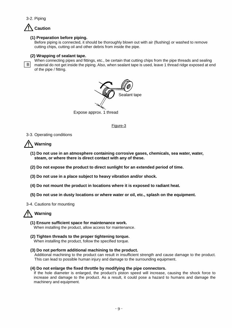
(2) Wrapping of sealant tape.
When connecting pipes and fittings, etc., be certain that cutting chips from the pipe threads and sealing material do not get inside the piping. Also, when sealant tape is used, leave 1 thread ridge exposed at end of the pipe / fitting.
Figure-3
3-3. Operating conditions Warning
(1) Do not use in an atmosphere containing corrosive gases, chemicals, sea water, water, steam, or where there is direct contact with any of these.
(2) Do not expose the product to direct sunlight for an extended period of time. (3) Do not use in a place subject to heavy vibration and/or shock. (4) Do not mount the product in locations where it is exposed to radiant heat. (5) Do not use in dusty locations or where water or oil, etc., splash on the equipment.
3-4. Cautions for mounting
Warning (1) Ensure sufficient space for maintenance work. When installing the product, allow access for maintenance. (2) Tighten threads to the proper tightening torque. When installing the product, follow the specified torque. (3) Do not perform additional machining to the product.
Additional machining to the product can result in insufficient strength and cause damage to the product. This can lead to possible human injury and damage to the surrounding equipment.
(4) Do not enlarge the fixed throttle by modifying the pipe connectors. If the hole diameter is enlarged, the product’s piston speed will increase, causing the shock force to
increase and damage to the product. As a result, it could pose a hazard to humans and damage the machinery and equipment.
Sealant tape
Expose approx. 1 thread
B
- 10 -
Caution
(1) Do not apply rotational torque to the cylinder piston rod. Align the cylinder so that it is parallel to the working face of the pallet in order to prevent rotational torque acting on the cylinder piston rod.
(2) Do not scratch or gouge the sliding part of the piston rod or guide rod. Scratches and gouges may damage the seals, causing air leakage or malfunction. (3) Prevent the seizure of rotating parts. Prevent the seizure of rotating parts (roller pin, spring pin, etc.) by applying grease. (4) Do not use until you have verified that the equipment can operate properly.
Verify correct mounting by performing appropriate functional and leak tests with compressed air and power supplied.
(5) Be very careful when handling the product. Depending on the handling method, there is a risk that the corners of the product will injure your hand or fingers, etc.
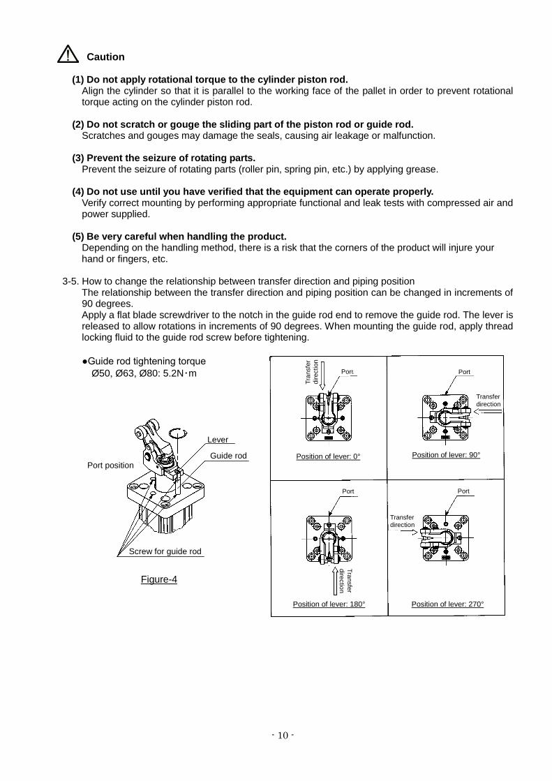
3-5. How to change the relationship between transfer direction and piping position The relationship between the transfer direction and piping position can be changed in increments of
90 degrees. Apply a flat blade screwdriver to the notch in the guide rod end to remove the guide rod. The lever is
released to allow rotations in increments of 90 degrees. When mounting the guide rod, apply thread locking fluid to the guide rod screw before tightening. ●Guide rod tightening torque
Ø50, Ø63, Ø80: 5.2N・m
Guide rod
Lever
Tran
sfer
di
rect
ion
Port
Port Port
Transfer direction
Transfer direction
Transfer direction
Position of lever: 0° Position of lever: 90°
Position of lever: 180° Position of lever: 270°
Port
Port position
Screw for guide rod
Figure-4
- 11 -
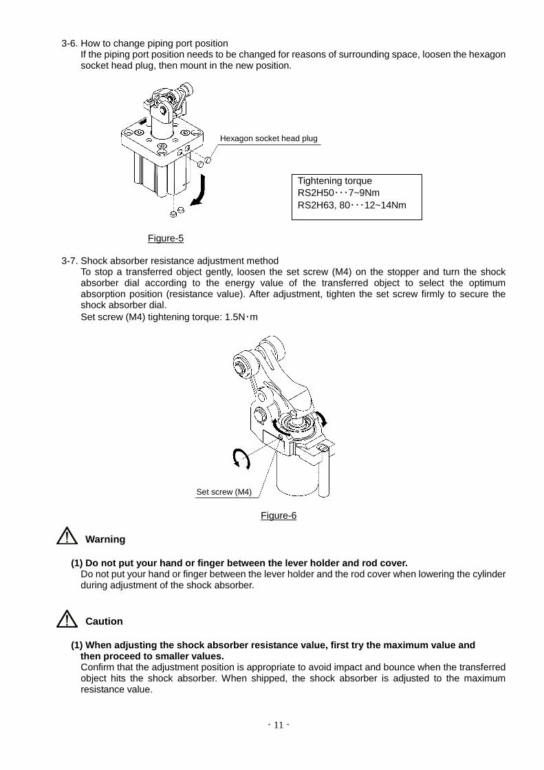
3-6. How to change piping port position If the piping port position needs to be changed for reasons of surrounding space, loosen the hexagon
socket head plug, then mount in the new position.
Figure-5
3-7. Shock absorber resistance adjustment method To stop a transferred object gently, loosen the set screw (M4) on the stopper and turn the shock absorber dial according to the energy value of the transferred object to select the optimum absorption position (resistance value). After adjustment, tighten the set screw firmly to secure the shock absorber dial. Set screw (M4) tightening torque: 1.5N・m
Figure-6
Warning
(1) Do not put your hand or finger between the lever holder and rod cover. Do not put your hand or finger between the lever holder and the rod cover when lowering the cylinder during adjustment of the shock absorber.
Caution
(1) When adjusting the shock absorber resistance value, first try the maximum value and then proceed to smaller values. Confirm that the adjustment position is appropriate to avoid impact and bounce when the transferred object hits the shock absorber. When shipped, the shock absorber is adjusted to the maximum resistance value.
Set screw (M4)
Hexagon socket head plug
Tightening torque RS2H50・・・7~9Nm RS2H63, 80・・・12~14Nm
- 12 -
4. Operation Caution
(1) For cylinders with locking mechanism, do not apply external force from the opposite side
when the lever is locked. Lower the cylinder before adjusting the conveyor or moving the pallet.
(2) For cylinders with locking mechanism, do not allow the pallet and roller to collide when the lever is locked. If the pallet collides with the roller in the locked state, it may cause lever malfunction. (The lever is released when the cylinder is fully retracted.)
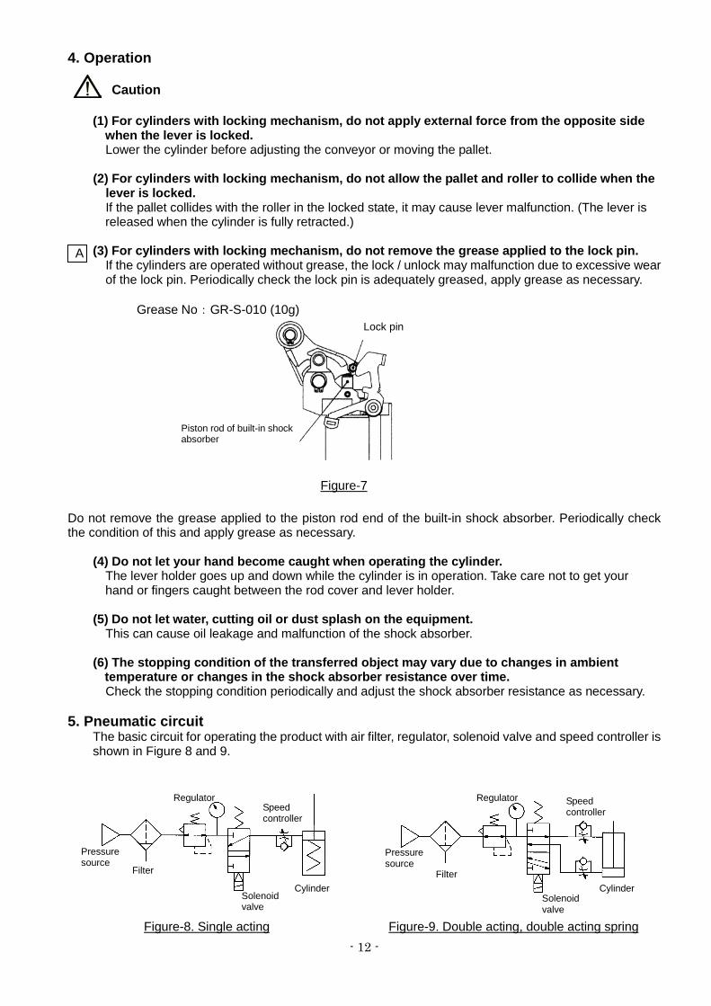
(3) For cylinders with locking mechanism, do not remove the grease applied to the lock pin. If the cylinders are operated without grease, the lock / unlock may malfunction due to excessive wear
of the lock pin. Periodically check the lock pin is adequately greased, apply grease as necessary.
Grease No:GR-S-010 (10g)
Do not remove the grease applied to the piston rod end of the built-in shock absorber. Periodically check the condition of this and apply grease as necessary.
(4) Do not let your hand become caught when operating the cylinder. The lever holder goes up and down while the cylinder is in operation. Take care not to get your hand or fingers caught between the rod cover and lever holder. (5) Do not let water, cutting oil or dust splash on the equipment. This can cause oil leakage and malfunction of the shock absorber. (6) The stopping condition of the transferred object may vary due to changes in ambient
temperature or changes in the shock absorber resistance over time. Check the stopping condition periodically and adjust the shock absorber resistance as necessary. 5. Pneumatic circuit
The basic circuit for operating the product with air filter, regulator, solenoid valve and speed controller is shown in Figure 8 and 9.
Figure-8. Single acting
Pressure source
Filter
Regulator
Solenoid valve
Speed controller
Cylinder
Figure-9. Double acting, double acting spring
Pressure source
Filter
Regulator
Solenoid valve
Speed controller
Cylinder
A
Figure-7
Piston rod of built-in shock absorber
Lock pin
- 13 -
Warning (1) Design the circuit to prevent sudden lurching of driven objects. When a cylinder is driven by an exhaust center type directional control valve or when starting up
after residual pressure is exhausted from the circuit, etc., the piston and its driven object will lurch at high speed if pressure is applied to one side of the cylinder because of the absence of air pressure inside the cylinder. Therefore, select equipment and design circuits to prevent sudden lurching, because there is a danger of human injury and/or damage to equipment when this occurs.
(2) Intermediate stops When an intermediate stopped position is performed with a 3 position closed center type or double
check valve type directional control valve, it is difficult to achieve accurate and precise stopped positions due to the compressibility of air. Furthermore, since valves or cylinders are not guaranteed for zero air leakage, it may not be possible to hold a stopped position for an extended period of time. Please contact SMC if it is necessary to hold a stopped position for an extended period.
Caution (1) Use a speed controller to adjust the cylinder drive speed, gradually increasing from a low
speed to the desired speed setting. 6. Maintenance 6-1. Check items The following checks are required for proper cylinder operation.
1) Smoothness of performance 2) Change of piston speed and cycle time 3) Abnormality of stroke 4) Looseness of cylinder mounting bolt and any other bolts 5) Looseness of the cylinder mounting frame and abnormal deflection 6) External / Internal leakage (output change) 7) Damage to piston rod sliding parts 8) Oil leakage of shock absorber, abnormal impact sound, vibration or external appearance. 9) Looseness of bolt in the locking mechanism, or abnormality of parts.
10) Air filter drainage 11) Lubrication of piston rod and rotating sections (e.g. Lever pin, Roller pin)
12) Auto switch position
Check all the above. If there is any problem, examine the cause and take necessary actions such as further screw tightening and grease application. Contact SMC when the cylinder needs to be repaired.
Warning
(1) Perform maintenance inspection according to the procedures indicated in the operation manual.
If handled improperly, malfunction and damage of machinery or equipment may occur. (2) Maintenance work
If handled improperly, compressed air can be dangerous. Assembly, handling, repair and parts replacement of pneumatic systems should be performed by trained and experienced personnel.
- 14 -
(3) Drain flushing Remove drainage from air filters regularly. (4) Removal of equipment, and supply/exhaust of compressed air When components are removed, first confirm that measures are in place to prevent work pieces from dropping, run-away equipment, etc. Then, cut off the supply pressure and electric power, and exhaust all compressed air from the system using the residual pressure release function.
When machinery is restarted, proceed with caution after confirming that appropriate measures are in place to prevent sudden movement of cylinders.
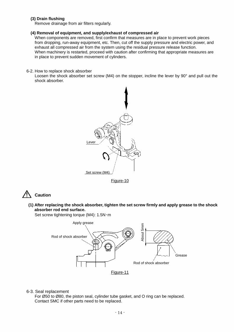
6-2. How to replace shock absorber
Loosen the shock absorber set screw (M4) on the stopper, incline the lever by 90° and pull out the shock absorber.
Figure-10
Caution
(1) After replacing the shock absorber, tighten the set screw firmly and apply grease to the shock absorber rod end surface. Set screw tightening torque (M4): 1.5N・m
Figure-11
6-3. Seal replacement For Ø50 to Ø80, the piston seal, cylinder tube gasket, and O ring can be replaced. Contact SMC if other parts need to be replaced.
Rod of shock absorber
Rod of shock absorber
Grease
Lever
Set screw (M4)
Apply grease
Abo
ut 5
mm
- 15 -
Warning
Seals should be replaced by trained and experienced personnel. The person who does the replacement is responsible for safety once the cylinder is disassembled and reassembled.
Caution
Be careful not to cut hands and fingers on the edges of components when replacing seals. 6-3-1. Disassembly & Reassembly
Caution
Disassemble and reassemble the cylinder over a clean cloth in a clean place. Loosen the four hexagon socket head cap screws with a hexagon wrench. Detach the rod cover and piston rod from the cylinder tube. When reassembling, apply thread locker to the hexagon socket head cap screws and tighten. ●Hexagon socket head cap screw tightening torque Ø50: 12.5N・m Ø63: 24.5N・m Ø80: 42.0N・m
Figure-12
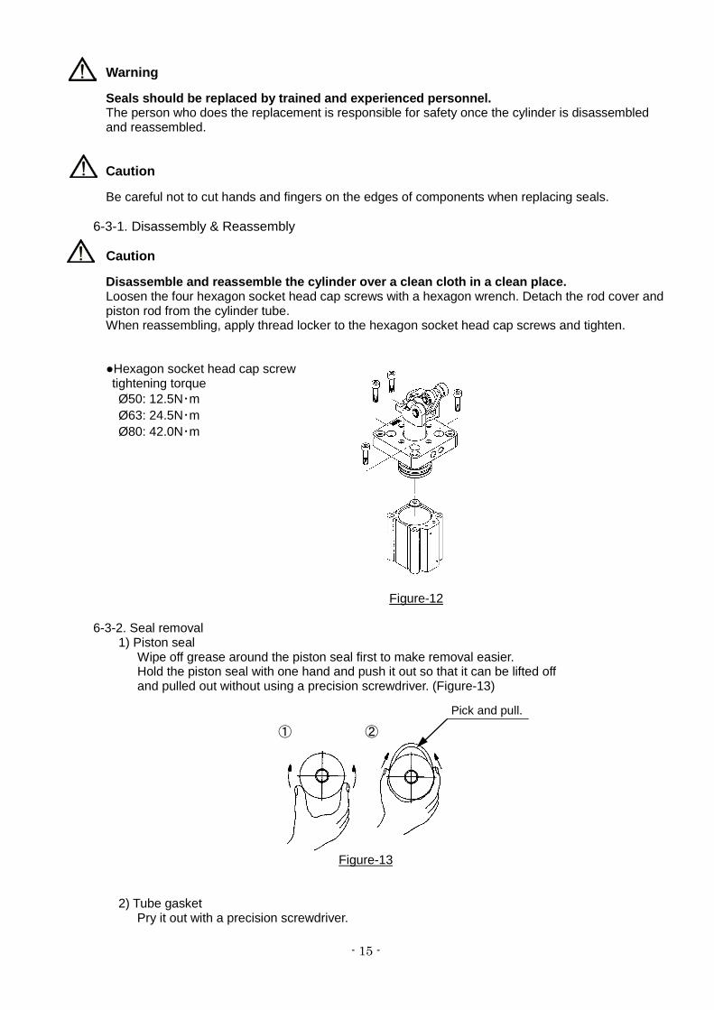
6-3-2. Seal removal 1) Piston seal
Wipe off grease around the piston seal first to make removal easier. Hold the piston seal with one hand and push it out so that it can be lifted off and pulled out without using a precision screwdriver. (Figure-13)
Figure-13
2) Tube gasket
Pry it out with a precision screwdriver.
Pick and pull.
① ②
- 16 -
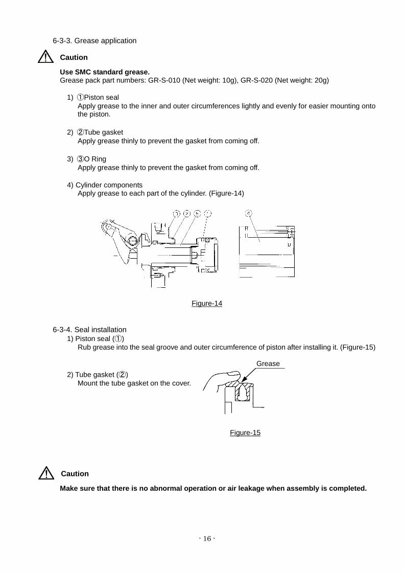
6-3-3. Grease application
Caution
Use SMC standard grease. Grease pack part numbers: GR-S-010 (Net weight: 10g), GR-S-020 (Net weight: 20g)
1) ①Piston seal
Apply grease to the inner and outer circumferences lightly and evenly for easier mounting onto the piston.
2) ②Tube gasket Apply grease thinly to prevent the gasket from coming off.
3) ③O Ring Apply grease thinly to prevent the gasket from coming off.
4) Cylinder components
Apply grease to each part of the cylinder. (Figure-14)
Figure-14
6-3-4. Seal installation
1) Piston seal (①) Rub grease into the seal groove and outer circumference of piston after installing it. (Figure-15)
2) Tube gasket (②) Mount the tube gasket on the cover.
Caution
Make sure that there is no abnormal operation or air leakage when assembly is completed.
Grease
Figure-15
- 17 -
6-4. Consumable parts
6-4-1. Replacement parts Please check the product number of the seal kit on our website.
Caution
Seals are not shipped in sealed packaging for storage, so they should be used within one year.
6-4-2. Seal storage Caution ・Pack seals in a sealed package such as a polyethylene bag and store in a box. ・Avoid direct sunlight and store seals at a low temperature and humidity. Take special
care to isolate and shield them from equipment which generates heat, radiation and ozone. ・Do not pile up a large amount of seals or apply a heavy load, which may result in deformation
or damage. ・White powder may appear on the surface of rubber parts in storage, but this will not affect
the performance. 7. Auto Switch When using the auto switch, refer to the auto switch operation manual.
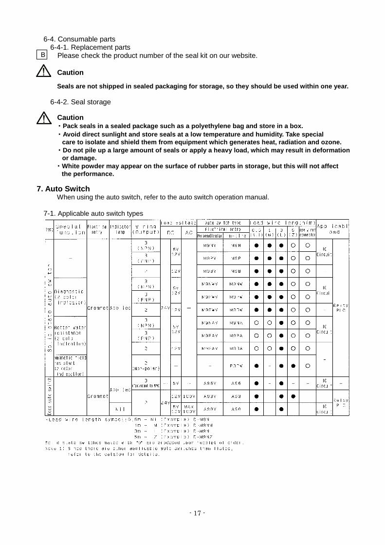
7-1. Applicable auto switch types
B
- 18 -
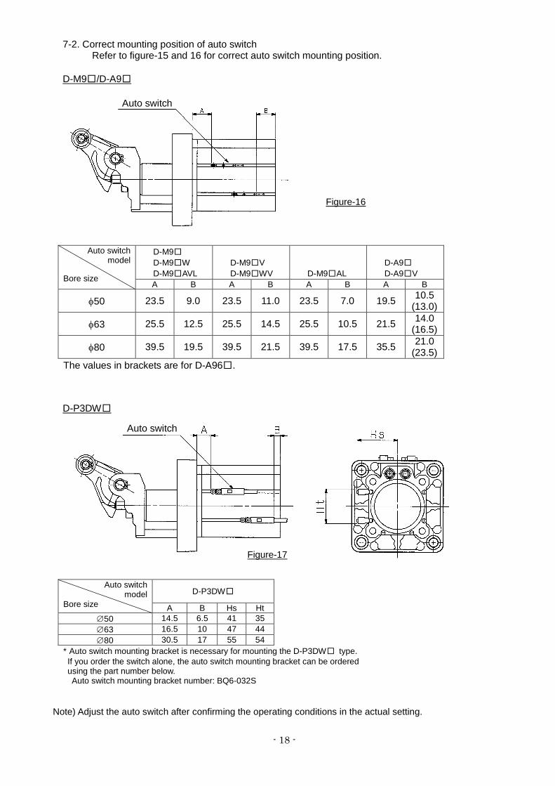
7-2. Correct mounting position of auto switch Refer to figure-15 and 16 for correct auto switch mounting position.
D-M9□/D-A9□
D-P3DW□
Note) Adjust the auto switch after confirming the operating conditions in the actual setting.
Auto switch model
Bore size
D-M9□ D-M9□W D-M9□AVL
D-M9□V D-M9□WV D-M9□AL
D-A9□ D-A9□V
A B A B A B A B
φ50 23.5 9.0 23.5 11.0 23.5 7.0 19.5 10.5 (13.0)
φ63 25.5 12.5 25.5 14.5 25.5 10.5 21.5 14.0 (16.5)
φ80 39.5 19.5 39.5 21.5 39.5 17.5 35.5 21.0 (23.5)
The values in brackets are for D-A96□.
Auto switch
Auto switch
Auto switch model
Bore size D-P3DW□
A B Hs Ht ∅50 14.5 6.5 41 35 ∅63 16.5 10 47 44 ∅80 30.5 17 55 54
* Auto switch mounting bracket is necessary for mounting the D-P3DW□ type. If you order the switch alone, the auto switch mounting bracket can be ordered using the part number below.
Auto switch mounting bracket number: BQ6-032S
Figure-16
Figure-17
- 19 -
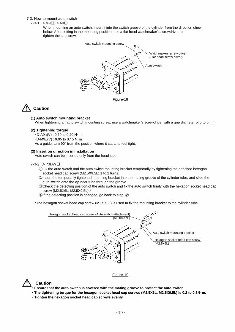
7-3. How to mount auto switch 7-3-1. D-M9□/D-A9□
When mounting an auto switch, insert it into the switch groove of the cylinder from the direction shown below. After setting in the mounting position, use a flat head watchmaker's screwdriver to tighten the set screw.
Figure-18
Caution
(1) Auto switch mounting bracket When tightening an auto switch mounting screw, use a watchmaker’s screwdriver with a grip diameter of 5 to 6mm.
(2) Tightening torque ・D-A9□(V) : 0.10 to 0.20 N・m ・D-M9□(V) : 0.05 to 0.15 N・m As a guide, turn 90° from the position where it starts to feel tight.
(3) Insertion direction in installation Auto switch can be inserted only from the head side.
7-3-2. D-P3DW□ ①Fix the auto switch and the auto switch mounting bracket temporarily by tightening the attached hexagon
socket head cap screw (M2.5X9.5L) 1 to 2 turns. ②Insert the temporarily tightened mounting bracket into the mating groove of the cylinder tube, and slide the
auto switch onto the cylinder tube through the groove. ③Check the detecting position of the auto switch and fix the auto switch firmly with the hexagon socket head cap screw (M2.5X6L, M2.5X9.5L).* ④If the detecting position is changed, go back to step ②.
*The hexagon socket head cap screw (M2.5X6L) is used to fix the mounting bracket to the cylinder tube.
Figure-19
Caution ・Ensure that the auto switch is covered with the mating groove to protect the auto switch. ・The tightening torque for the hexagon socket head cap screws (M2.5X6L, M2.5X9.5L) is 0.2 to 0.3N・m. ・Tighten the hexagon socket head cap screws evenly.
Auto switch
Watchmakers screw driver (Flat head screw driver)
Auto switch mounting screw
Auto switch mounting bracket
Hexagon socket head cap screw (Auto switch attachment) (M2.5×9.5L)
Hexagon socket head cap screw (M2.5×6L)
- 20 -
8. Proximity switch 8-1. Proximity switch specifications / Maker: OMRON Co. Ltd. E2E-X2D1-N Output type Normally open Power supply voltage (Operating voltage range) 12 to 24 VDC (10 to 30 VDC), Ripple 10% or less (P-P) Current consumption (Leakage current) 0.8mA or less Response frequency 1.5 kHz Control output (Switching Capacity) 3 to 100 mA
Indicator light Operation indication (Red LED), Set operation indication (Green LED)
Ambient temperature -25 to 70℃ (No freezing) Operating ambient humidity 35 to 95% RH Residual voltage 3 V or less Note 1) Withstand voltage 1000 VAC Note 2) Vibration Endurance 10 to 55Hz, Double amplitude 1.5mm X, Y, Z direction each 2h Impact Endurance 500 m/s2 (approx. 50 G), X, Y, Z direction each 10 times Enclosure IEC standard IP67 (Immersion proof shape and oil proof shape by JEM standard IP67G)
Note 1) At load current 100 mA and cord length of 2 m Note 2) Between case and whole charging part
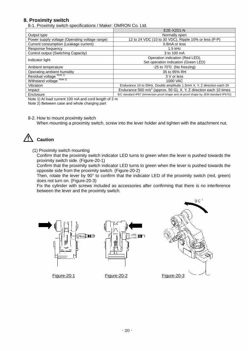
8-2. How to mount proximity switch When mounting a proximity switch, screw into the lever holder and tighten with the attachment nut.
Caution
(1) Proximity switch mounting Confirm that the proximity switch indicator LED turns to green when the lever is pushed towards the proximity switch side. (Figure-20-1) Confirm that the proximity switch indicator LED turns to green when the lever is pushed towards the opposite side from the proximity switch. (Figure-20-2) Then, rotate the lever by 90° to confirm that the indicator LED of the proximity switch (red, green) does not turn on. (Figure-20-3) Fix the cylinder with screws included as accessories after confirming that there is no interference between the lever and the proximity switch.
Figure-20-1 Figure-20-2 Figure-20-3
- 21 -
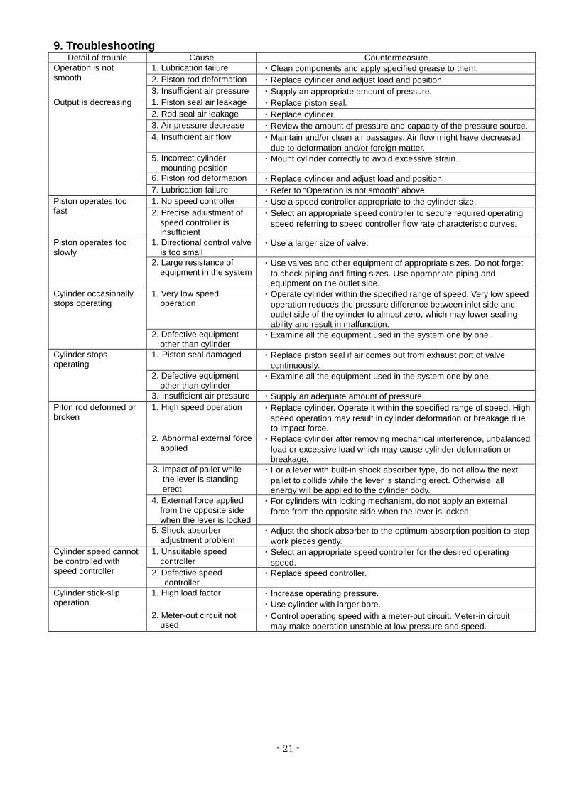
9. Troubleshooting Detail of trouble Cause Countermeasure
Operation is not smooth
1. Lubrication failure ・Clean components and apply specified grease to them. 2. Piston rod deformation ・Replace cylinder and adjust load and position. 3. Insufficient air pressure ・Supply an appropriate amount of pressure.
Output is decreasing 1. Piston seal air leakage ・Replace piston seal. 2. Rod seal air leakage ・Replace cylinder 3. Air pressure decrease ・Review the amount of pressure and capacity of the pressure source. 4. Insufficient air flow ・Maintain and/or clean air passages. Air flow might have decreased
due to deformation and/or foreign matter. 5. Incorrect cylinder
mounting position ・Mount cylinder correctly to avoid excessive strain.
6. Piston rod deformation ・Replace cylinder and adjust load and position. 7. Lubrication failure ・Refer to “Operation is not smooth” above.
Piston operates too fast
1. No speed controller ・Use a speed controller appropriate to the cylinder size. 2. Precise adjustment of
speed controller is insufficient
・Select an appropriate speed controller to secure required operating speed referring to speed controller flow rate characteristic curves.
Piston operates too slowly
1. Directional control valve is too small
・Use a larger size of valve.
2. Large resistance of equipment in the system
・Use valves and other equipment of appropriate sizes. Do not forget to check piping and fitting sizes. Use appropriate piping and equipment on the outlet side.
Cylinder occasionally stops operating
1. Very low speed operation
・Operate cylinder within the specified range of speed. Very low speed operation reduces the pressure difference between inlet side and outlet side of the cylinder to almost zero, which may lower sealing ability and result in malfunction.
2. Defective equipment other than cylinder
・Examine all the equipment used in the system one by one.
Cylinder stops operating
1. Piston seal damaged ・Replace piston seal if air comes out from exhaust port of valve continuously.
2. Defective equipment other than cylinder
・Examine all the equipment used in the system one by one.
3. Insufficient air pressure ・Supply an adequate amount of pressure. Piton rod deformed or broken
1. High speed operation ・Replace cylinder. Operate it within the specified range of speed. High speed operation may result in cylinder deformation or breakage due to impact force.
2. Abnormal external force applied
・Replace cylinder after removing mechanical interference, unbalanced load or excessive load which may cause cylinder deformation or breakage.
3. Impact of pallet while the lever is standing erect
・For a lever with built-in shock absorber type, do not allow the next pallet to collide while the lever is standing erect. Otherwise, all energy will be applied to the cylinder body.
4. External force applied from the opposite side when the lever is locked
・For cylinders with locking mechanism, do not apply an external force from the opposite side when the lever is locked.
5. Shock absorber adjustment problem
・Adjust the shock absorber to the optimum absorption position to stop work pieces gently.
Cylinder speed cannot be controlled with speed controller
1. Unsuitable speed controller
・Select an appropriate speed controller for the desired operating speed.
2. Defective speed controller
・Replace speed controller.
Cylinder stick-slip operation
1. High load factor
・Increase operating pressure. ・Use cylinder with larger bore.
2. Meter-out circuit not used
・Control operating speed with a meter-out circuit. Meter-in circuit may make operation unstable at low pressure and speed.
- 22 -
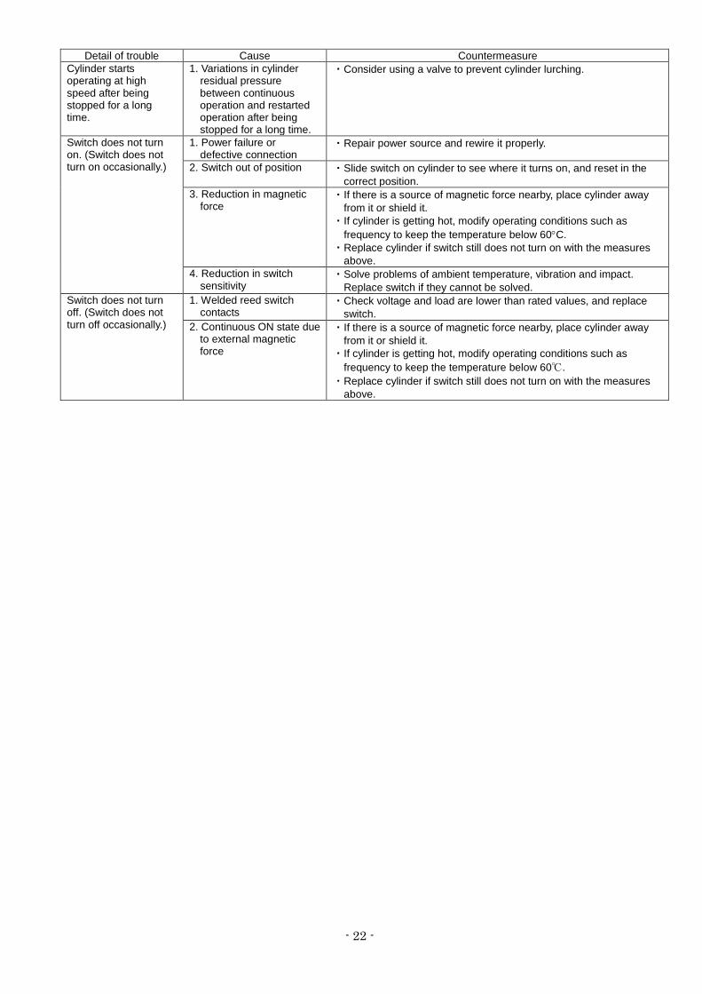
Detail of trouble Cause Countermeasure Cylinder starts operating at high speed after being stopped for a long time.
1. Variations in cylinder residual pressure
between continuous operation and restarted operation after being stopped for a long time.
・Consider using a valve to prevent cylinder lurching.
Switch does not turn on. (Switch does not turn on occasionally.)
1. Power failure or defective connection
・Repair power source and rewire it properly.
2. Switch out of position ・Slide switch on cylinder to see where it turns on, and reset in the correct position.
3. Reduction in magnetic force
・If there is a source of magnetic force nearby, place cylinder away from it or shield it.
・If cylinder is getting hot, modify operating conditions such as frequency to keep the temperature below 60°C.
・Replace cylinder if switch still does not turn on with the measures above.
4. Reduction in switch sensitivity
・Solve problems of ambient temperature, vibration and impact. Replace switch if they cannot be solved.
Switch does not turn off. (Switch does not turn off occasionally.)
1. Welded reed switch contacts
・Check voltage and load are lower than rated values, and replace switch.
2. Continuous ON state due to external magnetic force
・If there is a source of magnetic force nearby, place cylinder away from it or shield it.
・If cylinder is getting hot, modify operating conditions such as frequency to keep the temperature below 60℃.
・Replace cylinder if switch still does not turn on with the measures above.
- 23 -
Revision history Revision A: Addition of Caution for product with
locking mechanism (P.12) Revision B: Seal kit number deletion(P.17,23) Wrapping of sealant tape is
changed.(P.9)
4-14-1, Sotokanda, Chiyoda-ku, Tokyo 101-0021 JAPAN Tel: + 81 3 5207 8249 Fax: +81 3 5298 5362 URL http://www.smcworld.com Note: Specifications are subject to change without prior notice and any obligation on the part of the manufacturer. © 2008 SMC Corporation All Rights Reserved