RL RODLESS CYLINDER - TOP AIR RL RODLESS CYLINDER ... For cylinders with linear guides or brakes,...
16
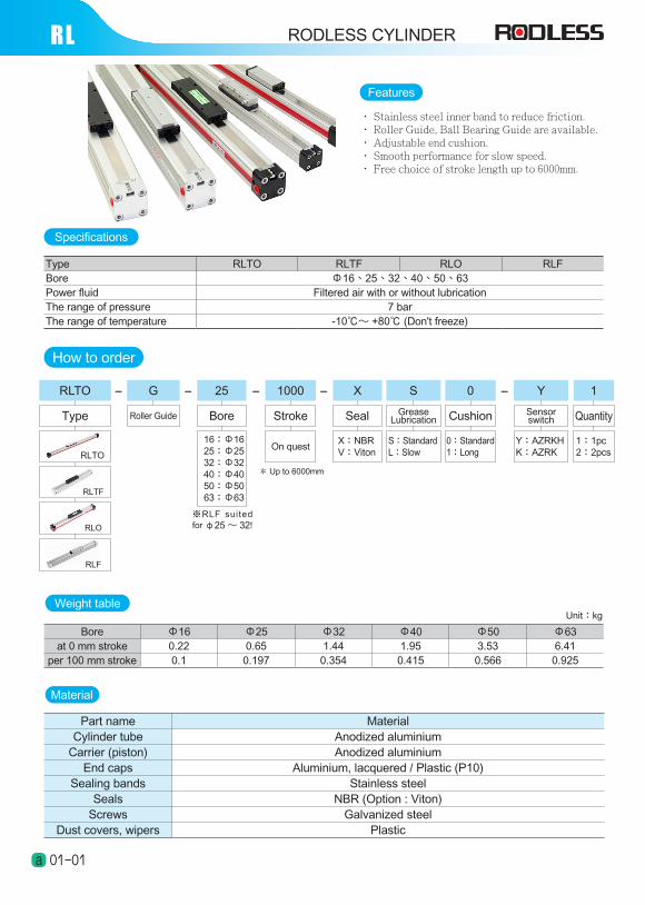
RL RODLESS CYLINDER Type RLTO RLTF RLO RLF Bore Φ16、25、32、40、50、63 Power fluid Filtered air with or without lubrication The range of pressure 7 bar The range of temperature -10℃~ +80℃ (Don't freeze) Weight table Bore Φ16 Φ25 Φ32 Φ40 Φ50 Φ63 at 0 mm stroke 0.22 0.65 1.44 1.95 3.53 6.41 per 100 mm stroke 0.1 0.197 0.354 0.415 0.566 0.925 Unit:kg 01-01 a ‧ Stainless steel inner band to reduce friction. ‧ Roller Guide, Ball Bearing Guide are available. ‧ Adjustable end cushion. ‧ Smooth performance for slow speed. ‧ Free choice of stroke length up to 6000mm. Features Material Part name Material Cylinder tube Anodized aluminium Carrier (piston) Anodized aluminium End caps Aluminium, lacquered / Plastic (P10) Sealing bands Stainless steel Seals NBR (Option : Viton) Screws Galvanized steel Dust covers, wipers Plastic Specifications How to order Type 1 Quantity 25 Bore 16:Φ16 25:Φ25 32:Φ32 40:Φ40 50:Φ50 63:Φ63 - 1:1pc 2:2pcs X Seal X:NBR V:Viton S Grease Lubrication S:Standard L:Slow 1000 Stroke On quest - * Up to 6000mm Y Sensor switch Y:AZRKH K:AZRK - - 0 Cushion 0:Standard 1:Long G - Roller Guide ※RLF suited for φ25 ~ 32! RLF RLO RLTF RLTO RLTO
Transcript of RL RODLESS CYLINDER - TOP AIR RL RODLESS CYLINDER ... For cylinders with linear guides or brakes,...
RL RODLESS CYLINDER
Type RLTO RLTF RLO RLFBore Φ16、25、32、40、50、63Power fluid Filtered air with or without lubricationThe range of pressure 7 barThe range of temperature -10℃~ +80℃ (Don't freeze)
Weight table
Bore Φ16 Φ25 Φ32 Φ40 Φ50 Φ63at 0 mm stroke 0.22 0.65 1.44 1.95 3.53 6.41
per 100 mm stroke 0.1 0.197 0.354 0.415 0.566 0.925
Unit:kg
01-01a
‧ Stainless steel inner band to reduce friction.‧ Roller Guide, Ball Bearing Guide are available.‧ Adjustable end cushion.‧ Smooth performance for slow speed.‧ Free choice of stroke length up to 6000mm.
Features
Material
Part name MaterialCylinder tube Anodized aluminium
Carrier (piston) Anodized aluminiumEnd caps Aluminium, lacquered / Plastic (P10)
Sealing bands Stainless steelSeals NBR (Option : Viton)
Screws Galvanized steelDust covers, wipers Plastic
Specifications
How to order
Type
1
Quantity
25
Bore
16:Φ16 25:Φ25 32:Φ32 40:Φ40 50:Φ50 63:Φ63
-
1:1pc2:2pcs
X
Seal
X:NBRV:Viton
SGrease
Lubrication
S:StandardL:Slow
1000
Stroke
On quest
-
* Up to 6000mm
YSensorswitch
Y:AZRKHK:AZRK
- -0
Cushion
0:Standard1:Long
G -
Roller Guide
※RLF sui ted for φ25 ~ 32!
RLF
RLO
RLTF
RLTO
RLTO
RLRODLESS CYLINDER
01-02a
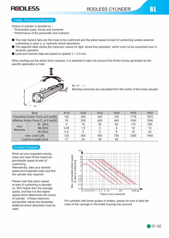
Loads, Forces and Moments
Bore Φ16 Φ25 Φ32 Φ40 Φ50 Φ63Theoretical Action Force at 6 bar[N] 120 295 483 754 1178 1870effektive Action Force FA at 6 bar[N] 78 250 420 640 1000 1550
max. Moments
M [Nm] 4 15 30 60 115 200Ms [Nm] 0.45 1.5 3 6 10 12Mv [Nm] 0.5 3 5 8 15 24
max. Load L[N] 120 300 450 750 1200 1650Cushion Length [mm] 17 30 35 45
M = F ‧ r Bending moments are calculated from the centre of the linear actuator
Choice of cylinder is decided by:‧Permissible loads, forces and moments‧Performance of the pneumatic end cushions
● The main factors here are the mass to be cushioned and the piston speed at start of cushioning (unless external cushioning is used, e. g. hydraulic shock absorbers).● The adjacent table shows the maximum values for light, shock-free operation, which must not be exceeded even in dynamic operation.● Load and moment data are based on speeds V ≤ 0.5 m/s.
When working out the action force required, it is essential to take into account the friction forces generated by the specific application or load.
Cushion Diagram
0.10.1
0.20.3 0.5
0.2
0.30.40.5
1
2
345
* Mass to be cushioned
Ma
x. p
erm
issi
ble
pis
ton
sp
ee
d
at st
art
of cu
shio
nin
g
1 2 3 5 10 100 1000 kg
m/s
D16D25
D32D40
D50 D63
For cylinders with linear guides or brakes, please be sure to take the mass of the carriage or the brake housing into account.
Work out your expected moving mass and read off the maximum permissible speed at start of cushioning.Alternatively, take your desired speed and expected mass and find the cylinder size required.
Please note that piston speed at start of cushioning is typically ca. 50% higher than the average speed, and that it is this higher speed which determines the choice of cylinder. If these maximum permissible values are exceeded, additonal shock absorbers must be used.
01-03a
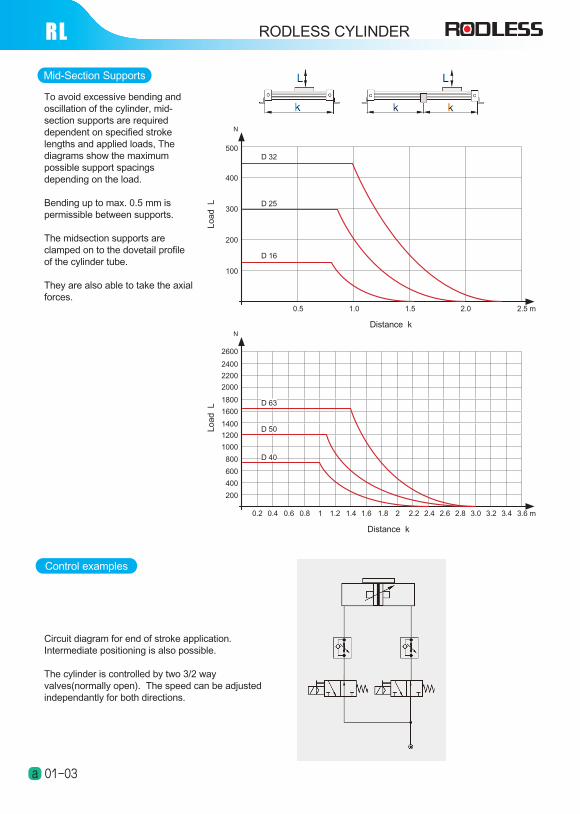
Mid-Section Supports
0.2
200
0.4 0.6 0.8
400
600
800
1000
1400
1800
2000
2200
2400
Distance k
Lo
ad
L
1 1.2 1.4 1.6 1.8 2.2 2.6 3.0 3.2 3.42.82.42 3.6 m
N
1200
1600
2600
D 40
D 50
D 63
To avoid excessive bending and oscillation of the cylinder, mid-section supports are required dependent on specified stroke lengths and applied loads, The diagrams show the maximum possible support spacings depending on the load.
Bending up to max. 0.5 mm is permissible between supports.
The midsection supports are clamped on to the dovetail profile of the cylinder tube.
They are also able to take the axial forces.
100
0.5
200
300
400
500
Distance k
Lo
ad
L
1.0 1.5 2.0 2.5 m
N
D 16
D 25
D 32
RL
Control examples
Circuit diagram for end of stroke application. Intermediate positioning is also possible.
The cylinder is controlled by two 3/2 way valves(normally open). The speed can be adjusted independantly for both directions.
RODLESS CYLINDER
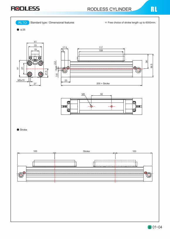
RLTO
● φ25
● Stroke
117109
200 + Stroke23
17.59
41
33
19
27
M5x15
27
41
21
.5
3.6
2.2
56
.5
36
50M5
Stroke100 100
Standard type / Dimensional features * Free choice of stroke length up to 6000mm.
RLRODLESS CYLINDER
01-04a
01-05a
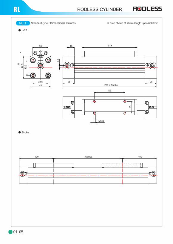
● φ25
RLTF
● Stroke
100 Stroke 100
1171633
32.5
45
32
.5
47
.558
25
200 + Stroke
3.6
25
65
M5x8
25
Standard type / Dimensional features * Free choice of stroke length up to 6000mm.
RL RODLESS CYLINDER
RLRODLESS CYLINDER
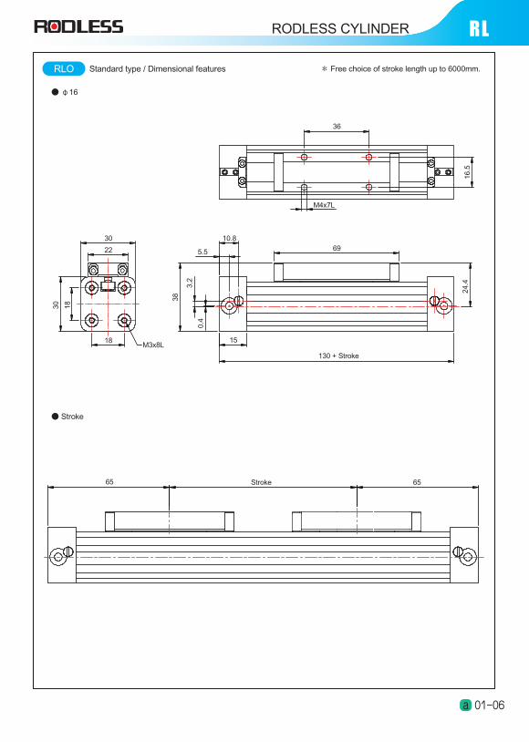
RLO
● φ16
● Stroke
M4x7L
M3x8L
36
16
.5
69
10.8
5.5
130 + Stroke
15
24
.4
38
3.2
0.4
18
1830
22
30
Stroke 6565
Standard type / Dimensional features * Free choice of stroke length up to 6000mm.
01-06a
RL RODLESS CYLINDER
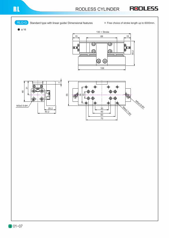
● φ16
RLO-G
130 + Stroke
6915 15
55
.2
106
30
40
60
70
15
36
55
M4x0.7-6H
M5x0.8-6H25.2
40.2
M3x0.5-6H
46
31
7
Standard type with linear guide/ Dimensional features * Free choice of stroke length up to 6000mm.
01-07a
RLRODLESS CYLINDER
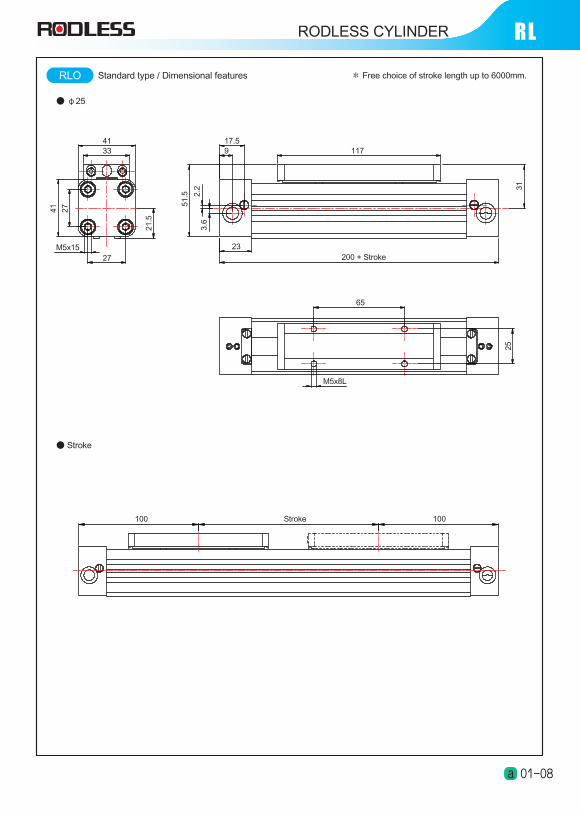
● φ25
RLO
● Stroke
51
.5 2.2
3.6
27
41
21
.54133
27M5x15 23
17.59 117
200 + Stroke
31
65
M5x8L
25
Stroke 100100
Standard type / Dimensional features * Free choice of stroke length up to 6000mm.
01-08a
RODLESS CYLINDERRL RODLESS CYLINDER
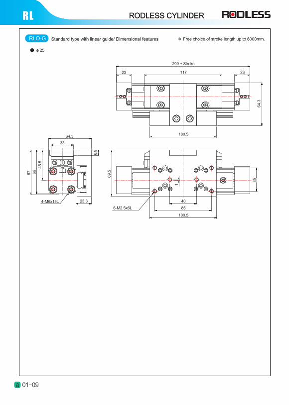
● φ25
01-09a
200 + Stroke
11723 23
100.5
64
.33
5
1
69
.5
6-M2.5x6L
40
85
100.5
23.34-M6x15L
8.5
64.3
33
45
.5
66
67
RLO-G Standard type with linear guide/ Dimensional features * Free choice of stroke length up to 6000mm.
RODLESS CYLINDER RLRODLESS CYLINDER
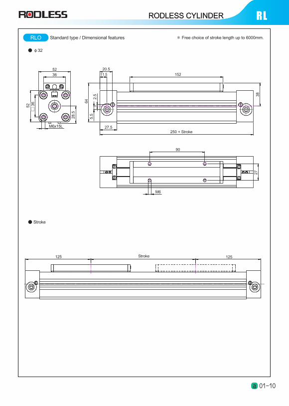
RLO
● φ32
● Stroke
M6
M6x15L
2.5
5.5
64
28
.5
□3
65
2
3652 20.5
11.5 152
250 + Stroke27.5
38
90
27
Stroke 125125
Standard type / Dimensional features * Free choice of stroke length up to 6000mm.
01-10a
RODLESS CYLINDERRL RODLESS CYLINDER
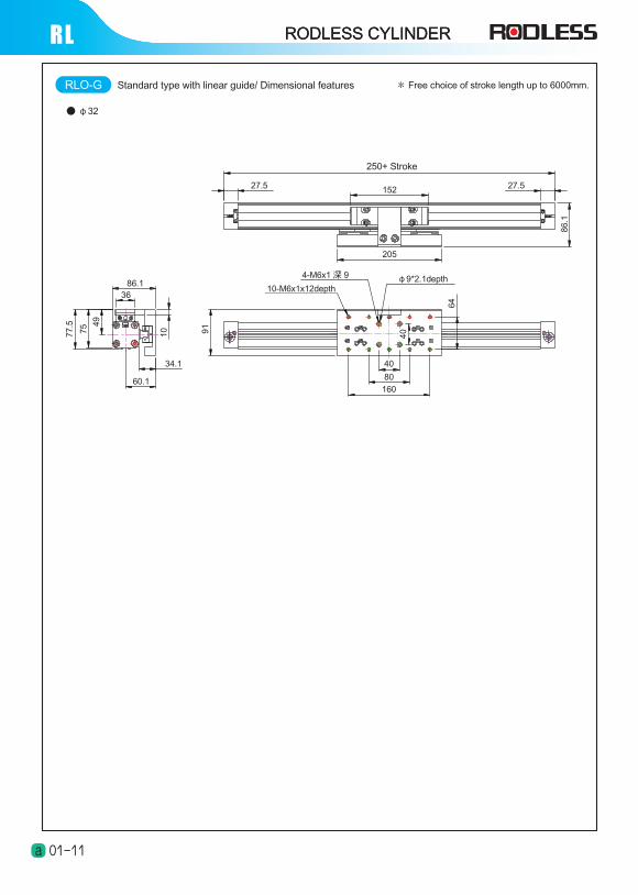
RLO-G
● φ32
250+ Stroke
91
77
.5
75 4
9
10
64
40
86
.1
27.5152
205
27.5
4-M6x1 深 9
10-M6x1x12depthφ9*2.1depth
40
80
160
86.136
34.1
60.1
Standard type with linear guide/ Dimensional features * Free choice of stroke length up to 6000mm.
01-11a
RODLESS CYLINDER RLRODLESS CYLINDER
● Stroke
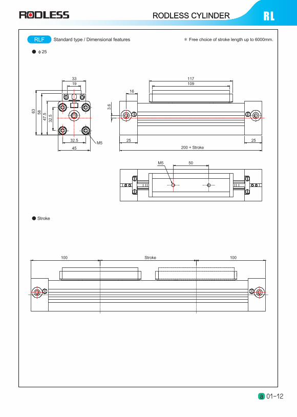
● φ25
RLF
117109
16
3.6
3319
M532.5
45
25
200 + Stroke
25
63
58
47
.5
32
.5
50M5
Stroke 100100
Standard type / Dimensional features * Free choice of stroke length up to 6000mm.
01-12a
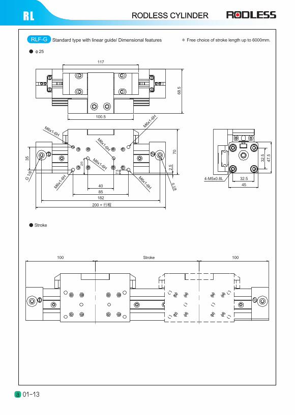
RLF-G
● φ25
● Stroke
G 1/8
117
100.5
68
.5
40
85
182
200 + 行程
32.5
45
70
2.5
32
.5
47
.5
4-M5x0.8L
7.5
M6x1-6H
M6x1-6H
M6x1-6H
M6x1-6H
35
M6x
1-6H
M6x
1-6H
25
G 1
/8
Stroke 100100
RODLESS CYLINDERRL RODLESS CYLINDER
Standard type with linear guide/ Dimensional features * Free choice of stroke length up to 6000mm.
01-13a
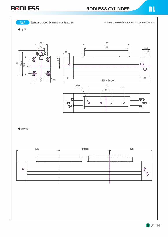
● φ32
RLF
● Stroke
M6
135
125 22.5
14
31250 + Stroke
19
314054
36
19
M5x7
4.7
4056
.872
68
.8
100
30
Stroke 125125
RODLESS CYLINDER RLRODLESS CYLINDER
Standard type / Dimensional features * Free choice of stroke length up to 6000mm.
01-14a
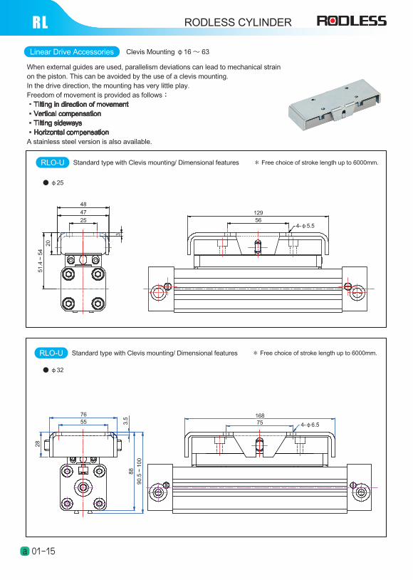
RLLinear Drive Accessories Clevis Mounting φ16 ~ 63
When external guides are used, parallelism deviations can lead to mechanical strain on the piston. This can be avoided by the use of a clevis mounting.In the drive direction, the mounting has very little play.Freedom of movement is provided as follows:‧Tilting in direction of movement ‧Vertical compensation‧Tilting sideways‧Horizontal compensationA stainless steel version is also available.
RODLESS CYLINDER
01-15a
● φ25
12956
4-φ5.5
48
47
25
20
51
.4 ~
54
3
● φ32
16875 4-φ6.5
7655 3
.58
8
90
.5 ~
10
0
28
RLO-U Standard type with Clevis mounting/ Dimensional features * Free choice of stroke length up to 6000mm.
RLO-U Standard type with Clevis mounting/ Dimensional features * Free choice of stroke length up to 6000mm.
Linear Drive Accessories
Dimensional Talbe
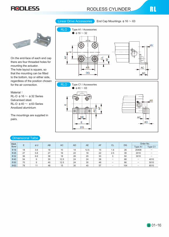
RLEnd Cap Mountings φ16 ~ 63
RLO Type A1 / Accessories
● φ16 ~ 32
RLO Type C1 / Accessories
● φ40 ~ 63
On the end-face of each end cap there are four threaded holes for mounting the actuator.The hole layout is square, so that the mounting can be fitted to the bottom, top or either side, regardless of the position chosen for the air connection.
Material:RL-O φ16 ~ φ32 SeriesGalvanised steel.RL-O φ40 ~ φ63 SeriesAnodized aluminium
The mountings are supplied in pairs.
MarkBore
E φU AB AC AD AE AF CL DGOrder No.
Type A1 Type C1
Φ16 18 3.6 18 10 14 12.5 15 1.6 26 20408 -
Φ25 27 5.8 27 16 22 18 22 2.5 39 2010 -
Φ32 36 6.6 36 18 26 20 30 3 50 3010 -
Φ40 54 9 30 12.5 24 24 38 - 68 - 4010
Φ50 70 9 40 12.5 24 30 48 - 86 - 5010
Φ63 78 11 48 15 30 40 57 - 104 - 6010
RODLESS CYLINDER
01-16a