HAZARDOUS LOCATION TELEMETRY EQUIPMENTWe also have an engineering test laboratory equipped with...
31
HAZARDOUS LOCATION TELEMETRY EQUIPMENT
Transcript of HAZARDOUS LOCATION TELEMETRY EQUIPMENTWe also have an engineering test laboratory equipped with...

HAZARDOUSLOCATION
TELEMETRY EQUIPMENT
ANH72
Frequency Range 2.35 - 2.55 GHzImpedance (nominal) 50Ω @ 2.45 GHzVSWR (average) 1.13 : 1 (Average)Gain max 2.00 dBi

COMPANY
SOLEXY specializes in devices and patented technology for radio and buss transmissions in hazardous classified areas such as refi-neries, chemical plants, mines, off shore rigs and other potentially hazardous rated areas.SOLEXY has two Operation Centers:- Cincinnati, Ohio, USA, where the Research and Development of components, and antennas are engineered. Manufacturing of stan-dard components is also based here. Managed by Mr. Mark Peters, this location services the US, Canadian and Mexican markets.- Desenzano del Garda, Italy, where the systems integration manu-facturing is located. Managed by Mr. Giovanni Soldo, this location services European, Asian, African, Australian, Central America and South American markets.
We are known for the first wireless industrial products on the market. We originally specialized in limit switches, but eventually developed and sold other sensors. To enable this technology to be used in our typical markets of refineries, chemical plants and up-stream processes, we realized the need to develop products that would allow use of this wireless technology in classified areas. Our flameproof intrinsically safe barriers for radios and busses al-lowed transmission of RF signals into classified “Hazardous Areas”. Expanding on the need of this technology in industrial environmen-ts, we developed a line of industrial antennas that meets the de-manding requirements and hostility of the process environment. Expanding our patented technology and realizing the demand to protect other signals, we developed a solution for Ethernet. It is now possible to transmit Ethernet signals from explosion proof enclosures or purge panel systems into a hazardous area with the use of our Passive Ethernet barrier, without the cost of additional sealing devices, area rated conduit systems, or additional power.
A C
om
pa
ny
Dr
ive
n b
y I
nn
ov
at
ion
, r
ew
ar
de
d b
y C
us
to
me
r S
at
isf
ac
tio
n
ANH72
Frequency Range 2.35 - 2.55 GHzImpedance (nominal) 50Ω @ 2.45 GHzVSWR (average) 1.13 : 1 (Average)Gain max 2.00 dBi
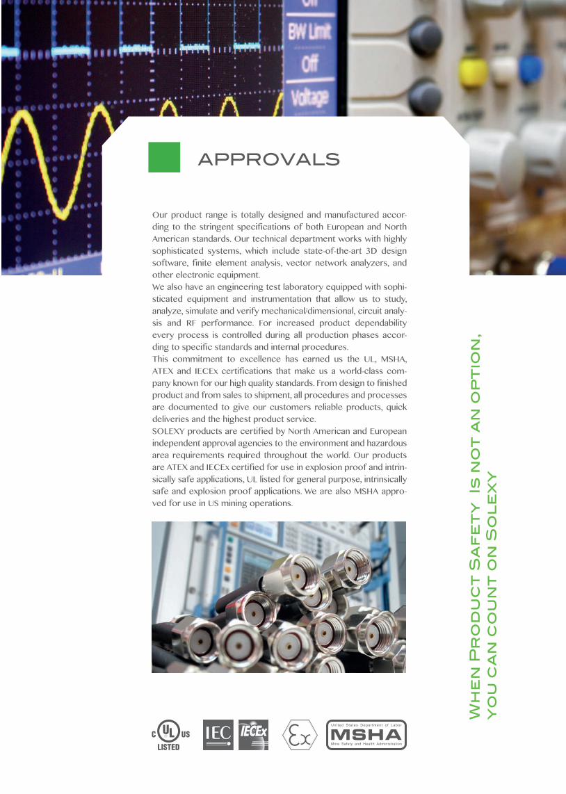
Our product range is totally designed and manufactured accor-ding to the stringent specifications of both European and North American standards. Our technical department works with highly sophisticated systems, which include state-of-the-art 3D design software, finite element analysis, vector network analyzers, and other electronic equipment.We also have an engineering test laboratory equipped with sophi-sticated equipment and instrumentation that allow us to study, analyze, simulate and verify mechanical/dimensional, circuit analy-sis and RF performance. For increased product dependability every process is controlled during all production phases accor-ding to specific standards and internal procedures.This commitment to excellence has earned us the UL, MSHA, ATEX and IECEx certifications that make us a world-class com-pany known for our high quality standards. From design to finished product and from sales to shipment, all procedures and processes are documented to give our customers reliable products, quick deliveries and the highest product service. SOLEXY products are certified by North American and European independent approval agencies to the environment and hazardous area requirements required throughout the world. Our products are ATEX and IECEx certified for use in explosion proof and intrin-sically safe applications, UL listed for general purpose, intrinsically safe and explosion proof applications. We are also MSHA appro-ved for use in US mining operations.
APPROVALS
Wh
en
Pr
od
uc
t S
af
et
y I
s n
ot
an
op
tio
n,
yo
u c
an
co
un
t o
n S
ol
ex
y
ANH72
Frequency Range 2.35 - 2.55 GHzImpedance (nominal) 50Ω @ 2.45 GHzVSWR (average) 1.13 : 1 (Average)Gain max 2.00 dBi
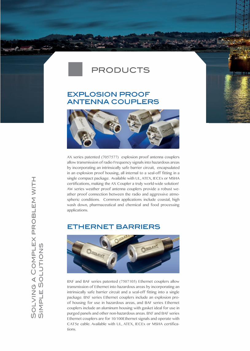
AX series patented (7057577) explosion proof antenna couplers allow transmission of radio Frequency signals into hazardous areas by incorporating an intrinsically safe barrier circuit, encapsulated in an explosion proof housing, all internal to a seal-off fitting in a single compact package. Available with UL, ATEX, IECEx or MSHA certifications, making the AX Coupler a truly world-wide solution!AW series weather proof antenna couplers provide a robust we-ather proof connection between the radio and aggressive atmo-spheric conditions. Common applications include coastal, high wash down, pharmaceutical and chemical and food processing applications.
EXPLOSION PROOF ANTENNA COUPLERS
BXF and BAF series patented (7507105) Ethernet couplers allow transmission of Ethernet into hazardous areas by incorporating an intrinsically safe barrier circuit and a seal-off fitting into a single package. BXF series Ethernet couplers include an explosion pro-of housing for use in hazardous areas, and BAF series Ethernet couplers include an aluminum housing with gasket ideal for use in purged panels and other non-hazardous areas. BXF and BAF series Ethernet couplers are for 10/100Ethernet signals and operate with CAT5e cable. Available with UL, ATEX, IECEx or MSHA certifica-tions.
ETHERNET BARRIERS
PRODUCTS
So
lv
ing
a C
om
pl
ex
pr
ob
le
m w
ith
S
imp
le
So
lu
tio
ns
ANH72
Frequency Range 2.35 - 2.55 GHzImpedance (nominal) 50Ω @ 2.45 GHzVSWR (average) 1.13 : 1 (Average)Gain max 2.00 dBi
ANH and ANF series antennas are hand built and tuned for the best performance. The rugged construction of the ANH will stand up to high levels of abuse, and the flexible design of the ANF “gives” to impacts to prevent damage and misalignment of the antenna. Their sealed UV and corrosion resistant housings and nickel plated fittings with gold contacts provide a reliable RF connection in ho-stile environments.
ANTENNAS
WS and WA series hazardous area enclosures are available as Jun-ction boxes, Wi-Fi hotspots configured as a master, client or repe-ater, Radio Modems that can be used to interface remote serial ports and digital and analog I/O from the field to remote locations and totally wire free transmission of RF signals. Optional Intrinsi-cally Safe Ethernet signals can be added with minimal cost of in-stallation. Radio modems with remote I/O can transmit and recei-ve using Modbus protocol as a standard option. Available in either a stainless steel (WS) or powder coated aluminum (WA) explosion proof rated enclosure. All Approved for ATEX, IECEx and UL.
hazardous areawireless systems
Pr
od
uc
ts
th
at
yo
u c
an
re
ly
on
, S
ign
al
s y
ou
ca
n c
ou
nt
on
ANH72
Frequency Range 2.35 - 2.55 GHzImpedance (nominal) 50Ω @ 2.45 GHzVSWR (average) 1.13 : 1 (Average)Gain max 2.00 dBi
ww
w.S
OL
EX
Y.n
et
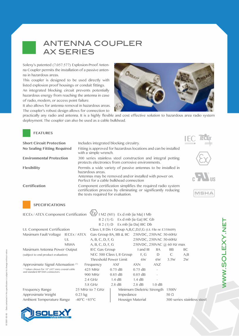
Solexy’s patented (7.057.577) Explosion-Proof Anten-na Coupler permits the installation of a passive anten-na in hazardous areas. This coupler is designed to be used directly with listed explosion proof housings or conduit fittings.An integrated blocking circuit prevents potentially hazardous energy from reaching the antenna in case of radio, modem, or access point failure.It also allows for antenna removal in hazardous areas.The coupler’s robust design allows for connection to
Short Circuit Protection Includes integrated blocking circuitry. No Sealing Fitting Required Fitting is approved for hazardous locations and can be installed
with a simple wrench.Environmental Protection 300 series stainless steel construction and integral potting
protects electronics from corrosive environments.Flexibility Permits a wide variety of passive antennas to be installed in
hazardous areas. Antennas may be removed and/or installed with power on. Perfect for a cable bulkhead connectionCertification Component certification simplifies the required radio system
certification process by eliminating or significantly reducing the tests required for evaluation.
FEATURES
SPECIFICATIONS
B130
01-0
0-06
- D
ata
cont
aine
d in
this
spec
ifica
tion
is su
bjec
t to
chan
ge w
ithou
t not
ice
practically any radio and antenna. It is a highly flexible and cost effective solution to hazardous area radio system deployment. The coupler can also be used as a cable bulkhead.
IECEx / ATEX Component Certification I M2 (M1) Ex d mb [ia Ma] I Mb II 2 (1) G Ex d mb [ia Ga] IIC Gb II 2 (1) D Ex mb [ia Da] IIIC DbUL Component Certification Class I, II Div I Group A,B,C,D,F,G (UL File nr. E358609)Maximum Fault Voltage IECEx / ATEX Gas Group IIA, IIB & IIC 250VDC, 250VAC 50-60Hz UL A, B, C, D, F, G 250VDC, 250VAC 50-60Hz MSHA A, B, C, D, F, G 250VDC, 250VAC @ 60 Hz maxMaximum Antenna Power Output IEC Gas Group I and III IIA IIB IIC(subject to end product evaluation) NEC 500 Class I, II Group F, G D C A,B Threshold Power Limit 6W 6W 3.5W 2WApproximate Signal Attenuation (1) Frequency AXF AXN AXZ 425 MHz 0.75 dB 0.75 dB - 900 MHz 0.85 dB 0.85 dB - 2.4 GHz 1.4 dB 1.4 dB - 5.8 GHz 2.8 dB 2.8 dB 1.0 dBFrequency Range 25 MHz to 7 GHz Minimum Dieletric Strength 1500VApproximate Weight 0.23 kg Impedance 50 ΩAmbient Temperature Range -40°C +85°C Housign Material 300 series stainless steel
(1) Values shown for 18” (457 mm) coaxial cableand standard RP-SMA connectors
ANTENNA COUPLERAX SERIES
ANH72
Frequency Range 2.35 - 2.55 GHzImpedance (nominal) 50Ω @ 2.45 GHzVSWR (average) 1.13 : 1 (Average)Gain max 2.00 dBi
ANTENNA COUPLERAX SERIES
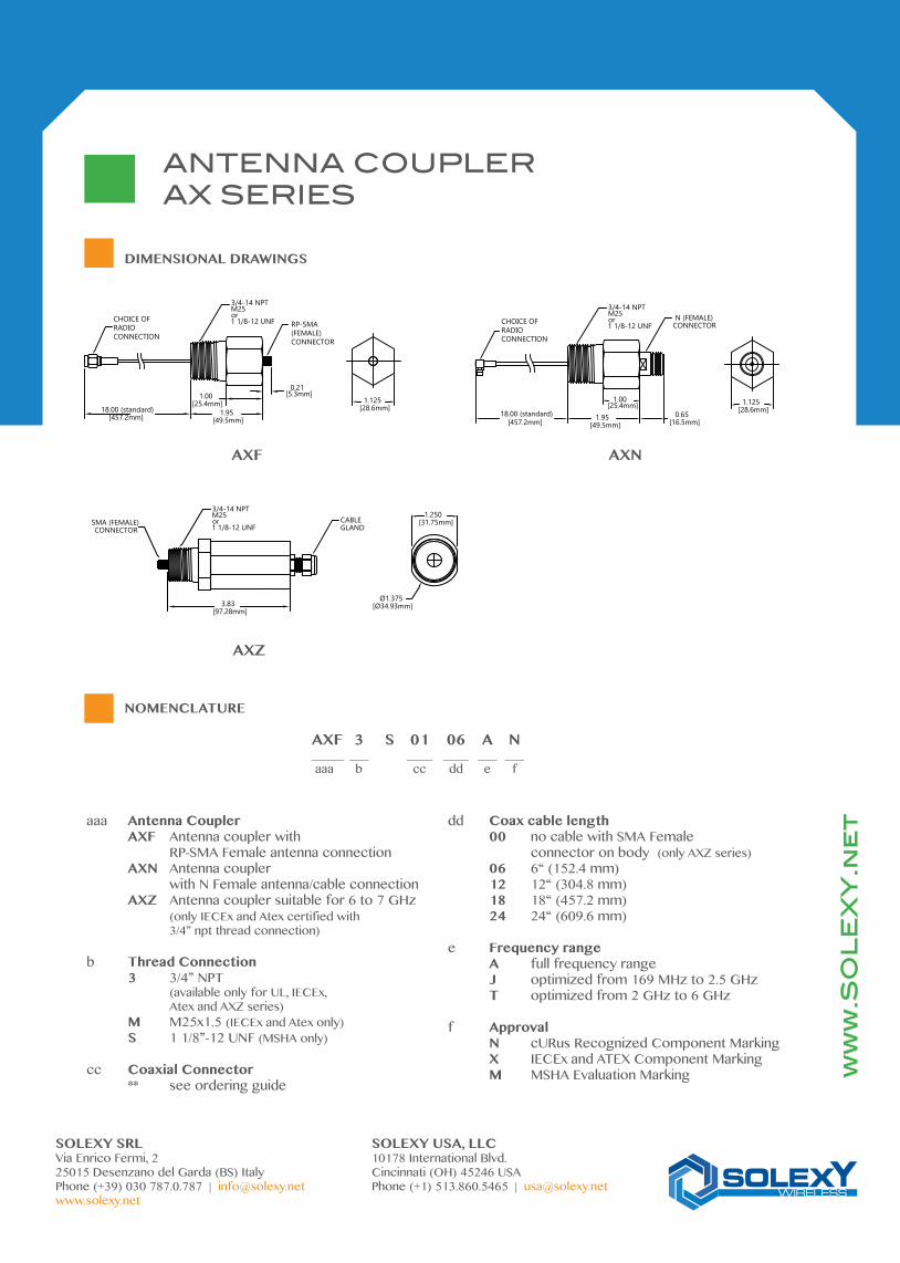
DIMENSIONAL DRAWINGS
NOMENCLATURE
ww
w.S
OL
EX
Y.n
et
SOLEXY SRL SOLEXY USA, LLCVia Enrico Fermi, 2 10178 International Blvd.25015 Desenzano del Garda (BS) Italy Cincinnati (OH) 45246 USAPhone (+39) 030 787.0.787 | [email protected] Phone (+1) 513.860.5465 | [email protected]
AXF 3 S 01 06 A N_____ ___ ____ ____ ___ ___ aaa b cc dd e f
aaa Antenna Coupler AXF Antenna coupler with RP-SMA Female antenna connection AXN Antenna coupler with N Female antenna/cable connection AXZ Antenna coupler suitable for 6 to 7 GHz (only IECEx and Atex certified with 3/4” npt thread connection)
b Thread Connection 3 3/4” NPT (available only for UL, IECEx, Atex and AXZ series) M M25x1.5 (IECEx and Atex only) S 1 1/8”-12 UNF (MSHA only)
cc Coaxial Connector ** see ordering guide
dd Coax cable length 00 no cable with SMA Female connector on body (only AXZ series) 06 6“ (152.4 mm) 12 12“ (304.8 mm) 18 18“ (457.2 mm) 24 24“ (609.6 mm)
e Frequency range A full frequency range J optimized from 169 MHz to 2.5 GHz T optimized from 2 GHz to 6 GHz
f Approval N cURus Recognized Component Marking X IECEx and ATEX Component Marking M MSHA Evaluation Marking
AXN
1.00[25.4mm]
1.95[49.5mm]
18.00 (standard)[457.2mm]
RP-SMA(FEMALE)CONNECTOR
0.21[5.3mm]
CHOICE OFRADIOCONNECTION
3/4-14 NPTM25or1 1/8-12 UNF
1.125[28.6mm]
3/4-14 NPTM25or1 1/8-12 UNF
1.00[25.4mm]
1.95[49.5mm]
1.125[28.6mm]0.65
[16.5mm]18.00 (standard)
[457.2mm]
CHOICE OFRADIOCONNECTION
N (FEMALE)CONNECTOR
AXZ
3/4-14 NPTM25or1 1/8-12 UNF
SMA (FEMALE) CONNECTOR
3.83[97.28mm]
1.250[31.75mm]
Ø1.375[Ø34.93mm]
CABLEGLAND
AXF
ANH72
Frequency Range 2.35 - 2.55 GHzImpedance (nominal) 50Ω @ 2.45 GHzVSWR (average) 1.13 : 1 (Average)Gain max 2.00 dBi
HEAVY DUTY ANTENNADIPOLE ANH SERIES
ww
w.S
OL
EX
Y.n
et
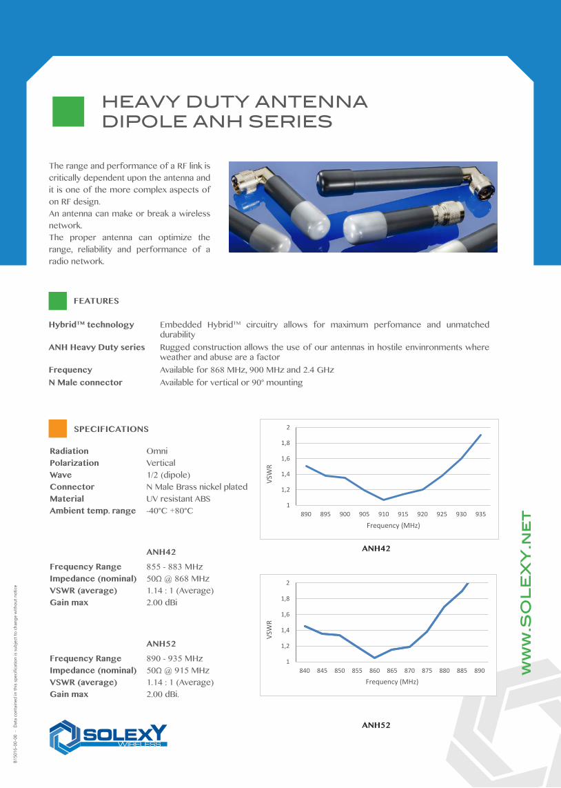
The range and performance of a RF link is critically dependent upon the antenna and it is one of the more complex aspects of on RF design. An antenna can make or break a wireless network.The proper antenna can optimize the range, reliability and performance of a radio network.
HybridTM technology Embedded HybridTM circuitry allows for maximum perfomance and unmatched durability
ANH Heavy Duty series Rugged construction allows the use of our antennas in hostile envinronments where weather and abuse are a factor
Frequency Available for 868 MHz, 900 MHz and 2.4 GHzN Male connector Available for vertical or 90° mounting
FEATURES
SPECIFICATIONS
B150
16-0
0-00
- D
ata
cont
aine
d in
this
spec
ifica
tion
is su
bjec
t to
chan
ge w
ithou
t not
ice
Radiation OmniPolarization VerticalWave 1/2 (dipole)Connector N Male Brass nickel platedMaterial UV resistant ABSAmbient temp. range -40°C +80°C
ANH42
Frequency Range 855 - 883 MHzImpedance (nominal) 50Ω @ 868 MHzVSWR (average) 1.14 : 1 (Average)Gain max 2.00 dBi
ANH52
Frequency Range 890 - 935 MHzImpedance (nominal) 50Ω @ 915 MHzVSWR (average) 1.14 : 1 (Average)Gain max 2.00 dBi.
ANH42
ANH52
1
1,2
1,4
1,6
1,8
2
890 895 900 905 910 915 920 925 930 935
VSW
R
Frequency (MHz)
1
1,2
1,4
1,6
1,8
2
840 845 850 855 860 865 870 875 880 885 890
VSW
R
Frequency (MHz)
ANH72
Frequency Range 2.35 - 2.55 GHzImpedance (nominal) 50Ω @ 2.45 GHzVSWR (average) 1.13 : 1 (Average)Gain max 2.00 dBi
HEAVY DUTY ANTENNADIPOLE ANH SERIES
ANH42-CNSUANH52-CNSUANH72-CNSU
0.93[23.62mm]
B
0.93[23.62mm]
1.60[40.64mm]
A
ANH42-CNRUANH52-CNRUANH72-CNRU
Model A inch [mm]
ANH42-CNSU 6.45 [158.20] ANH52-CNSU 6.45 [158.20] ANH72-CNSU 3.85 [97.80]
Model B inch [mm]
ANH42-CNRU 6.24 [158.50] ANH52-CNRU 6.24 [158.50] ANH72-CNRU 3.75 [95.25]
DIMENSIONAL DRAWING (inch)
a Frequency 4 868 MHz 5 900 MHz 7 2.4 GHz
b Antenna connection 3 N Female C N Male
c Antenna mounting S Straight (vertical) R Elbow (90°)
ANH 5 2 - C N S U
a b c
NOMENCLATURE
ANH72
1
1,2
1,4
1,6
1,8
2
2,35 2,4 2,45 2,5 2,55
VSW
R
Frequency (GHz)
ANH72
Frequency Range 2.35 - 2.55 GHzImpedance (nominal) 50Ω @ 2.45 GHzVSWR (average) 1.13 : 1 (Average)Gain max 2.00 dBi
ww
w.S
OL
EX
Y.n
et
SOLEXY SRL SOLEXY USA, LLCVia Enrico Fermi, 2 10178 International Blvd.25015 Desenzano del Garda (BS) Italy Cincinnati (OH) 45246 USAPhone (+39) 030 787.0.787 | [email protected] Phone (+1) 513.860.5465 | [email protected]
ANH72
Frequency Range 2.35 - 2.55 GHzImpedance (nominal) 50Ω @ 2.45 GHzVSWR (average) 1.13 : 1 (Average)Gain max 2.00 dBi
HEAVY DUTY ANTENNAJ-POLE ANH SERIES
ww
w.S
OL
EX
Y.n
et
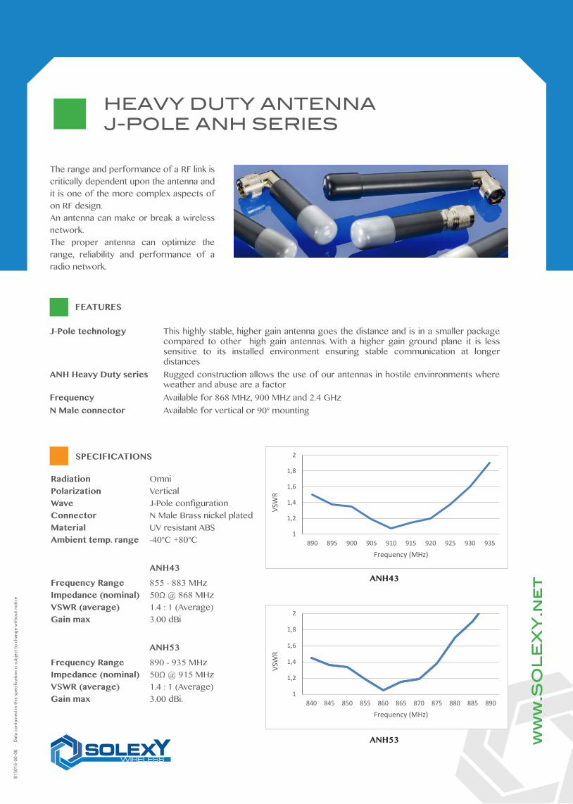
The range and performance of a RF link is critically dependent upon the antenna and it is one of the more complex aspects of on RF design. An antenna can make or break a wireless network.The proper antenna can optimize the range, reliability and performance of a radio network.
J-Pole technology This highly stable, higher gain antenna goes the distance and is in a smaller package compared to other high gain antennas. With a higher gain ground plane it is less sensitive to its installed environment ensuring stable communication at longer distances
ANH Heavy Duty series Rugged construction allows the use of our antennas in hostile envinronments where weather and abuse are a factor
Frequency Available for 868 MHz, 900 MHz and 2.4 GHzN Male connector Available for vertical or 90° mounting
FEATURES
SPECIFICATIONS
B150
16-0
0-00
- D
ata
cont
aine
d in
this
spec
ifica
tion
is su
bjec
t to
chan
ge w
ithou
t not
ice
Radiation OmniPolarization VerticalWave J-Pole configurationConnector N Male Brass nickel platedMaterial UV resistant ABSAmbient temp. range -40°C +80°C
ANH43
Frequency Range 855 - 883 MHzImpedance (nominal) 50Ω @ 868 MHzVSWR (average) 1.4 : 1 (Average)Gain max 3.00 dBi
ANH53
Frequency Range 890 - 935 MHzImpedance (nominal) 50Ω @ 915 MHzVSWR (average) 1.4 : 1 (Average)Gain max 3.00 dBi. 1
1,2
1,4
1,6
1,8
2
840 845 850 855 860 865 870 875 880 885 890
VSW
R
Frequency (MHz)
1
1,2
1,4
1,6
1,8
2
890 895 900 905 910 915 920 925 930 935
VSW
R
Frequency (MHz)
ANH43
ANH53
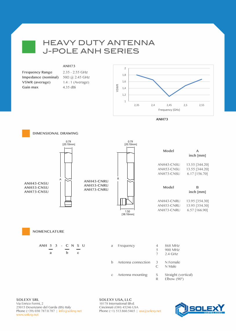
ANH73
Frequency Range 2.35 - 2.55 GHzImpedance (nominal) 50Ω @ 2.45 GHzVSWR (average) 1.4 : 1 (Average)Gain max 4.35 dBi
ANH72
Frequency Range 2.35 - 2.55 GHzImpedance (nominal) 50Ω @ 2.45 GHzVSWR (average) 1.13 : 1 (Average)Gain max 2.00 dBi
HEAVY DUTY ANTENNAJ-POLE ANH SERIES
ANH43-CNSUANH53-CNSUANH73-CNSU
0.79[20.10mm]
B
0.79[20.10mm]
1.50[38.10mm]
A ANH43-CNRUANH53-CNRUANH73-CNRU
Model A inch [mm]
ANH43-CNSU 13.55 [344.20] ANH53-CNSU 13.55 [344.20] ANH73-CNSU 6.17 [156.70]
Model B inch [mm]
ANH43-CNRU 13.95 [354.30] ANH53-CNRU 13.95 [354.30] ANH73-CNRU 6.57 [166.90]
DIMENSIONAL DRAWING
a Frequency 4 868 MHz 5 900 MHz 7 2.4 GHz
b Antenna connection 3 N Female C N Male
c Antenna mounting S Straight (vertical) R Elbow (90°)
ANH 5 3 - C N S U
a b c
NOMENCLATURE
1
1,2
1,4
1,6
1,8
2
2,35 2,4 2,45 2,5 2,55
VSW
R
Frequency (GHz)
ANH73
ANH73
Frequency Range 2.35 - 2.55 GHzImpedance (nominal) 50Ω @ 2.45 GHzVSWR (average) 1.4 : 1 (Average)Gain max 4.35 dBi
SOLEXY SRL SOLEXY USA, LLCVia Enrico Fermi, 2 10178 International Blvd.25015 Desenzano del Garda (BS) Italy Cincinnati (OH) 45246 USAPhone (+39) 030 787.0.787 | [email protected] Phone (+1) 513.860.5465 | [email protected]
ANH72
Frequency Range 2.35 - 2.55 GHzImpedance (nominal) 50Ω @ 2.45 GHzVSWR (average) 1.13 : 1 (Average)Gain max 2.00 dBi
FLEXIBLE HEAVY DUTY ANTENNAANF SERIES
ww
w.S
OL
EX
Y.n
et
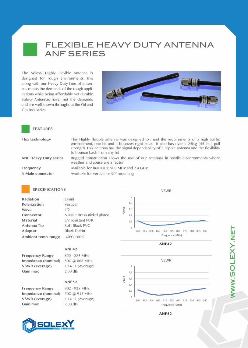
The Solexy Highly Flexible Antenna is designed for rough environments, this along with our Heavy Duty Line of anten-nas meets the demands of the tough appli-cations while being affordable yet durable.Solexy Antennas have met the demands and are well known throughout the Oil and Gas industries.
Flex technology This Highly flexible antenna was designed to meet the requirements of a high traffic environment, one hit and it bounces right back. It also has over a 25Kg (55 lbs.) pull strength. This antenna has the signal dependability of a Dipole antenna and the flexibility to bounce back from any hit
ANF Heavy Duty series Rugged construction allows the use of our antennas in hostile envinronments where weather and abuse are a factor.
Frequency Available for 868 MHz, 900 MHz and 2.4 GHzN Male connector Available for vertical or 90° mounting
FEATURES
SPECIFICATIONS
Radiation OmniPolarization VerticalWave 1/2Connector N Male Brass nickel platedMaterial UV resistant PURAntenna Tip Soft Black PVCAdapter Black DelrinAmbient temp. range -40°C +80°C
ANF42
Frequency Range 855 - 883 MHzImpedance (nominal) 50Ω @ 868 MHzVSWR (average) 1.14 : 1 (Average)Gain max 2.00 dBi
ANF52
Frequency Range 902 - 928 MHzImpedance (nominal) 50Ω @ 915 MHzVSWR (average) 1.14 : 1 (Average)Gain max 2.00 dBi
1
1,2
1,4
1,6
1,8
2
840 845 850 855 860 865 870 875 880 885 890
VSW
R
Frequency (MHz)
VSWR
1
1,2
1,4
1,6
1,8
2
890 895 900 905 910 915 920 925 930 935 940
VSW
R
Frequency (MHz)
VSWR
ANF42
ANF52
ANF72
Frequency Range 2.35 - 2.55 GHzImpedance (nominal) 50Ω @ 2.45 GHzVSWR (average) 1.14 : 1 (Average)Gain max 2.00 dBi
ANH72
Frequency Range 2.35 - 2.55 GHzImpedance (nominal) 50Ω @ 2.45 GHzVSWR (average) 1.13 : 1 (Average)Gain max 2.00 dBi
ANF52-CNSUANF42-CNSUANF72-CNSU
ANF52-CNRUANF42-CNRUANF72-CNRU
DIMENSIONAL DRAWING (inch)
a Frequency 4 868 MHz 5 900 MHz 7 2.4 GHz
b Antenna connection 3 N Female C N Male
b Antenna mounting S Straight (vertical) R Elbow (90°)
ANF 5 2 - C N S U
a b c
NOMENCLATURE
A
0.8[20.32mm]
1.13[28.70mm]
B
FLEXIBLE HEAVY DUTY ANTENNAANF SERIES
ANF72
Frequency Range 2.35 - 2.55 GHzImpedance (nominal) 50Ω @ 2.45 GHzVSWR (average) 1.14 : 1 (Average)Gain max 2.00 dBi
1
1,2
1,4
1,6
1,8
2
2,35 2,4 2,45 2,5 2,55
VSW
R
Frequency (GHz)
VSWR
Model A inch [mm]
ANF42-CNSU 11 [279.4] ANF52-CNSU 11 [279.4] ANF72-CNSU 7 [177.8]
Model B inch [mm]
ANF42-CNRU 11.4 [289.56] ANF52-CNRU 11.4 [289.56] ANF72-CNRU 7.4 [187.96]
ww
w.S
OL
EX
Y.n
et
SOLEXY SRL SOLEXY USA, LLCVia Enrico Fermi, 2 10178 International Blvd.25015 Desenzano del Garda (BS) Italy Cincinnati (OH) 45246 USAPhone (+39) 030 787.0.787 | [email protected] Phone (+1) 513.860.5465 | [email protected]
ANH72
Frequency Range 2.35 - 2.55 GHzImpedance (nominal) 50Ω @ 2.45 GHzVSWR (average) 1.13 : 1 (Average)Gain max 2.00 dBi
ww
w.S
OL
EX
Y.n
et
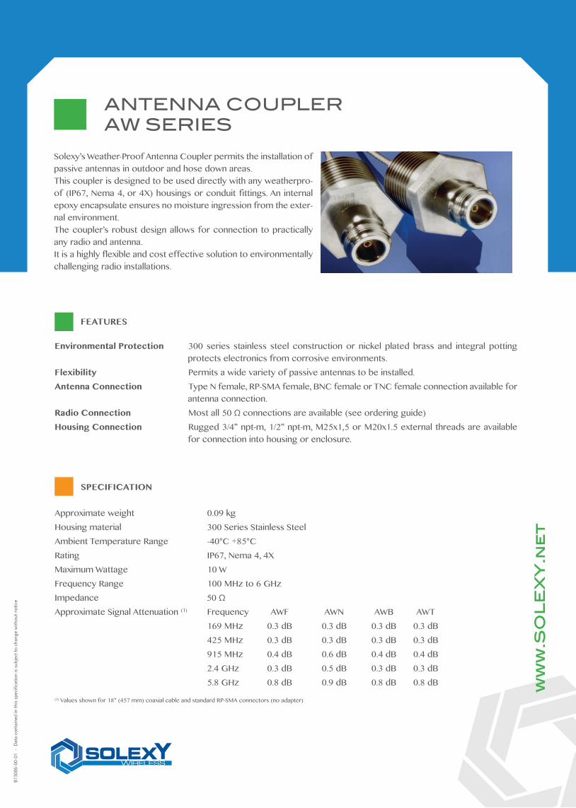
Solexy’s Weather-Proof Antenna Coupler permits the installation of passive antennas in outdoor and hose down areas.This coupler is designed to be used directly with any weatherpro-of (IP67, Nema 4, or 4X) housings or conduit fittings. An internal epoxy encapsulate ensures no moisture ingression from the exter-nal environment.The coupler’s robust design allows for connection to practically any radio and antenna.It is a highly flexible and cost effective solution to environmentally challenging radio installations.
Environmental Protection 300 series stainless steel construction or nickel plated brass and integral potting protects electronics from corrosive environments.
Flexibility Permits a wide variety of passive antennas to be installed.Antenna Connection Type N female, RP-SMA female, BNC female or TNC female connection available for
antenna connection.Radio Connection Most all 50 Ω connections are available (see ordering guide)Housing Connection Rugged 3/4” npt-m, 1/2” npt-m, M25x1,5 or M20x1.5 external threads are available
for connection into housing or enclosure.
FEATURES
SPECIFICATION
B130
06-0
0-01
- D
ata
cont
aine
d in
this
spec
ifica
tion
is su
bjec
t to
chan
ge w
ithou
t not
ice
ANTENNA COUPLERAW SERIES
Approximate weight 0.09 kgHousing material 300 Series Stainless SteelAmbient Temperature Range -40°C +85°CRating IP67, Nema 4, 4XMaximum Wattage 10 WFrequency Range 100 MHz to 6 GHzImpedance 50 ΩApproximate Signal Attenuation (1) Frequency AWF AWN AWB AWT 169 MHz 0.3 dB 0.3 dB 0.3 dB 0.3 dB 425 MHz 0.3 dB 0.3 dB 0.3 dB 0.3 dB 915 MHz 0.4 dB 0.6 dB 0.4 dB 0.4 dB 2.4 GHz 0.3 dB 0.5 dB 0.3 dB 0.3 dB 5.8 GHz 0.8 dB 0.9 dB 0.8 dB 0.8 dB
(2) Values shown for 18” (457 mm) coaxial cable and standard RP-SMA connectors (no adapter)
ANH72
Frequency Range 2.35 - 2.55 GHzImpedance (nominal) 50Ω @ 2.45 GHzVSWR (average) 1.13 : 1 (Average)Gain max 2.00 dBi
ANTENNA COUPLERAW SERIES
DIMENSIONAL DRAWING
NOMENCLATURE
ww
w.S
OL
EX
Y.n
et
SOLEXY SRL SOLEXY USA, LLCVia Enrico Fermi, 2 10178 International Blvd.25015 Desenzano del Garda (BS) Italy Cincinnati (OH) 45246 USAPhone (+39) 030 787.0.787 | [email protected] Phone (+1) 513.860.5465 | [email protected]
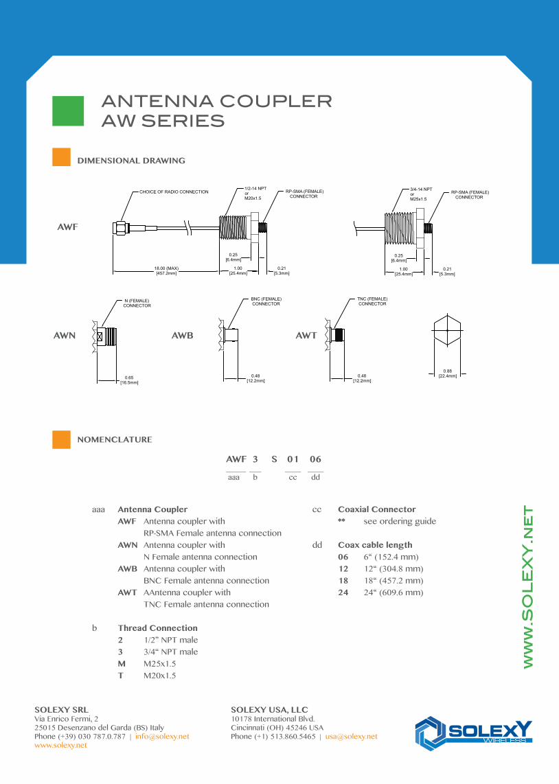
AWF 3 S 01 06_____ ___ ____ ____ aaa b cc dd
aaa Antenna Coupler AWF Antenna coupler with RP-SMA Female antenna connection AWN Antenna coupler with N Female antenna connection AWB Antenna coupler with BNC Female antenna connection AWT AAntenna coupler with TNC Female antenna connection
b Thread Connection 2 1/2” NPT male 3 3/4“ NPT male M M25x1.5 T M20x1.5
cc Coaxial Connector ** see ordering guide
dd Coax cable length 06 6“ (152.4 mm) 12 12“ (304.8 mm) 18 18“ (457.2 mm) 24 24“ (609.6 mm)
AWN AWB
AWF
3/4-14 NPTorM25x1.5
0.25[6.4mm]
1.00[25.4mm]
RP-SMA (FEMALE)CONNECTOR
0.21[5.3mm]
0.88[22.4mm]
1/2-14 NPTorM20x1.5
0.25[6.4mm]
1.00[25.4mm]
18.00 (MAX)[457.2mm]
CHOICE OF RADIO CONNECTION RP-SMA (FEMALE)CONNECTOR
0.21[5.3mm]
0.65[16.5mm]
N (FEMALE)CONNECTOR
0.48[12.2mm]
BNC (FEMALE) CONNECTOR
0.48[12.2mm]
TNC (FEMALE) CONNECTOR
AWT
ANH72
Frequency Range 2.35 - 2.55 GHzImpedance (nominal) 50Ω @ 2.45 GHzVSWR (average) 1.13 : 1 (Average)Gain max 2.00 dBi
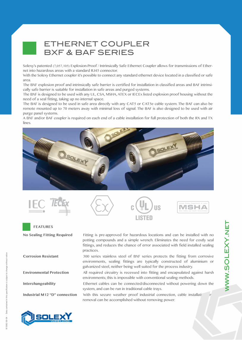
Solexy’s patented (7,057,105) Explosion-Proof / Intrinsically Safe Ethernet Coupler allows for transmissions of Ether-net into hazardous areas with a standard RJ45 connector.With the Solexy Ethernet coupler it’s possible to connect any standard ethernet device located in a classified or safe area.The BXF explosion proof and intrinsically safe barrier is certified for installation in classified areas and BAF intrinsi-cally safe barrier is suitable for installation in safe areas and purged systems.The BXF is designed to be used with any UL, CSA, MSHA, ATEX or IECEx listed explosion proof housing without the need of a seal fitting, taking up no internal space. The BAF is designed to be used in safe area directly with any CAT5 or CAT5e cable system. The BAF can also be remote mounted up to 70 meters away with minimal loss of signal. The BAF is also designed to be used with air purge panel systems.A BXF and/or BAF coupler is required on each end of a cable installation for full protection of both the RX and TX lines.
No Sealing Fitting Required Fitting is pre-approved for hazardous locations and can be installed with no potting compounds and a simple wrench. Eliminates the need for costly seal fittings, and reduces the chance of error associated with field installed sealing practices.
Corrosion Resistant 300 series stainless steel of BXF series protects the fitting from corrosive environments, sealing fittings are typically constructed of aluminium or galvanized steel, neither being well suited for the process industry.
Environmental Protection All required circuitry is recessed into fitting and encapsulated against harsh environments; this is impossible with conventional sealing methods.
Interchangeability Ethernet cables can be connected/disconnected without powering down the system, and can be run in traditional cable trays.
Industrial M12 “D” connection With this secure weather proof industrial connection, cable installation and removal can be accomplished without removing power.
ww
w.S
OL
EX
Y.n
et
FEATURES
B130
02-0
0-04
- D
ata
cont
aine
d in
this
spec
ifica
tion
is su
bjec
t to
chan
ge w
ithou
t not
ice
ETHERNET COUPLERBXF & BAF SERIES
ANH72
Frequency Range 2.35 - 2.55 GHzImpedance (nominal) 50Ω @ 2.45 GHzVSWR (average) 1.13 : 1 (Average)Gain max 2.00 dBi
IECEx / ATEX Certification:
BAF I (M1) [Ex ia Ma] I BXF3S & BXFMS I M2 (M1) Ex d mb [ia Ma] I Mb II (1) G [Ex ia Ga] IIC II 2 (1) G Ex d mb [ia Ga] IIC T5 Gb II (1) D [Ex ia Da] IIIC II 2 (1) D Ex mb [ia Da] IIIC T100°C Db
ATEX certificate nr. DNV 14 ATEX 4192XIECEx certificate nr. IECEx DNV 14.0024X
CULUS Certification:
BAF3S & BXF3S Class I, Group A,B,C,D, Class II, Group F,G (UL File nr. E305231)
Maximum Fault Voltage RMS 250 VCurrent Protection 50 mAFrequency Range up to 100 MHzInsertion loss -5.5 dBTotal impedance < 100 OhmProtection 3.6 VAmbient Temperature Range -20°C +60°CEthernet connection IEEE 802.3 - 100BaseTX - 100 MbpsData connector (hazardous side) M12 Industrial “D” coded connectorHousing Material BXF = 300 SST (approximate weight 0.38 kg) BAF = T6 Aluminum nickel plated (approximate weight 0.2 kg)
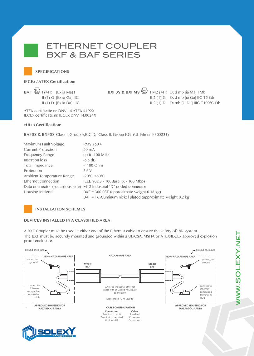
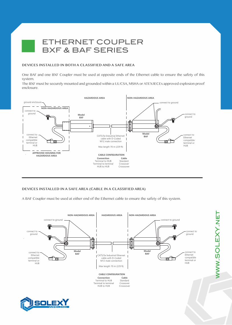
DEVICES INSTALLED IN A CLASSIFIED AREA
A BXF Coupler must be used at either end of the Ethernet cable to ensure the safety of this system.The BXF must be securely mounted and grounded within a UL/CSA, MSHA or ATEX/IECEx approved explosion proof enclosure.
CABLE CONFIGURATION Connection Cable Terminal to HUB Standard Terminal to terminal Crossover HUB to HUB Crosssover
CAT5/5e Industrial Ethernetcable with D-Coded M12 male
connection
Max length 70 m (229 ft)
ModelBXF
ModelBXF
ground enclosure
connect toground
connect toEthernet
compatible terminal or
HUB
HAZARDOUS AREANON-HAZARDOUS AREA
APPROVED HOUSING FORHAZARDOUS AREA
APPROVED HOUSING FORHAZARDOUS AREA
connect toground
connect toEthernetcompatible terminal or HUB
ground enclosure
NON-HAZARDOUS AREA
ww
w.S
OL
EX
Y.n
et
SPECIFICATIONS
ETHERNET COUPLERBXF & BAF SERIES
INSTALLATION SCHEMES
ANH72
Frequency Range 2.35 - 2.55 GHzImpedance (nominal) 50Ω @ 2.45 GHzVSWR (average) 1.13 : 1 (Average)Gain max 2.00 dBi
CABLE CONFIGURATION Connection Cable Terminal to HUB Standard Terminal to terminal Crossover HUB to HUB Crosssover
CAT5/5e Industrial Ethernetcable with D-Coded
M12 male connection
Max length 70 m (229 ft)
ModelBAF
ModelBAF
connect toground
connect toEthernet
compatible terminal or
HUB
NON-HAZARDOUS AREA
connect toEthernetcompatible terminal or HUB
HAZARDOUS AREA NON-HAZARDOUS AREA
connect toground
connect to groundconnect to ground
DEVICES INSTALLED IN A SAFE AREA (CABLE IN A CLASSIFIED AREA)
A BAF Coupler must be used at either end of the Ethernet cable to ensure the safety of this system.
CABLE CONFIGURATION Connection Cable Terminal to HUB Standard Terminal to terminal Crossover HUB to HUB Crosssover
CAT5/5e Industrial Ethernetcable with D-Coded
M12 male connection
Max length 70 m (229 ft)
ModelBXF
ground enclosure
connect toground
connect toEthernet
compatible terminal or
HUB
NON-HAZARDOUS AREA
APPROVED HOUSING FORHAZARDOUS AREA
ModelBAF
connect toEthernetcompatible terminal or HUB
NON-HAZARDOUS AREA
connect toground
connect to ground
HAZARDOUS AREA
DEVICES INSTALLED IN BOTH A CLASSIFIED AND A SAFE AREA
One BAF and one BXF Coupler must be used at opposite ends of the Ethernet cable to ensure the safety of this system.The BXF must be securely mounted and grounded within a UL/CSA, MSHA or ATEX/IECEx approved explosion proof enclosure.
ww
w.S
OL
EX
Y.n
et
ETHERNET COUPLERBXF & BAF SERIES
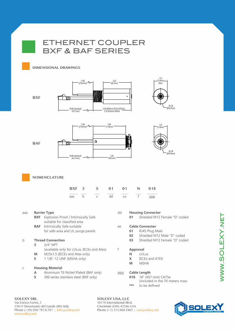
BXF 3 S 01 01 N 018_____ ___ ___ ____ ____ ___ ______aaa b c dd ee f ggg
2.63[66.7mm]
3.58 [90.8mm] IECEx/ATEX/UL3.70 [94.0mm] MSHA
1.25[31.8mm]
(flats)11.00
[279.4mm]
18.00 (standard)[457.2mm]
Ø1.38[Ø34.9mm]
11.00[279.4mm]
18.00 (standard)[457.2mm]
3.56[90.5mm]
3.06[77.8mm]
1.25[31.8mm]
Ø1.38[Ø34.9mm]
BXF
BAF
ETHERNET COUPLERBXF & BAF SERIES
DIMENSIONAL DRAWINGS
NOMENCLATURE
ww
w.S
OL
EX
Y.n
et
SOLEXY SRL SOLEXY USA, LLCVia Enrico Fermi, 2 10178 International Blvd.25015 Desenzano del Garda (BS) Italy Cincinnati (OH) 45246 USAPhone (+39) 030 787.0.787 | [email protected] Phone (+1) 513.860.5465 | [email protected]
aaa Barrier Type BXF Explosion Proof / Intrinsically Safe suitable for classified area BAF Intrinsically Safe suitable for safe area and UL purge panels
b Thread Connection 3 3/4” NPT (available only for cULus, IECEx and Atex) M M25x1.5 (IECEx and Atex only) S 1 1/8”-12 UNF (MSHA only)
c Housing Material A Aluminum T6 Nickel Plated (BAF only) S 300 series stainless steel (BXF only)
dd Housing Connector 01 Shielded M12 Female “D” coded
ee Cable Connector 01 RJ45 Plug Male 02 Shielded M12 Male “D” coded 03 Shielded M12 Female “D” coded
f Approval N cULus X IECEx and ATEX M MSHA
ggg Cable Length 018 18” (457 mm) CAT5e (included in the 70 meters max) *** to be defined
UL version ATEX IECEx version
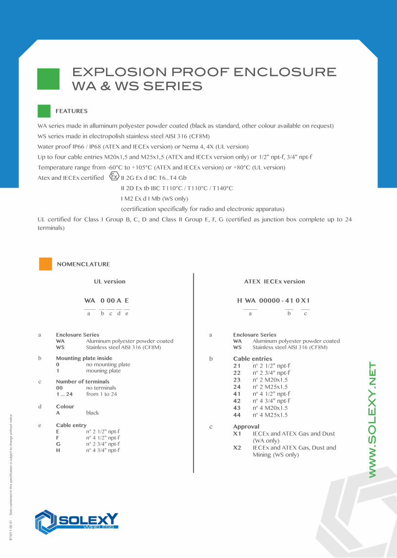
WA 0 00 A E____ __ ___ __ __ a b c d e
a Enclosure Series WA Aluminum polyester powder coated WS Stainless steel AISI 316 (CF8M)
b Mounting plate inside 0 no mounting plate 1 mouning plate
c Number of terminals 00 no terminals 1 ... 24 from 1 to 24
d Colour A black
e Cable entry E n° 2 1/2” npt-f F n° 4 1/2” npt-f G n° 2 3/4” npt-f H n° 4 3/4” npt-f
WA series made in alluminum polyester powder coated (black as standard, other colour available on request)
WS series made in electropolish stainless steel AISI 316 (CF8M)
Water proof IP66 / IP68 (ATEX and IECEx version) or Nema 4, 4X (UL version)
Up to four cable entries M20x1,5 and M25x1,5 (ATEX and IECEx version only) or 1/2” npt-f, 3/4” npt-f
Temperature range from -60°C to +105°C (ATEX and IECEx version) or +80°C (UL version)
Atex and IECEx certified II 2G Ex d IIC T6...T4 Gb
II 2D Ex tb IIIC T110°C / T110°C / T140°C
I M2 Ex d I Mb (WS only)
(certification specifically for radio and electronic apparatus)
UL certified for Class I Group B, C, D and Class II Group E, F, G (certified as junction box complete up to 24 terminals)
H WA 00000 - 41 0 X1 _____ ___ ___ a b c
a Enclosure Series WA Aluminum polyester powder coated WS Stainless steel AISI 316 (CF8M)
b Cable entries 21 n° 2 1/2” npt-f 22 n° 2 3/4“ npt-f 23 n° 2 M20x1.5 24 n° 2 M25x1.5 41 n° 4 1/2” npt-f 42 n° 4 3/4” npt-f 43 n° 4 M20x1.5 44 n° 4 M25x1.5
c Approval X1 IECEx and ATEX Gas and Dust (WA only) X2 IECEx and ATEX Gas, Dust and Mining (WS only)
ww
w.S
OL
EX
Y.n
et
FEATURES
B150
11-0
0-01
- D
ata
cont
aine
d in
this
spec
ifica
tion
is su
bjec
t to
chan
ge w
ithou
t not
ice
EXPLOSION PROOF ENCLOSUREWA & WS SERIES
NOMENCLATURE
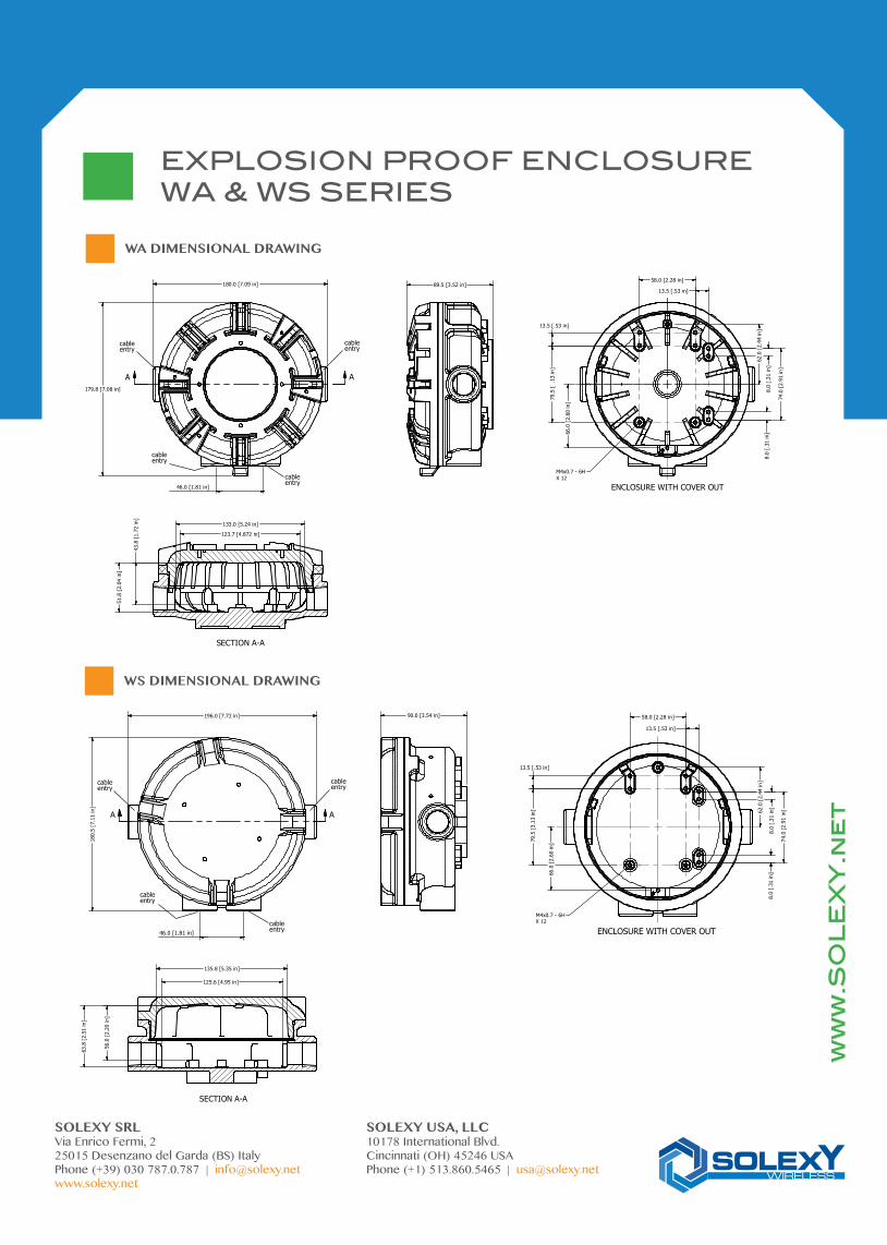
SECTION A-A
A A
89.5 [3.52 in]
51.8
[2.
04 in
]
43.8
[1.7
2 in
]
123.7 [4.872 in]
133.0 [5.24 in]
180.0 [7.09 in]
179.8 [7.08 in]
58.0 [2.28 in]
74.0
[2.9
1 in
]
79.5
[ 3.13
in]
8.0
[.31
in]
8.0
[.31
in]
13.5 [.53 in]
13.5 [.53 in]
62.0
[2.4
4 in
]
66.0
[2.
60 in
]
M4x0.7 - 6HX 12
46.0 [1.81 in] ENCLOSURE WITH COVER OUT
cableentry
cableentry
cableentry
cableentry
SECTION A-A
A A
90.0 [3.54 in]196.0 [7.72 in]
180.
5 [7
.11
in]
56.0
[2.2
0 in
]
63.8
[2.
51 in
]
125.6 [4.95 in]
135.8 [5.35 in]
79.5
[3.1
3 in
]
13.5 [.53 in]
66.0
[2.6
0 in
]
58.0 [2.28 in]
13.5 [.53 in]
62.0
[2.
44 in
]
74.0
[2.9
1 in
]
M4x0.7 - 6HX 12
8.0
[.31
in]
8.0
[.31
in]
ENCLOSURE WITH COVER OUT46.0 [1.81 in]
cableentrycable
entry
cableentry
cableentry
EXPLOSION PROOF ENCLOSUREWA & WS SERIES
ww
w.S
OL
EX
Y.n
et
SOLEXY SRL SOLEXY USA, LLCVia Enrico Fermi, 2 10178 International Blvd.25015 Desenzano del Garda (BS) Italy Cincinnati (OH) 45246 USAPhone (+39) 030 787.0.787 | [email protected] Phone (+1) 513.860.5465 | [email protected]
WA DIMENSIONAL DRAWING
WS DIMENSIONAL DRAWING
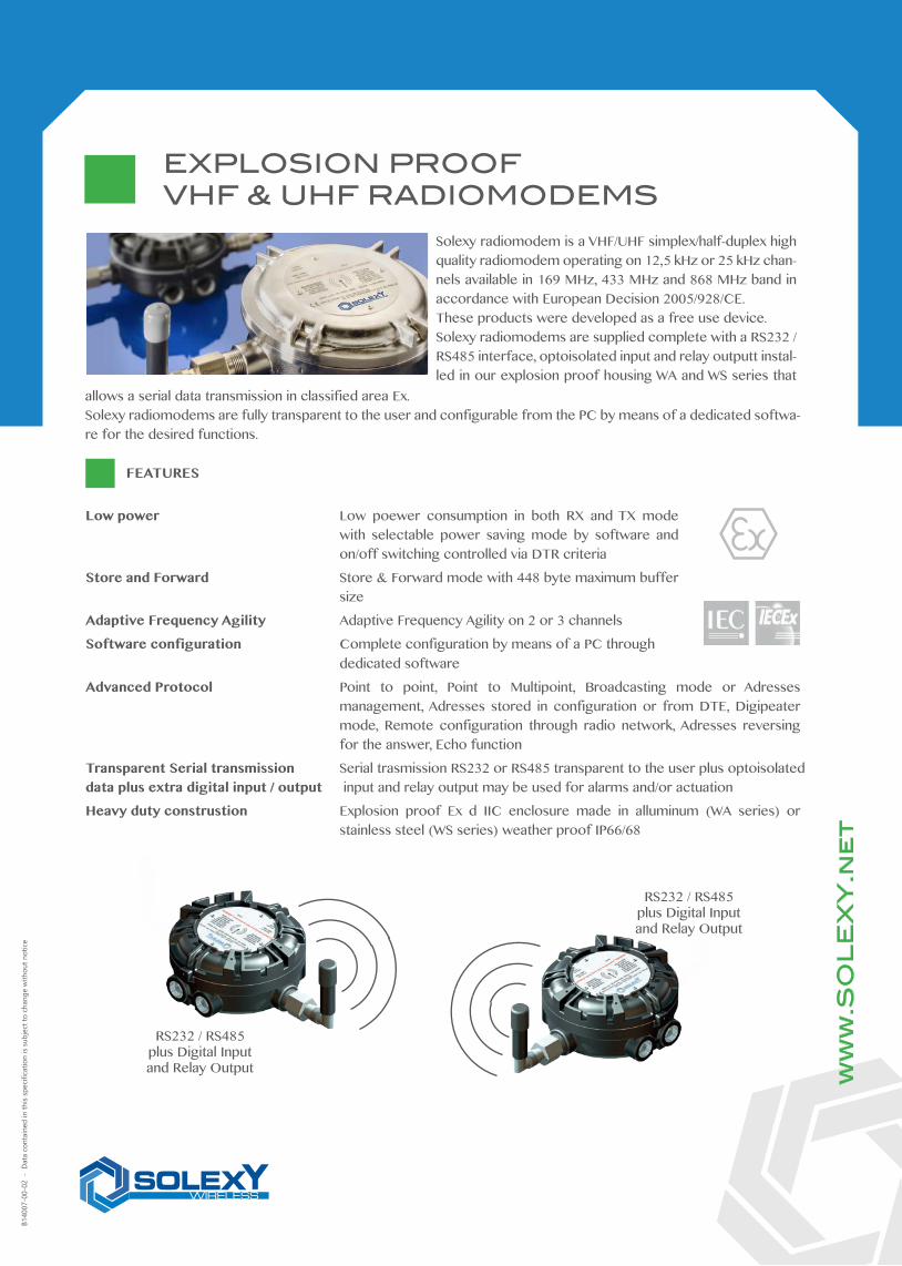
Low power Low poewer consumption in both RX and TX mode with selectable power saving mode by software and on/off switching controlled via DTR criteria
Store and Forward Store & Forward mode with 448 byte maximum buffer size
Adaptive Frequency Agility Adaptive Frequency Agility on 2 or 3 channels
Software configuration Complete configuration by means of a PC through dedicated software
Advanced Protocol Point to point, Point to Multipoint, Broadcasting mode or Adresses management, Adresses stored in configuration or from DTE, Digipeater mode, Remote configuration through radio network, Adresses reversing for the answer, Echo function
Transparent Serial transmission Serial trasmission RS232 or RS485 transparent to the user plus optoisolateddata plus extra digital input / output input and relay output may be used for alarms and/or actuation
Heavy duty construstion Explosion proof Ex d IIC enclosure made in alluminum (WA series) or stainless steel (WS series) weather proof IP66/68
Solexy radiomodem is a VHF/UHF simplex/half-duplex high quality radiomodem operating on 12,5 kHz or 25 kHz chan-nels available in 169 MHz, 433 MHz and 868 MHz band in accordance with European Decision 2005/928/CE.These products were developed as a free use device.Solexy radiomodems are supplied complete with a RS232 / RS485 interface, optoisolated input and relay outputt instal-led in our explosion proof housing WA and WS series that
allows a serial data transmission in classified area Ex.Solexy radiomodems are fully transparent to the user and configurable from the PC by means of a dedicated softwa-re for the desired functions.
RS232 / RS485plus Digital Input and Relay Output
RS232 / RS485plus Digital Input and Relay Output
ww
w.S
OL
EX
Y.n
et
FEATURES
B140
07-0
0-02
- D
ata
cont
aine
d in
this
spec
ifica
tion
is su
bjec
t to
chan
ge w
ithou
t not
ice
EXPLOSION PROOFVHF & UHF RADIOMODEMS
SPECIFICATIONS
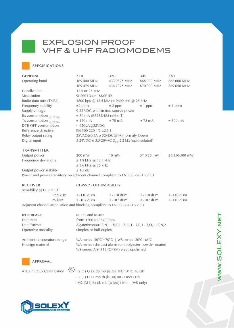
GENERAL 310 320 340 341Operating band 169.400 MHz 433.0875 MHz 868.000 MHz 868.000 MHz 169.475 MHz 434.7375 MHz 870.000 MHz 869.650 MHzCanalization 12.5 or 25 kHzModulation 9K00F1D or 18K0F1DRadio data rate (Tx/Rx) 4800 bps @ 12.5 kHz or 9600 bps @ 25 kHz Frequency stability ±2 ppm ± 2 ppm ± 1 ppm ± 1 ppmSupply voltage 9-32 VDC with limited source powerRx consumption (@12 VDC) ≈ 30 mA (RS232/485 relè off)Tx consumption (@12 VDC) ≈ 170 mA ≈ 70 mA ≈ 75 mA ≈ 300 mADTR OFF consumption < 920µA@32VDCReference directive EN 300 220-1/2 v.2.3.1Relay output rating [email protected] o 32VDC@1A (normaly Open)Digital input 5-24VDC o 3.5-20VAC ZINP 2.2 kΩ (optoisolated)
TRANSMITTEROutput power 200 mW 10 mW 5/10/25 mW 25/150/500 mWFrequency deviations ± 1.8 kHz @ 12.5 kHz ± 3.6 kHz @ 25 kHzOutput power stability ± 1.5 dBPower and power transitory on adjacent channel compliant to EN 300 220-1 v.2.3.1
RECEIVER CLASS 2 - LBT and AGILITYSensibility @ BER < 10-2 12.5 kHz < -110 dBm < -110 dBm < -110 dBm < -110 dBm 25 kHz < -107 dBm < -107 dBm < -107 dBm < -110 dBmAdjacent channel attenuation and blocking compliant to EN 300 220-1 v.2.3.1
INTERFACE RS232 and RS485Data rate from 1200 to 38400 bpsData format Asyncrhronous 8,N,1 - 8,E,1 - 8,O,1 - 7,E,1 - 7,O,1 - T,N,2Operative modality Simplex or half-duplex
Ambient temperature range WA series -30°C +70°C | WS series -30°C +65°CHousign material WA series : die cast aluminium polyester powder coated WS series: AISI 316 (CF8M) electropolished
ATEX / IECEx Certification II 2 (1) G Ex db mb [ia Ga] IIA/IIB/IIC T6 Gb II 2 (1) D Ex mb tb [ia Da] IIIC T85°C Db I M2 (M1) Ex db mb [ia Ma] I Mb (WS only)
ww
w.S
OL
EX
Y.n
et
EXPLOSION PROOFVHF & UHF RADIOMODEMS
APPROVAL
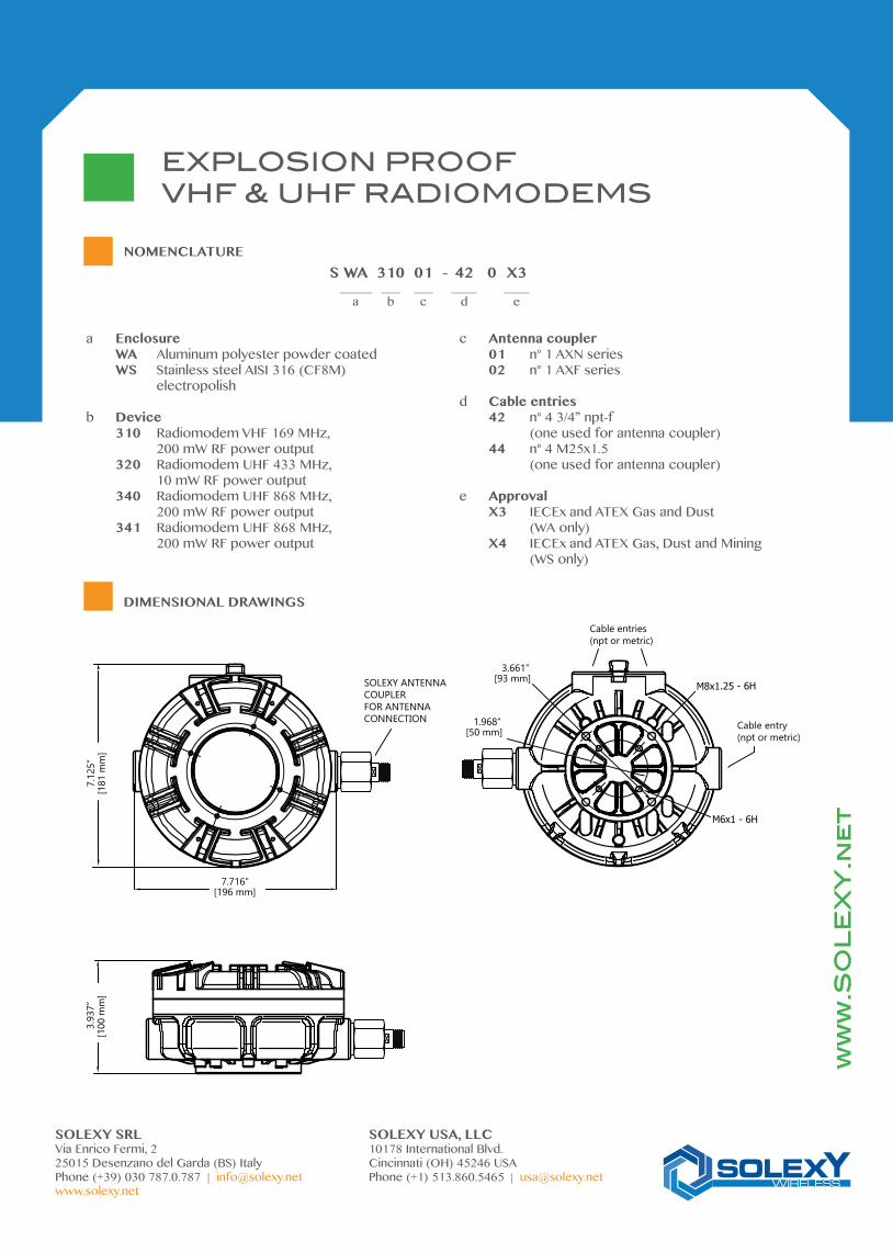
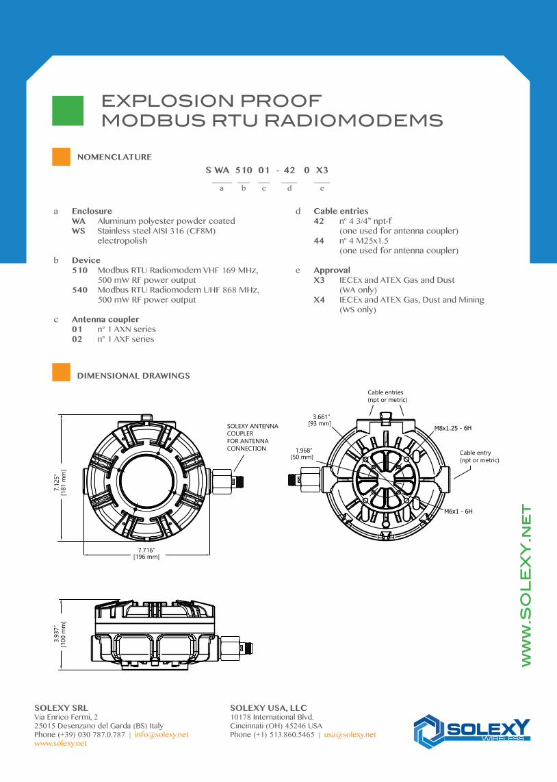
SOLEXY ANTENNACOUPLER FOR ANTENNACONNECTION
7.716”[196 mm]
7.12
5”[1
81 m
m]
3.93
7”[1
00 m
m]
Cable entries(npt or metric)
M8x1.25 - 6H
M6x1 - 6H
1.968”[50 mm]
3.661”[93 mm]
Cable entry(npt or metric)
EXPLOSION PROOFVHF & UHF RADIOMODEMS
DIMENSIONAL DRAWINGS
ww
w.S
OL
EX
Y.n
et
SOLEXY SRL SOLEXY USA, LLCVia Enrico Fermi, 2 10178 International Blvd.25015 Desenzano del Garda (BS) Italy Cincinnati (OH) 45246 USAPhone (+39) 030 787.0.787 | [email protected] Phone (+1) 513.860.5465 | [email protected]
NOMENCLATURES WA 310 01 - 42 0 X3 _____ ___ ___ ____ ____ a b c d e
a Enclosure WA Aluminum polyester powder coated WS Stainless steel AISI 316 (CF8M) electropolish
b Device 310 Radiomodem VHF 169 MHz, 200 mW RF power output 320 Radiomodem UHF 433 MHz, 10 mW RF power output 340 Radiomodem UHF 868 MHz, 200 mW RF power output 341 Radiomodem UHF 868 MHz, 200 mW RF power output
c Antenna coupler 01 n° 1 AXN series 02 n° 1 AXF series
d Cable entries 42 n° 4 3/4” npt-f (one used for antenna coupler) 44 n° 4 M25x1.5 (one used for antenna coupler)
e Approval X3 IECEx and ATEX Gas and Dust (WA only) X4 IECEx and ATEX Gas, Dust and Mining (WS only)

The Solexy MODBUS RTU radiomodem is a VHF/UHF high quality 500 mW radiomodem operating on 12,5 / 25 kHz channels available in 169 MHz and 868 MHz band in accor-ding to European Decision 2005/928/CE.These products are develop in order to be a free use device.The Solexy MODBUS RTU radiomodems are supply complete with 4 digital input, 2 digital output plus 2 analog input and 2 analog output 4-20 mA that allows to has an Modbus RTU nodle. The RS485 interface permit also the connection up to 4 Modbus module.The WA and WS anclosure thanks to its rugged construction combined to Atex and IECEx certificate achieves to have an Modbus RTU data transmission in classified area Ex.
Modbus
4 digital IN2 digital OUT
2 analog IN 4-20 mA2 analog OUT 4-20 mA
RS485 Modbus RTU port
4 digital IN2 digital OUT
2 analog IN 4-20 mA2 analog OUT 4-20 mA
RS485 Modbus RTU port
ww
w.S
OL
EX
Y.n
et
FEATURES
B140
08-0
0-02
- D
ata
cont
aine
d in
this
spec
ifica
tion
is su
bjec
t to
chan
ge w
ithou
t not
ice
EXPLOSION PROOFMODBUS RTU RADIOMODEMS
Modbus RTU The Solexy MODBUS RTU radiomodem can be used on all Modbus RTU application
Wide range of transmission option Mirror (point to point), Modbus RTU, Modbus multi master and standard Radiomodem option completely transparent to the user also in case of complex route
Modbus RTU Nodle 4 PNP digital input combinet to 2 relay output plus 2 analg input and 2 optoisolated analog output 4-20 mA allows to use the radiomodem as a complete Modbus RTU nodle.
Low power Low power consumption in both RX and TX mode and bistable relay on digital output allows the Solexy radiomodem suitable to battery operation
Adaptive Frequency Agility Adaptive Frequency Agility on 2 or 3 channels
Software configuration Complete configuration by PC through dedicated software
Encryption transmission data Secure transmission data thanks to AES (Advanced Encryption Standard) at 128 bit
Heavy duty construstion Explosion proof Ex d IIC enclosure made in alluminum (WA series) or stainless steel (WS series) weather proof IP66/68
SPECIFICATIONS
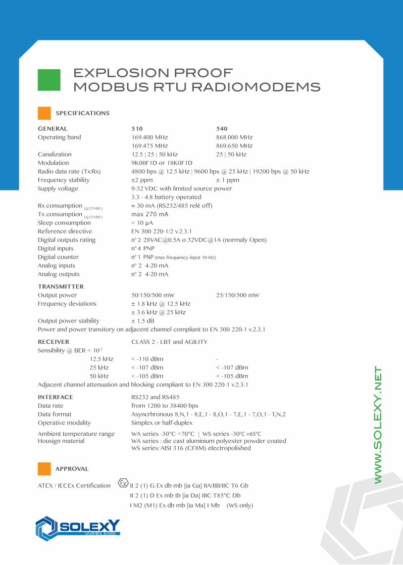
ATEX / IECEx Certification II 2 (1) G Ex db mb [ia Ga] IIA/IIB/IIC T6 Gb II 2 (1) D Ex mb tb [ia Da] IIIC T85°C Db I M2 (M1) Ex db mb [ia Ma] I Mb (WS only)
ww
w.S
OL
EX
Y.n
et
EXPLOSION PROOFMODBUS RTU RADIOMODEMS
APPROVAL
GENERAL 510 540Operating band 169.400 MHz 868.000 MHz 169.475 MHz 869.650 MHzCanalization 12.5 | 25 | 50 kHz 25 | 50 kHzModulation 9K00F1D or 18K0F1DRadio data rate (Tx/Rx) 4800 bps @ 12.5 kHz | 9600 bps @ 25 kHz | 19200 bps @ 50 kHzFrequency stability ±2 ppm ± 1 ppmSupply voltage 9-32 VDC with limited source power 3.3 - 4.8 battery operatedRx consumption (@12 VDC) ≈ 30 mA (RS232/485 relè off)Tx consumption (@12 VDC) max 270 mA
Sleep consumption < 10 µAReference directive EN 300 220-1/2 v.2.3.1Digital outputs rating n° 2 [email protected] o 32VDC@1A (normaly Open)Digital inputs n° 4 PNP Digital counter n° 1 PNP (max frequency input 10 Hz)
Analog inputs n° 2 4-20 mAAnalog outputs n° 2 4-20 mA
TRANSMITTEROutput power 50/150/500 mW 25/150/500 mWFrequency deviations ± 1.8 kHz @ 12.5 kHz ± 3.6 kHz @ 25 kHzOutput power stability ± 1.5 dBPower and power transitory on adjacent channel compliant to EN 300 220-1 v.2.3.1
RECEIVER CLASS 2 - LBT and AGILITYSensibility @ BER < 10-2 12.5 kHz < -110 dBm - 25 kHz < -107 dBm < -107 dBm 50 kHz < -105 dBm < -105 dBmAdjacent channel attenuation and blocking compliant to EN 300 220-1 v.2.3.1
INTERFACE RS232 and RS485Data rate from 1200 to 38400 bpsData format Asyncrhronous 8,N,1 - 8,E,1 - 8,O,1 - 7,E,1 - 7,O,1 - T,N,2Operative modality Simplex or half-duplex
Ambient temperature range WA series -30°C +70°C | WS series -30°C +65°CHousign material WA series : die cast aluminium polyester powder coated WS series: AISI 316 (CF8M) electropolished
SOLEXY ANTENNACOUPLER FOR ANTENNACONNECTION
7.716”[196 mm]
7.12
5”[1
81 m
m]
3.93
7”[1
00 m
m]
Cable entries(npt or metric)
M8x1.25 - 6H
M6x1 - 6H
1.968”[50 mm]
3.661”[93 mm]
Cable entry(npt or metric)
EXPLOSION PROOFMODBUS RTU RADIOMODEMS
DIMENSIONAL DRAWINGS
ww
w.S
OL
EX
Y.n
et
SOLEXY SRL SOLEXY USA, LLCVia Enrico Fermi, 2 10178 International Blvd.25015 Desenzano del Garda (BS) Italy Cincinnati (OH) 45246 USAPhone (+39) 030 787.0.787 | [email protected] Phone (+1) 513.860.5465 | [email protected]
NOMENCLATURES WA 510 01 - 42 0 X3 _____ ___ ___ ____ ____ a b c d e
a Enclosure WA Aluminum polyester powder coated WS Stainless steel AISI 316 (CF8M) electropolish
b Device 510 Modbus RTU Radiomodem VHF 169 MHz, 500 mW RF power output 540 Modbus RTU Radiomodem UHF 868 MHz, 500 mW RF power output
c Antenna coupler 01 n° 1 AXN series 02 n° 1 AXF series
d Cable entries 42 n° 4 3/4” npt-f (one used for antenna coupler) 44 n° 4 M25x1.5 (one used for antenna coupler)
e Approval X3 IECEx and ATEX Gas and Dust (WA only) X4 IECEx and ATEX Gas, Dust and Mining (WS only)
WiFi3G/LTE/HSPA+
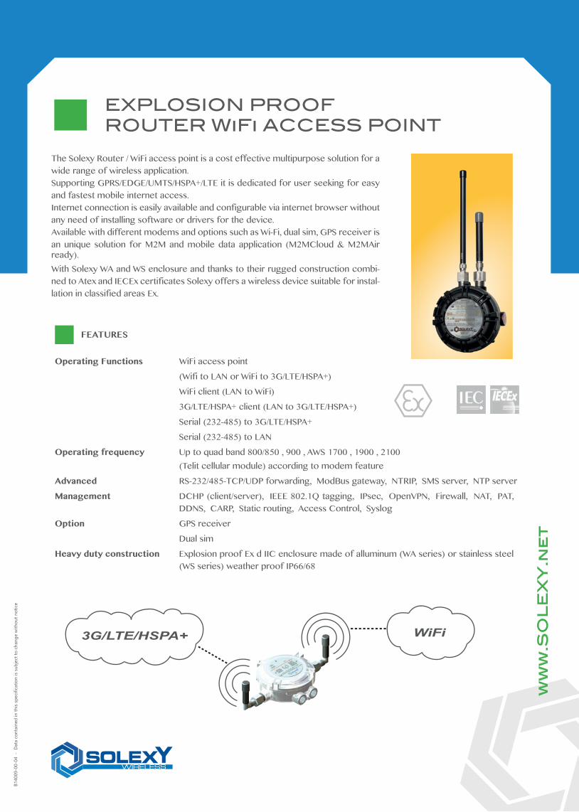
The Solexy Router / WiFi access point is a cost effective multipurpose solution for a wide range of wireless application.Supporting GPRS/EDGE/UMTS/HSPA+/LTE it is dedicated for user seeking for easy and fastest mobile internet access.Internet connection is easily available and configurable via internet browser without any need of installing software or drivers for the device.Available with different modems and options such as Wi-Fi, dual sim, GPS receiver is an unique solution for M2M and mobile data application (M2MCloud & M2MAir ready).With Solexy WA and WS enclosure and thanks to their rugged construction combi-ned to Atex and IECEx certificates Solexy offers a wireless device suitable for instal-lation in classified areas Ex.
ww
w.S
OL
EX
Y.n
et
FEATURES
B140
09-0
0-04
- D
ata
cont
aine
d in
this
spec
ifica
tion
is su
bjec
t to
chan
ge w
ithou
t not
ice
EXPLOSION PROOFROUTER WiFi ACCESS POINT
Operating Functions WiFi access point
(Wifi to LAN or WiFi to 3G/LTE/HSPA+)
WiFi client (LAN to WiFi)
3G/LTE/HSPA+ client (LAN to 3G/LTE/HSPA+)
Serial (232-485) to 3G/LTE/HSPA+
Serial (232-485) to LAN
Operating frequency Up to quad band 800/850 , 900 , AWS 1700 , 1900 , 2100 (Telit cellular module) according to modem feature
Advanced RS-232/485-TCP/UDP forwarding, ModBus gateway, NTRIP, SMS server, NTP server
Management DCHP (client/server), IEEE 802.1Q tagging, IPsec, OpenVPN, Firewall, NAT, PAT, DDNS, CARP, Static routing, Access Control, Syslog
Option GPS receiver
Dual sim
Heavy duty construction Explosion proof Ex d IIC enclosure made of alluminum (WA series) or stainless steel (WS series) weather proof IP66/68
SPECIFICATIONS
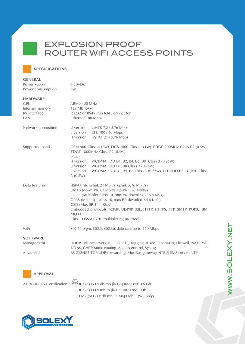
ATEX / IECEx Certification II 2 (1) G Ex db mb [ia Ga] IIA/IIB/IIC T6 Gb II 2 (1) D Ex mb tb [ia Da] IIIC T85°C Db I M2 (M1) Ex db mb [ia Ma] I Mb (WS only) w
ww
.SO
LE
XY
.ne
t
EXPLOSION PROOFROUTER WiFi ACCESS POINTS
APPROVAL
GENERALPower supply 6-30VDCPower consumption 5W
HARDWARECPU ARM9 450 MHzInternal memory 128 MB RAMRS Interface RS232 or RS485 via RJ45 connectorLAN Ethernet 100 Mbps
Network connection U version UMTS 7.2 / 5.76 Mbps L version LTE 100 / 50 Mbps H version HSPA+ 21 / 5.76 Mbps
Supported bands GSM 900 Class 4 (2W), DCS 1800 Class 1 (1W), EDGE 900MHz Class E2 (0.5W), EDGE 1800MHz Class E2 (0.4W)
plus: H version WCDMA FDD B1, B2, B4, B5, B8 Class 3 (0.25W) U version WCDMA FDD B1, B8 Class 3 (0.25W) L version WCDMA FDD B1, B5, B8 Class 3 (0.25W), LTE FDD B3, B7,B20 Class
3 (0.2W)
Data features HSPA+ (downlink 21 Mbit/s, uplink 5,76 Mbit/s) UMTS (downlink 7,2 Mbit/s, uplink 5,76 Mbit/s) EDGE (Multi-slot class 10, max BR downlink 236,8 Kb/s) GPRS (Multi-slot class 10, max BR downlink 85,6 Kb/s) CSD (Max BR 14,4 Kb/s) Embedded protocols TCP/IP, UDP/IP, SSL, HTTP, HTTPS, FTP, SMTP, POP3, IBM
MQTT Class B GSM 07.10 multiplexing protocol
WiFi 802.11 b/g/n, 802.3, 802.3u, data rate up to 150 Mbps
SOFTWAREManagement DHCP (client/server), IEEE 802.1Q tagging, IPsec, OpenVPN, Firewall, NAT, PAT,
DDNS, CARP, Static routing, Access control, SyslogAdvanced RS-232/485-TCP/UDP forwarding, ModBus gateway, NTRIP, SMS server, NTP
EXPLOSION PROOFROUTER WiFi ACCESS POINT
DIMENSIONAL DRAWINGS
ww
w.S
OL
EX
Y.n
et
SOLEXY SRL SOLEXY USA, LLCVia Enrico Fermi, 2 10178 International Blvd.25015 Desenzano del Garda (BS) Italy Cincinnati (OH) 45246 USAPhone (+39) 030 787.0.787 | [email protected] Phone (+1) 513.860.5465 | [email protected]
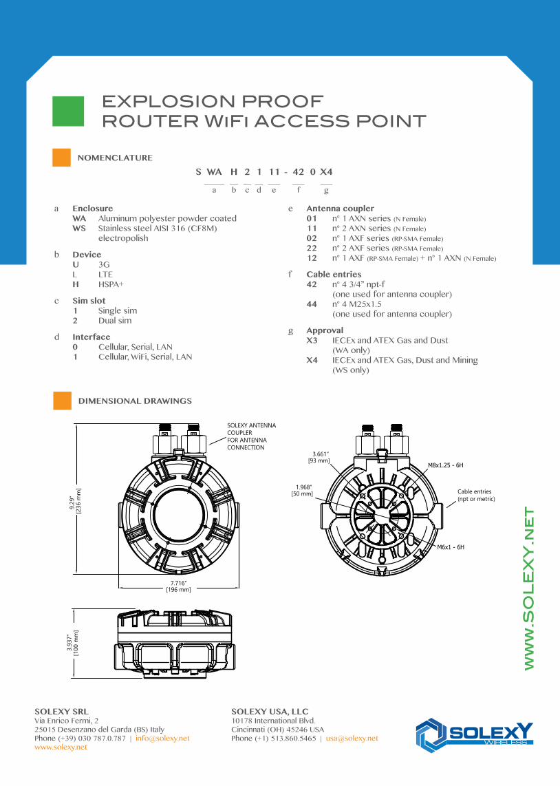
NOMENCLATURES WA H 2 1 11 - 42 0 X4 _____ __ __ __ ___ ___ ___ a b c d e f g
a Enclosure WA Aluminum polyester powder coated WS Stainless steel AISI 316 (CF8M) electropolish
b Device U 3G L LTE H HSPA+
c Sim slot 1 Single sim 2 Dual sim
d Interface 0 Cellular, Serial, LAN 1 Cellular, WiFi, Serial, LAN
e Antenna coupler 01 n° 1 AXN series (N Female) 11 n° 2 AXN series (N Female) 02 n° 1 AXF series (RP-SMA Female) 22 n° 2 AXF series (RP-SMA Female) 12 n° 1 AXF (RP-SMA Female) + n° 1 AXN (N Female)
f Cable entries 42 n° 4 3/4” npt-f (one used for antenna coupler) 44 n° 4 M25x1.5 (one used for antenna coupler)
g Approval X3 IECEx and ATEX Gas and Dust (WA only) X4 IECEx and ATEX Gas, Dust and Mining (WS only)
3.93
7”[1
00 m
m]
SOLEXY ANTENNACOUPLER FOR ANTENNACONNECTION
7.716”[196 mm]
9.29
”[2
36 m
m] Cable entries
(npt or metric)
M8x1.25 - 6H
M6x1 - 6H
1.968”[50 mm]
3.661”[93 mm]

www.solexy.net - [email protected]
SOLEXY SRLvia Enrico Fermi, 2
25015 Desenzano del Garda (BS) ItalyPhone +39 030 787.0.787
Fax. +39 030 787.0.777
SOLEXY USA, LLC10178 International Blvd.
Cincinnati, OH 45246 USAPhone +1-513-860-5465
Fax +1-513-860-5464


![Lecture 5: Variance Reduction - LAGA - Accueilkebaier/Lecture5.pdfAntithetic Variables Antithetic Variables Assume that we aim at computing ˇ= E(g(U)), where U ˘U([0;1]): We simulate](https://static.fdocument.org/doc/165x107/5f8dc882f6ffaa497a7a5af9/lecture-5-variance-reduction-laga-accueil-kebaierlecture5pdf-antithetic-variables.jpg)