
GMPLS MλPLSPLS - BME-HITjakab/edu/litr/GMPLS/GMPLS_overview.pdf · GMPLS MλPLSPLS Ana Yun Temas...
37
GMPLS M GMPLS M GMPLS M GMPLS MλPLS PLS PLS PLS Ana Yun Temas Avanzados de Redes de Ordenadores Departamento de Ingeniería de Sistemas Telemáticos Curso 2001-2002
Transcript of GMPLS MλPLSPLS - BME-HITjakab/edu/litr/GMPLS/GMPLS_overview.pdf · GMPLS MλPLSPLS Ana Yun Temas...

GMPLS MGMPLS MGMPLS MGMPLS MλλλλPLSPLSPLSPLS
Ana Yun Temas Avanzados de Redes de Ordenadores
Departamento de Ingeniería de Sistemas Telemáticos
Curso 2001-2002
GMPLS MλPLS ...................................................................................................................................... 1 Introduction.................................................................................................................................................. 3 DWDM Optical Components ...................................................................................................................... 4
DWDM .................................................................................................................................................... 4 OXC, Optical Cross Connect ................................................................................................................... 8
Typical WXC Design ......................................................................................................................... 8 Integrated WXC Design .................................................................................................................... 9
Optical Switching .................................................................................................................................... 9 OXC future: All Optical Network.......................................................................................................... 10
Evolution towards Photonic Networks ...................................................................................................... 13 Network Architectures with G-MPLS ................................................................................................... 14
Routing, Signaling and Link Management Protocols to support Generalized MPLS (G.MPLS).............. 16 MPLS routing and signaling adaptations ............................................................................................... 16
MPLS ................................................................................................................................................ 16 Labels in Optical Networks............................................................................................................. 17
Routing .................................................................................................................................................. 18 LSP Hierarchy ....................................................................................................................................... 19 Link Bundling ........................................................................................................................................ 21 Link Management protocol (LMP) ........................................................................................................ 21 Signaling Techniques............................................................................................................................. 22 Enhancements to signaling .................................................................................................................... 24 GMPLS Protection and Restoration Techniques ................................................................................... 27 MPLS Traffic Engineering Control with Optical Crossconnects.......................................................... 28
OXCs, LSRs, Optical Trails and Explicit LSPs ............................................................................ 30 Explicit LSPs and Optical Channel Trails..................................................................................... 31 Generic Requirements for the OXC Control Plane ...................................................................... 31 MPLS Traffic Engineering as Generic Control Plane for OXCs ................................................ 32 MPLS Traffic engineering control plane with OXCs ................................................................... 33
Summary.................................................................................................................................................... 35 Bibliografía ................................................................................................................................................ 37
Introduction Current circuit-switched transport networks, such as plesiochronous digital hierarchy (PDH) and synchronous optical network/synchronous digital hierarchy (SONET/SDH), have traditionally used centralized network management for connection control. Generalized multiprotocol label switching, GMPLS, is a suite of protocols extensions that provides common control to packet, TDM, wavelength and fiber services. These extensions affect routing and signaling protocols for activities such as label distribution, traffic engineering, and protection and restoration; and enable rapid provisioning and management of network services. GMPLS, supports not only devices that perform packet switching, but also those that perform switching in the time, wavelength, and space domains. As mentioned before the development of GMPLS requires modifications to current signaling and routing protocols, but it has also triggered the development of new protocols such as the Link Management Protocol. Open Shortest Path First Internet routing protocol and IS-IS Intradomain Routing Protocol, are both popular routing protocols to support GMPLS. The advent of G-MPLS created a twofold opportunity for the telecommunications industry. First, it offers a consolidated control plane and extends topology awareness and bandwidth management across al network layers, and thus enables evolution to new, more efficient and cost-effective core network architectures. Second, G-MPLS was developed from MPLS and MPλS, but is designed for use with different traffic types. G-MPLS therefore offers the means by which networks can be scaled and simplified by deployment of a new class of network element designed to handle multiple traffic types simultaneously. The purpose of this document is to cover the following points related with the evolution towards a future all-optical network:
� GMPLS and DWDM evolution relation � OXC, new all optical cross connects � GMPLS evolution from MPLS and MλPS � Routing and signaling new features for GMPLS � MPLS traffic engineering with OXC � Networks all –optical, the future?
DWDM Optical Components
DWDM
Overview Despite the big hits being dealt by investors to all segments of the telecommunications industry, over the next five years the market for dense wavelength division multiplexing (DWDM) optical systems is expected to grow at a 28 percent compounded annual rate. Two factor are pushing this grow, the internet continuous growing over 100 percent a year, regardless of conditions in the financial markets; and optical equipment as the only solution that can, in the long-term, cost-effectively meet the increased demand for bandwidth in long-haul and metropolitan networks.
The phone companies are continually expanding their fiber distribution networks further and further into local neighbourhoods, trying to meet the demand for data services. This capacity expansion will become even more necessary as time goes on. Long-haul networks are flooding metropolitan networks with increasing volumes of data, while access networks are being strained by the need to support demanding Web applications. However, the time division multiplexing (TDM)-based technologies used in most fiber-based metropolitan networks are too costly and inflexible to meet the growing data traffic demand.
Synchronous optical networking (SONET) and synchronous digital hierarchy (SDH) standards were set up for the transmission of TDM digital signals—usually voice traffic—over fiber in the 1980s. Using TDM, a data stream at a higher bit rate is generated by multiplexing together lower bit rate channels. High-capacity SONET/SDH systems now operate at levels up to 10 Gbit/s (OC-192), and the architecture has proved very reliable for the transport of voice services.
However, SONET does have some significant limitations. As higher bit rates are used—40 Gbit/s (OC-768) and above—physical limitations in laser sources and optical fiber impose limits on the practice of endlessly increasing the bit rate on each signal. As customers demand more services, and need to carry more data traffic, SONET has reached a point of diminishing returns.
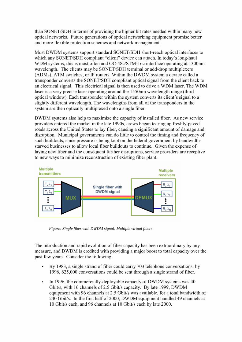
Wave division multiplexing (WDM) refers to an optical transmission technique where multiple optical signals are transmitted on a single optical fiber using different wavelengths. In today´s high-end WDM systems designed for long distance communications, each optical signal (often referred to as a channel or a wavelength) can operate at up to 2,5Gps or 10 Gbps. Currently, available systems support from 32 to 64 channels and vendors are promising up to 160 channel carry more than 1 terabit/s of information.
The term dense wave division multiplexing (DWDM) is often used to describe systems supporting a large amount of channels, normally 16 or more. DWDM systems, can carry multiple data bit rates, allowing multiple channels to be carried on a single fiber. The technique quite literally uses different colors of light down the same fiber to carry different channels of information, which are then separated out at the distant end by a type of grating that identifies each distinct color. DWDM has been more successful
than SONET/SDH in terms of providing the higher bit rates needed within many new optical networks. Future generations of optical networking equipment promise better and more flexible protection schemes and network management.
Most DWDM systems support standard SONET/SDH short-reach optical interfaces to which any SONET/SDH compliant “client” device can attach. In today´s long-haul WDM systems, this is most often and OC-48c/STM-16c interface operating at 1300nm wavelength. The clients may be SONET/SDH terminal or add/drop multiplexers (ADMs), ATM switches, or IP routers. Within the DWDM system a device called a transponder converts the SONET/SDH compliant optical signal from the client back to an electrical signal. This electrical signal is then used to drive a WDM laser. The WDM laser is a very precise laser operating around the 1550nm wavelength range (third optical window). Each transponder within the system converts its client´s signal to a slightly different wavelength. The wavelengths from all of the transponders in the system are then optically multiplexed onto a single fiber.
DWDM systems also help to maximize the capacity of installed fiber. As new service providers entered the market in the late 1990s, crews began tearing up freshly-paved roads across the United States to lay fiber, causing a significant amount of damage and disruption. Municipal governments can do little to control the timing and frequency of such buildouts, since pressure is being kept on the federal government by bandwidth-starved businesses to allow local fiber buildouts to continue. Given the expense of laying new fiber and the consequent further disruptions, service providers are receptive to new ways to minimize reconstruction of existing fiber plant.
Figure: Single fiber with DWDM signal: Multiple virtual fibers
The introduction and rapid evolution of fiber capacity has been extraordinary by any measure, and DWDM is credited with providing a major boost to total capacity over the past few years. Consider the following:
• By 1983, a single strand of fiber could carry 703 telephone conversations; by 1996, 625,000 conversations could be sent through a single strand of fiber.
• In 1996, the commercially-deployable capacity of DWDM systems was 40 Gbit/s, with 16 channels of 2.5 Gbit/s capacity. By late 1999, DWDM equipment with 96 channels at 2.5 Gbit/s was available, for a total bandwidth of 240 Gbit/s. In the first half of 2000, DWDM equipment handled 49 channels at 10 Gbit/s each, and 96 channels at 10 Gbit/s each by late 2000.
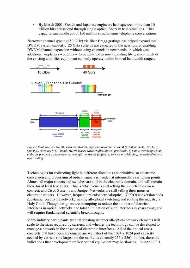
• By March 2001, French and Japanese engineers had squeezed more than 10 trillion bits per second through single optical fibers in trial situations. This capacity can handle about 150 million simultaneous telephone conversations.
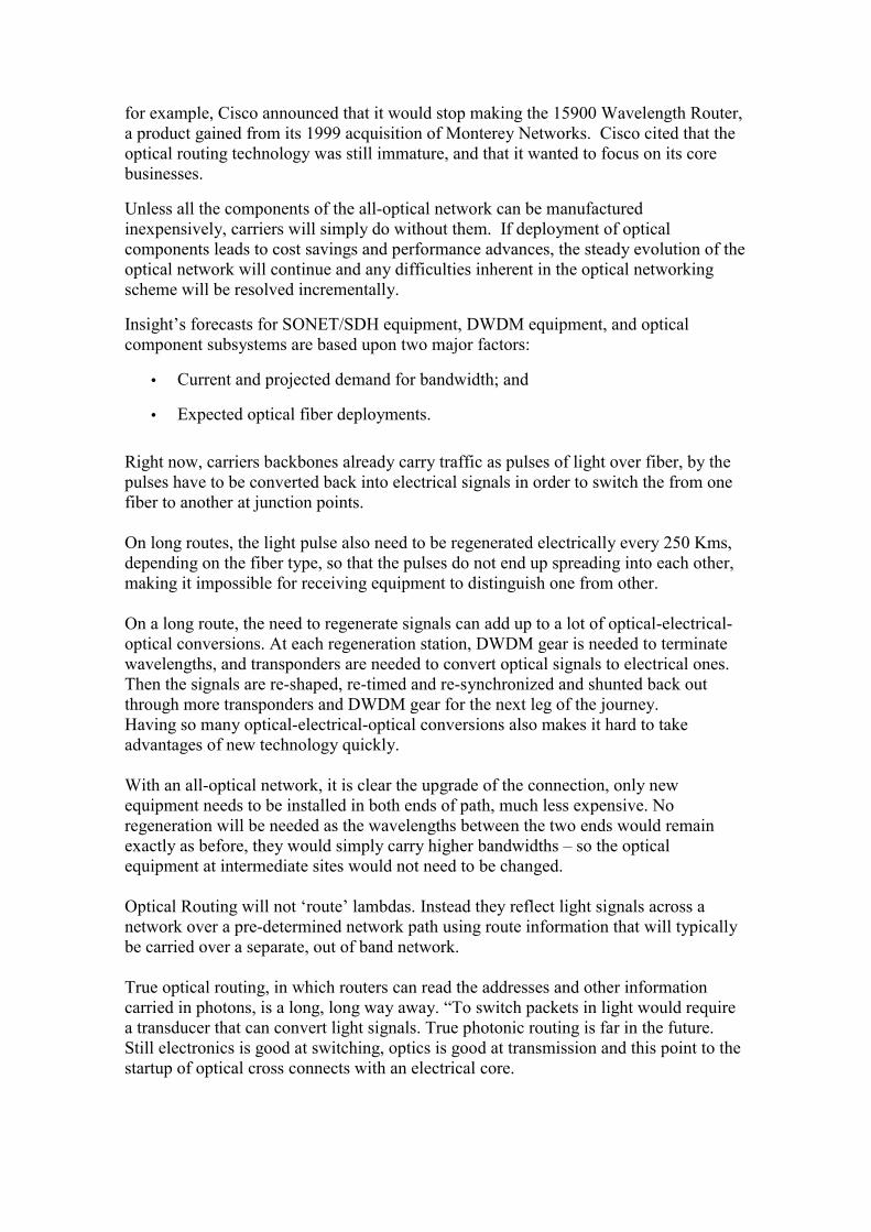
Narrower channel spacing (50 GHz) via fiber Bragg gratings has helped expand total DWDM system capacity. 25 GHz systems are expected in the near future, enabling DWDM channel expansion without using channels in new bands, in which case additional amplifiers would have to be installed in much existing fiber, since much of the existing amplifier equipment can only operate within limited bandwidth ranges.
Figure: Evolution of DWDM: more bandwidth, high channel-count DWDM (>300channels, <25 GHz spacing), extended (“L”) band DWDM leased wavelengths, optical protection, dynamic wavelength plan, end-user protocol directly over wavelengths, end-user (software) service provisioning, embedded optical layer testing.
Technologies for redirecting light in different directions are primitive, so electronic conversion and processing of optical signals is needed at intermediate switching points. Almost all major routers and switches are still in the electronic domain, and will remain there for at least five years. This is why Ciena is still selling their electronic cross-connect, and Cisco Systems and Juniper Networks are still selling their monster electronic routers. However, frequent optical/electrical/optical (O/E/O) conversion adds substantial cost to the network, making all-optical switching and routing the industry’s Holy Grail. Though designers are attempting to reduce the number of electrical interfaces in optical networks, the total elimination of such interfaces is years away, and will require fundamental scientific breakthroughs.
Many industry participants are still debating whether all-optical network elements will scale to the sizes required by carriers, and whether the technology can be developed to manage a network in the absence of electronic interfaces. All of the optical cross-connects that have been announced are well short of the 1024 x 1024 port capacity needed by carriers (the largest on the market is currently 256 x 256). In fact, there are indications that development on key optical equipment may be slowing. In April 2001,
for example, Cisco announced that it would stop making the 15900 Wavelength Router, a product gained from its 1999 acquisition of Monterey Networks. Cisco cited that the optical routing technology was still immature, and that it wanted to focus on its core businesses.
Unless all the components of the all-optical network can be manufactured inexpensively, carriers will simply do without them. If deployment of optical components leads to cost savings and performance advances, the steady evolution of the optical network will continue and any difficulties inherent in the optical networking scheme will be resolved incrementally.
Insight’s forecasts for SONET/SDH equipment, DWDM equipment, and optical component subsystems are based upon two major factors:
• Current and projected demand for bandwidth; and
• Expected optical fiber deployments. Right now, carriers backbones already carry traffic as pulses of light over fiber, by the pulses have to be converted back into electrical signals in order to switch the from one fiber to another at junction points. On long routes, the light pulse also need to be regenerated electrically every 250 Kms, depending on the fiber type, so that the pulses do not end up spreading into each other, making it impossible for receiving equipment to distinguish one from other. On a long route, the need to regenerate signals can add up to a lot of optical-electrical-optical conversions. At each regeneration station, DWDM gear is needed to terminate wavelengths, and transponders are needed to convert optical signals to electrical ones. Then the signals are re-shaped, re-timed and re-synchronized and shunted back out through more transponders and DWDM gear for the next leg of the journey. Having so many optical-electrical-optical conversions also makes it hard to take advantages of new technology quickly. With an all-optical network, it is clear the upgrade of the connection, only new equipment needs to be installed in both ends of path, much less expensive. No regeneration will be needed as the wavelengths between the two ends would remain exactly as before, they would simply carry higher bandwidths – so the optical equipment at intermediate sites would not need to be changed. Optical Routing will not ‘route’ lambdas. Instead they reflect light signals across a network over a pre-determined network path using route information that will typically be carried over a separate, out of band network. True optical routing, in which routers can read the addresses and other information carried in photons, is a long, long way away. “To switch packets in light would require a transducer that can convert light signals. True photonic routing is far in the future. Still electronics is good at switching, optics is good at transmission and this point to the startup of optical cross connects with an electrical core.

OXC, Optical Cross Connect Wavelength Cross Connects (WXCs) are a class of optical switches defined to dynamically route the transport of wavelengths between fibers in DWDM systems. More generic optical cross connects (OXCs), also called optical core switches (OCS), are designed to switch optical channels without regard to wavelength. WSCs are typically deployed to add/drop wavelengths from a DWDM stream, to route wavelengths in DWDM mesh networks and to provide path protection and restoration in DWDM rings and meshes.
Figure: OCX
Typical WXC Design Typical wavelength switching architectures are based on a 3-step process:
o de-multiplex the wavelengths from the DWDM input fibers into individual optical channels
o switch the optical channels to the destination fibers using a cross connect switch o regenerate the DWDM wavelengths and multiplex the onto the output fibers.
An OCS based on either an electrical switching fabric (O-E-O) or an all-optical switching fabric (O-O-O) is usually at the heart of this system. The OCS must be sized to provide an input and output port per wavelength resulting in high port-count requirements. The costs of building a typical WXC node as described are extremely high due to several factors: the cost of the demux and mux optics, the high per-port costs of the OCS and the cost of regenerating each wavelength. A typical installation will incur several O-E-O conversions. The first may occur at the termination of the DWDM wavelength in the demux terminal. The input and output ports of the OCS each require conversions, even for emerging all-optical switching fabrics. Finally each DWDM wavelength must be regenerated for transmission to the next node of the network.
Integrated WXC Design An alternative to the traditional discrete method of engineering a WXC is the Integrated Wavelength Cross-Connect. The Integrated WXC combines the demux/switch/mux processes into a single photonic stage. An integrated WXC performs the same function as a conventional 3-stage WXC built using an OCS, but at significantly lower size, power and cost. All of the inputs and outputs of the Integrated WXC are DWDM fibers. Consequently, the total number of ports required for the WXC are equal to the number of DWDM input/output fibers instead of the number of wavelengths as in the OCS-based design. Since the demux and mux functions are integrated into the switching operation, there are no external optics or opto-electronics required to separate and recombine the wavelengths –again resulting in huge savings in equipment cost, power and space. In an integrated WXC, the wavelength is preserved as it passes through the switch, thereby eliminating the need to regenerate each wavelength. This is an important feature as DWDM systems move to ultra-long-haul transmission and do not require frequent regeneration. Since the integrated WXC is purely photonic, it has the benefits of transparency to protocol and bit rates. In all-optical switching systems such as integrated WXCs, several network-level engineering issues must be resolved –performance and fault monitoring, optical power, power balancing and wavelength contention. All-optical systems require the ability to monitor performance and isolate faults without O-E-O conversion of the wavelengths. Non-intrusive monitor taps on the WXC input and output are connected to OPM (Optical Performance Monitoring) modules to make this possible. OPM modules can also be shared among WXC ports, further reducing the cost. Since the inputs and output of an integrated WXC are DWDM signals, conventional optical amplifiers are used to restore optical power. With the cost of the amplifiers amortized over all the wavelengths in the fiber, the per wavelength cost is low. Dynamic channel equalization can be applied at the amplifier inputs to adjust the optical power for imbalances that may occur from wavelengths arriving from different sources.
Optical Switching Optical switches consist of bundles of optical fibers. An optical switch can choose to switch any possible subset of the optical bundle as a single unit – all the traffic in such unit on the incoming interface is switched to a corresponding type and size of unit on the outgoing interface. As switching variants used in optical networks can be found hereafter. A key feature of all of them is that the OXC switches large flows of data as a unit, and does so based on quantities (wavelengths, timeslots, …) inherent in the network medium rather than by examining data headers packet or application level.
� Switching Entire Fibers: switch an entire fiber, all the data arrives on a single fiber is switched to be transmitted out of another fiber
� Lambda switching: within a single fiber, the available bandwidth can divided up by frequency into wavelengths, an OXC switches all the data in wavelength A on the incoming fiber to wavelength B on the outgoing fiber. A restriction of some optical switches is that they are incapable of wavelength conversion, in which case B must be the same as A.
� Waveband switching: a generalization of lambda switching. If a fiber’s bandwidth is divided by frequency, wavelengths may be grouped together and switched as a block. This saves signaling and switching hardware. It can also be viewed as an LSP tunnel that switches each of the payload wavelength LSPs in the same way.
� Time Division Multiplexing: a fiber’s bandwidth can also be divided up by timeslots. The optical signal is seen as a sequence of data frames, with N frames each of size S traveling every second (making up the total fiber bandwidth N*S), and bandwidth is allocated for a particular data flow by reserving a portion of each frame. The basic frame sizes, and the hierarchies, by which a single frame can be divided up into timeslots, are the subject of several standards, notably SONET and SDH.
OXC future: All Optical Network Several manufacturers are investing efforts on developing different solutions for an All-Optical network based on an OXC full optical. These are some examples: Xros and X-1000 Xros Inc. (www.xros.com) unveiled an optical cross connect called the X-1000 last march. This new cross connect can scale 1152 pairs of input and output ports, a big advance on existing developments and the first cross connect to reach the 1000 port threshold often cited as a minimum requirement by carriers. The need of optical cross connects of this size will help to connect together the massive increase in the numbers of wavelengths in their backbones –a result of the widespread deployment DWDM technology. In this OXC, light is not converted into electrical signals to be switched, as is the case of some optical cross connects. All-optical, this means that it will carry whatever can be obtained within a wavelength, now and in the future. It will not need upgrading to carry higher bandwidths as new transmission technologies arrive. The X-1000 consists of 1152 mirrors, each measuring 2 millimeters square, inside a six-inch square piece of silicon. Each mirror is coated with gold leaf to reflect the maximum amount of light and is hung in two concentric frames, in the same way as a compass is mounted on gimbals, so it can be tilted in any direction by applying electrical current. Connections between input and output ports are set up automatically, in response to signaling, in less than 50 milliseconds. Fast enough for protection systems –setting up alternative paths across backbones in the event of a line or equipment failure. Still, Xros´s X-1000 has some snags. Light becomes weaker as it passes through its equipment, so in some circumstances it may not be used to replace existing electrical
cross-connects. The adjoining DWDM terminals might not have powerful enough lasers to pump light across the X-1000. Although X-1000 can automatically reroute wavelengths around failures, there is no mechanism to sense failures at present. A signaling standard is needed to carry this information from the DWDM terminals to the cross connect. The technology is unproven, by now is only a prototype, but Xros expects to start trials by the end of the summer and begin commercial shipments early next year. Siemens and TransXpress OSN Siemens launched an OXC, the TransXpress Optical Service Node (OSN), an optical solution for the sort of capacity of future carriers, an optical cross connect, all-optical that can be configured to connect as many as 2160 wavelengths. Unfortunately, Siemens’ OSN is another example of vendors promising more than they can really deliver. It is actually a combination of a 2160 port patch panel, a 512 port optical cross-connect and some management software. The combination enables carriers to automate provisioning of a small portion of the wavelengths, using the optical cross connect. The remainder of the ports will have to be connected together manually. In this case, OSN’s management system will turn on lights next to the ports to be connected together. Siemens says that its solution is a good half-way house on the road towards very high capacity, all-optical networks. It enables carriers to connect large numbers of wavelengths today, albeit manually. And it paves the way for automating a larger proportion of the provisioning process in the future by installing bigger optical cross connects in the OSN as they become available. Lucent LambdaRouter Lucent launched last November its LambdaRouter, described as “the industry’s first all-optical router”. First of all, the product was not a real ‘all-optical’, the Lambda Router switches light, but the outgoing signals have to regenerated electrically before they can be transmitted any distance. Secondly, it is not a router, it does not read layer 3 information and make decisions on how to send traffic based on the most expedient route. Essentially, Lucent did built a relatively large, 256 by 256 port, prototype optical switch using micro electro-mechanical (MEM) technology. This is far from the all-optical development. In reality, the dream of all optical networks –which promise virtually limitless bandwidth, ultra low costs and on-demand provisioning –is going to take a long time to materialize. To gain a better idea of how long, Light Reading has investigated vendors’ claims and come up with a road map of the breakthroughs necessary before all optical networking becomes a reality –from the elimination of electrical regeneration, to the development of true optical crossconnects and real optical routing. Once light can be transmitted over long distances without electrical regeneration, the next big challenge will be to switch light without converting it back into electrical signals, using optical cross connects. This will let carriers provision optical circuits over their backbones from a remote console, without sending engineers to sites. The development of genuine optical cross connects is at an early stage. Most of the existing ones are not all optical. They have an electrical core, which would need upgrading when transmission speeds were increased.

The opposite is true of Lucent’s LambdaRouter, which has an optical core, but shunts outlight signals that are so feeble that they need electrical regeneration to travel any distance. Essentially, the weak signals are the price that Lucent has had to pay for achieving a relatively large-scale optical switch. The scalability comes from using MEM, a semiconductor technology that embeds large arrays of microscopic mirrors in silicon and enables each mirror to be tilted to deflect individual beams of light. Most of the carriers are now waiting for a 1012 by 1012 port capacity for optical cross connects. The downside of MEM is that a lot of light gets lost. The technology was invented for the large screens seen at pop concerts and sporting events, and has been adapted for use in telecom switches.
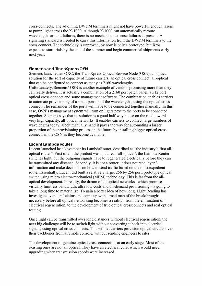
Evolution towards Photonic Networks Today’s synchronous optical network/synchronous digital hierarchy (SONET/SDH) transport network infrastructure provides a guaranteed level of performance and reliability for voice calls and leased lines. However, since 1995, there has been a dramatic increase in data traffic, driven primarily by Internet and VPNs, and at the same time a need to minimize the cost. The challenge is in the new solutions for service providers that enable to carry large volume of traffic in a cost-efficient manner within the current network architecture. Typically today’s network has four layers: IP for carrying applications and services, asynchronous transfer mode (ATM) for traffic engineering, SONET/SDH for transport, and dense wavelength-division multiplexing (DWDM) for capacity. This architecture is slow to scale very large volumes of traffic, and at the same time fairly cost-ineffective. In a multilayer architecture one of the layers can limit the scalability of the entire network, a well as add to he cost of the entire network. Effective transport optimizes the cost of data multiplexing as well as data switching over a wide range of traffic volumes. DWDM is a cost-efficient multiplexing technique that offers significant technical advantages. DWDM increases the bandwidth-carrying capacity of a single optical fiber by effectively creating multiple virtual fibers, each carrying multigigabits of traffic per second, on a single fiber. Likewise, optical cross-connects (OXCs) are likely to emerge as the preferred option for switching multigigabit or even terabit data streams, since electronic per-packet processing is avoided.
Figure: GMPLS brings together services and transport
As it is widely expected that IP will be the predominant traffic carried over data networks as well as the IP packet based the dominant multiplexing technology for data streams smaller than those suitable for DWDM. As the grow of capabilities on both routers and OXCs, the high rates of optical transport suggest the distinct possibility of bypassing the SONET/SDH and ATM layers. In the end, the results is a simpler, more cost-efficient network that will transport a wide range of data streams and very large volumes of traffic.
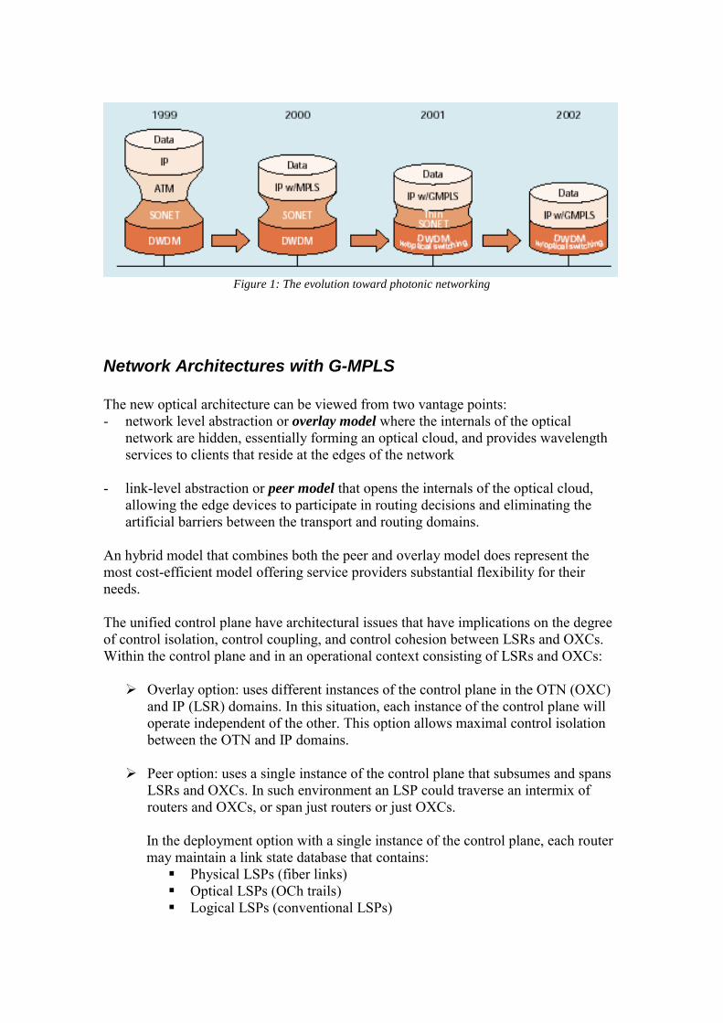
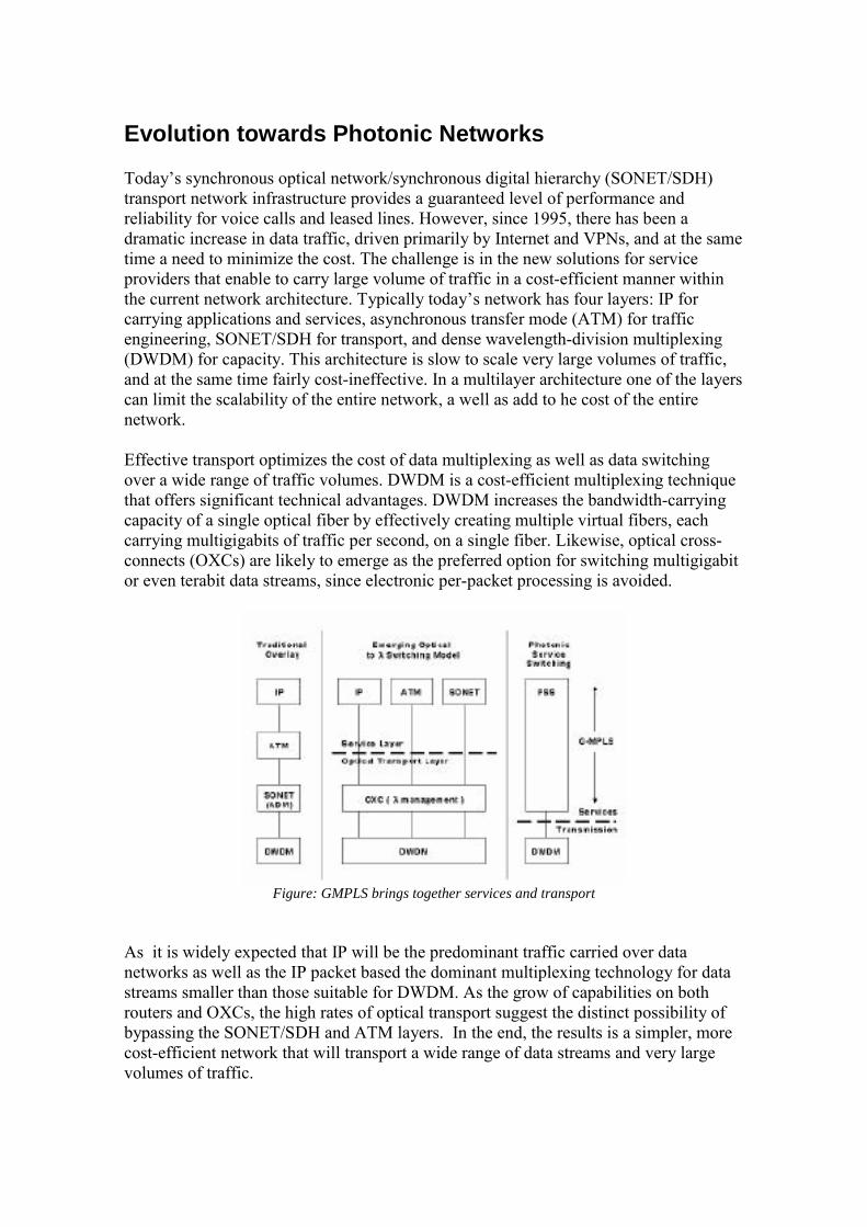
Figure 1: The evolution toward photonic networking
Network Architectures with G-MPLS The new optical architecture can be viewed from two vantage points: - network level abstraction or overlay model where the internals of the optical
network are hidden, essentially forming an optical cloud, and provides wavelength services to clients that reside at the edges of the network
- link-level abstraction or peer model that opens the internals of the optical cloud,
allowing the edge devices to participate in routing decisions and eliminating the artificial barriers between the transport and routing domains.
An hybrid model that combines both the peer and overlay model does represent the most cost-efficient model offering service providers substantial flexibility for their needs. The unified control plane have architectural issues that have implications on the degree of control isolation, control coupling, and control cohesion between LSRs and OXCs. Within the control plane and in an operational context consisting of LSRs and OXCs:
� Overlay option: uses different instances of the control plane in the OTN (OXC) and IP (LSR) domains. In this situation, each instance of the control plane will operate independent of the other. This option allows maximal control isolation between the OTN and IP domains.
� Peer option: uses a single instance of the control plane that subsumes and spans
LSRs and OXCs. In such environment an LSP could traverse an intermix of routers and OXCs, or span just routers or just OXCs.
In the deployment option with a single instance of the control plane, each router may maintain a link state database that contains:
� Physical LSPs (fiber links) � Optical LSPs (OCh trails) � Logical LSPs (conventional LSPs)
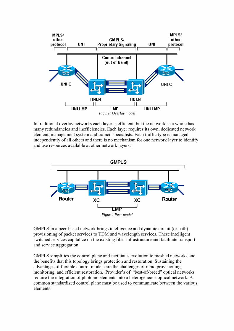
Figure: Overlay model
In traditional overlay networks each layer is efficient, but the network as a whole has many redundancies and inefficiencies. Each layer requires its own, dedicated network element, management system and trained specialists. Each traffic type is managed independently of all others and there is no mechanism for one network layer to identify and use resources available at other network layers.
Figure: Peer model
GMPLS in a peer-based network brings intelligence and dynamic circuit (or path) provisioning of packet services to TDM and wavelength services. These intelligent switched services capitalize on the existing fiber infrastructure and facilitate transport and service aggregation. GMPLS simplifies the control plane and facilitates evolution to meshed networks and the benefits that this topology brings protection and restoration. Sustaining the advantages of flexible control models are the challenges of rapid provisioning, monitoring, and efficient restoration. Provider’s of “best-of-breed” optical networks require the integration of photonic elements into a heterogeneous optical network. A common standardized control plane must be used to communicate between the various elements.
Routing, Signaling and Link Management Protocols to support Generalized MPLS (G.MPLS)
MPLS routing and signaling adaptations IP routing has evolved to include new functionality under multiprotocol label switching (MPLS), and a recent work extending MPLS as a control plane that can be used not merely with routers, but also with legacy equipment (SONET, ATM) and newer devices like (OXCs). A common control plane is the essential component in the evolution of open and interoperable optical networks, simplifies operations and management, reduces cost of operations, and avoids “reinventing the wheel” as it is based on proven signaling and routing. Some modifications and additions are required to the MPLS routing and signaling protocols to adapt to the peculiarities of photonic switches. - A new Link Management Protocol (LMP) designed to address issues related to
link management in optical networks using photonic switches - Enhancements to the Open Shortest Path First/Intermediate System to
Intermediate System (OSPF/IS-IS) routing protocols to advertise availability of optical resources in the network
- Enhancement to the Resource Reservation Protocol (RSVP)/Constraint-Based
Routing Label-Distributed Protocol (CR-LDP) signaling protocols for traffic engineering purposes that allow a label-switched path (LSP) to be explicitly specified across the optical core
- Scalability enhancements such as hierarchical LSP formation, link bundling, and
unnumbered links
MPLS MPLS basic ideas are: - Forwarding information (label) separate from the content of IP header - A single forwarding paradigm (label swapping), multiple routing paradigms - Multiple link-specific forwarding paradigm: “shim,” virtual connection/path
identifier (VCI/VPI), frequency slot (wavelength), time slot - The flexibility to form forwarding equivalence classes (FECs) - A forwarding hierarchy via label stacking As forwarding information is independent from IP header allows MPLS to be used with devices such as OXCs, whose data plane cannot recognize IP header- Label switch routers (LSRs) forward data using the label carried by the data. This label, combined
with the port on which the data was received, is used to determine the output port and outgoing label for the data. MPLS control plane operates in terms of the label swapping and forwarding paradigm abstraction, and the MPLS data plane allows multiple link-specific realizations of this abstraction. A wavelength could be viewed as an implicit label. Finally, the concept of a forwarding hierarchy via label stacking enables interaction with devices that can support only a small label space. This property of MPLS is essential in the context of OXCs and DWDMs since the number of wavelengths is not very large. Constraint based routing is a combination of extensions to existing IP link-sate routing protocols (OSPF and IS-IS) with RSVP or CR-LDP as the MPLS control plane, and the Constrained Shortest-Path-First (CSPF) heuristic. The extensions to OSPF and IS-IS allow nodes to exchange information and even policy information. This information is used by the CSPF heuristic to compute paths subject to specified resource and/or policy constraints. For example, RSVP-TE or CR-LDP are used to establish the label forwarding state along the routes computes by a CSPF-based algorithm; this creates the LSP. The MPLS data plane us used to forward the data along the established LSPs. Constraint-based routing is used today for two purposes: traffic engineering and fast reroute. With suitable network design, the constraint-based routing of IP/MPLS can replace ATM as the mechanism for traffic engineering. Likewise, fast reroute offers an alternative to SONET as a mechanism for protection/restoration. Future evolution of MPLS technologies, and G.MPLS enhancements, are several emerging synergies between LSRs and photonic switches, and between an LSP and optical trail. An optical trail is an end-to-end path composed exclusively of photonic elements without optical-electronic conversions. As in switching labels in an LSR, a photonic switch toggles wavelengths from an input to an output port. Establishing an LSP involves configuring each intermediate LSR to map a particular input label and port to an output label and port. The process of establishing an optical trail involves configuring each intermediate photonic switch to map a particular input lambda and port. As in LSRs, photonic switches need routing protocols like OSPF or IS-IS to exchange link-state topology and other path computation. Protocols as RSVP and LDP are needed to automate the path establishment process.
Labels in Optical Networks In non-generalized MPLS, a label is a number (up to 32 bits) that gets written into the protocol header fields of data packets travelling on the link. Once a pair of LSRs have agreed this number, they also agree that the corresponding data flow consists of all data packets with this number in the appropriate protocol header field, and will switch all the packets in this flow in the same way. This kind of label does not necessarily imply a relationship to bandwidth allocation or quality of service for the corresponding data flow. The label value might no imply anything about how frequently packets with that value might arrive or what bandwidth is available.
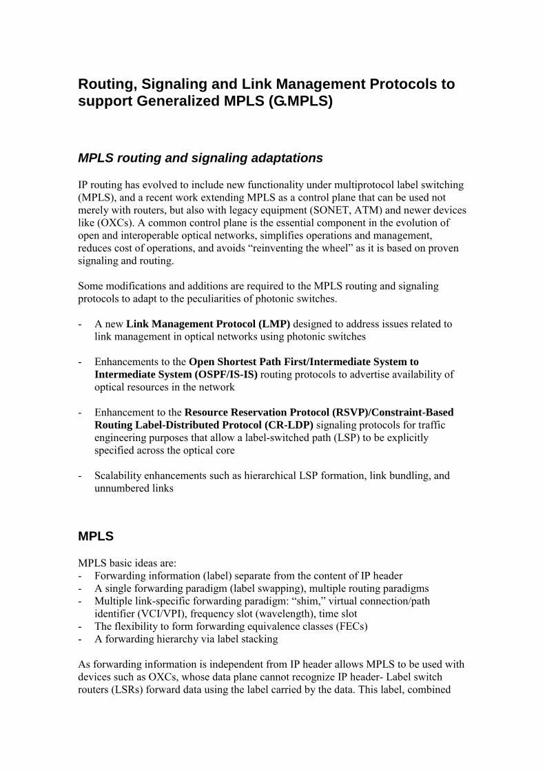
Traffic Engineering label distribution protocols (such as RSVP and CR-LDP) facilitate quality of service and bandwidth negotiation as part of the label exchange. Other protocols, as LDP, simply exchange labels. GMPLS generalizes the idea that a label is sufficient to identify a traffic flow. GMPLS extends the representation of a label from a single 32 bit number to an arbitrary length byte array and introduces the Generalized Label object (in RSVP) and Generalized Label TLV (in CR-LDP) to carry both the label itself and related information. Different switching quantities used in optical networks can be represented with GMPLS labels:
� Whole fiber labels: a link between LSRs may consist of a bundle of optical fibers, LSRs may choose to allocate a whole fiber to a data flow, simply need to agree on which fiber to use.
� Wavelength labels: the bandwidth of an optical fiber is subdivided by
wavelength division multiplexing (WDM), an optical LSR may choose to allocate a single wavelength, or lambda, to a requested data flow.
� Waveband labels: consecutive wavelengths are grouped together into a
waveband, so as all to be switched in the same way, the label is a “waveband ID” and a pair of numbers indicating the lower and upper wavelengths of the selected waveband.
� Timeslots labels: where the bandwidth of an optical fiber is subdivided into time
slots by time division multiplexing (TDM), an optical switch may satisfy a particular data flow request by allocating one or more time slots to that flow. In general, therefore, a TDM label value must be sufficient to specify the allocated timeslots. The exact details of TDM label representation depends upon the TDM hierarchy in use, for example SONET or SDH.
Figure: GMPLS generalized label
Routing The enhancements made to support G.MPLS address some of the challenges of using MPLS to control optical and SONET/SDH time-division multiplexing (TDM) networks. These include: - A large MPLS label space, whereas there are a relatively limited number of lambdas
and TDM channels
- MPLS LSPs can be allocated bandwidth from a continuous spectrum, whereas optical TDM bandwidth allocation is from a small discrete set of values
- Hundreds of parallel fibers each carrying hundreds of lambdas will be needed between a pair of network elements to be able to handle the growth of traffic a. The overall number of links in an optical/TDM network can be several orders of
magnitude larger than that of an MPLS network b. Assigning IP addresses to each fiber, lambda, and TDM channel is a serious
concern, because of both scarcity of IP addresses and the management burden c. Identifying which port on a network element is connected to which port on a
neighboring network element is also a major management burden and highly error-prone
- Fast fault detection and isolation, and fast failover to an alternate channel are needed - The user data carried in the optical domain is transparently switched to increase the
efficiency of the network. This necessitates transmitting control plane information decoupled from user data.
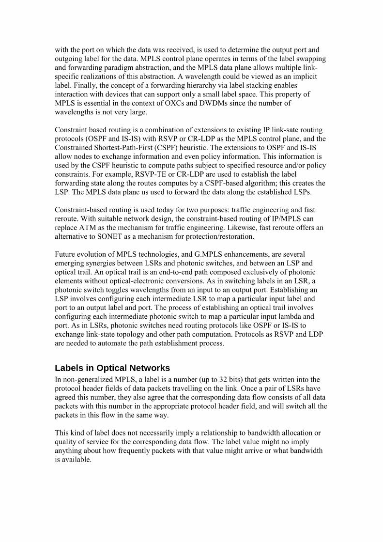
Link state protocols such as IS-IS and OSPF, allows all the nodes to dynamically coordinate a coherent up-to-date picture of the network graph, including the attributes of each edge or link (IP address, cost, bandwidth). This is referred as link sate database. Once the link state database is synchronized among all participating routes, each router uses the database to construct its own forwarding table. When a packet arrives at a router, the forwarding table is the consulted to determine how to forward the packet. If a link changes, the link state database must be resynchronized, and all routers recalculate their forwarding tables.
Figure: GMPLS Switched interface hierarchy
LSP Hierarchy Considering an LSP as a link in the IS-IS or OSPF link state database, LSPs can be nested inside other LSPs, rising to a hierarchy of LSPs. MPLS LSPs that enter the optical transport domain at the same node and leave the domain at the same node may be aggregated and tunneled within a single optical LSP. This aggregation helps to conserve the number of lambdas used by the MPLS domain. LSP hierarchy helps deal with the discrete nature of optical bandwidth. When an optical LSP is set up, it gets a discrete bandwidth (2,488 Gb/s). When this optical LSP is treated as a link, that link´s bandwidth need no longer be discrete. A 100Mbps MPLS LSP that
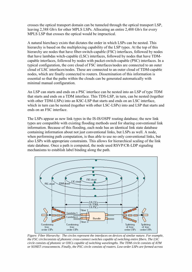
crosses the optical transport domain can be tunneled through the optical transport LSP, leaving 2,388 Gb/s for other MPLS LSPs. Allocating an entire 2,488 Gb/s for every MPLS LSP that crosses the optical would be impractical. A natural hierchacy exists that dictates the order in which LSPs can be nested. This hierarchy is based on the multiplexing capability of the LSP types. At the top of this hierarchy are nodes that have fiber-switch-capable (FSC) interfaces, followed by nodes that have lambdas witch-capable (LSC) interfaces, followed by nodes that have TDM-capable interfaces, followed by nodes with packet-switch-capable (PSC) interfaces. In a typical configuration, the core cloud of FSC interfaces/nodes are connected to an outer cloud of LSC interfaces/nodes. These are connected to an outer cloud of TDM-capable nodes, which are finally connected to routers. Dissemination of this information is essential so that the paths within the clouds can be generated automatically with minimal manual configuration. An LSP can starts and ends on a PSC interface can be nested into an LSP of type TDM that starts and ends on a TDM interface. This TDS-LSP, in turn, can be nested (together with other TDM-LSPs) into an KSC-LSP that starts and ends on an LSC interface, which in turn can be nested (together with other LSC-LSPs) into and LSP that starts and ends on an FSC interface. The LSPs appear as new link types in the IS-IS/OSPF routing database; the new link types are compatible with existing flooding methods used for sharing conventional link information. Because of this flooding, each node has an identical link state database containing information about not just conventional links, but LSPs as well. A node, when performing path computation, is thus able to use no only conventional links, but also LSPs with appropriate constraints. This allows for hierarchical scaling of the link state database. Once a path is computed, the node used RSVP/CR-LDP signaling mechanisms to establish label binding along the path.
Figure: Fiber Hierarchy: The circles represent the interfaces on devices of similar nature. For example, the FSC circleconsists of photonic cross-connect switches capable of switching entire fibers. The LSC circle consists of photonic or OXCs capable of switching wavelengths. The TDM circle consists of ATM or SONET crossconnects. Finally, the PSC circle consists of routers. Low-order LSPs are formed across
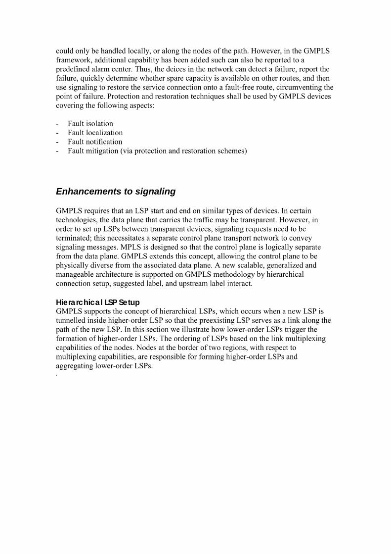
the cloud of higher-order interfaces and announced into the IGP. This allows low-order LSPs to be grouped together and hierarchically tunnelled through higher-order LSPs. Multiple PSC-LSPs are tunnelled within a TDM-LSP, multiple TDM-LSPs are grouped and tunnelled within an LSC-LSP, and so on. At the other end of the cloud they are split appropriately.
Link Bundling The link state database consists of all the nodes and links in a network, along with the attributes of each link. The links state database for an optical networks can easily be several orders of magnitude bigger than that for an MPLS network. To address this issuer, we aggregate the link attributes of several parallel links of similar characteristics, and assign these aggregated attributes to a single “bundled” link. In so doing, the size of the link state database is reduced by a large factor, leading to vastly improved scaling of the link state protocol. By summarizing, the attributed of several links into one bundled link, some information is lost; for example, with a bundle of SONET links the switching capability of the link interfaces (OC-12, OC-48, OC-192) are flooded; however, the number of such interfaces and the exact time slots used are not announced. However, the benefit of improved scalability will significantly outweigh the value of the information lost. In addition, while the link state protocol carries a single bundled link, signaling requires that individual component links be identified. LMP offers a means to accomplish this. All the links in an MPLS networks are typically assigned IP addresses. When a path is computed through the network, the links that constitute the path are identified by their IP addresses; this information is conveyed to the signaling protocol, which then sets up the path. Thus, it would seem that every link must have an IP address. However, this is not always easy. Unnumbered links are used to resolve this problem; anyhow, if an IP address is not used to identify a link, an alternative must substituted. What is required is a unique means of identifying links in a network; the task may be broken down into two steps. First, a mechanism is required to uniquely identify each node in the network; then each link emanating from that node is identified. Each node in the network is identified by a unique router ID; what remains is the latter problem of identifying the links emanating form a particular node. A solution to this problem, and the information that needs to be flooded by the routing protocols (OSPF and IS-IS) and that which needs to be communicated by the use of the signaling protocols can be … Each network node numbers its interfaces locally having the tuple [router ID, link number] that serves as the identification for a link. The reduction of management effort in configuring IP addresses, tracking allocated IP addresses, and dealing with the occasional duplicate address allocation is a significant saving, especially in a the context of optical networks with their large number of links.
Link Management protocol (LMP) A consequence of generalizing MPLS to encompass non-PSC links is that a label is no longer an abstract identifier, but must now be able to map to time slots, wavelengths, and physical resources such as the ports of a switch. This requires that the association of these physical labels be created between adjacent nodes. For IGP scaling purposes,
multiple links between nodes may be combined into a single bundled link. LMP runs between adjacent nodes and is used for both link provisioning and fault isolation. A key service provided by LMP is the associations between neighboring nodes for the component link Ids that may in turn be used as labels for physical resources. Within a bundled link, the component links and associated control channel need not be transmitted over the same physical medium. LMP allows for decoupling of the control channel from the component links. For example, the control channel could be transmitted along a separate wavelength or fiber, or over a separate Ethernet link between the two nodes. LMP is designed to provide four basic functions for a node pair: control channel management, link connectivity verification, link property correlation, and fault isolation.
� Control Channel Management is used to establish and maintain connectivity between adjacent nodes, and consists of a lightweight keep-alive Hello protocol that is transmitted over the control channel.
� Link Verification procedure is used to verify the physical connectivity of the component links, which is paramount due to correlation function of link properties between adjacent nodes. This is done when a link is first brought up and may be repeated any time a link is up and not in the verification procedure.
� Link Property Correlation is the mechanism to isolate link and channel failures in both opaque and transparent networks, independent of the data format. It is the confirmation between neighboring nodes that the mappings between local and remote interface IDs, and the aggregation of multiple data links into Traffic Engineering (TE) links are consistent.
� Fault management, as light paths typically traverse multiple data links going from ingress to egress. When this light path fails, LMP provides a way to localize which data link has failed.
� Authentication that provides cryptographic confirmation of the identity of the neighboring node.
Signaling Techniques The development of GMPLS necessitates enhancements to existing IP signaling and routing protocols. Two IP protocols, RSVP and LDP, are used to support GMPLS. One of the aspects of MPLS is the addition of a new connectivity abstraction: explicitly routed point-to-point path. This is accomplished by the concept of explicitly routed label switched paths (LSPs). This connectivity abstraction enables support for constraint-based routing, foundation for GMPLS. MPLS is based on the following concepts: - Separation of forwarding information (label) from the content of the IP header - Use of a single forwarding paradigm (label swapping) at the data plane to support
multiple routing paradigms at the control plane
- Use of different technologies and link layer mechanisms to realize the label swapping forwarding paradigm
- Flexibility in the formation of forwarding equivalence classes (FECs) - The concept of forwarding hierarchy via label stacking One application of MPLS is constraint-based routing, which is used to compute paths that satisfy various requirements subject to a set of constraints. Constraints-based routing is employed for two main purposes in contemporary networks: traffic engineering and fast reroute; future applications include diversity routing, which is the process by which disjoint paths are computed for protection purposes. One of the merits of MPLS is that it allows the elimination of redundant network layers by migrating some of the functions provided by ATM and SONET/SDH layers to the IP/MPLS control plane. With MPLS constraint-based routing the extensions to Open Shortest Path first (OSPF) and Intermediate System to Intermediate System (IS-IS) allow nodes to exchange information not just about network topology, but also about resource availability and administrative constraints. This information is used as input to a constraint-based path computation algorithm that computes paths subject to topology, resource, and administrative constraints. After computation of and appropriate path, a signaling protocol such as Resource Reservation Protocol with Traffic Engineering (RSVP-TE) or Constraint-Based Routing Label Distribution Protocol (CR-LDP) is then used to instantiate a label forwarding state along the path. Recent work has been done to extend and adapt the MPLS control plane, and specifically MPLS constraint-based routing, so that it can be used not just with routers and ATM switches, but also with optical crossconnects (OXCs). This is a fundamental step in the evolution and integration of data and optical network architectures. Developing a common control plane by reusing and extending existing routing and signaling protocols avoids the need to “reinvent the wheel”, thus minimizing risks associated with protocol development and reducing the time to market for advanced optical switching equipment. The protocol extensions are being standardized by the Internet Engineering Task Force (IETF) under the framework of generalized MPLS (GMPLS): - Enhancements to the RSVP-TE and CR-LDP signaling protocols to allow the
signaling and instantiation of optical channel trails in optical transport networks and other connection-oriented networking environments
- Enhancements to OSPF and IS-IS interior gateway routing protocols (IGPs) to advertise availability of optical resources in the network and other network attributes and constraints
- A new link management protocol, LMP, designed to address the issues related to link management in optical networks
Additional functionality has been added to GMPLS to address some limitations of the MPLS control plane, such as inability to establish bi-directional connections in a single request, and the absence of mechanisms to account for protection bandwidth so that it can be used for lower-priority traffic. Using the MPLS framework and its signaling protocols, a link or node failure along the routes of established service connections
could only be handled locally, or along the nodes of the path. However, in the GMPLS framework, additional capability has been added such can also be reported to a predefined alarm center. Thus, the deices in the network can detect a failure, report the failure, quickly determine whether spare capacity is available on other routes, and then use signaling to restore the service connection onto a fault-free route, circumventing the point of failure. Protection and restoration techniques shall be used by GMPLS devices covering the following aspects: - Fault isolation - Fault localization - Fault notification - Fault mitigation (via protection and restoration schemes)
Enhancements to signaling GMPLS requires that an LSP start and end on similar types of devices. In certain technologies, the data plane that carries the traffic may be transparent. However, in order to set up LSPs between transparent devices, signaling requests need to be terminated; this necessitates a separate control plane transport network to convey signaling messages. MPLS is designed so that the control plane is logically separate from the data plane. GMPLS extends this concept, allowing the control plane to be physically diverse from the associated data plane. A new scalable, generalized and manageable architecture is supported on GMPLS methodology by hierarchical connection setup, suggested label, and upstream label interact. Hierarchical LSP Setup GMPLS supports the concept of hierarchical LSPs, which occurs when a new LSP is tunnelled inside higher-order LSP so that the preexisting LSP serves as a link along the path of the new LSP. In this section we illustrate how lower-order LSPs trigger the formation of higher-order LSPs. The ordering of LSPs based on the link multiplexing capabilities of the nodes. Nodes at the border of two regions, with respect to multiplexing capabilities, are responsible for forming higher-order LSPs and aggregating lower-order LSPs. .
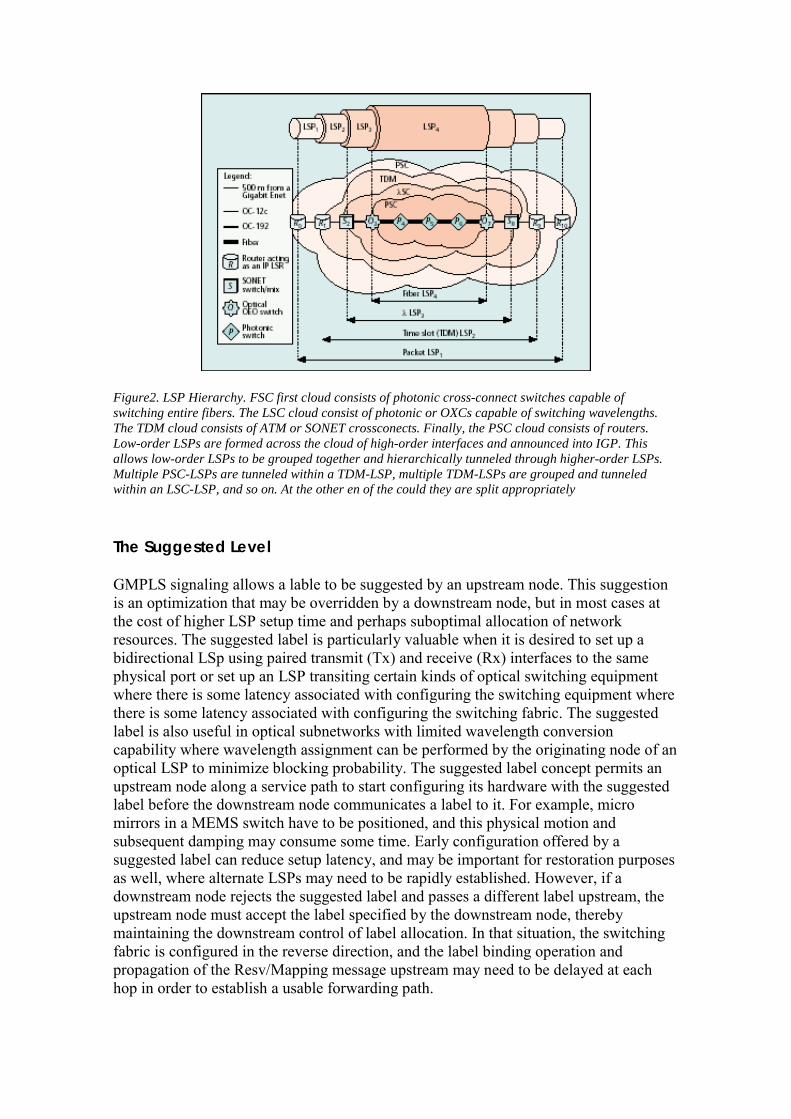
Figure2. LSP Hierarchy. FSC first cloud consists of photonic cross-connect switches capable of switching entire fibers. The LSC cloud consist of photonic or OXCs capable of switching wavelengths. The TDM cloud consists of ATM or SONET crossconects. Finally, the PSC cloud consists of routers. Low-order LSPs are formed across the cloud of high-order interfaces and announced into IGP. This allows low-order LSPs to be grouped together and hierarchically tunneled through higher-order LSPs. Multiple PSC-LSPs are tunneled within a TDM-LSP, multiple TDM-LSPs are grouped and tunneled within an LSC-LSP, and so on. At the other en of the could they are split appropriately The Suggested Level GMPLS signaling allows a lable to be suggested by an upstream node. This suggestion is an optimization that may be overridden by a downstream node, but in most cases at the cost of higher LSP setup time and perhaps suboptimal allocation of network resources. The suggested label is particularly valuable when it is desired to set up a bidirectional LSp using paired transmit (Tx) and receive (Rx) interfaces to the same physical port or set up an LSP transiting certain kinds of optical switching equipment where there is some latency associated with configuring the switching equipment where there is some latency associated with configuring the switching fabric. The suggested label is also useful in optical subnetworks with limited wavelength conversion capability where wavelength assignment can be performed by the originating node of an optical LSP to minimize blocking probability. The suggested label concept permits an upstream node along a service path to start configuring its hardware with the suggested label before the downstream node communicates a label to it. For example, micro mirrors in a MEMS switch have to be positioned, and this physical motion and subsequent damping may consume some time. Early configuration offered by a suggested label can reduce setup latency, and may be important for restoration purposes as well, where alternate LSPs may need to be rapidly established. However, if a downstream node rejects the suggested label and passes a different label upstream, the upstream node must accept the label specified by the downstream node, thereby maintaining the downstream control of label allocation. In that situation, the switching fabric is configured in the reverse direction, and the label binding operation and propagation of the Resv/Mapping message upstream may need to be delayed at each hop in order to establish a usable forwarding path.
Bidirectional LSP Setup Bidirectional optical LSPs (or lightpaths) are a requirement for many optical networking service providers. Both directions of an LSPs have the same traffic engineering requirements, including fate sharing, protection and restoration, and resource requirements (latency and jitter). A bidirectional LSP is only one initiator, node that starts the establishment of an LSP, and one terminator, LSP destination node. In a basic MPLS architecture, LSPs are unidirectional, so in order to establish a bidirectional LSP, two unidirectional LSPs in opposite directions must be established independently. This carries the following disadvantages:
o The latency to establish bidirectional LSP is a round-trip signalling time plus one initiator-terminator signaling transit delay.
o The control overhead is twice that of a unidirectional LSP, as control messages must be generated for both segments of the bidirectional LSP.
o Resources are established in separate segments, route selection can be quite complicated, this decreases the overall probability of successful establishment of the bidirectional connection.
o Existing SONET equipments transmits control information in-band using overhead bytes. Connections should remained paired and bidirectional establishment is highly desirable in this case.
Additional methods have been defined to allow bidirectional LSPs downstream and upstream data paths to be established using a single set of Path/Request and Resv/Mapping messages. This reduces the setup latency to essentially one initiator-terminator round-trip time plus processing time, and limits the control overhead o the same number of messages as a unidirectional LSP.
Figure: Bidirectional LSP setup
Notify Messages For network reliability one key requirement is a quick reaction and decisions made intelligently to network failures. As part of failure notification, a node passing transit connections should be able to notify the node responsible for restoring the connections when failures occur, without intermediate nodes processing the messages or modifying the state of the affected connections, avoiding unnecessary message processing at intermediate nodes that may delay the notification. The Notify message has been added
to RSVP-TE for GMPLS to provide the mechanism for informing nonadjacent nodes of LSP-related failures; similar mechanism has not been defined for CR-LDP. The Notify message does not replace existing RSVP error messages; however, it differs from them in that it can be ‘targeted’ to any node other than the immediate upstream or downstream neighbour. An important application for the nonadjacent Notify message is to notify when the control plane of a link has failed but the data plane (LSP) is still functional; a link in this condition is referred to as a degraded link. This way GMPLS control and data planes can be physically diverse and fail independently.
GMPLS Protection and Restoration Techniques At connection level, fault management consists of: - Detection - Localization - Notification - Mitigation Fault detection should be handled at the layer closest to the failure. One measure of fault detection at the physical layer is detecting loss of light (LOL); other techniques based on optical signal-to-noise ratio (OSNR), optically measured bit error rate (VER), dispersion, crosstalk, and attenuation are still being developed. Fault localization requires communication between nodes to determine where the failure has occurred. The consequence to using LOL to detect failures is that LOL propagates downstream along the connection’s path, and therefore all downstream nodes may detect the failure. The link Management Protocol (LMP) includes a fault localization procedure designed to localize failures in both transparent (all-optical) and opaque (optoelectrical) networks. Once the failure has been detected and localized, protection and restoration are used to mitigate the failure. The distinction between protection and restoration is centered on the different time scales in which they operate. Protection requires preallocated resource. Restoration, relies on dynamic resource establishment, and it may take up to an order of magnitude longer to restore the connection than protection switching. Restoration may also involve dynamic route calculation, which can be computationally expensive if the backup paths are not precalculated resources are no longer available. For example, SONET automatic protection switching (APS) is designed to switch traffic from a primary path to a secondary path in less than 50ms, requiring simultaneous transmission along both a primary and a secondary path (1+1 protection). Restoration relies on dynamic resource establishment, and it may take up to an order of magnitude longer to restore the connection than protection switching. Restoration is designed to react to failures quickly and use bandwidth efficiently, but typically involves dynamic resource establishment and route calculation, and therefore takes more time to switch to an alternate path protection techniques. Restoration can be implemented at the source or an intermediate node once the responsible node has been notified. Failure notification is done using the notify procedures discussed earlier, or using standard error messages.
Protection and restoration have traditionally been addressed using two techniques: path switching and line switching. In path switching, the failure is addressed at the path endpoints whereas in line switching the failure is addressed at the transit node where the failure is detected. Path switching can be further subdivided into:
� path protection, where secondary protection paths are preallocated � path restoration, where connections are rerouted, either dynamically or using
precalculated paths. Line switching is divided into:
� span protections, where traffic is switched to an alternate parallel channel or link connecting the same two nodes
� line restoration, where traffic is switched to an alternate route between the two nodes
To effectively use protection, there must mechanism to:
o Distribute relevant link properties, such as protection bandwidth and protection capabilities
o Establish secondary paths through the network o Signal switch from the primary path to secondary paths and back
The signaling capabilities of GMPLS will allow service providers to quickly build out high-capacity agile infrastructures that support fast provisioning of connection services. Now that demand for data transport has eclipsed that for voice, it is approximate that the control plane mechanism expand to embrace data transport more closely while still serving the incumbent needs of voice transport. Service providers can incrementally deploy GMPLS-based products in existing networks to decrease costs without impacting service quality. Furthermore protection and restoration capabilities of GMPLS allow efficient addressing of network survivability, while opening the door to new types of services. in any solution that aims to enable large volumes of traffic in a cost-efficient manner for service providers.
MPLS Traffic Engineering Control with Optical Crossconnects Combination of recent advances in MPLS traffic engineering control plane with OXC technology to provide a framework for real-time provisioning of optical channels gives the development and deployment of a new class of OXCs, and allow the use of uniform semantics for network management and operations control in hybrid networks consisting of OXCs and label switching routers. The proposed approach is particularly advantageous for OXCs intended for data centric optical internetworking systems. A new class of OXCs that address the optical transport needs of the Internet will assist in optical channel layer bandwidth management, dynamic provisioning of optical
channels, and network survivability through enhanced protection and restoration capabilities. OXC is a path switching element in an optical transport network that establishes routed paths for optical channels by locally connecting an optical channel from an input port (fiber) to an output port (fiber) on the switch element. The proposed OXC control plane uses the Internal Gateway Protocol (IGP) extensions for MPLS traffic engineering (with additional enhancements) to distribute relevant optical transport network state information, including topology state information. This state information is subsequently used by a constraint-based routing system to compute paths for point-to-point optical channels. The proposed OXC control plane also uses an MPLS signaling protocol to instantiate point-to-point optical channels. The combination of MPLS Traffic engineering Control with OXC has the following advantages:
� A framework for optical bandwidth management and the real-time provisioning of optical channels
� Exploits recent advantages in MPLS control plane technology and also leverages accumulated operational experience with IP distributed routing control
� No need new class of control protocols for optical transport, allowing the reuse of software developed for MPLS traffic engineering application. Consequently it fosters the rapid development and deployment of a new class of OXCs.
� Introduction of control coordination concepts between data network elements and optical network elements.
� Simplification of network administration in facilities-based service provider networks by providing uniform semantics for network management and control in both the data and optical domains.
� Way open for the eventual introduction of DWDM multiplexing capabilities on IP routers.
� Preliminary framework for the notion of an optical Internet.
The growth, performance, and survivability requirements of the Internet are mandating IP-centric networks to be cost effective, survivable, and scalable, and to provide control capabilities that facilitate network performance optimization. Some of these requirements are being addressed by the multiprotocol label switching (MPLS) traffic engineering capabilities under development by the Internet Engineering Task Force (IETF).
The underlying optical transport network also needs to be versatile, reconfigurable, and cost effective, and to support a variety of protection and restoration capabilities due to the rapidly changing requirements of the Internet.
A results of these trends is the evolution of optical transport networks from simple linear and ring topologies to (partial) mesh topologies.
The ITU-T Recommendation G.872 speaks about of an optical transport network (OTN) as “a transport network bounded by optical channel access points”. It is based on a layered structure, which includes:
� An optical channel layer network (OCh) � An optical multiplex section layer network � An optical transmission section layer network
The OCh layer network supports end-to-end networking of optical channel trails between access points. The OCh layer network provides the following functions: routing, monitoring, grooming, and protection and restoration of optical channels. In this situation, programmable OXCs will be critical to the realization of the OCh layer functions, especially in mesh optical networks. There are other standards organizations and interoperability forums developing projects related to dynamically reconfigurable optical networks as ANSI T1X1.5 committee, the Optical Internetworking Forum (OIF), and the IETF. The successful realization of the versatile optical networking depends on the synthesis of appropriate control plane technologies with programmable and reconfigurable OXCs.
OXCs, LSRs, Optical Trails and Explicit LSPs Let´s consider a hybrid IP-centric optical internet-working environment consisting of label switching routers (LSRs) and OXCs, where the OXCs are programmable and support wavelength conversion/translation. The data plane of LSR performs label swapping to transfer labeled packet from an input port to an output port. The data plane of an OXC uses a switching matrix to connect an OCh trail from an input port to an output port. An LSR performs label switching by first establishing a relation between an <input port, input label> tuple and an <output port, output label> tuple. Likewise, an OXC provisions OCh trails by first establishing a relation between an <input port, input optical channel> tuple and an <output port, output optical channel> tuple. These relations are determined by the control plane of the respective network elements, and are locally instantiated on the device through a switch controller. The functions of the control plane (for both LSRs and OXCs) include resource discovery, distributed routing control, and connection management. In particular, the control plane of the LSR is used to discover, distribute, and maintain relevant state information associated with the MPLS traffic engineering rules and policies. An LSP is the path through one or more LSRs followed by a specific forwarding equivalence class. An explicit LSP is one whose route is defined as its origination node. The control plane of the OXC is used to discover, distribute, and maintain relevant state information associated with the OTN, and to establish and maintain OCh trails under various optical traffic engineering rules and policies. An OCh trail provides a point-to-point optical connection between two access points. At each intermediate OXC along the route of an OCh trail, the OXC switch fabric connects the trail from an input port to an output port. A distinction between OXCs and LSRs is that the former do not perform packet-level processing in the data plane, while the latter are datagram devices which may perform

certain packet-level operations in the data plane. A significant conceptual difference is that with LSRs the forwarding information is carried explicitly as part of the labels appended to data packets, while with OXCs the switching information is implied from the wavelength or optical channel.
Explicit LSPs and Optical Channel Trails At a conceptual level, explicit LSPs and optical channel trails exhibit certain commonalities. Both are unidirectional point-to-point path connection abstraction. An explicit LSP provides parameterized packet forwarding path (traffic trunck) between an ingress LSR and egress LSR. Correspondingly, an OCh trail provides a OCh between tow endpoits for the transport of client digital signals. The payload carried by both LSPs and optical trails are transparent to intermediate nodes along their respective paths. Both LSPs and optical trails can be parameterized to stipulate their performance, behavioral, and survivability requirements from the network. A constraint-based routing scheme can be used to select appropriate paths for both LSPs and optical trails. Generally, such paths may satisfy some demands and policy requirements subject to some constraints imposed by the operational environment.
Generic Requirements for the OXC Control Plane The requirements for the OXC control plane include three key aspects:
� Capability to establish OCh trails expeditiously (in seconds or milliseconds) � Capability to support traffic engineering functions. The introduction of DWDM
(Dense Wavelength Division Multiplex) and automatically switched networks is unlikely to eliminated the need for traffic engineering. Instead, it will simply mandate OXCs to also support some traffic engineering capabilities.
� Capability to support various protection and restoration schemes. The control plane of OTN till now has been implemented via network management with the following drawbacks:
� Slow convergence following failure events: the only way to expedite service recovery in such environments is to preprovision dedicated protection channels
� Complex task of interworking equipment from different manufacturers, especially at the management level.
� Complex task of internetwork provisioning (due to the lack of EDI between operator NMSs)
� Such environments do not permit the use of distributed dynamic routing control capabilities.
Another important motivation for the approach of OXC with MPLS traffic engineering, is the improvement of the responsiveness of the optical transport network, and the increase of the level of interoperability within and between services provider networks.
MPLS Traffic Engineering as Generic Control Plane for OXCs The MPLS traffic engineering control plane is a synthesis of new concepts in IP traffic engineering and the conventional IP network layer control plane. The MPLS traffic engineering control plane includes the following components:
� Resource discovery � State information dissemination: distribution of the relevant information
concerning the state of the network, including topology and resource availability information.
� Path selection: used to select an appropriate route through the MPLS network for explicit routing and implemented by introducing constraint-based routing (computation of the paths that satisfy certain specifications subject to certain constraints imposed by the environment).
� Path management: label distribution, path placement, path maintenance, and path revocation. Implemented thanks to RSVP extensions or CR-LDP.
The components of the MPLS traffic engineering control plane are separable and independent of each other. In several new MPLS control plane capabilities were proposed various traffic engineering policies to be actualized in MPLS. Many of these capabilities are also relevant and applicable to OTNs with reconfigurable OXCs. A traffic trunk is an aggregation of traffic belonging to the same class that is forwarded through a common path. In general, the traffic trunk is technology independent abstraction and used within the context of MPLS and allowed certain attributes of the traffic transported through LSPs to be parameterized. The traffic trunk concept can also be extended to the OTN. The attributes associated with traffic trunks include:
� Traffic parameters which indicate bandwidth requirements of the traffic trunk � Adaptively attributes, which specify the sensitivity of the traffic trunk to
changes in the state of the network and indicates whether the traffic trunk can be rerouted when better paths become available.
� Priority attributes, for a partial order on the set of traffic trunks, allowing path selection and path placement operations to be prioritized.
� Preemption attributes which indicate whether a traffic trunk can preempt an existing traffic trunk in its path.
� Resilience attributes, which stipulate the survivability requirements of the traffic trunk and the response of the system to faults that impact the path of the traffic trunk.
� Resource class affinity attributes, which further restrict route selection to specific subsets of resources and allow generalized inclusion and exclusion policies to be implemented.
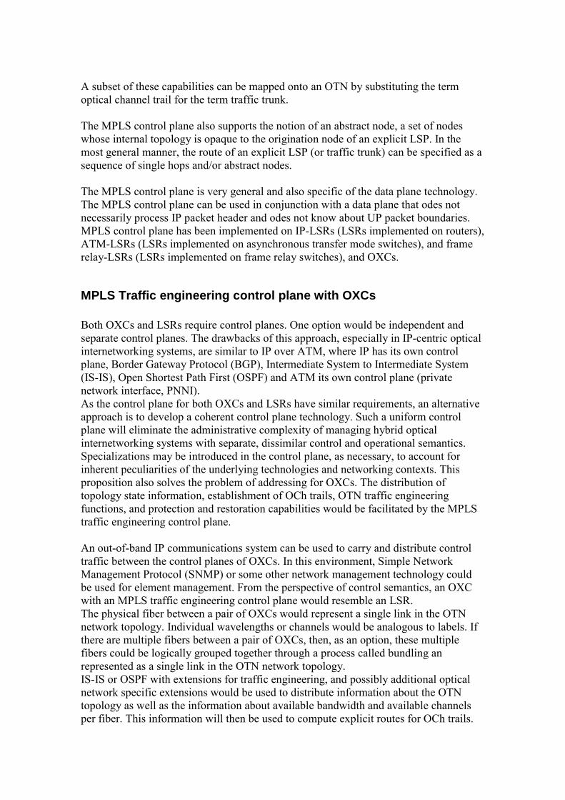
A subset of these capabilities can be mapped onto an OTN by substituting the term optical channel trail for the term traffic trunk. The MPLS control plane also supports the notion of an abstract node, a set of nodes whose internal topology is opaque to the origination node of an explicit LSP. In the most general manner, the route of an explicit LSP (or traffic trunk) can be specified as a sequence of single hops and/or abstract nodes. The MPLS control plane is very general and also specific of the data plane technology. The MPLS control plane can be used in conjunction with a data plane that odes not necessarily process IP packet header and odes not know about UP packet boundaries. MPLS control plane has been implemented on IP-LSRs (LSRs implemented on routers), ATM-LSRs (LSRs implemented on asynchronous transfer mode switches), and frame relay-LSRs (LSRs implemented on frame relay switches), and OXCs.
MPLS Traffic engineering control plane with OXCs Both OXCs and LSRs require control planes. One option would be independent and separate control planes. The drawbacks of this approach, especially in IP-centric optical internetworking systems, are similar to IP over ATM, where IP has its own control plane, Border Gateway Protocol (BGP), Intermediate System to Intermediate System (IS-IS), Open Shortest Path First (OSPF) and ATM its own control plane (private network interface, PNNI). As the control plane for both OXCs and LSRs have similar requirements, an alternative approach is to develop a coherent control plane technology. Such a uniform control plane will eliminate the administrative complexity of managing hybrid optical internetworking systems with separate, dissimilar control and operational semantics. Specializations may be introduced in the control plane, as necessary, to account for inherent peculiarities of the underlying technologies and networking contexts. This proposition also solves the problem of addressing for OXCs. The distribution of topology state information, establishment of OCh trails, OTN traffic engineering functions, and protection and restoration capabilities would be facilitated by the MPLS traffic engineering control plane. An out-of-band IP communications system can be used to carry and distribute control traffic between the control planes of OXCs. In this environment, Simple Network Management Protocol (SNMP) or some other network management technology could be used for element management. From the perspective of control semantics, an OXC with an MPLS traffic engineering control plane would resemble an LSR. The physical fiber between a pair of OXCs would represent a single link in the OTN network topology. Individual wavelengths or channels would be analogous to labels. If there are multiple fibers between a pair of OXCs, then, as an option, these multiple fibers could be logically grouped together through a process called bundling an represented as a single link in the OTN network topology. IS-IS or OSPF with extensions for traffic engineering, and possibly additional optical network specific extensions would be used to distribute information about the OTN topology as well as the information about available bandwidth and available channels per fiber. This information will then be used to compute explicit routes for OCh trails.
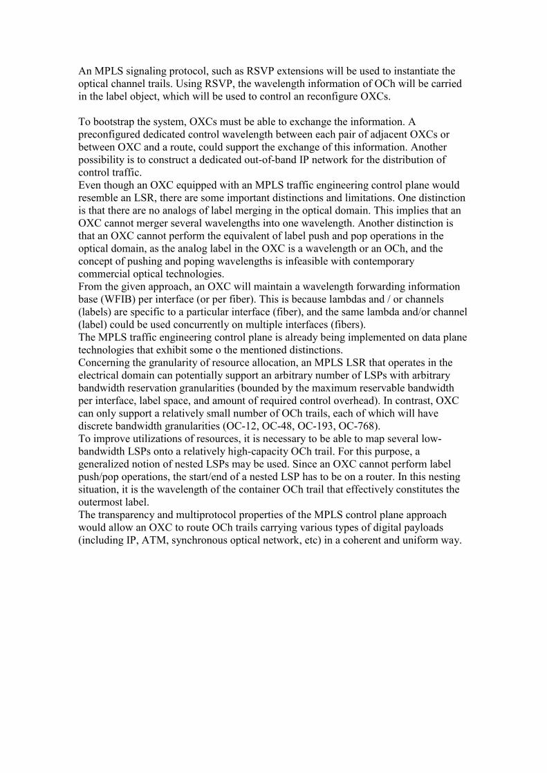
An MPLS signaling protocol, such as RSVP extensions will be used to instantiate the optical channel trails. Using RSVP, the wavelength information of OCh will be carried in the label object, which will be used to control an reconfigure OXCs. To bootstrap the system, OXCs must be able to exchange the information. A preconfigured dedicated control wavelength between each pair of adjacent OXCs or between OXC and a route, could support the exchange of this information. Another possibility is to construct a dedicated out-of-band IP network for the distribution of control traffic. Even though an OXC equipped with an MPLS traffic engineering control plane would resemble an LSR, there are some important distinctions and limitations. One distinction is that there are no analogs of label merging in the optical domain. This implies that an OXC cannot merger several wavelengths into one wavelength. Another distinction is that an OXC cannot perform the equivalent of label push and pop operations in the optical domain, as the analog label in the OXC is a wavelength or an OCh, and the concept of pushing and poping wavelengths is infeasible with contemporary commercial optical technologies. From the given approach, an OXC will maintain a wavelength forwarding information base (WFIB) per interface (or per fiber). This is because lambdas and / or channels (labels) are specific to a particular interface (fiber), and the same lambda and/or channel (label) could be used concurrently on multiple interfaces (fibers). The MPLS traffic engineering control plane is already being implemented on data plane technologies that exhibit some o the mentioned distinctions. Concerning the granularity of resource allocation, an MPLS LSR that operates in the electrical domain can potentially support an arbitrary number of LSPs with arbitrary bandwidth reservation granularities (bounded by the maximum reservable bandwidth per interface, label space, and amount of required control overhead). In contrast, OXC can only support a relatively small number of OCh trails, each of which will have discrete bandwidth granularities (OC-12, OC-48, OC-193, OC-768). To improve utilizations of resources, it is necessary to be able to map several low-bandwidth LSPs onto a relatively high-capacity OCh trail. For this purpose, a generalized notion of nested LSPs may be used. Since an OXC cannot perform label push/pop operations, the start/end of a nested LSP has to be on a router. In this nesting situation, it is the wavelength of the container OCh trail that effectively constitutes the outermost label. The transparency and multiprotocol properties of the MPLS control plane approach would allow an OXC to route OCh trails carrying various types of digital payloads (including IP, ATM, synchronous optical network, etc) in a coherent and uniform way.
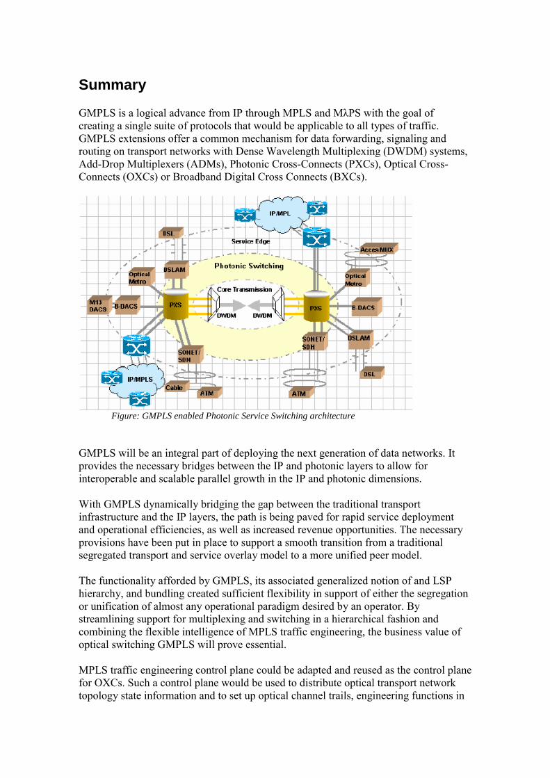
Summary GMPLS is a logical advance from IP through MPLS and MλPS with the goal of creating a single suite of protocols that would be applicable to all types of traffic. GMPLS extensions offer a common mechanism for data forwarding, signaling and routing on transport networks with Dense Wavelength Multiplexing (DWDM) systems, Add-Drop Multiplexers (ADMs), Photonic Cross-Connects (PXCs), Optical Cross-Connects (OXCs) or Broadband Digital Cross Connects (BXCs).
Figure: GMPLS enabled Photonic Service Switching architecture
GMPLS will be an integral part of deploying the next generation of data networks. It provides the necessary bridges between the IP and photonic layers to allow for interoperable and scalable parallel growth in the IP and photonic dimensions. With GMPLS dynamically bridging the gap between the traditional transport infrastructure and the IP layers, the path is being paved for rapid service deployment and operational efficiencies, as well as increased revenue opportunities. The necessary provisions have been put in place to support a smooth transition from a traditional segregated transport and service overlay model to a more unified peer model. The functionality afforded by GMPLS, its associated generalized notion of and LSP hierarchy, and bundling created sufficient flexibility in support of either the segregation or unification of almost any operational paradigm desired by an operator. By streamlining support for multiplexing and switching in a hierarchical fashion and combining the flexible intelligence of MPLS traffic engineering, the business value of optical switching GMPLS will prove essential. MPLS traffic engineering control plane could be adapted and reused as the control plane for OXCs. Such a control plane would be used to distribute optical transport network topology state information and to set up optical channel trails, engineering functions in
the optical domain, and enable a variety of protection and restoration capabilities. Furthermore, such a control plane technology would expedite the development and deployment of a new class of datacentric OXCs. A simply integration of OXCs and LSRs would provide coherent semantics for network management and operations control in hybrid optical internetworking systems consisting of LSRs and OXCs. A key benefit of GMPLS is that it allows network operators increased freedom to design their networks to best meet their specific objectives. G-MPLS can be used with traditional overlay network architectures, where each traffic type is managed through its own control plane. However, the great potential of G-MPLS is that it makes possible the evolution to peer-based networks in which all network elements have full information about all other elements. The most efficient choice for building such networks is through deployment of network elements capable of carrying packet, TDM and wavelength traffic along with an element and network management system design to manage multiple layers of an intelligent network consolidated onto the G-MPLS control plane. By consolidating different traffic types GMPLS permits simplification of networks and improves their scalability. Optical networking is an important and challenging domain for development and experimentation using GMPLS protocols. Conversely, use of GMPLS and LMP is a major step forward for optical network providers who have historically been troubled by interoperability problems resulting from non-standarized control and management protocols. The application of Generalized MPLS to optical network has thrown up a number of interesting technical challenges and some of them can already be addressed in practice.
Bibliografía •• ““ TThhee eevvoolluuttiioonn ttoowwaarrddss pphhoottoonniiccss nneettwwoorrkkiinngg:: ffrroomm SSDDHH//AATTMM//IIPP ttoo
MMPPLLSS//GG..MMPPLLSS””,, NNEETTTTEESSTT TTeecchhnniiccaall DDooccuummeennttaattiioonn,, AAllccaatteell SSeemmiinnaarryy •• ““IInntteerrnneett PPrroottooccooll ((IIPP)) IInntteerrnneettwwoorrkkiinngg TTrraannssppoorrtt””,, WWeebb PPrrooffoorruumm TTuuttoorriiaallss,,
wwwwww..iieecc..oorrgg •• ““OOppttiiccaall SSwwiittcchhiinngg nneettwwoorrkkss:: ffrroomm cciirrccuuiittss ttoo ppaacckkeettss””,, AA..HHiillll,, FF.. NNeerrii,, IIEEEEEE
CCoommmmuunniiccaattiioonnss MMaaggaazziinnee,, MMaarrcchh 22000011 •• ““MMuullttiipprroottooccooll LLaammbbddaa SSwwiittcchhiinngg CCoommbbiinniinngg MMPPLLSS TTrraaffffiicc EEnnggiinneeeerriinngg CCoonnttrrooll
wwiitthh OOppttiiccaall CCrroossssccoonnnneeccttss””,, IIEEEEEE CCoommmmuunniiccaattiioonnss MMaaggaazziinnee,, MMaarrcchh 22000011
•• ““GGeenneerraalliizzeedd MMuullttiipprroottooccooll LLaabbeell SSwwiittcchhiinngg:: AAnn OOvveerrvviieeww ooff RRoouuttiinngg aanndd MMaannaaggmmeenntt EEnnhhaanncceemmeennttss””,, IIEEEEEE CCoommmmuunniiccaattiioonnss MMaaggaazziinnee,, JJaann 22000011
•• ““GGeenneerraalliizzeedd MMuullttiipprroottooccooll LLaabbeell SSwwiittcchhiinngg:: AAnn OOvveerrvviieeww ooff SSiiggnnaalliinngg
EEnnhhaanncceemmeennttss aanndd RReeccoovveerryy TTeecchhnniiqquueess””,, IIEEEEEE CCoommmmuunniiccaattiioonnss MMaaggaazziinnee,, JJuullyy 22000011
•• www.gmpls.org •• www.cisco.org •• wwwwww..lluucceenntt..ccoomm ••