GL500 Main Unit Specifications GL400/GL350 Main Unit ... · 0≦Ts≦2315:±(0.2% of rdg +4℃)...
4
Basic Specifications GL500 Number of analog input terminal units 2 Sampling interval* 1 Current 1 ms - 1 h Event 2 μs (one channel) - 1 s Trigger functions Current Type: Start (Data Capture starts when a trigger is generated) Stop (Data Capture stops when a trigger is generated) Condition: Start: Level, Scheduled Time, External, Off Stop: Level, Scheduled Time, External, Elapsed Time, Event Full (two channels can be specified), Off Event Type: Start (Data Capture starts when a trigger is generated) Stop (Data Capture stops when a trigger is generated) Condition: Start: Level, External, Off Stop:Level, External, Off Alarm functions Type Analog, Logic, Pulse (AND and OR operations available) Condition Analog: H, L, Window In, Window Out Logic: 4-ch pattern Pulse: H, L, Window In, Window Out Pulse/Logic input Either Pulse or Logic can be selected. Number of channels: 4 Pulse input range Count mode 5 c, 50 c, 500 c, 5 kc, 50 kc/f.s. (max. 50k/sampling interval) Inst. mode 5 c, 50 c, 500 c, 5 kc, 50 kc/f.s. (max. 50 k/sampling interval) RPM mode 5 rpm, 50 rpm, 500 rpm, 5 krpm, 50 krpm/f.s. (max. 50k/sec) Alarm output Number of channels 4 ch Output format Open collector output (100 k Ωpull-up resistance) Output conditions Level judgment, Window judgment, Logic Pattern judgment, Pulse judgment External trigger input* 2 1 ch Internal memory Current: 4 MByte (2M words) Event: 32 MByte (16M words) PCMCIA slot Type 2 compatible Monitor Size 4.7-inch STN color LCD Displayed items Waveforms + digital values, waveforms only, digital values only Functions Expanded/compressed waveform displays, scaling, statistical calculations, four arithmetic operations, search Operating environment Temperature: 0 - 40° C, Humidity 30 - 80% RH Withstand voltage 1 minute at 500 Vp-p (between each input channel and main unit chassis) Power supply AC adapter (100 to 240 VAC, 50/60Hz) DC input (8.5 to 24 VDC) *3, battery pack * 3 Power consumption 26 VA or lower (AC drive) External dimensions (W x D x H, approx.) 212 x 162 x 45 mm Weight (approx.) 800g *4 Basic Specifications GL400 GL350 Number of analog input terminal units 2 Sampling interval * 1 100 ms (10 ch) - 1 h Trigger functions Type Start (Data Capture starts when a trigger is generated) Stop (Data Capture stops when a trigger is generated) Condition Start: Level, Alarm, External, Off Stop: Level, Alarm, External, Time Alarm functions Type Analog, Logic, Pulse (AND and OR operations available) Condition Analog: H, L, Window In, Window Out Logic: 4-ch pattern Pulse: H, L, Window In, Window Out Number of channels for logic input 4 ch Number of channels for pulse input 1 ch Pulse input range Count mode 50 kc, 500 kc, 5 Mc, 50 Mc, 500 Mc/f.s. (max. 50k/sampling interval) Inst. mode 50 kc, 500 kc, 5 Mc, 50 Mc/f.s. (max. 50 k/sampling interval) RPM mode 500 rpm, 5 krpm, 50 krpm, 500 krpm/f.s. (max. 50 k/sec) Alarm output Number of channels 4 ch Output format Open collector output (100 k Ωpull-up resistance) Output conditions Level judgment, Window judgment, Logic Pattern judgment, Pulse judgment External trigger input*2 1 ch Internal memory 4 MByte PCMCIA slot Type 2 compatible Monitor Size 4.7-inch STN color LCD Displayed items Waveforms + digital values, waveforms only, digital values only Functions Expanded/compressed waveform displays, scaling, statistical calculations, search Operating environment Temperature: 0 - 40° C, Humidity 30 - 80% RH Power supply AC adapter (100 to 240 VAC, 50/60Hz), DC input (8.5 to 24 VDC) * 3 , battery pack * 3 Power consumption External dimensions (W x D x H, approx.) 212 x 152 x 45mm 212 x 152 x 40mm Weight (approx.) 850g * 4 710g * 4 Item 4VF 4MF 8MS Number of input channels 4 4 8 Type of input terminal BNC Screw type terminal Screw type terminal Method Scan Scan Scan All channels isolated All channels isolated Channels not isolated Non-balanced input Non-balanced input Balanced input Measurement ranges Voltage ±100,500 mV ±100,500 mV ±100,500 mV ±1,5,10,50,100 V ±1,5,10,50,100 V ±1,5,10 V Temperature K, J, E, T, R, S, B, N, W K, J, E, T, R, S, B, N, W Type of input filter Type Line (1.5 Hz), 5 Hz, 50 Hz, 500 Hz Frequency response DC - 20 kHz (+1/-3 dB Typ) Voltage ±0.3 % of F.S. Temperature <TC-K、 J、 E> -200≦Ts≦0:±(1% of rdg +3.5℃) 0<Ts≦MAX:±(0.2% of rdg +3.5℃) <MAX> 1370(K)、 1100(J)、 800(E) <TC-T> -200≦Ts≦0:±(0.8% of rdg +3℃) 0<Ts≦400:±(0.2% of rdg +3℃) <TC-R、 S> 0≦Ts≦200:±9.5℃ 200<Ts≦800:±6.5℃ 800<Ts≦MAX:±(0.2% of rdg +4.5℃) <MAX> 1600(R)、 1760(S) <TC-B> 600≦Ts≦700:±9.5℃ 700<Ts≦1820:±(0.2% of rdg +5.5℃) <TC-N> 0≦Ts≦1300:±(0.2% of rdg +3.5℃) <TC-W> 0≦Ts≦2315:±(0.2% of rdg +4℃) (including the reference junction compensation accuracy) A/D converter 14 bit Maximum input voltage Between +/- 100 mV - 10 V range: 30 V 100 mV -10 V range: 10 V 50 V - 100 V range: 100 V AC33 Vr.m.s (60 VDC) Non-isolated Withstand voltage Between input terminal and GND Non-isolated 1 minute at 500 VAC Item 10SU 20SU 50SU Number of input channels 10 20 50 Type of input terminal Screw type terminal Method Scan All channels isolated, Non-balanced input Measurement ranges Voltage ±20, 50, 100, 200, 500 mv ±1, 2, 5, 10, 20, 50, 1-5 V Temperature Thermocouple: K, J, E, T, R, S, B, N, W Resistance thermometer bulb: Pt100, JPt100 Type of input filter Type On/Off Measurement precision Voltage ±0.1 % of F.S. Temperature *1 If the reference junction compensation is internal, add ±0.5 ℃to each of the following values. <Thermocouple: R, S > 0℃≦TS≦100 ℃: ±5.2 ℃ 100 ℃≦TS≦300 ℃: ±3.0 ℃ 300 ℃≦TS≦1760 ℃: ± (0.05 % of rdg + 2 ℃) <Thermocouple: B> 400 ℃≦TS≦600 ℃: ±3.5 ℃ 600 ℃<TS≦1820 ℃: ± (0.05 % of rdg + 2 ℃) <Thermocouple: K, E> -200 ℃≦TS≦-100 ℃: ± (0.05 % of rdg + 2 ℃) -100 ℃<TS≦MAX: ± (0.05 % of rdg + 1 ℃) (Max. K=1370, E=800, T=400) <Thermocouple: T> -200 ℃≦TS≦-100 ℃: ± (0.1 % of rdg + 1.5 ℃) -100 ℃≦TS≦400 ℃: ± (0.1 % of rdg + 0.5 ℃) <Thermocouple: J> -200 ℃≦TS≦-100 ℃: ±2.7 ℃ -100 ℃≦TS≦100 ℃: ±1.7 ℃ 100 ℃<TS≦1100 ℃: ± (0.05 % of rdg + 1 ℃) <Thermocouple: N> 0 ℃≦TS≦1300 ℃: ± (0.1 % of rdg + 1 ℃) <Thermocouple: W> 0 ℃≦TS≦2315 ℃: ± (0.1 % of rdg + 1.5 ℃) Resistance thermometer bulb Pt100: -200 ℃- 850 ℃: ±(0.05 % of rdg + 0.5 ℃) JPt100: -200 ℃- 500 ℃: Pt F.S.=1050 ℃, JPt F.S.=700 ℃ A/D converter 16 bit Maximum input voltage Between +/- 60 Vp-p 60 Vp-p Withstand voltage Between input terminal and GND 1 minute at 350 Vp-p GL500 Main Unit Specifications *1 The number of channels available may depend on the sampling speed. *2 Maximum input voltage: + 24 V, input threshold voltage: approx. +2.5V, hysteresis: approx. 1V (+2 to +3V) *3 Optional *4 GL500VF: excluding the battery and AC adapter" GL400/GL350 Main Unit Specifications *1 The number of channels available may depend on the sampling speed. *2 Maximum input voltage: + 24 V, input threshold voltage: approx. +2.5V, hysteresis: approx. 1V (+2 to +3V) *3 Optional *4 Excluding the battery and AC adapter" GL500 Terminal Unit Specifications GL400/350 Terminal Unit Specifications *1 Operating temperature: 23℃ ± 3℃. Values are those 30 minutes after power-on. Assuming that the terminal unit is in factory shipped condition (terminal unit 1 is used). The filter setting is ON. “rdg” means reading. When faster, higher performance measurements are required: For fastest 40MS/s speed measurements: DATA PLATFORM “DM3300”� Model with a high-speed isolated voltage amplifier and three plug-in amplifiers. High capacity memory For isolated 1MS/s long time measurements: DATA PLATFORM“DM3100V2”� Model with isolated plug-in amplifiers High capacity memory In addition to the industry-first 40MS/s HSV (high-speed voltage) amplifier, the M (voltage/temperature), DCB (distortion) and B-503 (logic) amplifiers are incorporated as standard 2MW/ch memory and PCMCIA drive are built in as standard. Optionally, a 40GB HDD can be installed. The V (voltage), M (voltage/temperature), DCB (distortion), FV (frequency) and B-503 (logic) amplifiers are incorporated. 2MW/ch memory and PCMCIA drive are built in as standard. Optionally, a 40GB HDD can be installed. SCN200409055000AS Printed in Japan 503-10 Shinano-cho, Totsuka-ku, Yokohama 244-8503, Japan Tel : +81-45-825-6250 Fax : +81-45-825-6396 Email : [email protected] http://www.graphteccorp.com Website Graphtec Corp Between input terminal/chassis Between input terminal/chassis 15 VA or lower (AC drive) 7.2 VA or lower (DC drive) 10 VA or lower (AC drive) 5.3 VA or lower (DC drive) Please contact the manufacturer of your PC for warranty and maintenance/replacement parts. Graphtec does not warrant any damage or loss of data arising from the failures of the main unit or PC. Please make sure to backup your data regularly The information in this catalog is accurate and complete as of January 24, 2005. The software and hardware names contained in this document are trademarks or registered trademarks of respective companies. Windows is trademark or registered trademark of Microsoft Corporation in the United State and other countries. The information in this catalog, such as specifications and prices, is subject to change without notice. Please be sure to visit our website and check the latest information before purchasing. Measurement precision* (23℃±3℃) 30 min after power-on Line filter: ON Data stored in current memory * Thermocouple diameters: T:0.32 φ , others: 0.65 φ
Transcript of GL500 Main Unit Specifications GL400/GL350 Main Unit ... · 0≦Ts≦2315:±(0.2% of rdg +4℃)...
Basic Specifications GL500Number of analog input terminal units 2Sampling interval*1 Current 1 ms - 1 h
Event 2μs (one channel) - 1 sTrigger functions Current Type: Start (Data Capture starts when a trigger is generated)
Stop (Data Capture stops when a trigger is generated)Condition: Start: Level, Scheduled Time, External, Off
Stop: Level, Scheduled Time, External, Elapsed Time, Event Full (two channels can be specified), Off
Event Type: Start (Data Capture starts when a trigger is generated)Stop (Data Capture stops when a trigger is generated)
Condition: Start: Level, External, Off Stop:Level, External, Off
Alarm functions Type Analog, Logic, Pulse (AND and OR operations available)Condition Analog: H, L, Window In, Window Out
Logic: 4-ch patternPulse: H, L, Window In, Window Out
Pulse/Logic input Either Pulse or Logic can be selected. Number of channels: 4 Pulse input range Count mode 5 c, 50 c, 500 c, 5 kc, 50 kc/f.s. (max. 50k/sampling interval)
Inst. mode 5 c, 50 c, 500 c, 5 kc, 50 kc/f.s. (max. 50 k/sampling interval)RPM mode 5 rpm, 50 rpm, 500 rpm, 5 krpm, 50 krpm/f.s. (max. 50k/sec)
Alarm output Number of channels 4 chOutput format Open collector output (100 kΩ pull-up resistance)Output conditions Level judgment, Window judgment, Logic Pattern judgment,
Pulse judgmentExternal trigger input*2 1 chInternal memory Current: 4 MByte (2M words)
Event: 32 MByte (16M words)PCMCIA slot Type 2 compatibleMonitor Size 4.7-inch STN color LCD
Displayed items Waveforms + digital values, waveforms only, digital values onlyFunctions Expanded/compressed waveform displays, scaling, statistical
calculations, four arithmetic operations, searchOperating environment Temperature: 0 - 40°C, Humidity 30 - 80% RHWithstand voltage 1 minute at 500 Vp-p (between each input channel and main
unit chassis)Power supply AC adapter (100 to 240 VAC, 50/60Hz)
DC input (8.5 to 24 VDC) *3, battery pack *3
Power consumption 26 VA or lower (AC drive)External dimensions (W x D x H, approx.) 212 x 162 x 45 mmWeight (approx.) 800g *4
Basic Specifications GL400 GL350Number of analog input terminal units 2 Sampling interval *1 100 ms (10 ch) - 1 h Trigger functions Type Start (Data Capture starts when a trigger is generated)
Stop (Data Capture stops when a trigger is generated)Condition Start: Level, Alarm, External, Off
Stop: Level, Alarm, External, TimeAlarm functions Type Analog, Logic, Pulse (AND and OR operations available)
Condition Analog: H, L, Window In, Window OutLogic: 4-ch patternPulse: H, L, Window In, Window Out
Number of channels for logic input 4 ch Number of channels for pulse input 1 ch Pulse input range Count mode 50 kc, 500 kc, 5 Mc, 50 Mc, 500 Mc/f.s. (max. 50k/sampling
interval) Inst. mode 50 kc, 500 kc, 5 Mc, 50 Mc/f.s. (max. 50 k/sampling interval) RPM mode 500 rpm, 5 krpm, 50 krpm, 500 krpm/f.s. (max. 50 k/sec)
Alarm output Number of channels 4 ch Output format Open collector output (100 kΩ pull-up resistance) Output conditions Level judgment, Window judgment, Logic Pattern judgment,
Pulse judgment External trigger input*2 1 ch Internal memory 4 MByte PCMCIA slot Type 2 compatible Monitor Size 4.7-inch STN color LCD
Displayed items Waveforms + digital values, waveforms only, digital values only Functions Expanded/compressed waveform displays, scaling, statistical
calculations, search Operating environment Temperature: 0 - 40°C, Humidity 30 - 80% RH Power supply AC adapter (100 to 240 VAC, 50/60Hz), DC input (8.5 to 24
VDC) *3, battery pack *3 Power consumption
External dimensions (W x D x H, approx.) 212 x 152 x 45mm 212 x 152 x 40mmWeight (approx.) 850g *4 710g *4
Item 4VF 4MF 8MSNumber of input channels 4 4 8Type of input terminal BNC Screw type terminal Screw type terminalMethod Scan Scan Scan
All channels isolated All channels isolated Channels not isolatedNon-balanced input Non-balanced input Balanced input
Measurement ranges Voltage ±100,500 mV ±100,500 mV ±100,500 mV±1,5,10,50,100 V ±1,5,10,50,100 V ±1,5,10 V
Temperature K, J, E, T, R, S, B, N, W K, J, E, T, R, S, B, N, WType of input filter Type Line (1.5 Hz), 5 Hz, 50 Hz, 500 Hz Frequency response DC - 20 kHz (+1/-3 dB Typ)
Voltage ±0.3 % of F.S. Temperature <TC-K、J、E>
-200≦Ts≦0:±(1% of rdg +3.5℃)0<Ts≦MAX:±(0.2% of rdg +3.5℃)
<MAX> 1370(K)、1100(J)、800(E)
<TC-T>-200≦Ts≦0:±(0.8% of rdg +3℃)0<Ts≦400:±(0.2% of rdg +3℃)<TC-R、S>0≦Ts≦200:±9.5℃200<Ts≦800:±6.5℃800<Ts≦MAX:±(0.2% of rdg +4.5℃)<MAX>1600(R)、1760(S)<TC-B>600≦Ts≦700:±9.5℃700<Ts≦1820:±(0.2% of rdg +5.5℃)<TC-N>
0≦Ts≦1300:±(0.2% of rdg +3.5℃)<TC-W>
0≦Ts≦2315:±(0.2% of rdg +4℃)(including the reference junction compensation accuracy)
A/D converter 14 bit
Maximum input voltage Between +/- 100 mV - 10 V range: 30 V 100 mV -10 V range: 10 V50 V - 100 V range: 100 V
AC33 Vr.m.s (60 VDC) Non-isolated
Withstand voltage Between input terminal and GND Non-isolated1 minute at 500 VAC
Item 10SU 20SU 50SUNumber of input channels 10 20 50Type of input terminal Screw type terminal Method Scan
All channels isolated, Non-balanced inputMeasurement ranges Voltage ±20, 50, 100, 200, 500 mv
±1, 2, 5, 10, 20, 50, 1-5 V Temperature Thermocouple: K, J, E, T, R, S, B, N, W
Resistance thermometer bulb: Pt100, JPt100Type of input filter Type On/Off Measurement precision Voltage ±0.1 % of F.S.
Temperature *1 If the reference junction compensation is internal, add ±0.5 ℃ to each of the following values. <Thermocouple: R, S >0℃≦TS≦100 ℃: ±5.2 ℃100 ℃≦TS≦300 ℃: ±3.0 ℃300 ℃≦TS≦1760 ℃: ± (0.05 % of rdg + 2 ℃)<Thermocouple: B>400 ℃≦TS≦600 ℃: ±3.5 ℃600 ℃<TS≦1820 ℃: ± (0.05 % of rdg + 2 ℃)<Thermocouple: K, E>-200 ℃≦TS≦-100 ℃: ± (0.05 % of rdg + 2 ℃)-100 ℃<TS≦MAX: ± (0.05 % of rdg + 1 ℃)(Max. K=1370, E=800, T=400)<Thermocouple: T>-200 ℃≦TS≦-100 ℃: ± (0.1 % of rdg + 1.5 ℃)-100 ℃≦TS≦400 ℃: ± (0.1 % of rdg + 0.5 ℃)<Thermocouple: J>-200 ℃≦TS≦-100 ℃: ±2.7 ℃-100 ℃≦TS≦100 ℃: ±1.7 ℃100 ℃<TS≦1100 ℃: ± (0.05 % of rdg + 1 ℃)<Thermocouple: N>0 ℃≦TS≦1300 ℃: ± (0.1 % of rdg + 1 ℃)<Thermocouple: W>0 ℃≦TS≦2315 ℃: ± (0.1 % of rdg + 1.5 ℃)Resistance thermometer bulbPt100: -200 ℃ - 850 ℃: ±(0.05 % of rdg + 0.5 ℃)JPt100: -200 ℃ - 500 ℃: Pt F.S.=1050 ℃, JPt F.S.=700 ℃
A/D converter 16 bit Maximum input voltage Between +/- 60 Vp-p
60 Vp-p
Withstand voltage Between input terminal and GND 1 minute at 350 Vp-p
GL500 Main Unit Specifications
*1 The number of channels available may depend on the sampling speed.*2 Maximum input voltage: + 24 V, input threshold voltage: approx. +2.5V, hysteresis: approx. 1V (+2 to +3V)*3 Optional*4 GL500VF: excluding the battery and AC adapter"
GL400/GL350 Main Unit Specifications
*1 The number of channels available may depend on the sampling speed.*2 Maximum input voltage: + 24 V, input threshold voltage: approx. +2.5V, hysteresis: approx. 1V (+2 to +3V)*3 Optional*4 Excluding the battery and AC adapter"
GL500 Terminal Unit Specifications
GL400/350 Terminal Unit Specifications
*1 Operating temperature: 23℃ ± 3℃. Values are those 30 minutes after power-on. Assuming that the terminal unit is in factory shipped condition (terminal unit 1 is used). The filter setting is ON. “rdg” means reading.
When faster, higher performance measurements are required: For fastest 40MS/s speed measurements:DATA PLATFORM “DM3300”�
Model with a high-speed isolated voltage amplifier and three plug-in amplifiers.
High capacity memory
For isolated 1MS/s long time measurements:DATA PLATFORM“DM3100V2”�
Model with isolated plug-in amplifiers
High capacity memory
In addition to the industry-first 40MS/s HSV (high-speed voltage) amplifier, the M (voltage/temperature), DCB (distortion) and B-503 (logic) amplifiers are incorporated as standard
2MW/ch memory and PCMCIA drive are built in as standard. Optionally, a 40GB HDD can be installed.
The V (voltage), M (voltage/temperature), DCB (distortion), FV (frequency) and B-503 (logic) amplifiers are incorporated.
2MW/ch memory and PCMCIA drive are built in as standard. Optionally, a 40GB HDD can be installed.
SCN200409055000AS Printed in Japan
503-10 Shinano-cho, Totsuka-ku, Yokohama 244-8503, JapanTel : +81-45-825-6250 Fax : +81-45-825-6396Email : [email protected]
http://www.graphteccorp.comWebsite
Graphtec Corp
Between input terminal/chassis
Between input terminal/chassis
15 VA or lower (AC drive)7.2 VA or lower (DC drive)
10 VA or lower (AC drive)5.3 VA or lower (DC drive)
Please contact the manufacturer of your PC for warranty and maintenance/replacement parts. Graphtec does not warrant any damage or loss of data arising from the failures of the main unit or PC. Please make sure to backup your data regularlyThe information in this catalog is accurate and complete as of January 24, 2005. The software and hardware names contained in this document are trademarks or registered trademarks of respective companies. Windows is trademark or registered trademark of Microsoft Corporation in the United State and other countries.The information in this catalog, such as specifications and prices, is subject to change without notice. Please be sure to visit our website and check the latest information before purchasing.
Measurementprecision*(23℃±3℃)30 min after power-onLine filter: ONData stored in current memory
* Thermocouple diameters: T:0.32φ, others: 0.65φ
1 2
● Search function● Auto backup function
● Unit conversion/calculation fun● Review function
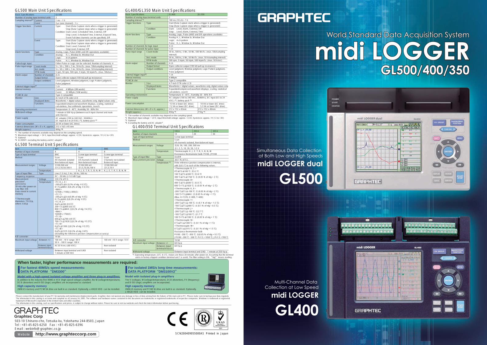
The GL500 provides the ability to precisely measure abnormal events that occur during low-speed sampling (max. 1ms) in high-speed sampling mode (max. 2μs). It incorporates 4MB of memory for data from low-speed sampling, and 32MB of built-in memory for data from high-speed sampling. In addition, it has a PCMCIA-card slot, enabling storage of large data in various PCMCIA media.
■ Capture time: low-speed sampling (approx. values)
1ms 100ms 10s4MB memory 3 minutes 5 hours 23 days64MB PCMCIA card 53 minutes 3 days 370 days
■ Capture time: high-speed sampling (approx. values)2㎲ 5㎲ 10㎲ 20㎲ 1ms
1 channel used. 6.4 sec 16 sec 32 sec 1 min 53 min.2 channels used. 13 sec 26 sec 53 sec 44 min.4 channels used. 20 sec 40 sec 33 min8 channels used. 26 sec 22 min
When an event occurs during measurement, its area is displayed along the time axis of current data as a bar chart. Each of the captured event data is represented in its corresponding memory block of a different color.
After measurement, event data can be viewed along with current data. Current data is displayed in the upper, and event data in the lower section.
The GL500 is compact, with an A5 footprint, providing excellent portability. Three types of amplifiers, for an isolated voltage, a voltage/temperature, and a non-isolated voltage/temperature, are supported, and one of, or a combination of these can be selected to meet measurement applications. Input terminal units can be easily installed and removed by one-touch operation, and can be combined to increase the number of channels up to 16. The GL500 can handle both logic and pulse signals. An alarm output terminal is also provided.
Worry-free battery charging during operation
Leveraging cursor keys for the highest level of ease of use
Supports pulse input (4ch) as standard
A channel for pulse input is available (mode switching with logic is required). This channel supports Count, Inst. and RPM modes (required an optional B-513 cable as input cable).
Cursor keys are adopted for a user-friendly interface, allowing users to operate only with fingertips as when using a mobile phone. Even first-time users can easily perform setups and display measurement data using the step-by-step setting menu. Event data that occurred during measurement can be viewed after measurement. Both waveform and digital data can be visible during measurement at the same time.
Battery charging is available even during measurement.* As with a notebook computer, battery power operation is supported, enabling measurement sessions outdoors.
Digital screenMeasurement values can be viewed in digital format.
Installation and removal by one-touch operation
A maximum of 16 channels
A5size
Bar chart showing event data
Isolated voltage input amplifier
Isolated voltage/temperature input amplifier
Non-isolated voltage/temperature input amplifier
Supports a combination of amplifiers
Stored in PCMCIA media.Data from high-speed
sampling
Data from low-speed sampling
Stored in 4MB memory or PCMCIA media.
Standalone models
GL500VF4-channel isolated voltage measurement
GL500MF4-channel isolated voltage/temperature measurement
GL500MS8-channel voltage/temperature measurement
Digital + Analog screenBoth analog waveforms and digital values are visible.
* Only possible when using the AC adapter or in 24VAC operation. Battery charging may not be available depending on the operating conditions of the main unit.
Complete
ease of use
※ Event data: data captured using high-speed sampling mode when an abnormal event occurs
Current data: data captured using normal, low-speed sampling mode
Memory blocks indicating each event data (blocks displayed in different colors for easy identification)
Excellent operability similar to that of a mobile terminal device Easy, user-friendly operation at fingertips
4-channel isolated voltage/temperature terminal unit 4MF
4-channel isolated voltage terminal unit 4VF
8-channel voltage/temperature terminal unit 8MS
4VF 4MF 8MS
3 4
● Search function● Auto backup function
● Unit conversion/calculation function● Alarm output
10-channel terminal unit 10SU
50-channel terminal unit 50SU
20-channel terminal unit 20SU
Alarm output
Voltage input
Resistance thermometer bulb
External trigger input
Thermocouple input
Logic input
Pulse input
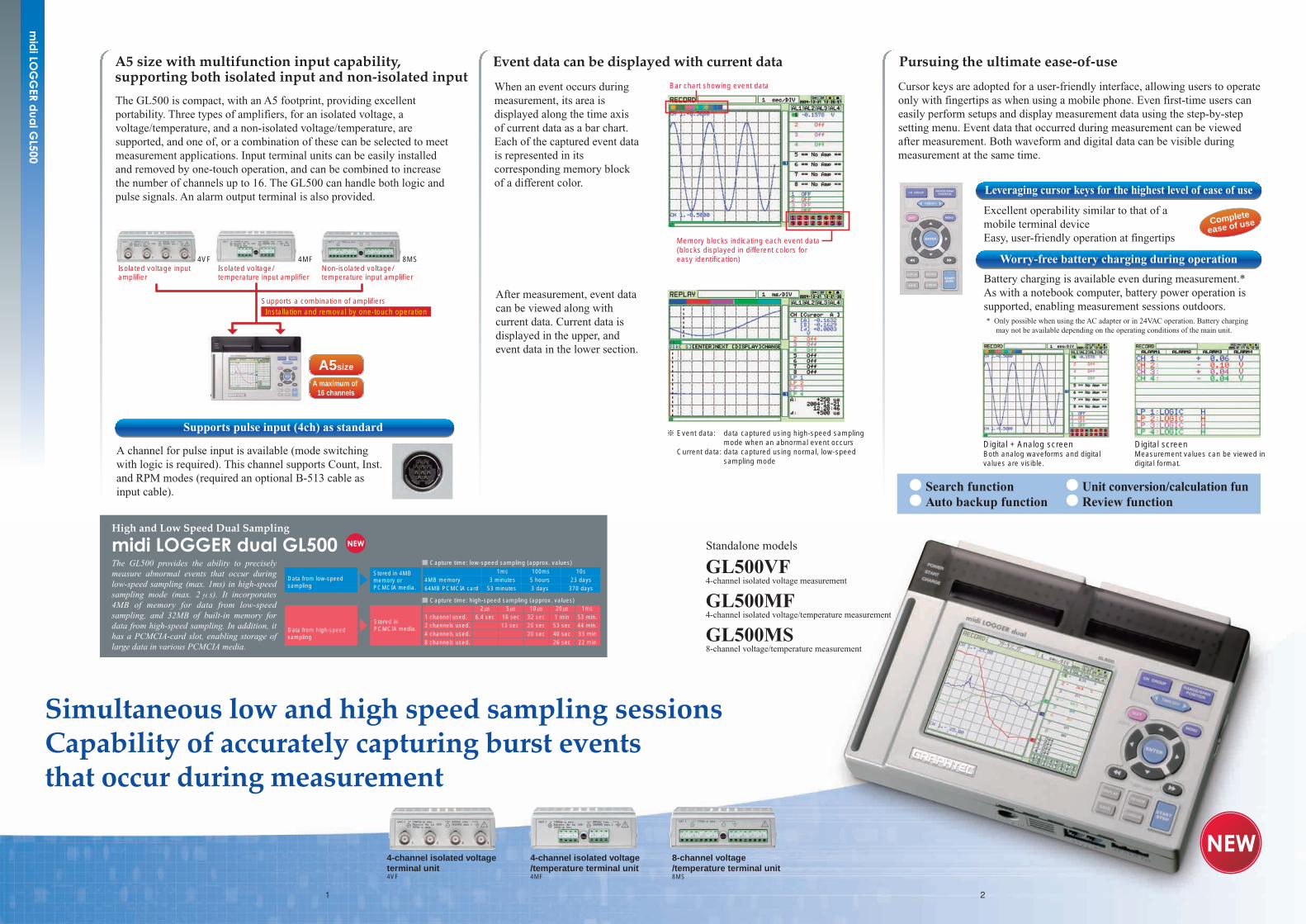
The GL400/350 can capture data in low-speed sampling mode using up to 100 channels. It has built-in 4MB memory for internal data storage. The GL400/350 has a PCMCIA card slot that accepts various media, capable of storing large amounts of data.
The GL400/350 is compact, with an A5 footprint, providing excellent portability. All channels supports isolated inputs, saving you time to connect input cables. It has the ability to perform simultaneous measurement of voltage and temperature. It also supports various inputs, such as pulse (cumulative power, rpm and cumulative flow) and logic, in addition to voltage and temperature.
Cursor keys are adopted, allowing you to operate only with fingertips as when using a mobile phone. Since menus are designed to tailor to the setting steps, even first-time users can easily perform setups and display measurement data. Data observations and report creation are also easy. The screens on the main unit are similar in design to those on the PC monitor, providing almost the same operation procedures on both devices. Depending on the measurement needs, an appropriate screen can be selected from between the four types: Analog + Digital, Analog, Digital + Calculation, and Digital.
A maximum of 100 channels
A5size
Complete
ease of use
Memory capacity Number of channels 100ms 200ms 500ms 1s 10s4MB built-in memory 10 4 hours 8.9 hours 22.4 hours 1.8 days 18 days
20 - 5 hours 12.6 hours 1 day 10 days50 - - 5.2 hours 10.5 hours 4 days
64MB PCMCIA card 10 3 days 6 days 16 days 32 days 337 days20 - 3 days 8 days 17 days 176 days50 - - 3 days 7 days 72 days
The table above indicates the data when analog channels are used. The maximum sampling rates are: 500ms for 30 and 40 channels and 1s for 60 and 70 channels.
Alarm output and logic input
50ch 50ch
Pulse input and external trigger input
Three types of input terminal units are available, each supporting 10, 20, and 50 channels. By combining appropriate terminal units, up to 100 channels are available. This means that the cost per channel significantly decreases, allowing you to purchase multiple terminal units to meet the needs. Low-cost terminal units can be left attached to the objects for measurement, eliminating time and effort to make cable connections at the next measurement.
A maximum of 100 channels are available without decreasing the sampling speed by a synchronized connection between the main units. (An optional cable is required for connecting the main unit and terminal units. Channel expansion is only supported when PC is used to control the main unit.)
Channel expansion by a synchronized connection
Leveraging cursor keys for the highest level of ease of use
Data backup feature (during battery operation)
Excellent operability similar to a mobile terminal device Easy, user-friendly operation at fingertips
An optional battery allows you to use the device in an environment where a stable power source does not exist. During battery operation, the system automatically switches to battery power when AC power fails. When the battery capacity declines to a certain level, the system automatically stores the captured data in the PCMCIA card.
Digital screenData on a certain channel can be closely examined.
Digital + Analog screenBoth analog waveforms and digital values are visible.
Standalone measurement model
GL400 (10-channel terminal unit included)
Measurement with PC model
GL350 (10-channel terminal unit included)
5 6
GL500 Application Software
Connection settingsAllows you to configure USB/TCP-IP connections
Measurement modesAvailable measurement modes are: Y-T, Digital, X-Y, and FFT.
Digital view mode
Main screen
This area displays current data.
This area displays data between cursors.
This area displays the history of events that have occurred and have been captured during measurement. After completion of measurement, click the event data to view the information on that event in a separate window.
Screens for settingsSeparate sheets are available for each of the settings.
Amplifier setting screen
Current setting screen
Event setting screen
Review screenThis screen allows for loading captured data. After data has been loaded, it can be saved to a CSV file, or printed.
Measurement using both the GL500 and GL400/350
Configuring and controlling the GL400/350 for measurement
Only one GL500 and one GL400/350 can be used for simultaneous measurement.
Only one GL400/350 can be configured,controlled, and used for measurement at a time.
GL400 Application Software (OPS022)
Display settingsDisplay type can be easily selected as needed.
Easy configurationThe menu can be defined depending on the measurement steps. Even first-time users will have no problems using the device.
X-Y view mode
Measurement data from the GL500 is displayed here.
Measurement data from the GL400/350 is displayed here.
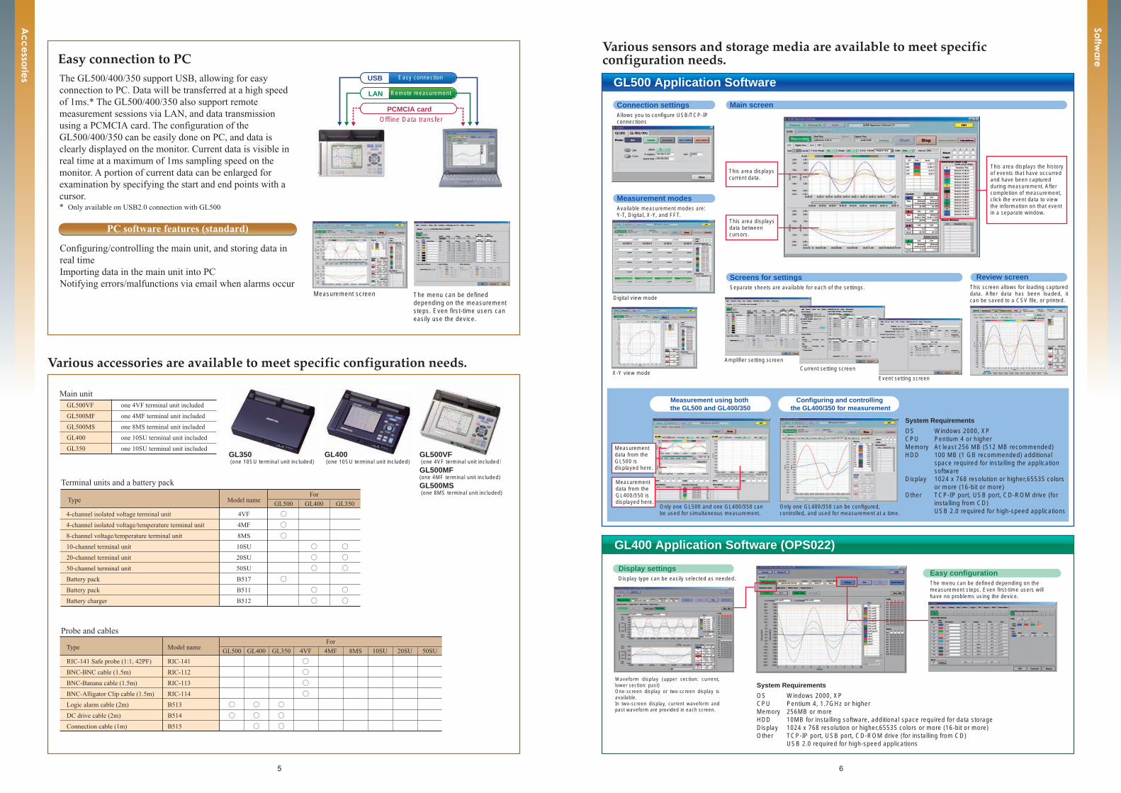
PC software features (standard)
The GL500/400/350 support USB, allowing for easy connection to PC. Data will be transferred at a high speed of 1ms.* The GL500/400/350 also support remote measurement sessions via LAN, and data transmission using a PCMCIA card. The configuration of the GL500/400/350 can be easily done on PC, and data is clearly displayed on the monitor. Current data is visible in real time at a maximum of 1ms sampling speed on the monitor. A portion of current data can be enlarged for examination by specifying the start and end points with a cursor. * Only available on USB2.0 connection with GL500
Configuring/controlling the main unit, and storing data in real timeImporting data in the main unit into PCNotifying errors/malfunctions via email when alarms occur
Measurement screen The menu can be defined depending on the measurement steps. Even first-time users can easily use the device.
Offline Data transfer
USB Easy connection
LAN Remote measurement
PCMCIA card
Type Model nameFor
GL500 GL400 GL350 4VF 4MF 8MS 10SU 20SU 50SU
RIC-141 Safe probe (1:1, 42PF) RIC-141 ○
BNC-BNC cable (1.5m) RIC-112 ○ �
BNC-Banana cable (1.5m) RIC-113 ○ �
BNC-Alligator Clip cable (1.5m) RIC-114 ○ �
Logic alarm cable (2m) B513 ○ ○ ○
DC drive cable (2m) B514 ○ ○ ○�
Connection cable (1m) B515 ○ ○
GL500VF one 4VF terminal unit included
GL500MF one 4MF terminal unit included
GL500MS one 8MS terminal unit included
GL400 one 10SU terminal unit included
GL350 one 10SU terminal unit included
Type Model nameFor
GL500 GL400 GL350
4-channel isolated voltage terminal unit 4VF ○
4-channel isolated voltage/temperature terminal unit 4MF ○
8-channel voltage/temperature terminal unit 8MS ○
10-channel terminal unit 10SU ○ ○
20-channel terminal unit 20SU ○ ○�
50-channel terminal unit 50SU ○ ○�
Battery pack B517 ○
Battery pack B511 ○ ○�
Battery charger B512 ○ ○�
Terminal units and a battery pack
Probe and cables
Main unit
GL500VF (one 4VF terminal unit included)�
GL500MF (one 4MF terminal unit included)
GL500MS (one 8MS terminal unit included)
GL350 (one 10SU terminal unit included)
GL400 (one 10SU terminal unit included)
System Requirements
OS Windows 2000, XPCPU Pentium 4, 1.7GHz or higherMemory 256MB or moreHDD 10MB for installing software, additional space required for data storageDisplay 1024 x 768 resolution or higher,65535 colors or more (16-bit or more)Other TCP-IP port, USB port, CD-ROM drive (for installing from CD)
USB 2.0 required for high-speed applications
System Requirements
OS Windows 2000, XPCPU Pentium 4 or higherMemory At least 256 MB (512 MB recommended)HDD 100 MB (1 GB recommended) additional
space required for installing the application software
Display 1024 x 768 resolution or higher,65535 colors or more (16-bit or more)
Other TCP-IP port, USB port, CD-ROM drive (for installing from CD)USB 2.0 required for high-speed applications
Waveform display (upper section: current, lower section: past) One-screen display or two-screen display is available. In two-screen display, current waveform and past waveform are provided in each screen.


![Sengiergi Serafeim Tikozoglou [Main]](https://static.fdocument.org/doc/165x107/5477673a5806b5e7738b456f/sengiergi-serafeim-tikozoglou-main.jpg)