UNIT V - Vidyarthiplus
17
UNIT V AC voltage controller and cycloconverter www.Vidyarthiplus.com www.Vidyarthiplus.com
Transcript of UNIT V - Vidyarthiplus

UNIT V
AC voltage controller and
cycloconverter
www.Vidyarthiplus.com
www.Vidyarthiplus.com
www.Vidyarthiplus.com
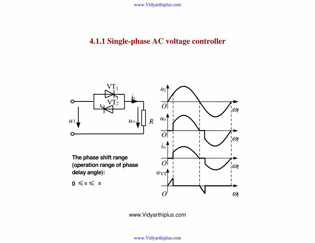
4.1.1 Single-phase AC voltage controller
R u 1 u o
i o
VT 1
VT 2
u
O
u 1
u o
i o
VT
ω t
O ω t
O ω t
O ω t
The phase shift range
(operation range of phase
delay angle): 0 ≤≤≤≤αααα≤≤≤≤ ππππ
www.Vidyarthiplus.com
www.Vidyarthiplus.com

www.Vidyarthiplus.com
• Resistive load, quantitative analysis
RMS value of output voltage
RMS value of output current
RMS value of thyristor current
Power factor of the circuit
( ) ( )π
απα
πωω
π
π
α
−+== ∫ 2sin
2
1dsin2
11
2
1o UttUU (4-1)
(4-2) R
UI o
o =
(4-3) ( ) )2
2sin1(
2
1sin2
2
1 1
2
1
π
α
π
αω
ω
π
π
α+−=
= ∫ R
Utd
R
tUIT
(4-4) π
απα
πλ
−+==== 2sin
2
1
1
o
o1
oo
U
U
IU
IU
S
P
www.Vidyarthiplus.com
www.Vidyarthiplus.com

www.Vidyarthiplus.com
Inductive (Inductor- resistor) load , operation principle
R
L
u 1 u o
i o
VT 1
VT 2
O
u 1
u o
i o
u VT
O
O
ω t O
u G1
u G2
O
O
ω t
ω t
ω t
ω t
ω t
The phase shift range:
φ ≤≤≤≤α ≤≤≤≤ ππππ
www.Vidyarthiplus.com
www.Vidyarthiplus.com
www.Vidyarthiplus.com
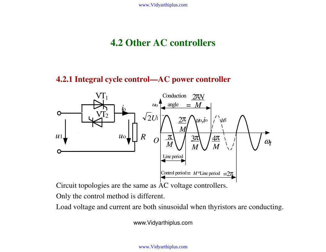
4.2 Other AC controllers
4.2.1 Integral cycle control—AC power controller
Circuit topologies are the same as AC voltage controllers.
Only the control method is different.
Load voltage and current are both sinusoidal when thyristors are conducting.
R u 1 u o
i o
VT 1
VT 2
π
M
Line period
Control period
= M *Line period
= 2 π
4 π
M O
Conduction
angle =
2 π N
M
3 π
M
2 π
M
u o
u 1 u o , i o
ω t
U 1 2
www.Vidyarthiplus.com
www.Vidyarthiplus.com

www.Vidyarthiplus.com
4.3 Thyristor cycloconverters
4.3.1 Single- phase thyristor-cycloconverter
• Circuit configuration and operation principle
P N
Z
ωt ο
uo ap= 2
π Output
voltage
ap=0
Average
output voltage
ap=
2
π
www.Vidyarthiplus.com
www.Vidyarthiplus.com

www.Vidyarthiplus.com
• Single- phase thyristor-cycloconverter
Modes of operation
t
t
t
t
t
O
O
O
O
O
u o , i o
u o i o
t 1 t
2 t 3
t 4 t 5
u o u P
u N
u o
i P
i N
u P u N u o
i o i N i P
blocking P
N
Rectifi
cation
Inver
sion
blocking Rectifi
cation
Inver
sion
www.Vidyarthiplus.com
www.Vidyarthiplus.com
www.Vidyarthiplus.com
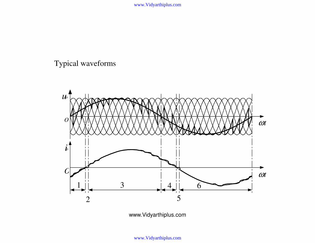
Typical waveforms
1
O
O
2
3 4
5
6
u o
i o
ω t
ω t
www.Vidyarthiplus.com
www.Vidyarthiplus.com

www.Vidyarthiplus.com
• Modulation methods for firing delay angle
Calculation method
– For the rectifier circuit
ωt
ωt
αcosd0o Uu =
tUu oomo sinω=
ttU
Uoo
d0
om sinsincos ωγωα ==
)sin(cos o
1tωγα −=
(4-15)
–For the cycloconverter
output
(4-16)
–Equating (4- 15) and (4-16)
–therefore (4-17)
(4-18)
Principle of cosine
wave-crossing method
u2 u3 u4 u5 u6 u1
ap3 ap4
uo
us2 us3 us4 us5 us6 us1
www.Vidyarthiplus.com
www.Vidyarthiplus.com

www.Vidyarthiplus.com
Output voltage ratio
(Modulation factor)
)10(0
≤≤= γγd
om
U
U
π
2 2 π π ωο t 3 π
2
0
30
60
90
120
150
Output voltage phase angle
α / ( º) γ=0
γ=0.1 0.2
0.3
0.8 0.9 1.0
0.1 0.2 0.3
0.8
0.9
1.0
www.Vidyarthiplus.com
www.Vidyarthiplus.com

www.Vidyarthiplus.com
4.3.2 Three- phase thyristor-cyclo converter
• The configuration with common input line
www.Vidyarthiplus.com
www.Vidyarthiplus.com
www.Vidyarthiplus.com
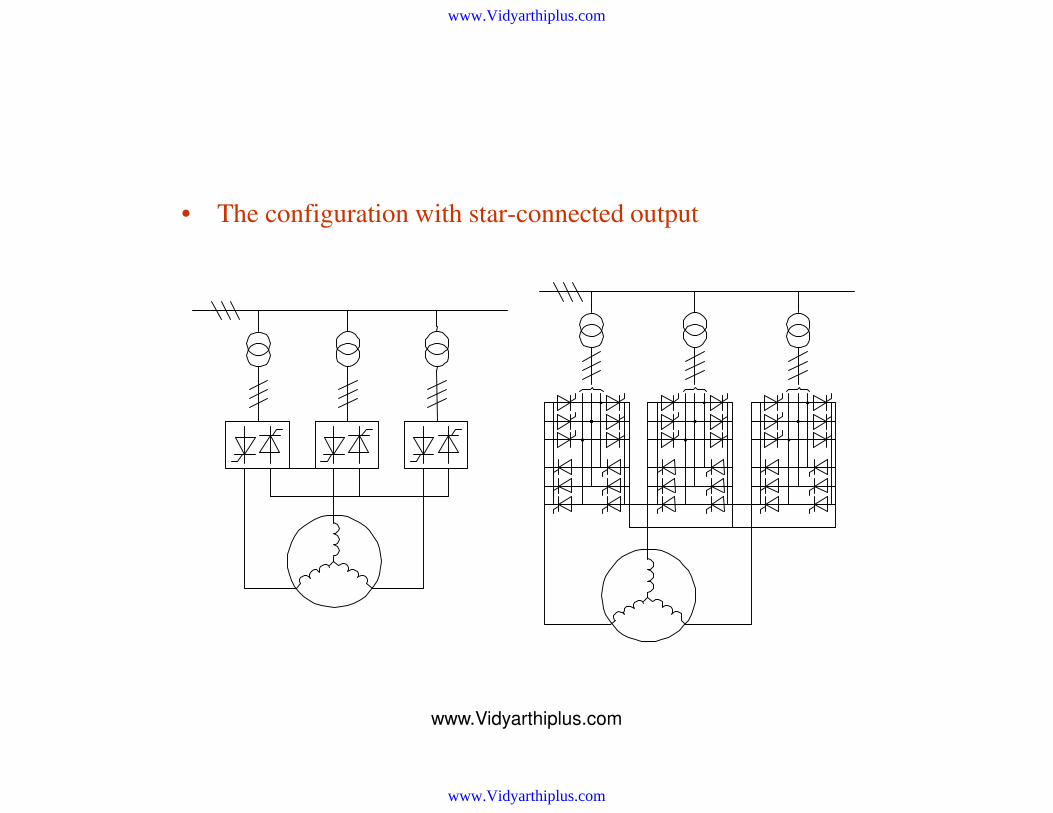
• The configuration with star-connected output
www.Vidyarthiplus.com
www.Vidyarthiplus.com

www.Vidyarthiplus.com
Typical waveforms
200 t / ms
Output voltage
Input current with
Single-phase output
Input current with
3-phase output
200 t / ms
200 t / ms
www.Vidyarthiplus.com
www.Vidyarthiplus.com
www.Vidyarthiplus.com
• Input and output characteristics
The maximum output frequency and the harmonics in the output voltage are the same as in single-phase circuit. Input power factor is a little higher than single-phase circuit. Harmonics in the input current is a little lower thanthe single- phase circuit due to the cancellation of some harmonics among the 3 phases.
To improve the input power factor:
–Use DC bias or 3k order component bias on each of the 3 output phase voltages
• Features and applications
Features:
–Direct frequency conversion—high efficiency
–Bidirectional energy flow, easy to realize 4- quadrant operation
–Very complicated—too many power semiconductor devices
–Low output frequency
–Low input power factor and bad input current waveform
Applications:
–High power low speed AC motor drive
www.Vidyarthiplus.com
www.Vidyarthiplus.com

www.Vidyarthiplus.com
4.4 Matrix converter
• Circuit configuration
input
output
a) b)
a b c
u
v
w
S 1
1
S 1
2
S 1
3
S 2
1
S 2
2
S 2
3
S 3
1
S 3
2
S 3
3
S ij
www.Vidyarthiplus.com
www.Vidyarthiplus.com

www.Vidyarthiplus.com
• Usable input voltage
a) b) c)
a) Single-phase input
voltage
b) Use 3 phase voltages
to construct output
voltage
c) Use 3 line-line voltages
to construct output
voltage
Um
U1m
Um 1
2
√3
2 U1m
www.Vidyarthiplus.com
www.Vidyarthiplus.com
www.Vidyarthiplus.com
• Features
Direct frequency conversion—high efficiency can realize good input and output waveforms, low harmonics, and nearly unity displacement factor
Bidirectional energy flow, easy to realize 4- quadrant operation
Output frequency is not limited by input frequency
No need for bulk capacitor (as compared to indirect frequency converter)
Very complicated—too many power semiconductor devices
Output voltage magnitude is a little lower as compared to indirect frequency converter.
www.Vidyarthiplus.com
www.Vidyarthiplus.com