EZ VFD CONTROL SERIES€¦ · EZ VFD CONTROL SERIES 5000 W. 106th Street Zionsville, Indiana 46077...
12
EZ VFD CONTROL SERIES 5000 W. 106th Street Zionsville, Indiana 46077 Phone (317) 873-5211 Fax (317) 873-1105 www.dartcontrols.com Instruction Manual EZ VFD TM Universal AC Input 110 – 240VAC 230VAC / 3Φ Output 800W LT195 (1019) CONTROLS A-5-4179A TM
Transcript of EZ VFD CONTROL SERIES€¦ · EZ VFD CONTROL SERIES 5000 W. 106th Street Zionsville, Indiana 46077...
EZ V
FD C
ONTR
OL SE
RIES
5000 W. 106th StreetZionsville, Indiana 46077
Phone (317) 873-5211Fax (317) 873-1105
www.dartcontrols.com
Instruction ManualEZ VFDTM
Universal AC Input 110 – 240VAC230VAC / 3Φ Output 800W
LT195 (1019)
CONTROLS
A-5-4179A
TM
1
Table of Contents
Introduction ....................................................................................................................................... 2General Features .............................................................................................................................. 2Models & Options ............................................................................................................................. 3Specifications ................................................................................................................................... 3
EZ VFDTM Electrical ...................................................................................................................... 3EZ VFDTM Mechanical ................................................................................................................... 3Environmental ............................................................................................................................... 3
Mechanical Installation .................................................................................................................... 4Mounting Dimensions ................................................................................................................... 4
Installation & Diagrams .................................................................................................................... 5 Hook-Up Diagram ......................................................................................................................... 5
P9 Terminal Block Hook-Up Diagram ........................................................................................... 5 P9 Terminal Block Descriptions .................................................................................................... 6
Initial Set Up Connections ............................................................................................................... 6 U.S. AC Power Connections ....................................................................................................... 6
Panel/Cover ................................................................................................................................. 6 Pot Board ..................................................................................................................................... 7
'MAX' Speed Pot Set Up ............................................................................................................. 7'MIN' Speed Pot Set Up .............................................................................................................. 8
'Boost' Pot Set Up ....................................................................................................................... 8'Decel' Pot Set Up ....................................................................................................................... 9
'BRK' Pot Set Up ......................................................................................................................... 9EEPROM Store Via JP2 Jumper ................................................................................................. 9
Basic Operating Information ........................................................................................................... 9 Relay Activation ........................................................................................................................... 9
How to Adjust Trimpots ..................................................................................................................... 9Troubleshooting .............................................................................................................................. 10Technical Support Options ............................................................................................................... 10What's Special About www.dartcontrols.com? ................................................................................. 10

2
IntroductionThe EZ VFDTM Series is a volts/Hz variable frequency drive for 3-phase, 230VAC inverter duty AC motors. The EZ VFDTM comes in two styles – open chassis for control panel installation, and a stand-alone NEMA 4X enclosed model. The EZ VFDTM is suited for both constant torque (ex: conveyor, auger) and variable torque (ex: fans, blowers and centrifugal pumps). Care must be taken with variable torque applications not to exceed the load current ratings of the EZ VFDTM.
The EZ VFDTM name indicates the philosophy of the product’s design – it is intended to be the simplest to use Variable Frequency Drive on the market. The factory presets of all adjustments (trimpots) will work well in most applications without change – if changes are needed they are easy to accomplish using the instructions that follow.
Though basic in design, the EZ VFDTM offers an optional ModbusRTU Serial Interface to support networked solutions, and allow remote access / cloud based / advanced smart phone control and data acquisition via Modbus connection to a supervisory control / plc / HMI.
General Features- Digital Signal Processor provides digital accuracy, repeatability, and stability in industrial environments
- Single board design is more rugged and vibration tolerant than stacked / multi-board designs
- Innovative removable Trimpot Board simplifies multiple drive setups, and protects from unwanted adjustment tampering
- Suitable for constant and variable torque applications where the input load does not exceed 800 Watts continuous ( Supply Voltage x Supply Current)
- Universal power supply accepts supply voltages of 110-240VAC @ 50-70Hz
- Transient voltage protection protects device in harsh industrial environments
- Open frame or NEMA 4X enclosed housing
- Euro style terminal strip for control inputs and outputs; 1/4" male spade terminals for supply voltage and motor connections
- Wide operating temperature -10°C to +45°C (14°F to 113°F)
3
Models & Options
SpecificationsEZ VFDTM Electrical
EZ VFDTM Mechanical
EZ VFDTM Environmental
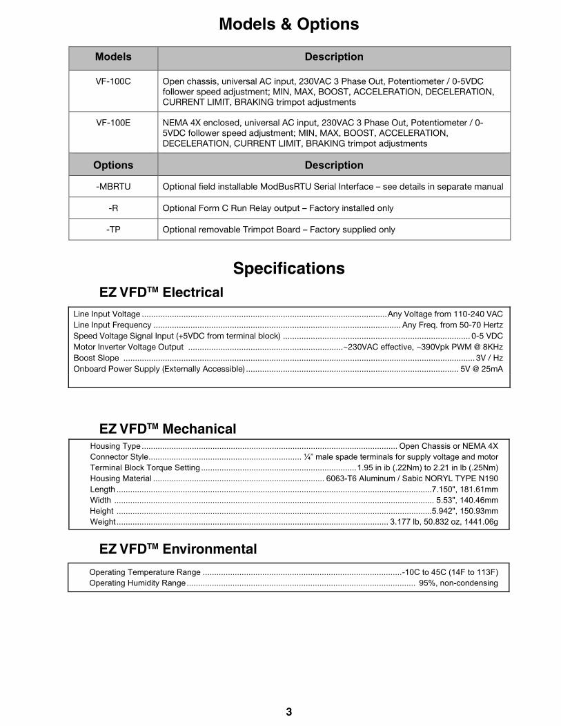
Models Description
VF-100C Open chassis, universal AC input, 230VAC 3 Phase Out, Potentiometer / 0-5VDC follower speed adjustment; MIN, MAX, BOOST, ACCELERATION, DECELERATION, CURRENT LIMIT, BRAKING trimpot adjustments
VF-100E NEMA 4X enclosed, universal AC input, 230VAC 3 Phase Out, Potentiometer / 0-5VDC follower speed adjustment; MIN, MAX, BOOST, ACCELERATION, DECELERATION, CURRENT LIMIT, BRAKING trimpot adjustments
Options Description
-MBRTU Optional field installable ModBusRTU Serial Interface – see details in separate manual
-R Optional Form C Run Relay output – Factory installed only
-TP Optional removable Trimpot Board – Factory supplied only
Line Input Voltage .......................................................................................................... Any Voltage from 110-240 VAC Line Input Frequency ........................................................................................................... Any Freq. from 50-70 Hertz Speed Voltage Signal Input (+5VDC from terminal block) ................................................................................. 0-5 VDC Motor Inverter Voltage Output ...................................................................~230VAC effective, ~390Vpk PWM @ 8KHz Boost Slope ........................................................................................................................................................ 3V / Hz Onboard Power Supply (Externally Accessible) ............................................................................................ 5V @ 25mA
Housing Type ................................................................................................................ Open Chassis or NEMA 4X Connector Style ................................................................... ¼” male spade terminals for supply voltage and motor Terminal Block Torque Setting .................................................................... 1.95 in ib (.22Nm) to 2.21 in lb (.25Nm) Housing Material ........................................................................... 6063-T6 Aluminum / Sabic NORYL TYPE N190 Length ..........................................................................................................................................7.150", 181.61mm Width ............................................................................................................................................ 5.53", 140.46mm Height ..........................................................................................................................................5.942", 150.93mm Weight ....................................................................................................................... 3.177 lb, 50.832 oz, 1441.06g
Operating Temperature Range ....................................................................................... -10C to 45C (14F to 113F) Operating Humidity Range .................................................................................................... 95%, non-condensing

4
Mechanical InstallationMounting Dimensions
Enclosed Dimensions
Figure 1 Chassis Dimensions
Figure 2
7.150
5.530
5.500
.455
5.125 TYP.
ON
OFF0 10
4 6
82
CONTROLS
Variable Frequency Drive
EZ VFD TM
5.3945.942
4.114
6.410

5
Installation & DiagramsHookup Diagram
Figure 3
P9 Terminal Block Hook-Up Diagram
Figure 4
W (RED WIRE)
+5V (WHITE WIRE)
COM (ORANGE WIRE)
C
B
A/TF
+5V
{FUTURE FEATURES
POT OR +5V ISOLATED FOLLOWER INPUT
A
BRK
FWD/REV
RUN
COM
AS REQUIREDBY OPERATOR
CLOSE TO ENABLECLOSE TO REVERSE
JUMPER REQUIRED TO RUN (shipped this way from factory).Remove jumper if remote contacts are used.
orA
A
It is recommended, if the trim pot board is removable (-TP in model number) to unplug it while making connections to the P9 terminal strip.
P9-1
P9-2
P9-3
P9-4
P9-5
P9-6
P9-7
P9-8
P9-9
P9-10
P9-11
AC1
AC2
MOTOR
WU VFAULT
(RED LED)
PWR(GREEN LED)
Note: Insulated female quick connects recommendedfor motor and AC supply connections
Motor Ground
6
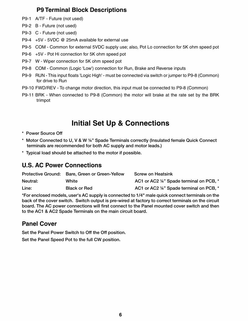
P9 Terminal Block DescriptionsP9-1 A/TF - Future (not used)
P9-2 B - Future (not used)
P9-3 C - Future (not used)
P9-4 +5V - 5VDC @ 25mA available for external use
P9-5 COM - Common for external 5VDC supply use; also, Pot Lo connection for 5K ohm speed pot
P9-6 +5V - Pot Hi connection for 5K ohm speed pot
P9-7 W - Wiper connection for 5K ohm speed pot
P9-8 COM - Common (Logic 'Low') connection for Run, Brake and Reverse inputs
P9-9 RUN - This input floats 'Logic High' - must be connected via switch or jumper to P9-8 (Common) for drive to Run
P9-10 FWD/REV - To change motor direction, this input must be connected to P9-8 (Common)
P9-11 BRK - When connected to P9-8 (Common) the motor will brake at the rate set by the BRK trimpot
Initial Set Up & Connections* Power Source Off
* Motor Connected to U, V & W ¼” Spade Terminals correctly (Insulated female Quick Connect terminals are recommended for both AC supply and motor leads.)
* Typical load should be attached to the motor if possible.
U.S. AC Power ConnectionsProtective Ground: Bare, Green or Green-Yellow Screw on Heatsink
Neutral: White AC1 or AC2 ¼” Spade terminal on PCB, *
Line: Black or Red AC1 or AC2 ¼” Spade terminal on PCB, *
*For enclosed models, user's AC supply is connected to 1/4" male quick connect terminals on the back of the cover switch. Switch output is pre-wired at factory to correct terminals on the circuit board. The AC power connections will first connect to the Panel mounted cover switch and then to the AC1 & AC2 Spade Terminals on the main circuit board.
Panel CoverSet the Panel Power Switch to Off the Off position.
Set the Panel Speed Pot to the full CW position.
7
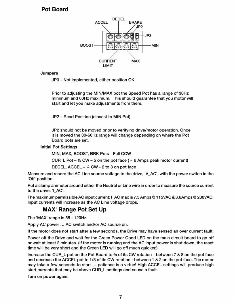
Pot Board
Jumpers
JP3 – Not implemented, either position OK
Prior to adjusting the MIN/MAX pot the Speed Pot has a range of 30Hz minimum and 60Hz maximum. This should guarantee that you motor will start and let you make adjustments from there.
JP2 – Read Position (closest to MIN Pot)
JP2 should not be moved prior to verifying drive/motor operation. Once it is moved the 30-60Hz range will change depending on where the Pot Board pots are set.
Initial Pot Settings
MIN, MAX, BOOST, BRK Pots - Full CCW
CUR_L Pot – ½ CW – 5 on the pot face ( ~ 6 Amps peak motor current)
DECEL, ACCEL – ¼ CW - 2 to 3 on pot face
Measure and record the AC Line source voltage to the drive, ‘V_AC’, with the power switch in the 'Off' position.
Put a clamp ammeter around either the Neutral or Line wire in order to measure the source current to the drive, ‘I_AC’.
The maximum permissible AC input current: I_AC max is 7.3 Amps @ 115VAC & 3.6Amps @ 230VAC. Input currents will increase as the AC Line voltage drops.
'MAX' Range Pot Set UpThe 'MAX' range is 58 - 120Hz.
Apply AC power … AC switch and/or AC source on.
If the motor does not start after a few seconds, the Drive may have sensed an over current fault.
Power off the Drive and wait for the Green Power Good LED on the main circuit board to go off or wait at least 2 minutes. (If the motor is running and the AC input power is shut down, the reset time will be very short and the Green LED will go off much quicker.)
Increase the CUR_L pot on the Pot Board to ¾ of its CW rotation – between 7 & 8 on the pot face and decrease the ACCEL pot to 1/8 of its CW rotation - between 1 & 2 on the pot face. The motor may take a few seconds to start … patience is a virtue! High ACCEL settings will produce high start currents that may be above CUR_L settings and cause a fault.
Turn on power again.
ACCELDECEL
BRAKE
BOOST
CURRENT LIMIT
MAX
MIN
JP2
JP3
8
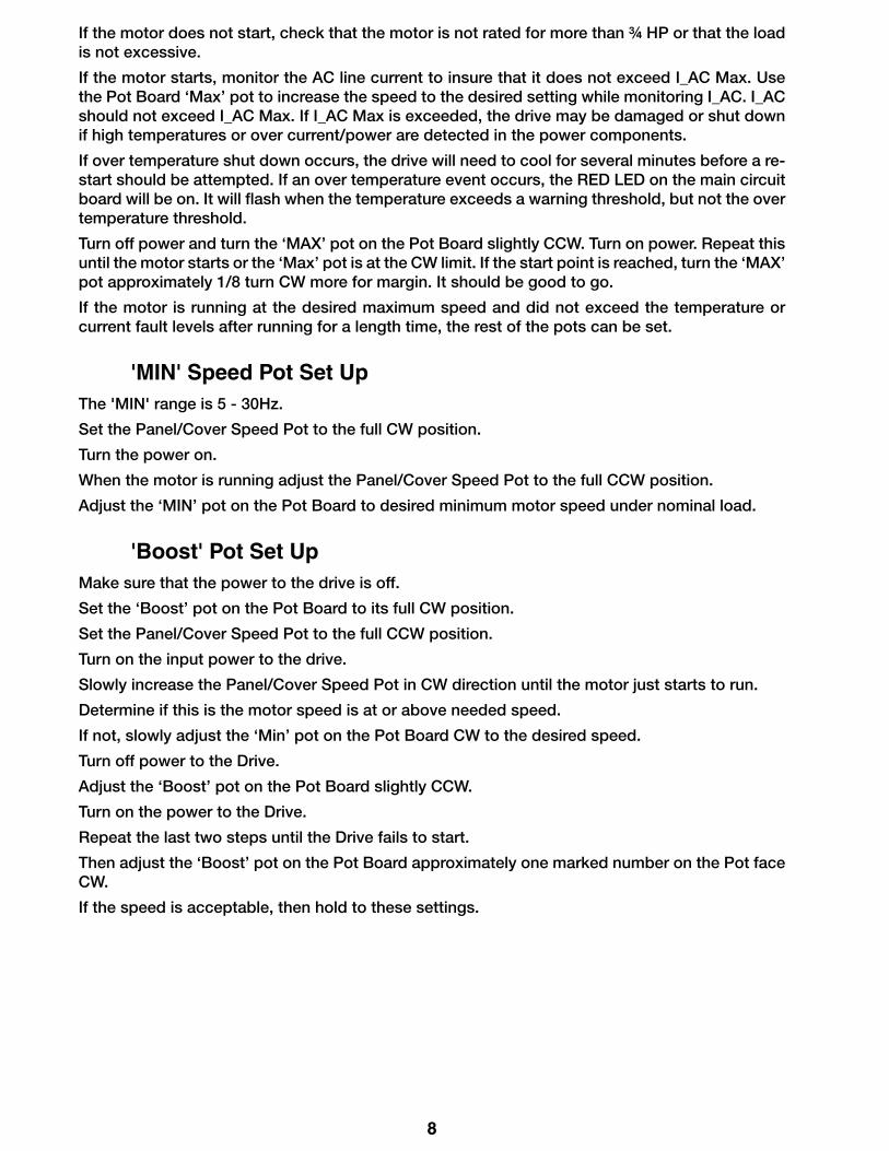
If the motor does not start, check that the motor is not rated for more than ¾ HP or that the load is not excessive.
If the motor starts, monitor the AC line current to insure that it does not exceed I_AC Max. Use the Pot Board ‘Max’ pot to increase the speed to the desired setting while monitoring I_AC. I_AC should not exceed I_AC Max. If I_AC Max is exceeded, the drive may be damaged or shut down if high temperatures or over current/power are detected in the power components.
If over temperature shut down occurs, the drive will need to cool for several minutes before a re-start should be attempted. If an over temperature event occurs, the RED LED on the main circuit board will be on. It will flash when the temperature exceeds a warning threshold, but not the over temperature threshold.
Turn off power and turn the ‘MAX’ pot on the Pot Board slightly CCW. Turn on power. Repeat this until the motor starts or the ‘Max’ pot is at the CW limit. If the start point is reached, turn the ‘MAX’ pot approximately 1/8 turn CW more for margin. It should be good to go.
If the motor is running at the desired maximum speed and did not exceed the temperature or current fault levels after running for a length time, the rest of the pots can be set.
'MIN' Speed Pot Set UpThe 'MIN' range is 5 - 30Hz.
Set the Panel/Cover Speed Pot to the full CW position.
Turn the power on.
When the motor is running adjust the Panel/Cover Speed Pot to the full CCW position.
Adjust the ‘MIN’ pot on the Pot Board to desired minimum motor speed under nominal load.
'Boost' Pot Set UpMake sure that the power to the drive is off.
Set the ‘Boost’ pot on the Pot Board to its full CW position.
Set the Panel/Cover Speed Pot to the full CCW position.
Turn on the input power to the drive.
Slowly increase the Panel/Cover Speed Pot in CW direction until the motor just starts to run.
Determine if this is the motor speed is at or above needed speed.
If not, slowly adjust the ‘Min’ pot on the Pot Board CW to the desired speed.
Turn off power to the Drive.
Adjust the ‘Boost’ pot on the Pot Board slightly CCW.
Turn on the power to the Drive.
Repeat the last two steps until the Drive fails to start.
Then adjust the ‘Boost’ pot on the Pot Board approximately one marked number on the Pot face CW.
If the speed is acceptable, then hold to these settings.

9
Enable Input Current Limit IGBT Temperature exceeded shutdown value
EEPROM Corruption Relay state
Active Not exceeded Not Exceeded Not detected ON
Inactive Not exceeded Not Exceeded Not detected OFF
Active Exceeded Not exceeded Not detected OFF
Active Not exceeded Exceeded Not detected OFF
Active Not exceeded Not exceeded Detected OFF
'Decel' Pot Set UpAdjust the ‘DECEL’ pot on the Pot Board to its ¼ CW position.
Turn on the drive and adjust the Panel/Cover Speed Pot to it full CW position.
Quickly turn the Panel/Cover Speed Pot to its full CCW position. Return the Panel/Cover Speed Pot to it full CW position.
Slightly adjust the ‘DECEL’ for more or less deceleration as desired.
Quickly turn the Panel/Cover Speed Pot to its full CCW position to evaluate the change.
Repeat as needed.
Less deceleration is better for reliability of the Drive as it puts less stress on the electronics as does less acceleration.
'BRK' Pot Set UpConnect a switch between ‘COM’ and ‘BRK’ on Terminal Block P9.
Turn on the power to the Drive.
Close the ‘BRK’ switch that you have connected.
The Drive should slow the motor at a rate determined by the ‘BRK’ Pot setting.
Toggle the ‘BRK’ switch ON & Off as the ‘BRK’ pot on the Pot Board is alternately adjusted in small increments to determine the desired setting. The system will need to be restarted each time.
As with ‘ACCEL’ and ‘DECEL’, less/slower ‘BRK’ is better as it will cause less stress on the electronics.
EEPROM Store Via JP2 JumperOnce all Pots have been set for the desired performance, Jumper JP2 can be move to the ‘Store’ position (away from the ‘MIN’ Pot) so that the desired settings can be saved to the EEPROM memory on the main circuit board. If configured as pluggable, the Pot Board can be removed at this point so that inadvertent or ‘mischi
Basic Operating Information
Run Relay Activation:The Run Relay is deactivated on a logical OR combination of ‘Inactive Enable input’, ‘Over Current fault’, ‘Over Temperature fault’ and ‘EEPROM Corruption fault’. The Run Relay is active when none of the fault conditions exist and the ‘Enable input’ is active.

10
TroubleshootingTechnical Support Options
• Visit the Dart Controls Web Site at: www.dartcontrols.com
• Email technical support at: [email protected]
• Telephone technical support at 317-873-5211
What's Special About www.dartcontrols.com?• Changes to printed material and product offerings first appear online
• Product manuals and other literature are easily accessible
• All information can be easily displayed or printed as needed
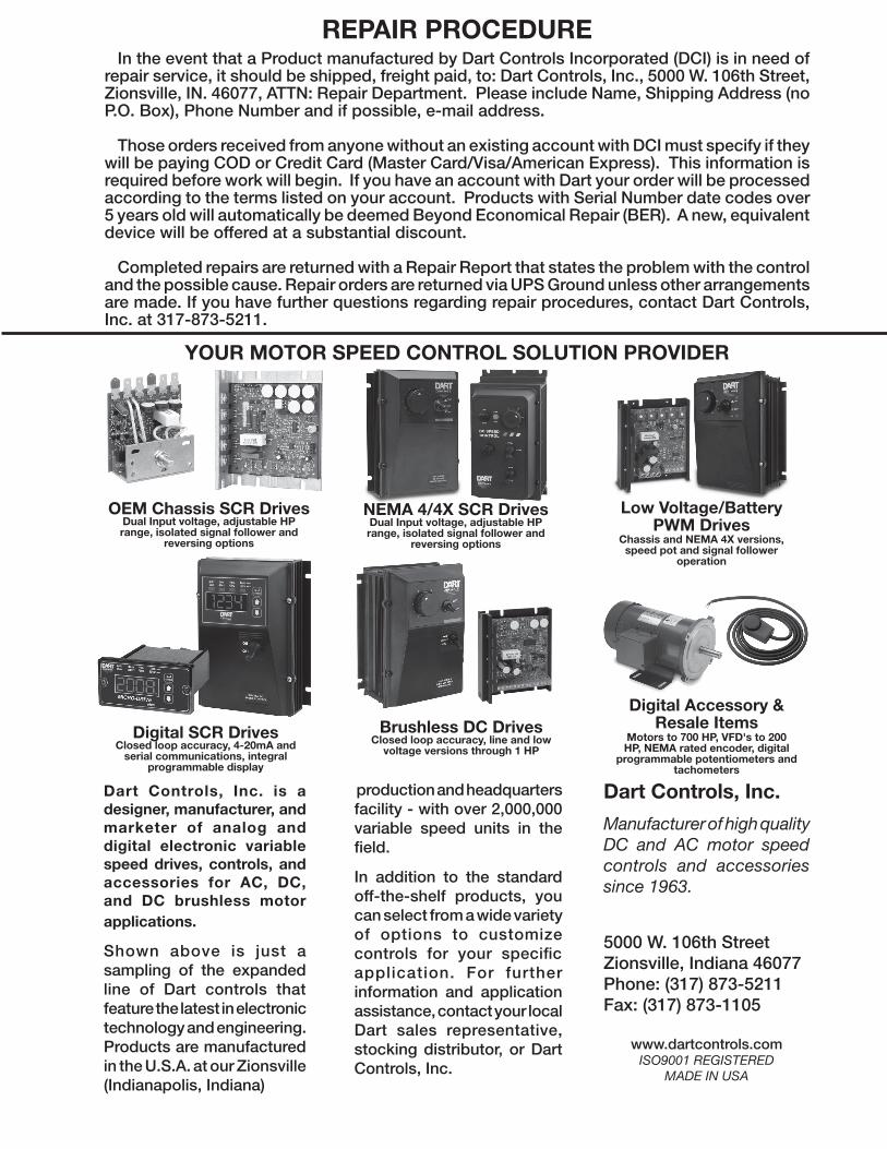
In the event that a Product manufactured by Dart Controls Incorporated (DCI) is in need of repair service, it should be shipped, freight paid, to: Dart Controls, Inc., 5000 W. 106th Street, Zionsville, IN. 46077, ATTN: Repair Department. Please include Name, Shipping Address (no P.O. Box), Phone Number and if possible, e-mail address.
Those orders received from anyone without an existing account with DCI must specify if they will be paying COD or Credit Card (Master Card/Visa/American Express). This information is required before work will begin. If you have an account with Dart your order will be processed according to the terms listed on your account. Products with Serial Number date codes over 5 years old will automatically be deemed Beyond Economical Repair (BER). A new, equivalent device will be offered at a substantial discount.
Completed repairs are returned with a Repair Report that states the problem with the control and the possible cause. Repair orders are returned via UPS Ground unless other arrangements are made. If you have further questions regarding repair procedures, contact Dart Controls, Inc. at 317-873-5211.
REPAIR PROCEDURE
Dart Controls, Inc.
Manufacturer of high quality DC and AC motor speed controls and accessories since 1963.
5000 W. 106th StreetZionsville, Indiana 46077Phone: (317) 873-5211Fax: (317) 873-1105
www.dartcontrols.comISO9001 REGISTERED
MADE IN USA
production and headquarters facility - with over 2,000,000 variable speed units in the field.
In addition to the standard off-the-shelf products, you can select from a wide variety of options to customize controls for your specific application. For further information and application assistance, contact your local Dart sales representative, stocking distributor, or Dart Controls, Inc.
Dart Controls, Inc. is a designer, manufacturer, and marketer of analog and digital electronic variable speed drives, controls, and accessories for AC, DC, and DC brushless motor applications.
Shown above is just a sampling of the expanded line of Dart controls that feature the latest in electronic technology and engineering. Products are manufactured in the U.S.A. at our Zionsville (Indianapolis, Indiana)
YOUR MOTOR SPEED CONTROL SOLUTION PROVIDER
Digital SCR DrivesClosed loop accuracy, 4-20mA and
serial communications, integral programmable display
NEMA 4/4X SCR DrivesDual Input voltage, adjustable HP range, isolated signal follower and
reversing options
Low Voltage/BatteryPWM Drives
Chassis and NEMA 4X versions, speed pot and signal follower
operation
Digital Accessory & Resale Items
Motors to 700 HP, VFD's to 200 HP, NEMA rated encoder, digital
programmable potentiometers and tachometers
Brushless DC DrivesClosed loop accuracy, line and low
voltage versions through 1 HP
OEM Chassis SCR DrivesDual Input voltage, adjustable HP range, isolated signal follower and
reversing options