4530 Lecture PPT - 5 - VFDs · A Variable Frequency Drive (VFD) is a type of motor drive that is...
19
1 ECET 4530 Industrial Motor Control Variable Frequency Drives Electronic motor drives are devices that control the speed, torque and/or rotational direction of electric motors. Electronic motor drives can be divided into two categories: • AC Motor Drives • DC Motor Drives This presentation will focus on AC Motor Drives. Electronic Motor Drives
Transcript of 4530 Lecture PPT - 5 - VFDs · A Variable Frequency Drive (VFD) is a type of motor drive that is...
1
ECET 4530Industrial Motor Control
Variable Frequency Drives
Electronic motor drives are devices that control the speed, torque and/or rotational direction of electric motors.
Electronic motor drives can be divided into two categories:
• AC Motor Drives
• DC Motor Drives
This presentation will focus on AC Motor Drives.
Electronic Motor Drives
2
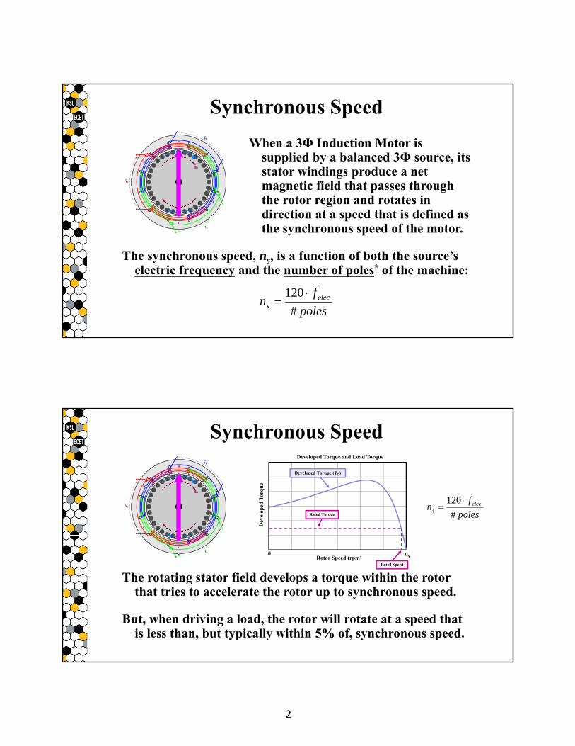
When a 3Φ Induction Motor is supplied by a balanced 3Φ source, its stator windings produce a net magnetic field that passes through the rotor region and rotates in direction at a speed that is defined as the synchronous speed of the motor.
The synchronous speed, ns, is a function of both the source’s electric frequency and the number of poles* of the machine:
poles
fn elec
s #
120
Synchronous Speed
Va~
Vb~
Vc~
a
a'
b
b'
c
c'
s
ns
nr
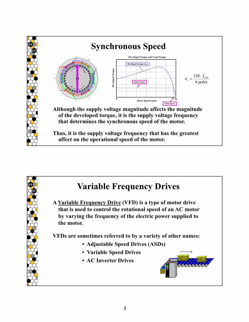
The rotating stator field develops a torque within the rotor that tries to accelerate the rotor up to synchronous speed.
But, when driving a load, the rotor will rotate at a speed that is less than, but typically within 5% of, synchronous speed.
poles
fn elec
s #
120
Synchronous Speed
Va~
Vb~
Vc~
a
a'
b
b'
c
c'
s
ns
nr
Dev
elop
ed T
orq
ue
Rotor Speed (rpm)
Developed Torque and Load Torque
Rated Speed
ns0
Rated Torque
Developed Torque (TD)
3
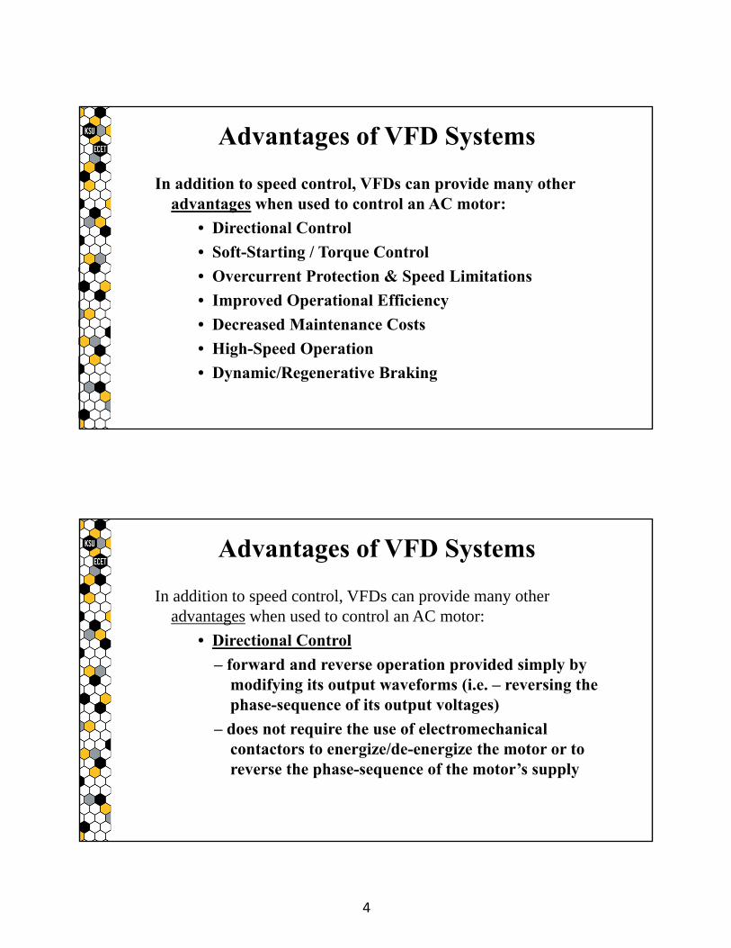
Although the supply voltage magnitude affects the magnitude of the developed torque, it is the supply voltage frequency that determines the synchronous speed of the motor.
Thus, it is the supply voltage frequency that has the greatest affect on the operational speed of the motor.
poles
fn elec
s #
120
Synchronous Speed
Va~
Vb~
Vc~
a
a'
b
b'
c
c'
s
ns
nr
Dev
elop
ed T
orq
ue
Rotor Speed (rpm)
Developed Torque and Load Torque
Rated Speed
ns0
Rated Torque
Developed Torque (TD)
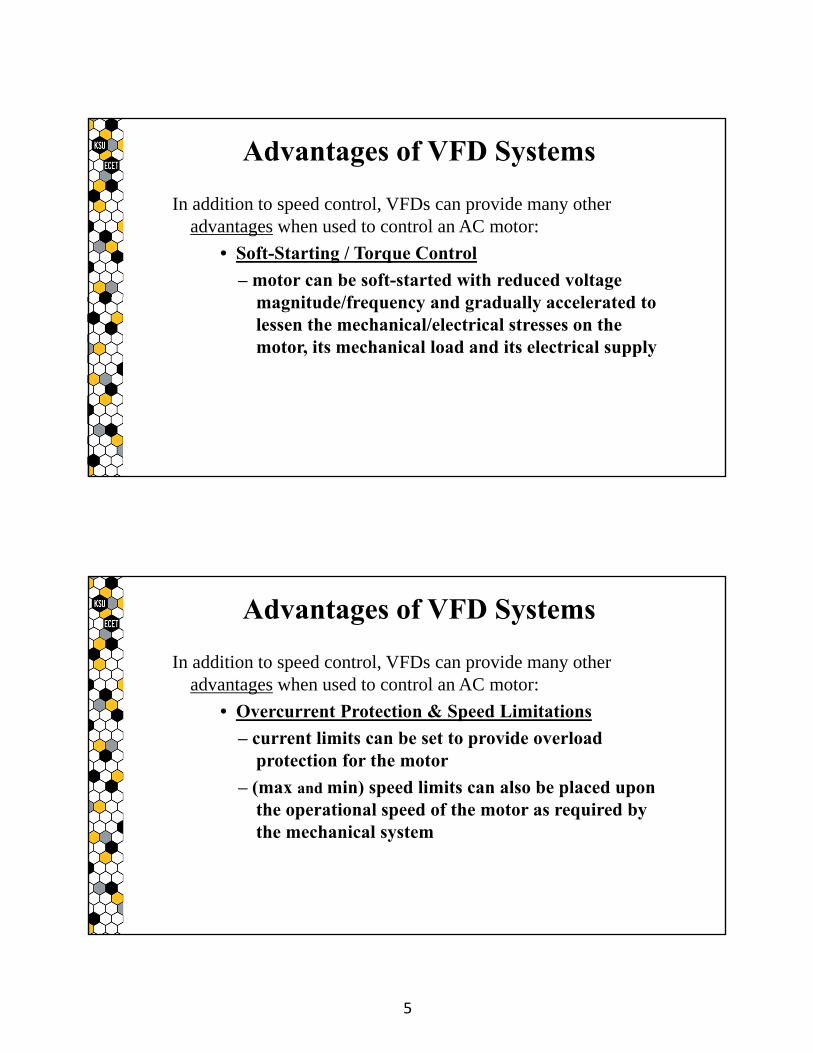
A Variable Frequency Drive (VFD) is a type of motor drive that is used to control the rotational speed of an AC motor by varying the frequency of the electric power supplied to the motor.
VFDs are sometimes referred to by a variety of other names:
• Adjustable Speed Drives (ASDs)
• Variable Speed Drives
• AC Inverter Drives
Variable Frequency Drives
4
In addition to speed control, VFDs can provide many other advantages when used to control an AC motor:
• Directional Control
• Soft-Starting / Torque Control
• Overcurrent Protection & Speed Limitations
• Improved Operational Efficiency
• Decreased Maintenance Costs
• High-Speed Operation
• Dynamic/Regenerative Braking
Advantages of VFD Systems
In addition to speed control, VFDs can provide many other advantages when used to control an AC motor:
• Directional Control
– forward and reverse operation provided simply by modifying its output waveforms (i.e. – reversing the phase-sequence of its output voltages)
– does not require the use of electromechanical contactors to energize/de-energize the motor or to reverse the phase-sequence of the motor’s supply
Advantages of VFD Systems
5
In addition to speed control, VFDs can provide many other advantages when used to control an AC motor:
• Soft-Starting / Torque Control
– motor can be soft-started with reduced voltage magnitude/frequency and gradually accelerated to lessen the mechanical/electrical stresses on the motor, its mechanical load and its electrical supply
Advantages of VFD Systems
In addition to speed control, VFDs can provide many other advantages when used to control an AC motor:
• Overcurrent Protection & Speed Limitations
– current limits can be set to provide overload protection for the motor
– (max and min) speed limits can also be placed upon the operational speed of the motor as required by the mechanical system
Advantages of VFD Systems
6
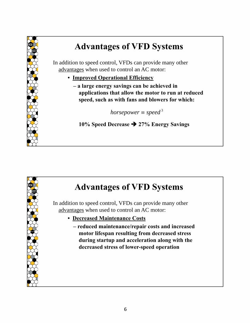
In addition to speed control, VFDs can provide many other advantages when used to control an AC motor:
• Improved Operational Efficiency
– a large energy savings can be achieved in applications that allow the motor to run at reduced speed, such as with fans and blowers for which:
10% Speed Decrease 27% Energy Savings
Advantages of VFD Systems
3speedhorsepower
In addition to speed control, VFDs can provide many other advantages when used to control an AC motor:
• Decreased Maintenance Costs
– reduced maintenance/repair costs and increased motor lifespan resulting from decreased stress during startup and acceleration along with the decreased stress of lower-speed operation
Advantages of VFD Systems
7
In addition to speed control, VFDs can provide many other advantages when used to control an AC motor:
• High-Speed Operation
– greater than rated speed operation possible by increasing frequency above its rated value provided that rated power is not exceeded and that other mechanical and electrical concerns are addressed
Advantages of VFD Systems
In addition to speed control, VFDs can provide many other advantages when used to control an AC motor:
• Dynamic / Regenerative Braking
– an AC motor is transformed into an AC generator when it is rotating faster than its synchronous speed (which is set by the VFD’s output frequency) such that the mechanical system’s rotational energy is converted back into electrical energy, resulting in a magnetic braking force being applied to the shaft of the machine.
Advantages of VFD Systems
8
In addition to speed control, VFDs can provide many other advantages when used to control an AC motor:
• Dynamic Braking
– during dynamic braking, the generated electrical energy is dissipated as heat either in the rotor conductors or in a bank of eternal resistors
Advantages of VFD Systems
In addition to speed control, VFDs can provide many other advantages when used to control an AC motor:
• Regenerative Braking
– during regenerative braking, the generated electrical energy is recovered and returned to the supply
– regenerative braking requires more complicated circuitry than dynamic braking
Advantages of VFD Systems
9
VFDs are typically configurable, allowing the user to set different operational characteristics such as the rate at which the drive will accelerate or decelerate the AC motor.
Additionally, VFDs are often networkable, allowing them to be controlled remotely as an individual unit or as part of a complex motor control system involving multiple VFDs and/or devices.
Note that complex motor control systems are typically controlled by Programmable Logic Controllers (PLCs). PLCs are covered in a
separate presentation.
Advantages of VFD Systems
Although VFDs come from many different manufacturers in a wide variety of sizes and with a large variety of features, most VFDs are constructed using the same operational components to provide their primary function:
the conversion of a constant-frequency AC waveform into a variable frequency (and variable magnitude) AC waveform.
VFD Operation
10
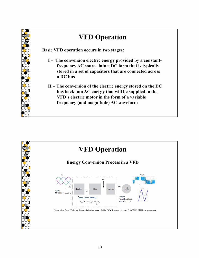
Basic VFD operation occurs in two stages:
I – The conversion electric energy provided by a constant-frequency AC source into a DC form that is typically stored in a set of capacitors that are connected across a DC bus
II – The conversion of the electric energy stored on the DC bus back into AC energy that will be supplied to the VFD’s electric motor in the form of a variable frequency (and magnitude) AC waveform
VFD Operation
Energy Conversion Process in a VFD
Figure taken from “Technical Guide – Induction motors fed by PWM frequency inverters” by WEG ©2009 – www.weg.net
VFD Operation
11
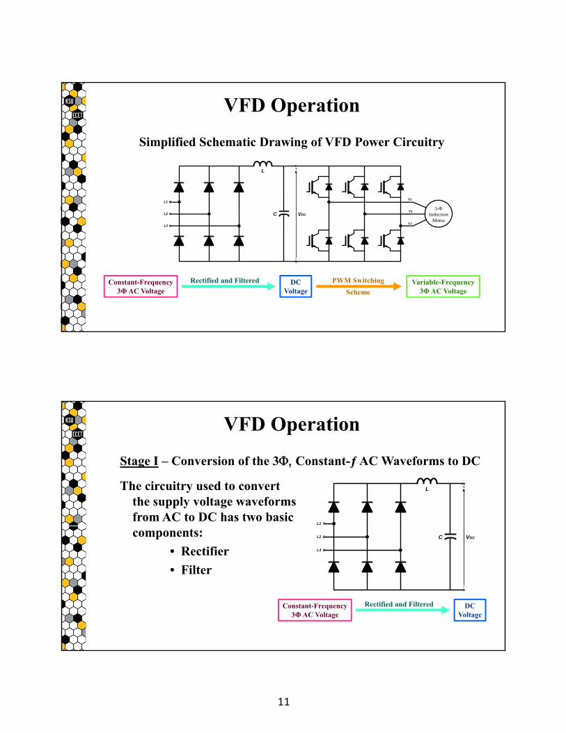
Simplified Schematic Drawing of VFD Power Circuitry
+
-
VDCC
L
L1
L2
L3
3-Induction
Motor
T1
T3
T2
VFD Operation
Constant-Frequency3ΦAC Voltage
Rectified and Filtered DCVoltage
PWM Switching
SchemeVariable-Frequency
3ΦAC Voltage
Stage I – Conversion of the 3 Constant-ƒ AC Waveforms to DC
The circuitry used to convert the supply voltage waveforms from AC to DC has two basic components:
• Rectifier
• Filter
VFD Operation
+
-
VDCC
L
L1
L2
L3
Constant-Frequency3ΦAC Voltage
Rectified and Filtered DCVoltage
12
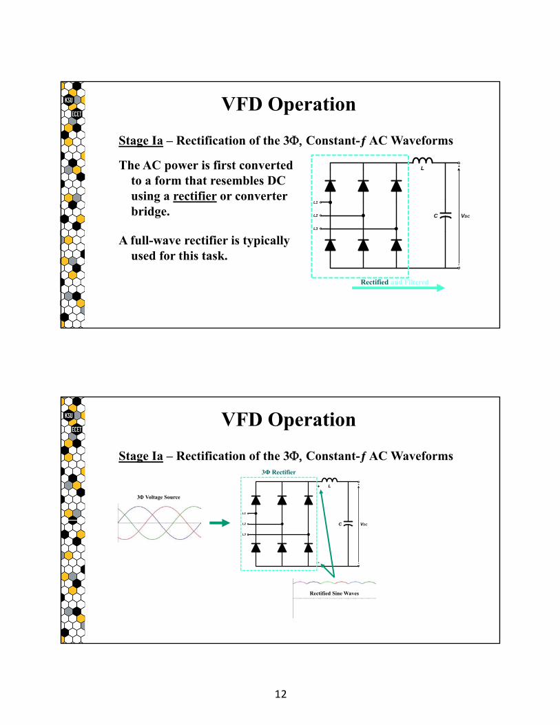
Stage Ia – Rectification of the 3 Constant-ƒ AC Waveforms
The AC power is first converted to a form that resembles DC using a rectifier or converter bridge.
A full-wave rectifier is typically used for this task.
VFD Operation
+
-
VDCC
L
L1
L2
L3
Rectified and Filtered
Stage Ia – Rectification of the 3 Constant-ƒ AC Waveforms
VFD Operation
+
-
VDCC
L
L1
L2
L3
+
-
3 Voltage Source
Rectified Sine Waves
3Φ Rectifier
13
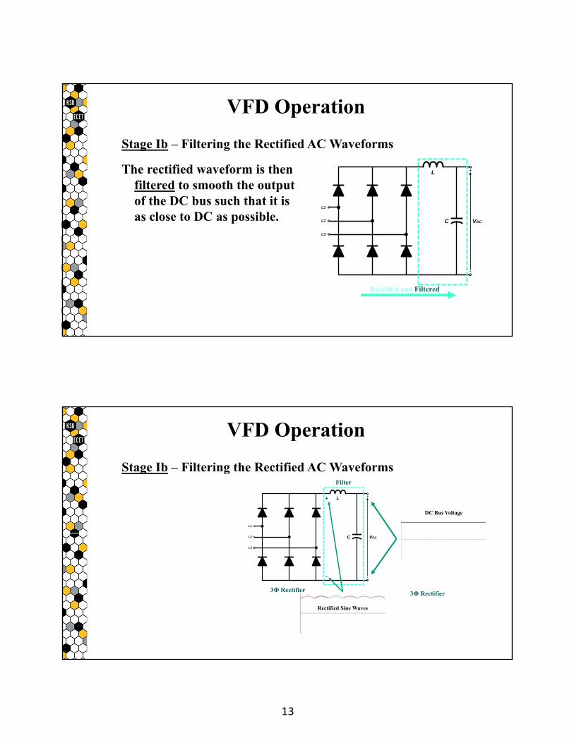
Stage Ib – Filtering the Rectified AC Waveforms
The rectified waveform is then filtered to smooth the output of the DC bus such that it is as close to DC as possible.
+
-
VDCC
L
L1
L2
L3
VFD Operation
Rectified and Filtered
Stage Ib – Filtering the Rectified AC Waveforms
VFD Operation
+
-
VDCC
L
L1
L2
L3
+
-
DC Bus Voltage
Rectified Sine Waves
3Φ Rectifier3Φ Rectifier
Filter
14
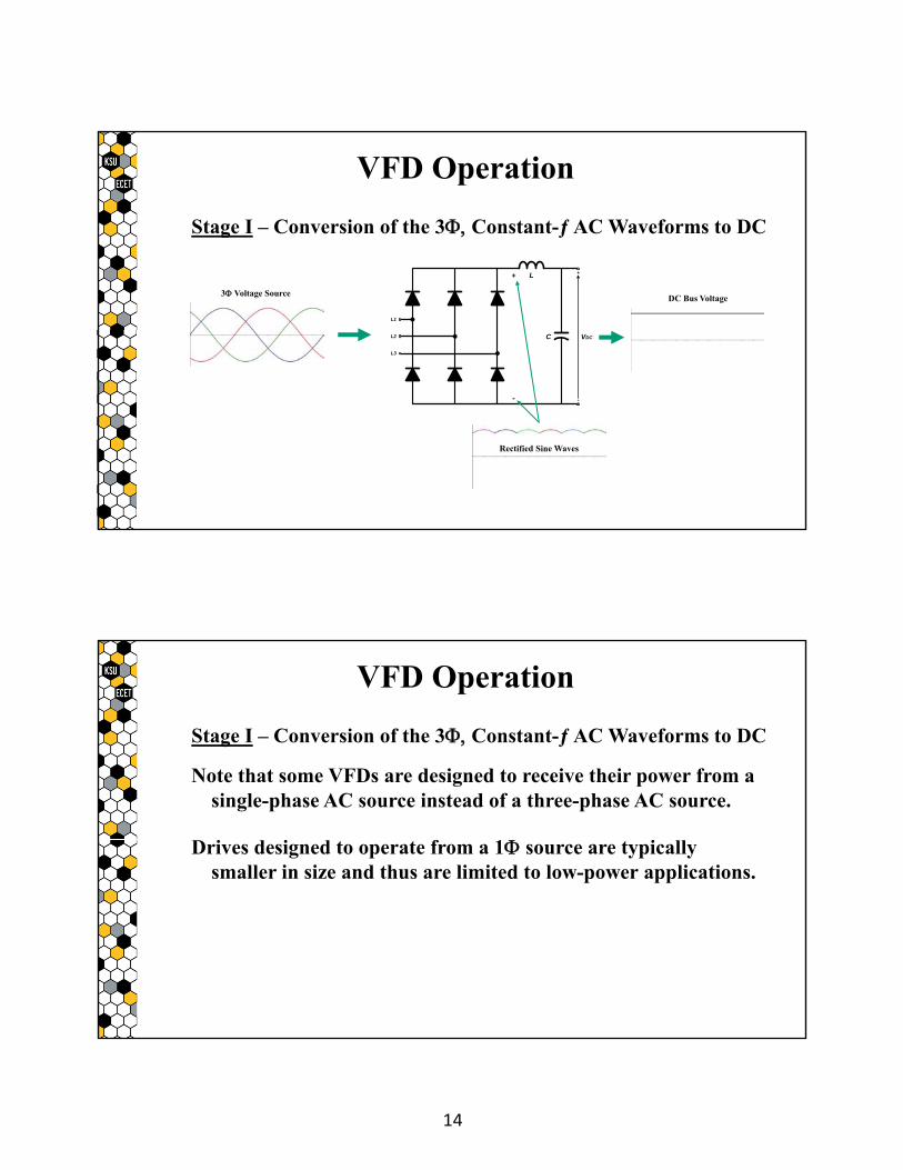
Stage I – Conversion of the 3 Constant-ƒ AC Waveforms to DC
VFD Operation
+
-
VDCC
L
L1
L2
L3
+
-
3 Voltage SourceDC Bus Voltage
Rectified Sine Waves
Stage I – Conversion of the 3 Constant-ƒ AC Waveforms to DC
Note that some VFDs are designed to receive their power from a single-phase AC source instead of a three-phase AC source.
Drives designed to operate from a 1 source are typically smaller in size and thus are limited to low-power applications.
VFD Operation
15
Stage I – Conversion of the 3 Constant-ƒ AC Waveforms to DC
Also note that some VFDs that are designed to receive their power from a 3 source may be configured to instead receive their power from a 1 source provided that the drive is de-rated to prevent drawing too much current into the one operational phase of its three-phase rectifier circuit.
VFD Operation
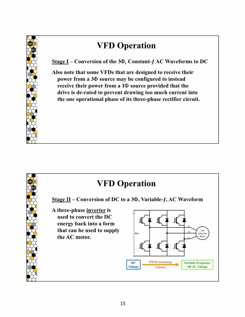
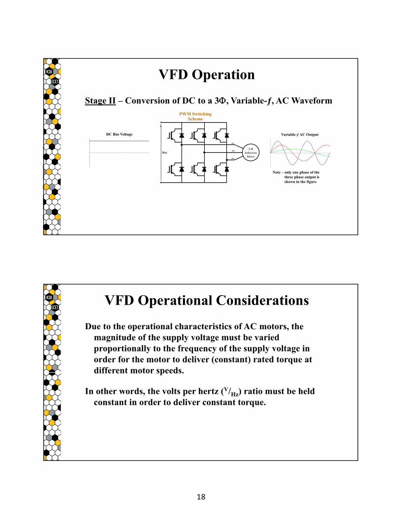
Stage II – Conversion of DC to a 3, Variable-ƒ, AC Waveform
A three-phase inverter is used to convert the DC energy back into a form that can be used to supply the AC motor.
VFD Operation
+
-
VDC
3-Induction
Motor
T1
T3
T2
DCVoltage
PWM Switching
SchemeVariable-Frequency
3ΦAC Voltage
16
Stage II – Conversion of DC to a 3, Variable-ƒ, AC Waveform
The inverter typically utilizes a set of Insulated Gate Bipolar Transistors (IGBTs) that are switched on and off using a Pulse Width Modulation (PWM) switching pattern.
+
-
VDC
3-Induction
Motor
T1
T3
T2
VFD Operation
DCVoltage
PWM Switching
SchemeVariable-Frequency
3ΦAC Voltage
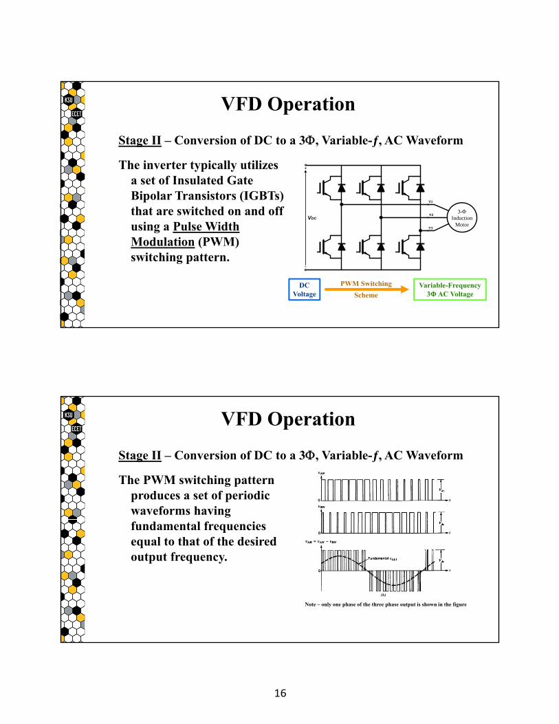
Stage II – Conversion of DC to a 3, Variable-ƒ, AC Waveform
The PWM switching pattern produces a set of periodic waveforms having fundamental frequencies equal to that of the desired output frequency.
VFD Operation
Note – only one phase of the three phase output is shown in the figure
17
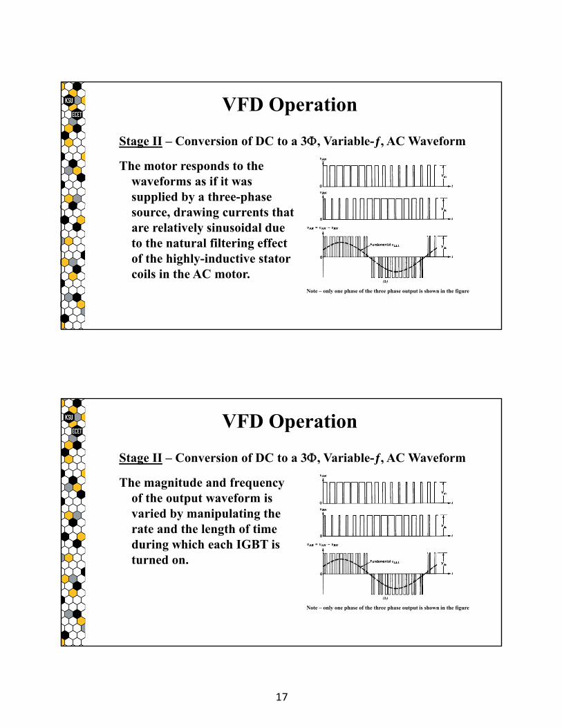
Stage II – Conversion of DC to a 3, Variable-ƒ, AC Waveform
The motor responds to the waveforms as if it was supplied by a three-phase source, drawing currents that are relatively sinusoidal due to the natural filtering effect of the highly-inductive stator coils in the AC motor.
VFD Operation
Note – only one phase of the three phase output is shown in the figure
Stage II – Conversion of DC to a 3, Variable-ƒ, AC Waveform
The magnitude and frequency of the output waveform is varied by manipulating the rate and the length of time during which each IGBT is turned on.
Note – only one phase of the three phase output is shown in the figure
VFD Operation
18
Stage II – Conversion of DC to a 3, Variable-ƒ, AC Waveform
+
-
VDC
3-Induction
Motor
T1
T3
T2
DC Bus Voltage Variable-ƒ AC Output
Note – only one phase of the three phase output is shown in the figure
VFD Operation
PWM SwitchingScheme
Due to the operational characteristics of AC motors, the magnitude of the supply voltage must be varied proportionally to the frequency of the supply voltage in order for the motor to deliver (constant) rated torque at different motor speeds.
In other words, the volts per hertz (V/Hz) ratio must be held constant in order to deliver constant torque.
VFD Operational Considerations
19
Note that the volts per hertz ratio (V/Hz) can be changed in order to vary the amount of torque delivered by the motor.
Also note that the volts per hertz ratio (V/Hz) is often adjusted during startup and during low-frequency operation in order to optimize the performance of the motor.
VFD Operational Considerations
The PowerFlex 40 (PF-40) is a type of VFD that is manufactured by Allen-Bradley.
The version of the PF-40 available in theQ-215 lab is rated at ½Hp and is configured to receive power from a 240V, 3 supply.
It can be configured for local operation using its built-in keypad or for remote operation across an Ethernet network via its communications module.
PowerFlex 40


![5054415D003 Ixengo L - Somfy · PT Manual de instalação ... Check that the motor drive unit E is horizontally aligned using a spirit level. [7] Attach the gate section mounting](https://static.fdocument.org/doc/165x107/5c0302a509d3f2ab198c5510/5054415d003-ixengo-l-somfy-pt-manual-de-instalacao-check-that-the-motor.jpg)