Improved Direct Torque Control Induction Motor Drive · Direct torque control for induction motor...
4
r r r r s s s s i R j dt d i R dt d V ⋅ + − = ⋅ + = ⋅ ψ ω ψ ψ 0 Improved Direct Torque Control Induction Motor Drive Dr. M. V. Aware Assistant Professor, Electrical Engineering Department, VNIT, Nagpur (India). Dr. S. G. Tarnekar Principal, GHRCE, Nagpur (India). Jagdish G. Chaudhari Lecturer, Electrical Department,GHRCE, Nagpur (India). [email protected] Abstract-This Paper describes sinusoidal pulse width modulation of the voltage impressed to the stator of an induction motor for direct control of torque and stator flux. Instantaneous voltage vectors applied by an inverter have redundancy characteristics which provide some flexibility for selecting the inverter switching modes. By Using this switching freedom, control is achieved according to the following properties; high speed torque control, regulation of the primary flux, minimization of the inverter switching frequency. This utilizes a constant hysteresis band for both developed torque and stator flux and indirectly maintains the switched stator voltage waveforms averaged over a switching period to sinusoidal as in SPWM technique. It improves the dynamic performance of the machine compared to the conventional speed control of induction motor drives. A simulation programme has been developed to verify the results. The inverter duty cycle can then be calculated using the space vector PWM technique. The proposed method is very promising for rapid torque control which is quite different from FOC (Field Orientation Control). These instructions give you basic guidelines for preparing papers for conference proceedings. I. INTRODUCTION High dynamic performance of induction motor drives is indispensable in many applications of today’s automatically controlled machines. Induction motor control has attracted much attention recently in the power electronics field. Field- oriented control has been developed, enabling an ac motor to attain dynamic responses as rapid as for dc motor [2]. The principle of field-oriented control is based on Fleming’s law, which describes the interaction force between fluxes and currents. Many papers have reported the problems associated with compensating various parameters. The current-controlled inverters typically used in the field- oriented drive system develop output waveforms which do not compare favorably with those of the voltage-controlled inverter. The current controlled inverter often causes increased motor harmonic losses and acoustic noise during steady-state operation [5]. This paper proposes new control schemes based on the principle of direct torque control, which can be considered a basic law of torque generation in the induction motor. It makes possible both fast torque response and high- efficiency control at the same time. II. NEED FOR DIRECT TORQUE CONTROL Inverter fed induction ,motors are increasingly being used in general applications varying the input voltage to the motor with frequency on open loop is one of the very simple and popular methods of speed control. In this method V/F is held constant. In steady state operation, the machine air gap flux is approximately related to V/F. As the frequency approaches zero near zero speed, the magnitude of the stator voltage also tends to zero and this low voltage is absorbed by the stator resistance. Therefore at low speed of operation the stator resistance drop is compensated by injecting an auxiliary voltage so that rated air gap flux and full load torque becomes available up to zero speed. At steady state operation, if the load torque is increased, the slip will increase within the stability limit and a balance will be maintained between the developed torque and the load torque. However, if the supply voltage to the inverter (which is obtained by rectifying the input AC supply) fluctuates, the air gap flux will vary. Also, increase in the stator resistance with temperature results in the variation of air gap flux. Hence, in constant V/F control scheme the air gap flux may drift and as a result the torque sensitivity with slip frequency (or stator current) will vary. If the correct V/F ratio is not maintained the flux may be weak (or may saturate). If the air gap flux decreases, slip frequency ) 1 ( s ω will increase for the same torque demand. Also response of the machine detoriates, hence a speed control scheme with independent control of torque and flux loop is desirable. DTC is one such method of speed control. III. INDUCTION MOTOR MODEL (1) (2) Induction motor is modeled by its voltage equations in stator co-ordinates for both stator and rotor as follows: where, is the stator voltage is the stator flux linkage is the stator current = = = sq sd s sq sd s q d s i i i V V V ψ ψ ψ 1-4244-0549-1/06/$20.00 ©2006 IEEE.
Transcript of Improved Direct Torque Control Induction Motor Drive · Direct torque control for induction motor...
rrrr
sss
s
iRjdtd
iRdt
dV
⋅+−=
⋅+=
⋅ψωψ
ψ
0
Improved Direct Torque Control Induction MotorDrive
Dr. M. V. AwareAssistant Professor,
Electrical EngineeringDepartment,
VNIT, Nagpur (India).
Dr. S. G. TarnekarPrincipal,GHRCE,
Nagpur (India).
Jagdish G. ChaudhariLecturer, Electrical
Department,GHRCE,Nagpur (India).
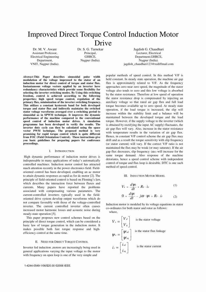
Abstract-This Paper describes sinusoidal pulse widthmodulation of the voltage impressed to the stator of aninduction motor for direct control of torque and stator flux.Instantaneous voltage vectors applied by an inverter haveredundancy characteristics which provide some flexibility forselecting the inverter switching modes. By Using this switchingfreedom, control is achieved according to the followingproperties; high speed torque control, regulation of theprimary flux, minimization of the inverter switching frequency.This utilizes a constant hysteresis band for both developedtorque and stator flux and indirectly maintains the switchedstator voltage waveforms averaged over a switching period tosinusoidal as in SPWM technique. It improves the dynamicperformance of the machine compared to the conventionalspeed control of induction motor drives. A simulationprogramme has been developed to verify the results. Theinverter duty cycle can then be calculated using the spacevector PWM technique. The proposed method is verypromising for rapid torque control which is quite differentfrom FOC (Field Orientation Control). These instructions giveyou basic guidelines for preparing papers for conferenceproceedings.
I. INTRODUCTION
High dynamic performance of induction motor drives isindispensable in many applications of today’s automaticallycontrolled machines. Induction motor control has attractedmuch attention recently in the power electronics field. Field-oriented control has been developed, enabling an ac motorto attain dynamic responses as rapid as for dc motor [2]. Theprinciple of field-oriented control is based on Fleming’s law,which describes the interaction force between fluxes andcurrents. Many papers have reported the problemsassociated with compensating various parameters. Thecurrent-controlled inverters typically used in the field-oriented drive system develop output waveforms which donot compare favorably with those of the voltage-controlledinverter. The current controlled inverter often causesincreased motor harmonic losses and acoustic noise duringsteady-state operation [5].
This paper proposes new control schemes based on theprinciple of direct torque control, which can be considered abasic law of torque generation in the induction motor. Itmakes possible both fast torque response and high-efficiency control at the same time.
II. NEED FOR DIRECT TORQUE CONTROL
Inverter fed induction ,motors are increasingly being used ingeneral applications varying the input voltage to the motorwith frequency on open loop is one of the very simple and
popular methods of speed control. In this method V/F isheld constant. In steady state operation, the machine air gapflux is approximately related to V/F. As the frequencyapproaches zero near zero speed, the magnitude of the statorvoltage also tends to zero and this low voltage is absorbedby the stator resistance. Therefore at low speed of operationthe stator resistance drop is compensated by injecting anauxiliary voltage so that rated air gap flux and full loadtorque becomes available up to zero speed. At steady stateoperation, if the load torque is increased, the slip willincrease within the stability limit and a balance will bemaintained between the developed torque and the loadtorque. However, if the supply voltage to the inverter (whichis obtained by rectifying the input AC supply) fluctuates, theair gap flux will vary. Also, increase in the stator resistancewith temperature results in the variation of air gap flux.Hence, in constant V/F control scheme the air gap flux maydrift and as a result the torque sensitivity with slip frequency(or stator current) will vary. If the correct V/F ratio is notmaintained the flux may be weak (or may saturate). If the airgap flux decreases, slip frequency )1( sω will increase for thesame torque demand. Also response of the machinedetoriates, hence a speed control scheme with independentcontrol of torque and flux loop is desirable. DTC is one suchmethod of speed control.
III. INDUCTION MOTOR MODEL
(1)
(2)
Induction motor is modeled by its voltage equations in statorco-ordinates for both stator and rotor as follows:
where,
is the stator voltage
is the stator flux linkage
is the stator current��
���
�=
��
���
�=
��
���
�=
sq
sds
sq
sds
q
ds
i
ii
V
VV
ψψ
ψ
1-4244-0549-1/06/$20.00 ©2006 IEEE.
rrsor
rosss
iLiL
iLiL
+=+=
ψψ
sse iP
T ×= ψ22
3
rr
osss
L
LiL ψψσ −=
rrs
o
LL
L ψσ2
1 −=
srrs
oe
LL
LPT ψψ
σ×=
22
3
δψψσ
sin22
3sr
rs
o
LL
LP=
( )( )ssem
ssss
IP
T
dtIrV
×=
−=
ψ
ψ
22
3
tsL
EVIs Δ
′−=Δ
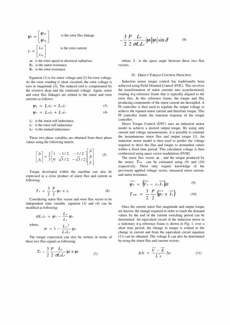
is the rotor flux linkage
is the rotor current
rω is the rotor speed in electrical radian/sec.Rs is the stator resistanceRr is the rotor resistance
Equation (1) is for stator voltage and (2) for rotor voltage.As the rotor winding is short circuited, the rotor voltage iszero in magnitude [3]. The induced emf is compensated bythe resistive drop and the rotational voltage. Again, statorand rotor flux linkages are related to the stator and rotorcurrents as follows:
(3)
(4)
Ls is the stator self inductanceLr is the rotor self inductanceLo is the mutual inductance
These two phase variables are obtained from three phasevalues using the following matrix:
(5)
Torque developed within the machine can also beexpressed as a cross product of stator flux and current asfollowing:
(6)
Considering stator flux vector and rotor flux vector to beindependent state variable, equation (3) and (4) can bemodified as following:
where,
The torque expression can also be written in terms ofthese two flux signals as following:
(7)
(8)
where, � is the space angle between these two fluxvectors.
IV. DIRECT TORQUE CONTROL PRINCIPLE
Induction motor torque control has traditionally beenachieved using Field Oriented Control (FOC). This involvesthe transformation of stator currents into asynchronouslyrotating d-q reference frame that is typically aligned to therotor flux. In this reference frame, the torque and fluxproducing components of the stator current are decoupled. API controller is then used to regulate the output voltage toachieve the reputed stator current and therefore torque. ThisPI controller limits the transient response of the torquecontroller.
Direct Torque Control (DTC) uses an induction motormodel to achieve a desired output torque. By using onlycurrent and voltage measurements, it is possible to estimatethe instantaneous stator flux and output torque [1]. Aninduction motor model is then used to predict the voltagerequired to drive the flux and torque to demanded valueswithin a fixed time period. This calculated voltage is thensynthesized using space vector modulation (SVM).
The stator flux vector, sψ , and the torque produced bythe motor, Tem , can be estimated using (9) and (10)respectively. These only require knowledge of thepreviously applied voltage vector, measured stator current,and stator resistance.
(9)
(10)
Once the current stator flux magnitude and output torqueare known, the change required in order to reach the demandvalues by the end of the current switching period can bedetermined. An equivalent circuit of the induction motor ina stationary d-q reference frame is shown in Fig. 1. over ashort time period, the change in torque is related to thechange in current and from the equivalent circuit equation(11) can be obtained. The voltage E can also be determinedby using the stator flux and current vectors.
(11)
���
�
�
���
�
�
��
���
�−−−
=��
���
�
c
b
a
q
d
f
f
f
f
f
2/32/30
2/12/11
3
2
��
���
�=
��
���
�=
rq
rdr
rq
rdr
i
ii
ψψ
ψ
( )( )( ) tVtrV
EVL
tPT
sIsss
ss
em
Δ⋅=Δ−=Δ
−×′
Δ=Δ
ψ
ψ22
3
Figure 1. Equivalent circuit of an induction motor in a d-q reference frame.
By combining (10) and (11), an expression for the changein torque can be obtained as shown in (12). Equation (9) canalso be rewritten as an expression for the change in thestator flux, as shown in (13).
(12)
(13)
These two equations can be solved to find the smallestvoltage vector, V , required to drive both the torque andflux to the demand values. The required stator voltage canbe calculated by adding on the voltage drop across the statorresistance calculated using the current measured from thelast cycle.
As shown in Fig. 2, the voltage required to drive the errorin the torque and flux to zero is calculated directly. Thecalculated voltage is then synthesized using Space VectorModulation [4]. If the inverter is not capable of generatingthe required voltage then the voltage vector which will drivethe torque and flux towards the demand value is chosen andheld for the complete cycle.
Figure 1. DTC using space vector modulation block diagram.
V. DIRECT TORQUE CONTROL PRINCIPLE
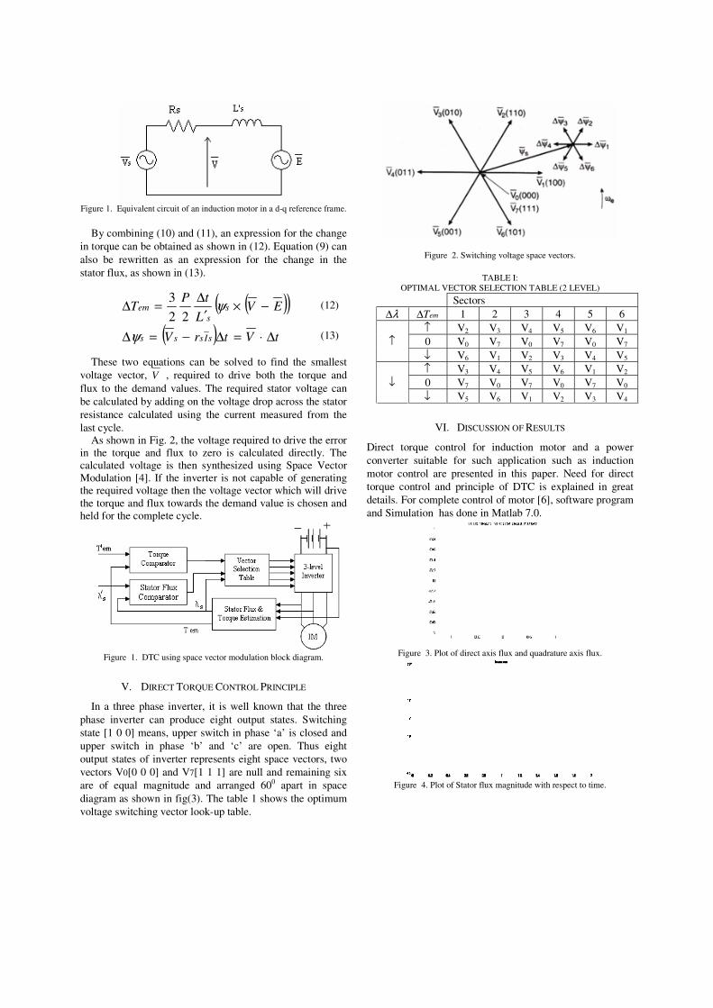
In a three phase inverter, it is well known that the threephase inverter can produce eight output states. Switchingstate [1 0 0] means, upper switch in phase ‘a’ is closed andupper switch in phase ‘b’ and ‘c’ are open. Thus eightoutput states of inverter represents eight space vectors, twovectors V0[0 0 0] and V7[1 1 1] are null and remaining sixare of equal magnitude and arranged 600 apart in spacediagram as shown in fig(3). The table 1 shows the optimumvoltage switching vector look-up table.
Figure 2. Switching voltage space vectors.
TABLE I:OPTIMAL VECTOR SELECTION TABLE (2 LEVEL)
SectorsλΔ emTΔ 1 2 3 4 5 6
↑ V2 V3 V4 V5 V6 V1
0 V0 V7 V0 V7 V0 V7↑↓ V6 V1 V2 V3 V4 V5
↑ V3 V4 V5 V6 V1 V2
0 V7 V0 V7 V0 V7 V0↓↓ V5 V6 V1 V2 V3 V4
VI. DISCUSSION OF RESULTS
Direct torque control for induction motor and a powerconverter suitable for such application such as inductionmotor control are presented in this paper. Need for directtorque control and principle of DTC is explained in greatdetails. For complete control of motor [6], software programand Simulation has done in Matlab 7.0.
Figure 3. Plot of direct axis flux and quadrature axis flux.
Figure 4. Plot of Stator flux magnitude with respect to time.
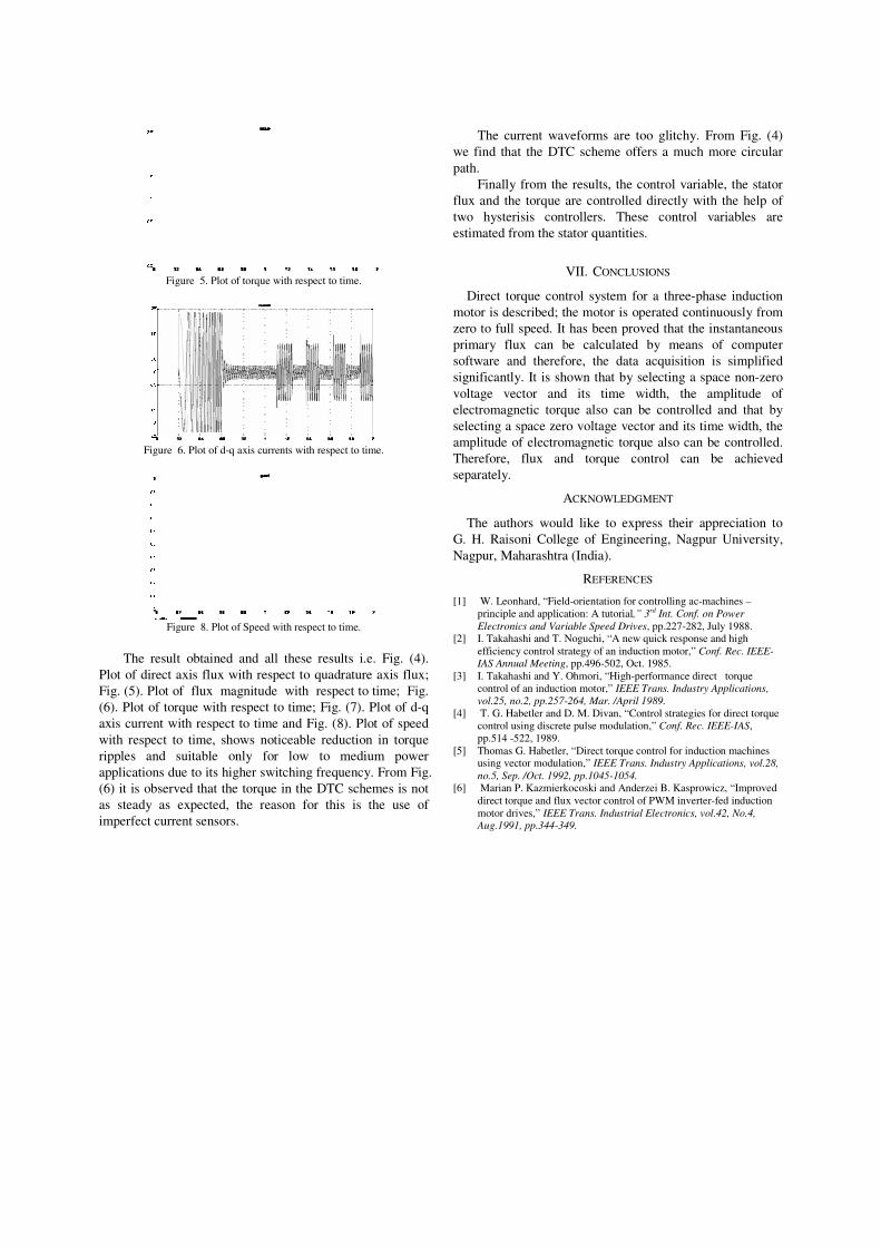
Figure 5. Plot of torque with respect to time.
Figure 6. Plot of d-q axis currents with respect to time.
Figure 8. Plot of Speed with respect to time.
The result obtained and all these results i.e. Fig. (4).Plot of direct axis flux with respect to quadrature axis flux;Fig. (5). Plot of flux magnitude with respect to time; Fig.(6). Plot of torque with respect to time; Fig. (7). Plot of d-qaxis current with respect to time and Fig. (8). Plot of speedwith respect to time, shows noticeable reduction in torqueripples and suitable only for low to medium powerapplications due to its higher switching frequency. From Fig.(6) it is observed that the torque in the DTC schemes is notas steady as expected, the reason for this is the use ofimperfect current sensors.
The current waveforms are too glitchy. From Fig. (4)we find that the DTC scheme offers a much more circularpath.
Finally from the results, the control variable, the statorflux and the torque are controlled directly with the help oftwo hysterisis controllers. These control variables areestimated from the stator quantities.
VII. CONCLUSIONS
Direct torque control system for a three-phase inductionmotor is described; the motor is operated continuously fromzero to full speed. It has been proved that the instantaneousprimary flux can be calculated by means of computersoftware and therefore, the data acquisition is simplifiedsignificantly. It is shown that by selecting a space non-zerovoltage vector and its time width, the amplitude ofelectromagnetic torque also can be controlled and that byselecting a space zero voltage vector and its time width, theamplitude of electromagnetic torque also can be controlled.Therefore, flux and torque control can be achievedseparately.
ACKNOWLEDGMENT
The authors would like to express their appreciation toG. H. Raisoni College of Engineering, Nagpur University,Nagpur, Maharashtra (India).
REFERENCES
[1] W. Leonhard, “Field-orientation for controlling ac-machines –principle and application: A tutorial,” 3rd Int. Conf. on PowerElectronics and Variable Speed Drives, pp.227-282, July 1988.
[2] I. Takahashi and T. Noguchi, “A new quick response and highefficiency control strategy of an induction motor,” Conf. Rec. IEEE-IAS Annual Meeting, pp.496-502, Oct. 1985.
[3] I. Takahashi and Y. Ohmori, “High-performance direct torquecontrol of an induction motor,” IEEE Trans. Industry Applications,vol.25, no.2, pp.257-264, Mar. /April 1989.
[4] T. G. Habetler and D. M. Divan, “Control strategies for direct torquecontrol using discrete pulse modulation,” Conf. Rec. IEEE-IAS,pp.514 -522, 1989.
[5] Thomas G. Habetler, “Direct torque control for induction machinesusing vector modulation,” IEEE Trans. Industry Applications, vol.28,no.5, Sep. /Oct. 1992, pp.1045-1054.
[6] Marian P. Kazmierkocoski and Anderzei B. Kasprowicz, “Improveddirect torque and flux vector control of PWM inverter-fed inductionmotor drives,” IEEE Trans. Industrial Electronics, vol.42, No.4,Aug.1991, pp.344-349.