7μA 1-Cell Fuel Gauge with ModelGauge m5 EZ · ModelGauge m5 EZ algorithm combines the short-term...
24
General Description The MAX17055 is a low 7μA operating current fuel gauge that implements Maxim ModelGauge™ m5 EZ algorithm. ModelGauge m5 EZ makes fuel gauge implementation easy by eliminating battery characterization requirements and simplifying host software interaction. The ModelGauge m5 EZ robust algorithm provides tolerance against battery diversity for most lithium batteries and applications. ModelGauge m5 EZ algorithm combines the short-term accuracy and linearity of a coulomb counter with the long- term stability of a voltage-based fuel gauge, along with temperature compensation to provide industry-leading fuel gauge accuracy. The MAX17055 automatically com- pensates for cell aging, temperature, and discharge rate, and provides accurate state of charge (SOC in %) and remaining capacity in milliampere-hours (mAh). As the battery approaches the critical region near empty, the ModelGauge m5 algorithm invokes a special compensa- tion that eliminates any error. It also provides three meth- ods for reporting the age of the battery: reduction in capac- ity, increase in battery resistance, and cycle odometer. The MAX17055 provides precision measurements of cur- rent, voltage, and temperature. Temperature of the battery pack is measured using an internal temperature mea- surement or external thermistor. A 2-wire I 2 C interface provides access to data and control registers. The MAX17055 is available in a tiny, lead-free 0.4mm pitch 1.4mm x 1.5mm, 9-pin WLP package, and a 2mm x 2.5mm, 10-pin TDFN package. Ordering Information appears at end of data sheet. ModelGauge is a trademark of Maxim Integrated Products, Inc. 19-8726; Rev 0; 1/17 Benefits and Features ● ModelGauge m5 EZ • No Characterization Required for EZ Performance • Robust Against Battery Variation • Eliminates Error Near Empty Voltage • Eliminates Coulomb Counter Drift • Current, Temperature, and Age Compensated • Does Not Require Empty, Full, or Idle States ● Low 7μA Operating Current ● Wide Sense Resistor Range • 1mΩ to 1000mΩ • PCB Metal Sensing + Temperature Compensation ● Supports Li+ and Variants Including LiFePO 4 ● ±1°C Internal Temperature or Thermistor ● Dynamic Power Estimates Power Capability During Discharge ● Time-to-Empty and Time-to-Full Estimation • Constant Power or Constant Current ● Predicts Remaining Capacity Under Theoretical Load ● Precision Measurement System • No Calibration Required ● Alert Indicator for Voltage, SOC, Temperature, Current and 1% SOC Change Applications ● Wearables, Smartwatches ● Smartphones ● Tablets, 2-in-1 Laptops ● Bluetooth Headsets ● Health and Fitness Monitors ● Digital Still, Video, and Action Cameras ● Medical Devices ● Handheld Computers and Terminals ● Wireless Speakers ● Home and Building Automation, Sensors ● Portable Game Players ● Toys MAX17055 7μA 1-Cell Fuel Gauge with ModelGauge m5 EZ
Transcript of 7μA 1-Cell Fuel Gauge with ModelGauge m5 EZ · ModelGauge m5 EZ algorithm combines the short-term...
General DescriptionThe MAX17055 is a low 7μA operating current fuel gauge that implements Maxim ModelGauge™ m5 EZ algorithm. ModelGauge m5 EZ makes fuel gauge implementation easy by eliminating battery characterization requirements and simplifying host software interaction. The ModelGauge m5 EZ robust algorithm provides tolerance against battery diversity for most lithium batteries and applications.ModelGauge m5 EZ algorithm combines the short-term accuracy and linearity of a coulomb counter with the long-term stability of a voltage-based fuel gauge, along with temperature compensation to provide industry-leading fuel gauge accuracy. The MAX17055 automatically com-pensates for cell aging, temperature, and discharge rate, and provides accurate state of charge (SOC in %) and remaining capacity in milliampere-hours (mAh). As the battery approaches the critical region near empty, the ModelGauge m5 algorithm invokes a special compensa-tion that eliminates any error. It also provides three meth-ods for reporting the age of the battery: reduction in capac-ity, increase in battery resistance, and cycle odometer.The MAX17055 provides precision measurements of cur-rent, voltage, and temperature. Temperature of the battery pack is measured using an internal temperature mea-surement or external thermistor. A 2-wire I2C interface provides access to data and control registers.The MAX17055 is available in a tiny, lead-free 0.4mm pitch 1.4mm x 1.5mm, 9-pin WLP package, and a 2mm x 2.5mm, 10-pin TDFN package.
Ordering Information appears at end of data sheet.ModelGauge is a trademark of Maxim Integrated Products, Inc.
19-8726; Rev 0; 1/17
Benefits and Features ModelGauge m5 EZ
• No Characterization Required for EZ Performance• Robust Against Battery Variation• Eliminates Error Near Empty Voltage• Eliminates Coulomb Counter Drift• Current, Temperature, and Age Compensated• Does Not Require Empty, Full, or Idle States
Low 7μA Operating Current Wide Sense Resistor Range
• 1mΩ to 1000mΩ• PCB Metal Sensing + Temperature Compensation
Supports Li+ and Variants Including LiFePO4 ±1°C Internal Temperature or Thermistor Dynamic Power Estimates Power Capability During
Discharge Time-to-Empty and Time-to-Full Estimation
• Constant Power or Constant Current Predicts Remaining Capacity Under Theoretical Load Precision Measurement System
• No Calibration Required Alert Indicator for Voltage, SOC, Temperature,
Current and 1% SOC Change
Applications Wearables, Smartwatches Smartphones Tablets, 2-in-1 Laptops Bluetooth Headsets Health and Fitness Monitors Digital Still, Video, and Action Cameras Medical Devices Handheld Computers and Terminals Wireless Speakers Home and Building Automation, Sensors Portable Game Players Toys
MAX17055 7μA 1-Cell Fuel Gauge with ModelGauge m5 EZ
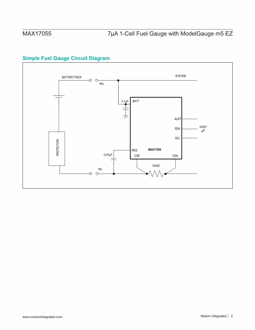
Simple Fuel Gauge Circuit Diagram
REG
CSNCSP
10mΩ
PK+
MAX17055
SDA
SCL
ALRT
HOSTµP
PROT
ECTI
ON
BATTERY PACK SYSTEM
PK-
BATT0.1µF
0.47µF
www.maximintegrated.com Maxim Integrated 2
MAX17055 7μA 1-Cell Fuel Gauge with ModelGauge m5 EZ
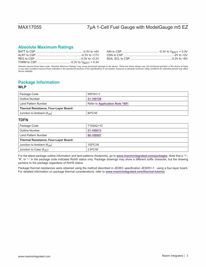
BATT to CSP ...........................................................-0.3V to +6VALRT to CSP .........................................................-0.3V to +17VREG to CSP .........................................................-0.3V to +2.2VTHRM to CSP .......................................... -0.3V to VBATT + 0.3V
AIN to CSP .............................................. -0.3V to VBATT + 0.3VCSN to CSP ...............................................................-2V to +2VSDA, SCL to CSP ....................................................-0.3V to +6V
Absolute Maximum Ratings
Stresses beyond those listed under “Absolute Maximum Ratings” may cause permanent damage to the device. These are stress ratings only, and functional operation of the device at these or any other conditions beyond those indicated in the operational sections of the specifications is not implied. Exposure to absolute maximum rating conditions for extended periods may affect device reliability.
WLP
Package Code W91N1+1Outline Number 21-100129Land Pattern Number Refer to Application Note 1891Thermal Resistance, Four-Layer Board:Junction to Ambient (θJA) 84ºC/W
TDFNPackage Code T102A2+1COutline Number 21-100013Land Pattern Number 90-100007Thermal Resistance, Four-Layer Board:Junction to Ambient (θJA) 102ºC/WJunction to Case (θJC) 2.9ºC/W
Package thermal resistances were obtained using the method described in JEDEC specification JESD51-7, using a four-layer board. For detailed information on package thermal considerations, refer to www.maximintegrated.com/thermal-tutorial.
For the latest package outline information and land patterns (footprints), go to www.maximintegrated.com/packages. Note that a “+”, “#”, or “-” in the package code indicates RoHS status only. Package drawings may show a different suffix character, but the drawing pertains to the package regardless of RoHS status.
Package Information
www.maximintegrated.com Maxim Integrated 3
MAX17055 7μA 1-Cell Fuel Gauge with ModelGauge m5 EZ
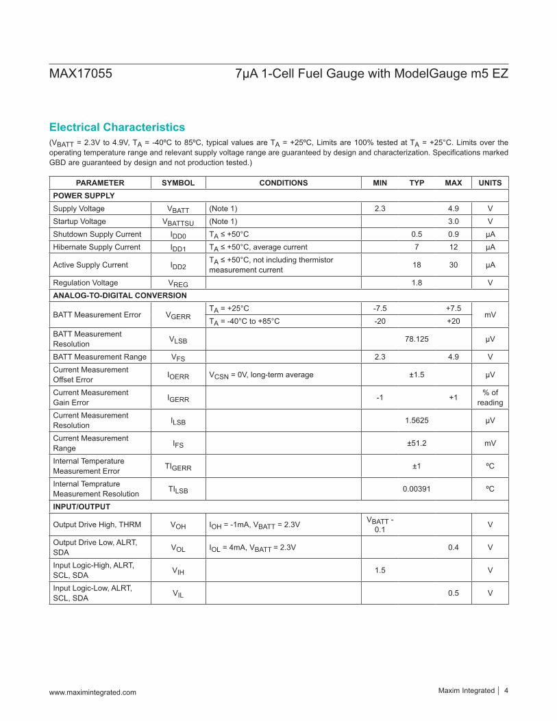
(VBATT = 2.3V to 4.9V, TA = -40ºC to 85ºC, typical values are TA = +25ºC, Limits are 100% tested at TA = +25°C. Limits over the operating temperature range and relevant supply voltage range are guaranteed by design and characterization. Specifications marked GBD are guaranteed by design and not production tested.)
PARAMETER SYMBOL CONDITIONS MIN TYP MAX UNITS POWER SUPPLY Supply Voltage VBATT (Note 1) 2.3 4.9 V Startup Voltage VBATTSU (Note 1) 3.0 V Shutdown Supply Current IDD0 TA ≤ +50°C 0.5 0.9 μA Hibernate Supply Current IDD1 TA ≤ +50°C, average current 7 12 μA
Active Supply Current IDD2TA ≤ +50°C, not including thermistor measurement current 18 30 μA
Regulation Voltage VREG 1.8 V ANALOG-TO-DIGITAL CONVERSION
BATT Measurement Error VGERRTA = +25°C -7.5 +7.5
mV TA = -40°C to +85°C -20 +20
BATT Measurement Resolution VLSB 78.125 μV
BATT Measurement Range VFS 2.3 4.9 V Current Measurement Offset Error IOERR VCSN = 0V, long-term average ±1.5 μV
Current Measurement Gain Error IGERR -1 +1 % of
reading Current Measurement Resolution ILSB 1.5625 μV
Current Measurement Range IFS ±51.2 mV
Internal Temperature Measurement Error TIGERR ±1 ºC
Internal Temprature Measurement Resolution TILSB 0.00391 ºC
INPUT/OUTPUT
Output Drive High, THRM VOH IOH = -1mA, VBATT = 2.3V VBATT - 0.1 V
Output Drive Low, ALRT, SDA VOL IOL = 4mA, VBATT = 2.3V 0.4 V
Input Logic-High, ALRT, SCL, SDA VIH 1.5 V
Input Logic-Low, ALRT, SCL, SDA VIL 0.5 V
Electrical Characteristics
www.maximintegrated.com Maxim Integrated 4
MAX17055 7μA 1-Cell Fuel Gauge with ModelGauge m5 EZ
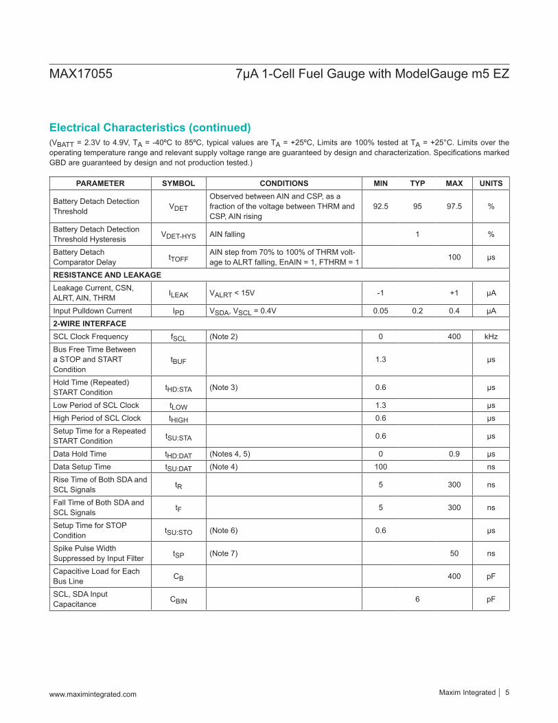
(VBATT = 2.3V to 4.9V, TA = -40ºC to 85ºC, typical values are TA = +25ºC, Limits are 100% tested at TA = +25°C. Limits over the operating temperature range and relevant supply voltage range are guaranteed by design and characterization. Specifications marked GBD are guaranteed by design and not production tested.)
PARAMETER SYMBOL CONDITIONS MIN TYP MAX UNITS
Battery Detach Detection Threshold VDET
Observed between AIN and CSP, as a fraction of the voltage between THRM and CSP, AIN rising
92.5 95 97.5 %
Battery Detach Detection Threshold Hysteresis VDET-HYS AIN falling 1 %
Battery Detach Comparator Delay tTOFF
AIN step from 70% to 100% of THRM volt-age to ALRT falling, EnAIN = 1, FTHRM = 1 100 μs
RESISTANCE AND LEAKAGE Leakage Current, CSN, ALRT, AIN, THRM ILEAK VALRT < 15V -1 +1 μA
Input Pulldown Current IPD VSDA, VSCL = 0.4V 0.05 0.2 0.4 μA 2-WIRE INTERFACE SCL Clock Frequency fSCL (Note 2) 0 400 kHz Bus Free Time Between a STOP and START Condition
tBUF 1.3 μs
Hold Time (Repeated) START Condition tHD:STA (Note 3) 0.6 μs
Low Period of SCL Clock tLOW 1.3 μs High Period of SCL Clock tHIGH 0.6 μs Setup Time for a Repeated START Condition tSU:STA 0.6 μs
Data Hold Time tHD:DAT (Notes 4, 5) 0 0.9 μs Data Setup Time tSU:DAT (Note 4) 100 ns Rise Time of Both SDA and SCL Signals tR 5 300 ns
Fall Time of Both SDA and SCL Signals tF 5 300 ns
Setup Time for STOP Condition tSU:STO (Note 6) 0.6 μs
Spike Pulse Width Suppressed by Input Filter tSP (Note 7) 50 ns
Capacitive Load for Each Bus Line CB 400 pF
SCL, SDA Input Capacitance CBIN 6 pF
Electrical Characteristics (continued)
www.maximintegrated.com Maxim Integrated 5
MAX17055 7μA 1-Cell Fuel Gauge with ModelGauge m5 EZ
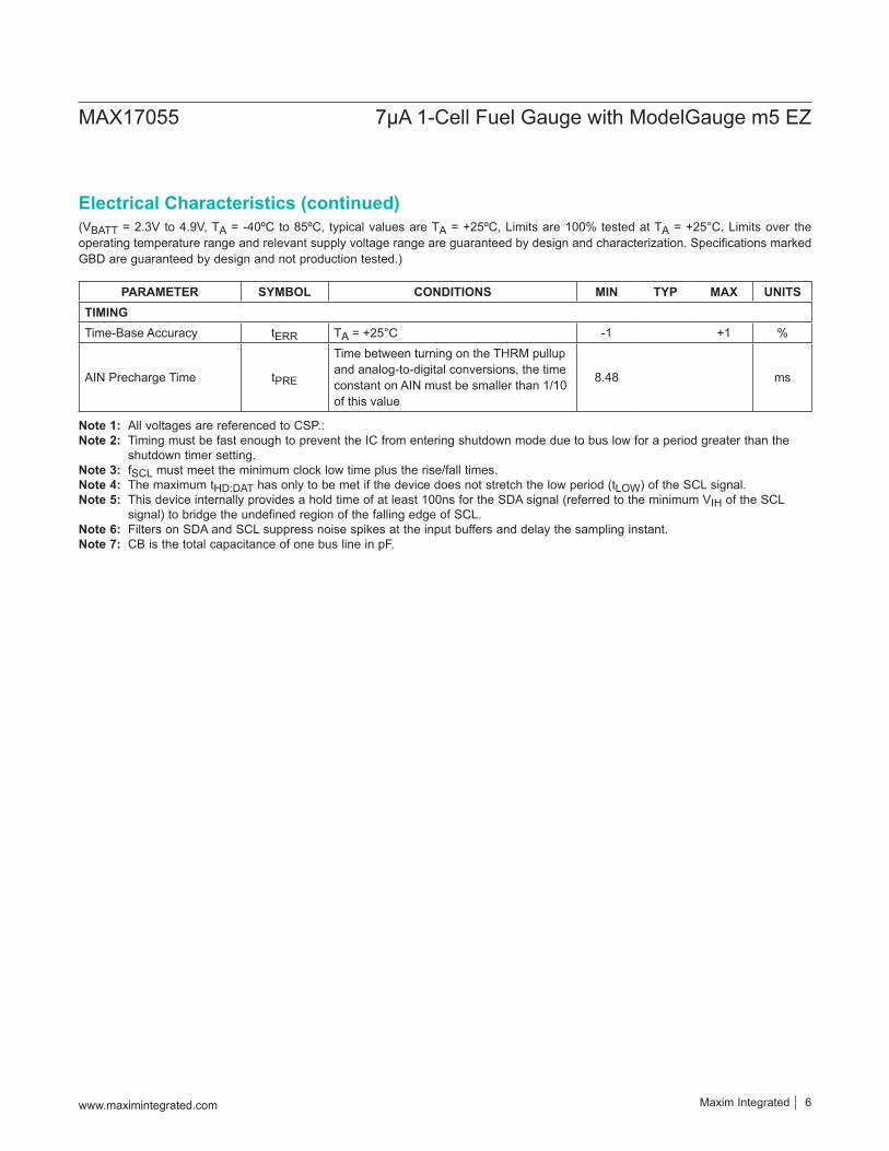
(VBATT = 2.3V to 4.9V, TA = -40ºC to 85ºC, typical values are TA = +25ºC, Limits are 100% tested at TA = +25°C. Limits over the operating temperature range and relevant supply voltage range are guaranteed by design and characterization. Specifications marked GBD are guaranteed by design and not production tested.)
Note 1: All voltages are referenced to CSP.: Note 2: Timing must be fast enough to prevent the IC from entering shutdown mode due to bus low for a period greater than the
shutdown timer setting.Note 3: fSCL must meet the minimum clock low time plus the rise/fall times.Note 4: The maximum tHD:DAT has only to be met if the device does not stretch the low period (tLOW) of the SCL signal.Note 5: This device internally provides a hold time of at least 100ns for the SDA signal (referred to the minimum VIH of the SCL
signal) to bridge the undefined region of the falling edge of SCL.Note 6: Filters on SDA and SCL suppress noise spikes at the input buffers and delay the sampling instant.Note 7: CB is the total capacitance of one bus line in pF.
PARAMETER SYMBOL CONDITIONS MIN TYP MAX UNITS TIMING Time-Base Accuracy tERR TA = +25°C -1 +1 %
AIN Precharge Time tPRE
Time between turning on the THRM pullup and analog-to-digital conversions, the time constant on AIN must be smaller than 1/10 of this value
8.48 ms
Electrical Characteristics (continued)
www.maximintegrated.com Maxim Integrated 6
MAX17055 7μA 1-Cell Fuel Gauge with ModelGauge m5 EZ

Typical Operating Characteristics
0
0.2
0.4
0.6
1 2 3 4
CURR
ENT
(µA)
VOLTAGE (V)
SHUTDOWN CURRENTvs. SUPPLY VOLTAGE
+25°C
toc01
-25°C
+50°C
-5
-4
-3
-2
-1
0
1
2
3
4
5
2.4 3.2 4.0 4.8
ERRR
OR (m
V)
VOLTAGE (V)
VOLTAGE ADC ERROR
+25°C
toc04
-25°C
+50°C
0
1
2
3
4
5
6
7
8
9
10
0 1 2 3 4 5
CURR
ENT
(µA)
VOLTAGE (V)
HIBERNATE CURRENTvs. SUPPLY VOLTAGE
+25°C
toc02
-25°C
+50°C
0
5
10
15
20
25
1 2 3 4
CURR
ENT
(µA)
VOLTAGE (V)
ACTIVE CURRENTvs. SUPPLY VOLTAGE
+25°C
toc03
-25°C
+50°C
Maxim Integrated 7www.maximintegrated.com
MAX17055 7μA 1-Cell Fuel Gauge with ModelGauge m5 EZ
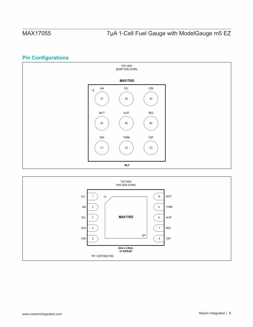
Pin Configurations
AIN
BATT
SCL
MAX17055
WLP
TOP VIEW(BUMP SIDE DOWN)
THRM
A1
B1
C1
A2
B2
C2
A3
B3
C3
CSN
ALRT REG
SDA CSP
N.C.
AIN
SCL MAX17055
TOP VIEW(PAD SIDE DOWN)
CSN
SDA
EP*
1
2
3
4
5
BATT
THRM
ALRT
CSP
REG
2mm x 2.5mm10 TDFN-EP
*EP = EXPOSED PAD
6
7
8
9
10
www.maximintegrated.com Maxim Integrated 8
MAX17055 7μA 1-Cell Fuel Gauge with ModelGauge m5 EZ
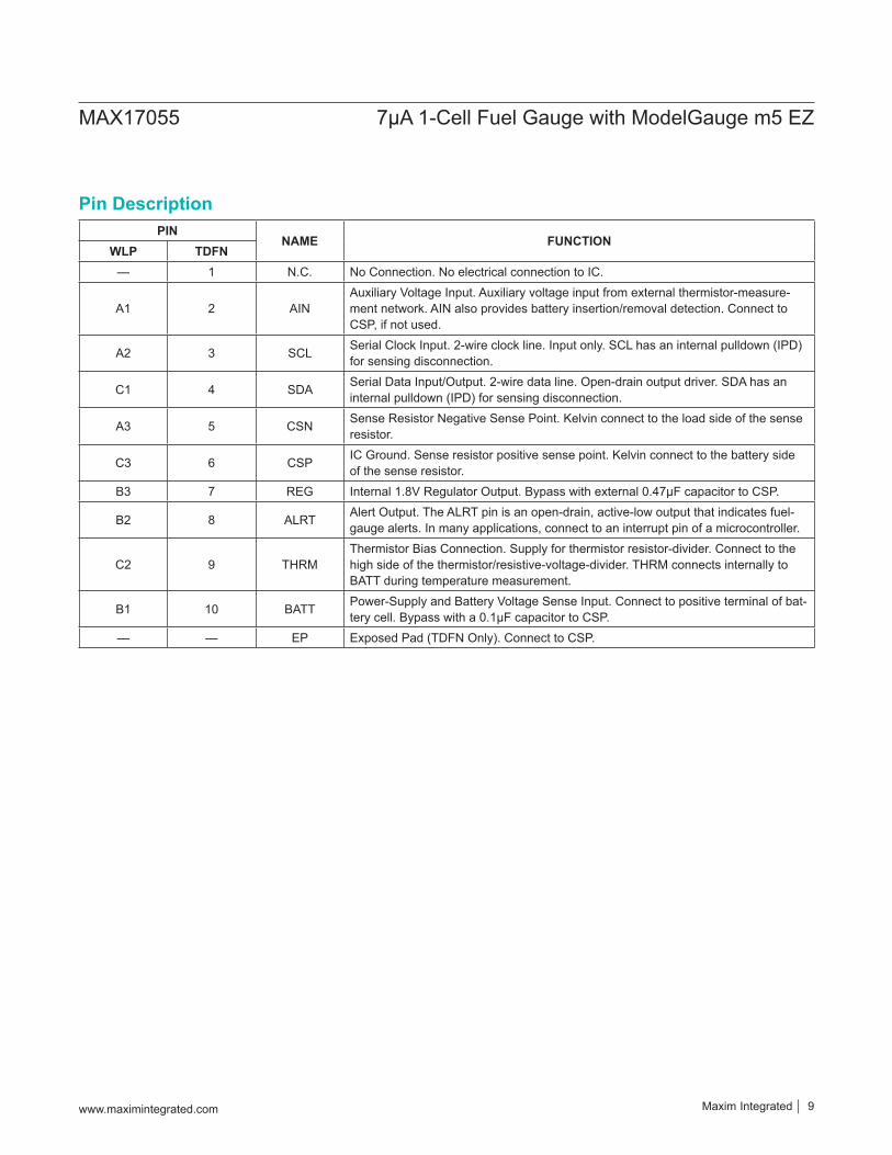
PINNAME FUNCTION
WLP TDFN— 1 N.C. No Connection. No electrical connection to IC.
A1 2 AINAuxiliary Voltage Input. Auxiliary voltage input from external thermistor-measure-ment network. AIN also provides battery insertion/removal detection. Connect to CSP, if not used.
A2 3 SCL Serial Clock Input. 2-wire clock line. Input only. SCL has an internal pulldown (IPD) for sensing disconnection.
C1 4 SDA Serial Data Input/Output. 2-wire data line. Open-drain output driver. SDA has an internal pulldown (IPD) for sensing disconnection.
A3 5 CSN Sense Resistor Negative Sense Point. Kelvin connect to the load side of the sense resistor.
C3 6 CSP IC Ground. Sense resistor positive sense point. Kelvin connect to the battery side of the sense resistor.
B3 7 REG Internal 1.8V Regulator Output. Bypass with external 0.47μF capacitor to CSP.
B2 8 ALRT Alert Output. The ALRT pin is an open-drain, active-low output that indicates fuel-gauge alerts. In many applications, connect to an interrupt pin of a microcontroller.
C2 9 THRMThermistor Bias Connection. Supply for thermistor resistor-divider. Connect to the high side of the thermistor/resistive-voltage-divider. THRM connects internally to BATT during temperature measurement.
B1 10 BATT Power-Supply and Battery Voltage Sense Input. Connect to positive terminal of bat-tery cell. Bypass with a 0.1μF capacitor to CSP.
— — EP Exposed Pad (TDFN Only). Connect to CSP.
Pin Description
www.maximintegrated.com Maxim Integrated 9
MAX17055 7μA 1-Cell Fuel Gauge with ModelGauge m5 EZ
ModelGauge m5 CORE
SCL
SDA
ALRT
CSP
32kHz OSCILLATOR
BATT
CSN
REG
AIN
THRM
12-BIT ADC
REF
MUX
VBATT
INTERNAL TEMPERATURE
SENSOR
SYSPWR
SYSGND
1.8V LDO
OUTIN0.47µF
I2C INTERFACE
MAX17055
RSENSE
0.1µF
PROTECTIONCIRCUIT
THRM ENABLE
10kΩ
10kΩNTC
EP(TDFN ONLY)
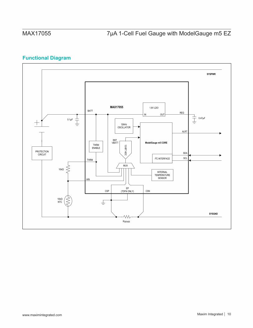
Functional Diagram
www.maximintegrated.com Maxim Integrated 10
MAX17055 7μA 1-Cell Fuel Gauge with ModelGauge m5 EZ
Detailed DescriptionThe MAX17055 is a low power 7μA operating current fuel gauge IC that implements Maxim ModelGauge m5 EZ algorithm. ModelGauge m5 EZ makes fuel gauge imple-mentation easy by eliminating battery characterization requirements and simplifying host software interaction.The MAX17055 measures voltage, current, and tempera-ture to produce fuel gauge results. The MAX17055 uses either an external thermistor or internal die temperature to measure temperature of the battery pack.The ModelGauge m5 EZ robust algorithm provides tolerance against battery diversity. This additional robustness enables simpler implementation for most applications and batteries by avoiding time-consuming battery characterization.The ModelGauge m5 algorithm combines the short-term accuracy and linearity of a coulomb counter with the long-term stability of a voltage-based fuel gauge, along with temperature compensation to provide industry-leading fuel gauge accuracy. The MAX17055 automati-cally compensates for aging, temperature, and discharge rate and provides accurate state of charge (SOC) in milliampere-hours (mAh) or percentage (%) over a wide range of operating conditions. The MAX17055 ensures that fuel gauge error always converges to 0% as the cell approaches empty. The MAX17055 provides accurate estimation of time-to-empty and time-to-full and provides
three methods for reporting the age of the battery: reduc-tion in capacity, increase in battery resistance, and cycle odometer.Communication to the host occurs over standard I2C interface.
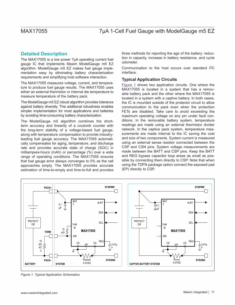
Typical Application CircuitsFigure 1 shows two application circuits. One where the MAX17055 is located in a system that has a remov-able battery pack and the other where the MAX17055 is located in a system with a captive battery. In both cases, the IC is mounted outside of the protector circuit to allow communication to the pack even when the protection FETs are disabled. Take care to avoid exceeding the maximum operating voltage on any pin under fault con-ditions. In the removable battery system, temperature readings are made using an external thermistor divider network. In the captive pack system, temperature mea-surements are made internal to the IC saving the cost and size of two components. System current is measured using an external sense resistor connected between the CSP and CSN pins. System voltage measurements are made between the BATT and CSP pins. Keep the BATT and REG bypass capacitor loop areas as small as pos-sible by connecting them directly to CSP. Note that when using the TDFN package option connect the exposed pad (EP) directly to CSP.
Figure 1. Typical Application Schematics
0.1µF
SCL
SDA
ALRT
CSP
BATT
CSN
AIN
THRM
SYSPWR
SYSGND
MAX17055
REG0.47µF
10kΩ
RSENSE0.010Ω
EP
PACK+
PACK-
THRM
10kΩ NT
C
PROTECTOR
BATTERY SYSTEM
0.1µF
SCL
SDA
ALRT
CSP
BATT
CSN
AIN
THRM
SYSPWR
SYSGND
MAX17055
REG0.47µF
RSENSE0.010Ω
EP
PROTECTOR
CAPTIVE BATTERY SYSTEM
www.maximintegrated.com Maxim Integrated 11
MAX17055 7μA 1-Cell Fuel Gauge with ModelGauge m5 EZ
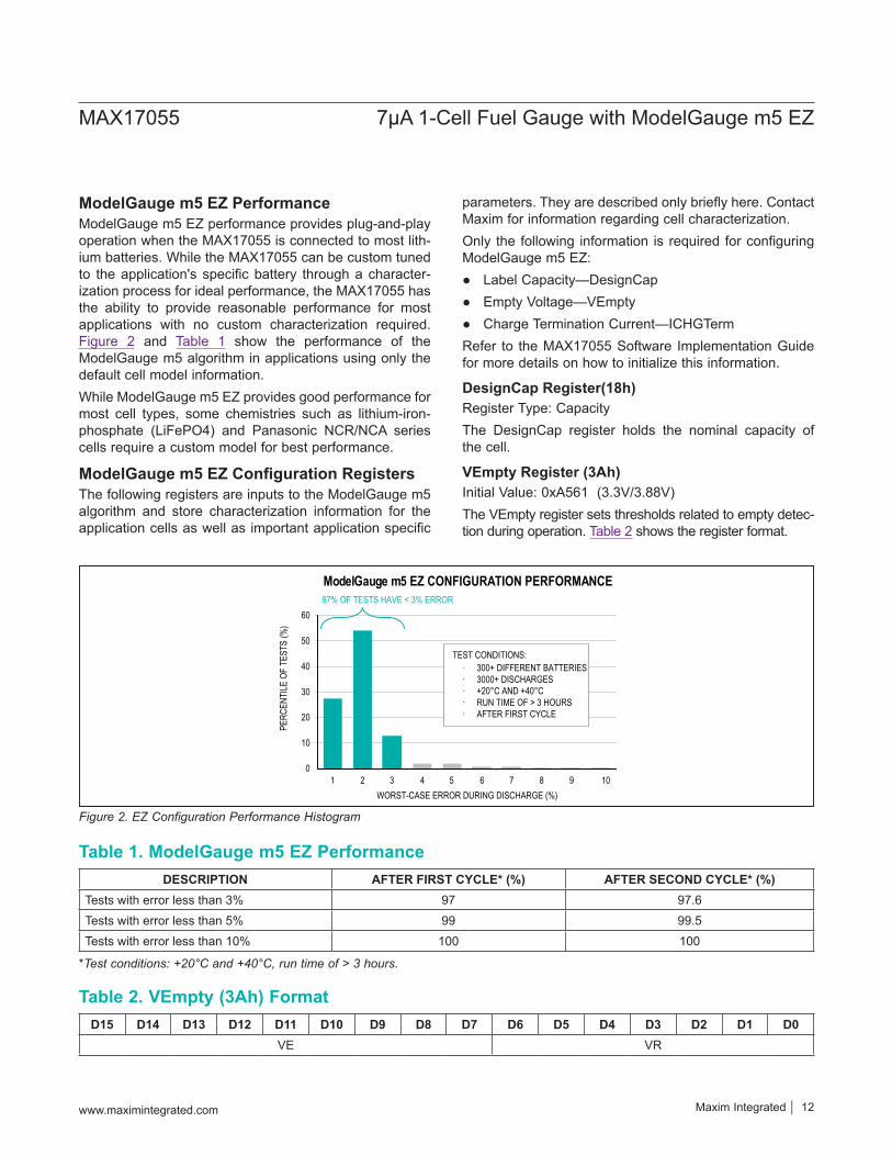
ModelGauge m5 EZ PerformanceModelGauge m5 EZ performance provides plug-and-play operation when the MAX17055 is connected to most lith-ium batteries. While the MAX17055 can be custom tuned to the application's specific battery through a character-ization process for ideal performance, the MAX17055 has the ability to provide reasonable performance for most applications with no custom characterization required. Figure 2 and Table 1 show the performance of the ModelGauge m5 algorithm in applications using only the default cell model information.While ModelGauge m5 EZ provides good performance for most cell types, some chemistries such as lithium-iron-phosphate (LiFePO4) and Panasonic NCR/NCA series cells require a custom model for best performance.
ModelGauge m5 EZ Configuration RegistersThe following registers are inputs to the ModelGauge m5 algorithm and store characterization information for the application cells as well as important application specific
parameters. They are described only briefly here. Contact Maxim for information regarding cell characterization.Only the following information is required for configuring ModelGauge m5 EZ:
Label Capacity—DesignCap Empty Voltage—VEmpty Charge Termination Current—ICHGTerm
Refer to the MAX17055 Software Implementation Guide for more details on how to initialize this information.
DesignCap Register(18h)Register Type: CapacityThe DesignCap register holds the nominal capacity of the cell.
VEmpty Register (3Ah)Initial Value: 0xA561 (3.3V/3.88V)The VEmpty register sets thresholds related to empty detec-tion during operation. Table 2 shows the register format.
DESCRIPTION AFTER FIRST CYCLE* (%) AFTER SECOND CYCLE* (%)Tests with error less than 3% 97 97.6Tests with error less than 5% 99 99.5Tests with error less than 10% 100 100
D15 D14 D13 D12 D11 D10 D9 D8 D7 D6 D5 D4 D3 D2 D1 D0VE VR
Table 1. ModelGauge m5 EZ Performance
Table 2. VEmpty (3Ah) Format
*Test conditions: +20°C and +40°C, run time of > 3 hours.
Figure 2. EZ Configuration Performance Histogram
WORST-CASE ERROR DURING DISCHARGE (%)10987654321
10
0
20
30
40
50
60
PERC
ENTI
LE O
F TE
STS
(%)
ModelGauge m5 EZ CONFIGURATION PERFORMANCE97% OF TESTS HAVE < 3% ERROR
· 300+ DIFFERENT BATTERIES· 3000+ DISCHARGES· +20°C AND +40°C · RUN TIME OF > 3 HOURS· AFTER FIRST CYCLE
TEST CONDITIONS:
www.maximintegrated.com Maxim Integrated 12
MAX17055 7μA 1-Cell Fuel Gauge with ModelGauge m5 EZ
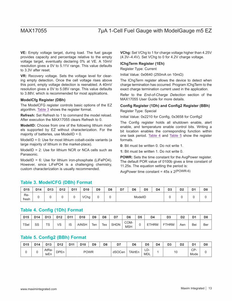
VE: Empty voltage target, during load. The fuel gauge provides capacity and percentage relative to the empty voltage target, eventually declaring 0% at VE. A 10mV resolution gives a 0V to 5.11V range. This value defaults to 3.3V after reset.VR: Recovery voltage. Sets the voltage level for clear-ing empty detection. Once the cell voltage rises above this point, empty voltage detection is reenabled. A 40mV resolution gives a 0V to 5.08V range. This value defaults to 3.88V, which is recommended for most applications.
ModelCfg Register (DBh)The ModelCFG register controls basic options of the EZ algorithm. Table 3 shows the register format.Refresh: Set Refresh to 1 to command the model reload. After execution the MAX17055 clears Refresh to 0.ModelID: Choose from one of the following lithium mod-els supported by EZ without characterization. For the majority of batteries, use ModelID = 0.ModelID = 0: Use for most lithium cobalt-oxide variants (a large majority of lithium in the market-place).ModelID = 2: Use for lithium NCR or NCA cells such as Panasonic.ModelID = 6: Use for lithium iron-phosphate (LiFePO4). However, since LiFePO4 is a challenging chemistry, custom characterization is usually recommended.
VChg: Set VChg to 1 for charge voltage higher than 4.25V (4.3V–4.4V). Set VChg to 0 for 4.2V charge voltage.
IChgTerm Register (1Eh)Register Type: CurrentInitial Value: 0x0640 (250mA on 10mΩ)The IChgTerm register allows the device to detect when charge termination has occurred. Program IChgTerm to the exact charge termination current used in the application. Refer to the End-of-Charge Detection section of the MAX17055 User Guide for more details.
Config Register (1Dh) and Config2 Register (BBh)Register Type: SpecialInitial Value: 0x2210 for Config, 0x3658 for Config2The Config register holds all shutdown enable, alert enable, and temperature enable control bits. Writing a bit location enables the corresponding function within one task period. Table 4 and Table 5 show the register formats.0: Bit must be written 0. Do not write 1.1: Bit must be written 1. Do not write 0.POWR: Sets the time constant for the AvgPower register. The default POR value of 0100b gives a time constant of 11.25s. The equation setting the period is:AvgPower time constant = 45s x 2(POWR-6)
D15 D14 D13 D12 D11 D10 D9 D8 D7 D6 D5 D4 D3 D2 D1 D0Re-
fresh 0 0 0 0 VChg 0 0 ModelID 0 0 0 0
D15 D14 D13 D12 D11 D10 D9 D8 D7 D6 D5 D4 D3 D2 D1 D0
0 0 AtRa-teEn DPEn POWR dSOCen TAlrtEn LD-
MDL 1 10 CP-Mode 0
D15 D14 D13 D12 D11 D10 D9 D8 D7 D6 D5 D4 D3 D2 D1 D0
TSel SS TS VS IS AINSH Ten Tex SHDN COM-MSH 0 ETHRM FTHRM Aen Bei Ber
Table 3. ModelCFG (DBh) Format
Table 5. Config2 (BBh) Format
Table 4. Config (1Dh) Format
www.maximintegrated.com Maxim Integrated 13
MAX17055 7μA 1-Cell Fuel Gauge with ModelGauge m5 EZ
IS (Current ALRT Sticky): When IS = 1, current alerts can only be cleared through software. When IS = 0, cur-rent alerts are cleared automatically when the threshold is no longer exceeded.AtRateEn (AtRate Enable): When this bit is set to 0, AtRate calculations are disabled and registers AtQResidual/AtTTE/AtAvSOC/AtAvCap can be used as general purpose memory.DPEn (Dynamic Power Enable): When this bit is set to 0, Dynamic Power calculations are disabled and registers MaxPeakPower/SusPeakPower/MPPCurrent/SPPCurrent can be used as general purpose memory.CPMode (Constant Power Mode): Set to 1 to enable constant-power mode. If it is set to 0, AtRate/AvgCurrent is used for (At)TTE/(At)QResidual/(At)AvSOC/(At)AvCap. If it is set to 1,
AtRate/AvgCurrent x (AvgVCell
AvgVCell + VEmpty2
) is used for
those calculations.TSel: 0 to use internal die temperature. 1 to use tempera-ture information from thermistor. ETHRM bit should be set to 1 when TSel is 1.Ber: Enable alert on battery removal when the IC is mounted host side. When Ber = 1, a battery-removal con-dition, as detected by the AIN pin voltage, triggers an alert.Bei: Enable alert on battery insertion when the IC is mounted host side. When Bei = 1, a battery-insertion con-dition, as detected by the AIN pin voltage, triggers an alert.Aen (Enable Alert on Fuel-Gauge Outputs): When Aen = 1, violation of any of the alert threshold register values by temperature, voltage, or SOC triggers an alert. This bit affects the ALRT pin operation only. The Smx, Smn, Tmx, Tmn, Vmx, Vmn, Imx, and Imn bits of the Status register (00h) are not disabled.FTHRM (Force Thermistor Bias Switch): This allows the host to control the bias of the thermistor switch or enable fast detection of battery removal. Set FTHRM = 1 to always enable the thermistor bias switch. With a stan-dard 10kΩ thermistor, this adds an additional ~200μA to the current drain of the circuit.ETHRM (Enable Thermistor): Set to logic 1 to enable the automatic THRM output bias and AIN measurement.COMMSH: (Communication Shutdown): Set to logic 1 to force the device to enter shutdown mode if both SDA and SCL are held low for more than timeout of the ShdnTimer register. This also configures the device to wake up on a rising edge of any communication. Note
that if COMMSH and AINSH are both set to 0, the device wakes up an edge of any of the SDA or SCL pins. See the Modes of Operation section.SHDN (Shutdown): Write this bit to logic 1 to force a shutdown of the device after timeout of the ShdnTimer register (default 45s delay). SHDN is reset to 0 at power-up and upon exiting shutdown mode. To command shut-down within 45s, first write HibCFG = 0x0000 to enter active mode.Tex (Temperature External): When set to 1, the fuel gauge requires external temperature measurements to be written from the host. When set to 0, the IC's own mea-surements as used as selected by Config.TSEL.Ten (Enable Temperature Channel): Set to 1 and set ETHRM or FTHRM to 1 to enable temperature measure-ments selected by Config.TSel.AINSH (AIN Pin Shutdown): Set to 1 to enable device shutdown when the IC is mounted host side and the bat-tery is removed. The IC enters shutdown if the AIN pin remains high (AIN > VTHRM - VDET) for longer than the timeout of the ShdnTimer register. This also configures the device to wake up when AIN is pulled low on cell insertion. Note that if COMMSH and AINSH are both set to 0, the device wakes up an edge of any of the SDA or SCL pins.VS (Voltage ALRT Sticky): When VS = 1, voltage alerts can only be cleared through software. When VS = 0, volt-age alerts are cleared automatically when the threshold is no longer exceeded.TS (Temperature ALRT Sticky): When TS = 1, tempera-ture alerts can only be cleared through software. When TS = 0, temperature alerts are cleared automatically when the threshold is no longer exceeded.SS (SOC ALRT Sticky): When SS = 1, SOC alerts can only be cleared through software. When SS = 0, SOC alerts are cleared automatically when the threshold is no longer exceeded.TAlrten (Temperature Alert Enable): Set this bit to 1 to enable temperature based alerts. Write this bit to 0 to dis-able temperature alerts. This bit is set to 1 at power-up.dSOCen (SOC Change Alert Enable): Set this bit to 1 to enable alert output with the Status.dSOCi bit function. Write this bit to 0 to disable alert output with the Status.dSOCi bit. This bit is set to 0 at power-up.LDMdl: Host sets this bit to 1 in order to initiate firmware to finish processing a newly loaded model. Firmware clears this bit to zero to indicate that model loading is finished.
www.maximintegrated.com Maxim Integrated 14
MAX17055 7μA 1-Cell Fuel Gauge with ModelGauge m5 EZ
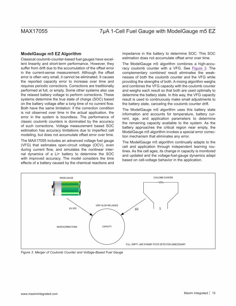
ModelGauge m5 EZ AlgorithmClassical coulomb-counter-based fuel gauges have excel-lent linearity and short-term performance. However, they suffer from drift due to the accumulation of the offset error in the current-sense measurement. Although the offset error is often very small, it cannot be eliminated. It causes the reported capacity error to increase over time and requires periodic corrections. Corrections are traditionally performed at full, or empty. Some other systems also use the relaxed battery voltage to perform corrections. These systems determine the true state of charge (SOC) based on the battery voltage after a long time of no current flow. Both have the same limitation: if the correction condition is not observed over time in the actual application, the error in the system is boundless. The performance of classic coulomb counters is dominated by the accuracy of such corrections. Voltage measurement based SOC estimation has accuracy limitations due to imperfect cell modeling, but does not accumulate offset error over time.The MAX17055 includes an advanced voltage fuel gauge (VFG) that estimates open-circuit voltage (OCV), even during current flow, and simulates the nonlinear inter-nal dynamics of a Li+ battery to determine the SOC with improved accuracy. The model considers the time effects of a battery caused by the chemical reactions and
impedance in the battery to determine SOC. This SOC estimation does not accumulate offset error over time.The ModelGauge m5 algorithm combines a high-accu-racy coulomb counter with a VFG. See Figure 3. The complementary combined result eliminates the weak-nesses of both the coulomb counter and the VFG while providing the strengths of both. A mixing algorithm weighs and combines the VFG capacity with the coulomb counter and weighs each result so that both are used optimally to determine the battery state. In this way, the VFG capacity result is used to continuously make small adjustments to the battery state, canceling the coulomb counter drift.The ModelGauge m5 algorithm uses this battery state information and accounts for temperature, battery cur-rent, age, and application parameters to determine the remaining capacity available to the system. As the battery approaches the critical region near empty, the ModelGauge m5 algorithm invokes a special error correc-tion mechanism that eliminates any error. The ModelGauge m5 algorithm continually adapts to the cell and application through independent learning rou-tines. As the cell ages, its change in capacity is monitored and updated and the voltage-fuel-gauge dynamics adapt based on cell-voltage behavior in the application.
Figure 3. Merger of Coulomb Counter and Voltage-Based Fuel Gauge
COULOMB COUNTER
CAPACITY
ΔQ Ʃ
FULL, EMPTY, AND STANDBY STATE DETECTION UNNECESSARY
MODELGAUGE
Δ% SOC
MICROCORRECTIONS
VERY SLOW INFLUENCE
www.maximintegrated.com Maxim Integrated 15
MAX17055 7μA 1-Cell Fuel Gauge with ModelGauge m5 EZ

Application NotesRefer to the following application notes for additional ref-erence material:
Application Note 6358: MAX17055 User Guide• Documents full register set• More details about ModelGauge m5 algorithm• Discusses additional applications
Application Note 6365: MAX17055 Software Imple-mentation Guide• Guidelines for Software Drivers including example
code
Standard Register FormatsUnless otherwise stated during a given register's descrip-tion, all IC registers follow the same format depending on the type of register. See Table 6 for the resolution and range of any register described hereafter. Note that cur-rent and capacity values are displayed as a voltage and must be divided by the sense resistor to determine Amps or Amp-hours.
ModelGauge m5 Algorithm Output RegistersThe following registers are outputs from the ModelGauge m5 algorithm. The values in these registers become valid 351ms after the MAX17055 is configured.
RepCap Register (05h)Register Type: CapacityRepCap or reported remaining capacity in mAh. This register is protected from making sudden jumps during load changes.
RepSOC Register (06h)Register Type: PercentageRepSOC is the reported state-of-charge percentage out-put for use by the application GUI.
FullCapRep Register (10h)Register Type: CapacityThis register reports the full capacity that goes with RepCap, generally used for reporting to the user. A new full-capacity value is calculated at the end of every charge cycle in the application.
TTE Register (11h)Register Type: TimeThe TTE register holds the estimated time to empty for the application under present temperature and load conditions.
REGISTER TYPE LSB SIZE MINIMUM
VALUEMAXIMUM
VALUE NOTES
Capacity 5.0μVH/ RSENSE 0.0μVH 327.675mVH/ RSENSE
Equivalent to 0.5mA with a 0.010Ω sense resistor.
Percentage 1/256% 0.0% 255.9961% 1% LSb when reading only the upper byte.Voltage 1.25mV/16 0.0V 5.11992V
Current 1.5625μV/ RSENSE
-51.2mV/ RSENSE
51.1984mV/ RSENSE
Signed 2's complement format. Equivalent to 156.25μA with a 0.010Ω sense resistor.
Temperature 1/256°C -128.0°C 127.996°C Signed 2's complement format. 1°C LSb when reading only the upper byte.
Resistance 1/4096Ω 0.0Ω 15.99976Ω Time 5.625s 0.0s 102.3984h
Special Format details are included with the register description.
Table 6. ModelGauge Register Standard Resolutions
www.maximintegrated.com Maxim Integrated 16
MAX17055 7μA 1-Cell Fuel Gauge with ModelGauge m5 EZ
TTF Register (20h)Register Type: TimeThe TTF register holds the estimated time to full for the application under present conditions. The TTF value is determined by learning the constant current and constant voltage portions of the charge cycle based on experience of prior charge cycles. Time to full is then estimated by comparing present charge current to the charge termina-tion current. Operation of the TTF register assumes all charge profiles are consistent in the application.
Cycles Register (17h)Register Type: SpecialThe Cycles register maintains a total count of the number of charge/discharge cycles of the cell that have occurred. The result is stored as a percentage of a full cycle. For example, a full charge/discharge cycle results in the Cycles register incrementing by 100%. The Cycles register accumulates fractional or whole cycles. For example, if a battery is cycled 10% x 10 times, then it tracka 100% of one cycle.The Cycles register has a full range of 0 to 655.35 cycles with a 1% LSb.
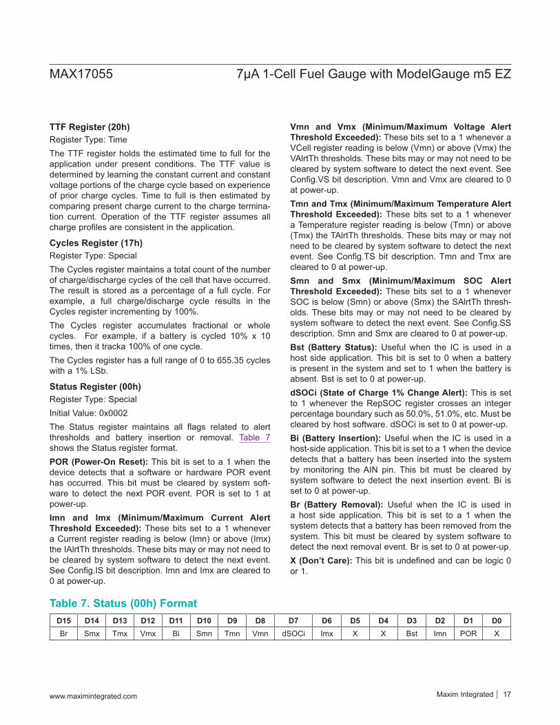
Status Register (00h)Register Type: SpecialInitial Value: 0x0002The Status register maintains all flags related to alert thresholds and battery insertion or removal. Table 7 shows the Status register format.POR (Power-On Reset): This bit is set to a 1 when the device detects that a software or hardware POR event has occurred. This bit must be cleared by system soft-ware to detect the next POR event. POR is set to 1 at power-up.Imn and Imx (Minimum/Maximum Current Alert Threshold Exceeded): These bits set to a 1 whenever a Current register reading is below (Imn) or above (Imx) the IAlrtTh thresholds. These bits may or may not need to be cleared by system software to detect the next event. See Config.IS bit description. Imn and Imx are cleared to 0 at power-up.
Vmn and Vmx (Minimum/Maximum Voltage Alert Threshold Exceeded): These bits set to a 1 whenever a VCell register reading is below (Vmn) or above (Vmx) the VAlrtTh thresholds. These bits may or may not need to be cleared by system software to detect the next event. See Config.VS bit description. Vmn and Vmx are cleared to 0 at power-up.Tmn and Tmx (Minimum/Maximum Temperature Alert Threshold Exceeded): These bits set to a 1 whenever a Temperature register reading is below (Tmn) or above (Tmx) the TAlrtTh thresholds. These bits may or may not need to be cleared by system software to detect the next event. See Config.TS bit description. Tmn and Tmx are cleared to 0 at power-up.Smn and Smx (Minimum/Maximum SOC Alert Threshold Exceeded): These bits set to a 1 whenever SOC is below (Smn) or above (Smx) the SAlrtTh thresh-olds. These bits may or may not need to be cleared by system software to detect the next event. See Config.SS description. Smn and Smx are cleared to 0 at power-up.Bst (Battery Status): Useful when the IC is used in a host side application. This bit is set to 0 when a battery is present in the system and set to 1 when the battery is absent. Bst is set to 0 at power-up.dSOCi (State of Charge 1% Change Alert): This is set to 1 whenever the RepSOC register crosses an integer percentage boundary such as 50.0%, 51.0%, etc. Must be cleared by host software. dSOCi is set to 0 at power-up.Bi (Battery Insertion): Useful when the IC is used in a host-side application. This bit is set to a 1 when the device detects that a battery has been inserted into the system by monitoring the AIN pin. This bit must be cleared by system software to detect the next insertion event. Bi is set to 0 at power-up.Br (Battery Removal): Useful when the IC is used in a host side application. This bit is set to a 1 when the system detects that a battery has been removed from the system. This bit must be cleared by system software to detect the next removal event. Br is set to 0 at power-up.X (Don’t Care): This bit is undefined and can be logic 0 or 1.
D15 D14 D13 D12 D11 D10 D9 D8 D7 D6 D5 D4 D3 D2 D1 D0Br Smx Tmx Vmx Bi Smn Tmn Vmn dSOCi Imx X X Bst Imn POR X
Table 7. Status (00h) Format
www.maximintegrated.com Maxim Integrated 17
MAX17055 7μA 1-Cell Fuel Gauge with ModelGauge m5 EZ
Analog MeasurementsThe MAX17055 monitors voltage, current, and tempera-ture. This information is provided to the fuel guage algo-rithm to predict cell capacity and also made available to the user.
Voltage MeasurementThe MAX17055 monitors the battery voltage at BATT. See the following sections for the voltage register description details.
VCell Register (09h)Register Type: VoltageVCell reports the voltage measured between BATT and CSP.
AvgVCell Register (19h)Register Type: VoltageThe AvgVCell register reports an average of the VCell register readings.
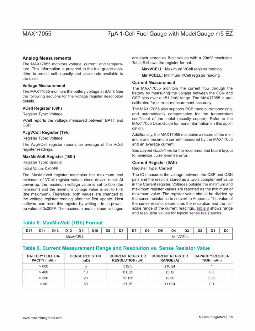
MaxMinVolt Register (1Bh)Register Type: SpecialInitial Value: 0x00FFThe MaxMinVolt register maintains the maximum and minimum of VCell register values since device reset. At power-up, the maximum voltage value is set to 00h (the minimum) and the minimum voltage value is set to FFh (the maximum). Therefore, both values are changed to the voltage register reading after the first update. Host software can reset this register by writing it to its power-up value of 0x00FF. The maximum and minimum voltages
are each stored as 8-bit values with a 20mV resolution. Table 8 shows the register format. MaxVCELL: Maximum VCell register reading MinVCELL: Minimum VCell register reading
Current MeasurementThe MAX17055 monitors the current flow through the battery by measuring the voltage between the CSN and CSP pins over a ±51.2mV range. The MAX17055 is pre-calibrated for current-measurement accuracy.The MAX17055 also supports PCB trace current-sensing, and automatically compensates for the temperature coefficient of the metal (usually copper). Refer to the MAX17055 User Guide for more information on this appli-cation.Additionally, the MAX17055 maintains a record of the min-imum and maximum current measured by the MAX17055 and an average current.See Layout Guidelines for the recommended board layout to minimize current-sense error.
Current Register (0Ah)Register Type: CurrentThe IC measures the voltage between the CSP and CSN pins and the result is stored as a two’s complement value in the Current register. Voltages outside the minimum and maximum register values are reported as the minimum or maximum value. The register value should be divided by the sense resistance to convert to Amperes. The value of the sense resistor determines the resolution and the full-scale range of the current readings. Table 9 shows range and resolution values for typical sense resistances.
D15 D14 D13 D12 D11 D10 D9 D8 D7 D6 D5 D4 D3 D2 D1 D0MaxVCELL MinVCELL
BATTERY FULL CA-PACITY (mAh)
SENSE RESISTOR (mΩ)
CURRENT REGISTER RESOLUTION (μA)
CURRENT REGISTER RANGE (A)
CAPACITY RESOLU-TION (mAh)
> 800 5 312.5 ±10.24 1> 400 10 156.25 ±5.12 0.5> 200 20 78.125 ±2.56 0.25> 80 50 31.25 ±1.024 0.1
Table 8. MaxMinVolt (1Bh) Format
Table 9. Current Measurement Range and Resolution vs. Sense Resistor Value
www.maximintegrated.com Maxim Integrated 18
MAX17055 7μA 1-Cell Fuel Gauge with ModelGauge m5 EZ
AvgCurrent Register (0Bh)Register Type: CurrentThe AvgCurrent register reports an average of Current register readings.
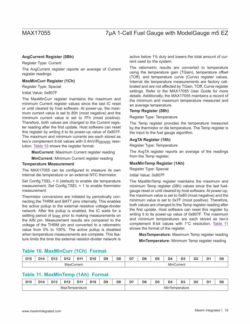
MaxMinCurr Register (1Ch)Register Type: SpecialInitial Value: 0x807FThe MaxMinCurr register maintains the maximum and minimum Current register values since the last IC reset or until cleared by host software. At power-up, the maxi-mum current value is set to 80h (most negative) and the minimum current value is set to 7Fh (most positive). Therefore, both values are changed to the Current regis-ter reading after the first update. Host software can reset this register by writing it to its power-up value of 0x807F. The maximum and minimum currents are each stored as two’s complement 8-bit values with 0.4mV/RSENSE reso-lution. Table 10 shows the register format. MaxCurrent: Maximum Current register reading MinCurrent: Minimum Current register readingTemperature MeasurementThe MAX17055 can be configured to measure its own internal die temperature or an external NTC thermistor. Set Config.TSEL = 0 (default) to enable die temperature measurement. Set Config.TSEL = 1 to enable thermistor measurement.Thermistor conversions are initiated by periodically con-necting the THRM and BATT pins internally. This enables the active pullup to the external resistive voltage-divider network. After the pullup is enabled, the IC waits for a settling period of tPRE prior to making measurements on the AIN pin. Measurement results are compared to the voltage of the THRM pin and converted to a ratiometric value from 0% to 100%. The active pullup is disabled when temperature measurements are complete. This fea-ture limits the time the external resistor-divider network is
active below 1% duty and lowers the total amount of cur-rent used by the system.The ratiometric results are converted to temperature using the temperature gain (TGain), temperature offset (TOff), and temperature curve (Curve) register values. Internal die temperature measurements are factory cali-brated and are not affected by TGain, TOff, Curve register settings. Refer to the MAX17055 User Guide for more details. Additionally, the MAX17055 maintains a record of the minimum and maximum temperature measured and an average temperature.Temp Register (08h)Register Type: TemperatureThe Temp register provides the temperature measured by the thermistor or die temperature. The Temp register is the input to the fuel gauge algorithm.
AvgTA Register (16h)Register Type: TemperatureThe AvgTA register reports an average of the readings from the Temp register.
MaxMinTemp Register (1Ah)Register Type: SpecialInitial Value: 0x807FThe MaxMinTemp register maintains the maximum and minimum Temp register (08h) values since the last fuel-gauge reset or until cleared by host software. At power-up, the maximum value is set to 0x80 (most negative) and the minimum value is set to 0x7F (most positive). Therefore, both values are changed to the Temp register reading after the first update. Host software can reset this register by writing it to its power-up value of 0x807F. The maximum and minimum temperatures are each stored as two’s complement 8-bit values with 1°C resolution. Table 11 shows the format of the register. MaxTemperature: Maximum Temp register reading MinTemperature: Minimum Temp register reading
D15 D14 D13 D12 D11 D10 D9 D8 D7 D6 D5 D4 D3 D2 D1 D0MaxCurrent MinCurrent
D15 D14 D13 D12 D11 D10 D9 D8 D7 D6 D5 D4 D3 D2 D1 D0MaxTemperature MinTemperature
Table 10. MaxMinCurr (1Ch) Format
Table 11. MaxMinTemp (1Ah) Format
www.maximintegrated.com Maxim Integrated 19
MAX17055 7μA 1-Cell Fuel Gauge with ModelGauge m5 EZ
DieTemp Register (034h)Register Type: TemperatureThe DieTemp register provides the internal die tempera-ture measurement. If Config.TSel = 0, DieTemp and Temp registers have the value of the die temperature.
Power Register (B1h)Instant power calculation from immediate current and voltage. The LSB is 0.8mW with a 10mΩ sense resistor.
AvgPower Register (B3h)Filtered average power from the power register. LSB is 0.8mW with a 10mΩ sense resistor.
Alert FunctionThe Alert Threshold registers allow interrupts to be gener-ated by detecting a high or low voltage, current, tempera-ture, or state of charge. Interrupts are generated on the ALRT pin open-drain output driver. An external pullup is required to generate a logic-high signal. Alerts can be trig-gered by any of the following conditions:
Battery removal: (VAIN > VTHRM - VDET) and battery removal detection enabled (Ber = 1).
Battery insertion: (VAIN < VTHRM - VDET-HYS) and battery insertion detection enabled (Bei = 1).
Over/undervoltage: VAlrtTr register threshold violation (upper or lower) and alerts enabled (Aen = 1).
Over/undertemperature: TAlrtTr register threshold vio-lation (upper or lower) and alerts enabled (Aen = 1).
Over/undercurrent: IAlrtTr register threshold violation (upper or lower) and alerts enabled (Aen = 1).
Over/under SOC: SAlrtTr register threshold violation (upper or lower) and alerts enabled (Aen = 1).
1% SOC change: RepSOC register bit d8 (1% bit) changed (dSOCen = 1).
To prevent false interrupts, the threshold registers should be initialized before setting the Aen bit. Alerts generated by battery insertion or removal can only be reset by clear-ing the corresponding bit in the Status (00h) register. Alerts generated by a threshold-level violation can be configured to be cleared only by software, or cleared automatically when the threshold level is no longer vio-lated. See the Config (1Dh) and Config2 (BBh) register descriptions for details of the alert function configuration.
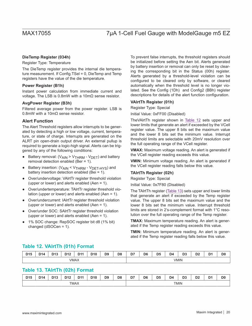
VAlrtTh Register (01h)Register Type: SpecialInitial Value: 0xFF00 (Disabled)TheVAlrtTh register shown in Table 12 sets upper and lower limits that generate an alert if exceeded by the VCell register value. The upper 8 bits set the maximum value and the lower 8 bits set the minimum value. Interrupt threshold limits are selectable with 20mV resolution over the full operating range of the VCell register.VMAX: Maximum voltage reading. An alert is generated if the VCell register reading exceeds this value.VMIN: Minimum voltage reading. An alert is generated if the VCell register reading falls below this value.
TAlrtTh Register (02h)Register Type: SpecialInitial Value: 0x7F80 (Disabled)The TAlrtTh register (Table 13) sets upper and lower limits that generate an alert if exceeded by the Temp register value. The upper 8 bits set the maximum value and the lower 8 bits set the minimum value. Interrupt threshold limits are stored in 2’s-complement format with 1°C reso-lution over the full operating range of the Temp register.TMAX: Maximum temperature reading. An alert is gener-ated if the Temp register reading exceeds this value.TMIN: Minimum temperature reading. An alert is gener-ated if the Temp register reading falls below this value.
D15 D14 D13 D12 D11 D10 D9 D8 D7 D6 D5 D4 D3 D2 D1 D0VMAX VMIN
D15 D14 D13 D12 D11 D10 D9 D8 D7 D6 D5 D4 D3 D2 D1 D0TMAX TMIN
Table 12. VAlrtTh (01h) Format
Table 13. TAlrtTh (02h) Format
www.maximintegrated.com Maxim Integrated 20
MAX17055 7μA 1-Cell Fuel Gauge with ModelGauge m5 EZ
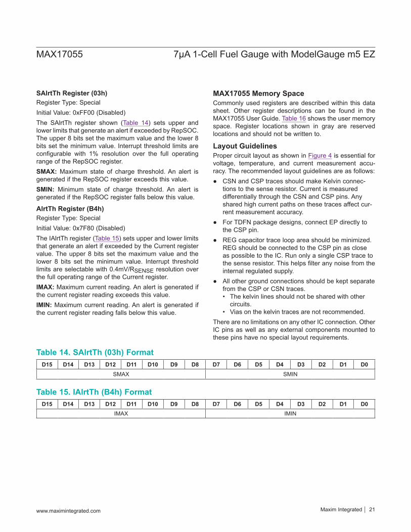
SAlrtTh Register (03h)Register Type: SpecialInitial Value: 0xFF00 (Disabled)The SAlrtTh register shown (Table 14) sets upper and lower limits that generate an alert if exceeded by RepSOC. The upper 8 bits set the maximum value and the lower 8 bits set the minimum value. Interrupt threshold limits are configurable with 1% resolution over the full operating range of the RepSOC register.SMAX: Maximum state of charge threshold. An alert is generated if the RepSOC register exceeds this value.SMIN: Minimum state of charge threshold. An alert is generated if the RepSOC register falls below this value.
AlrtTh Register (B4h)Register Type: SpecialInitial Value: 0x7F80 (Disabled)The IAlrtTh register (Table 15) sets upper and lower limits that generate an alert if exceeded by the Current register value. The upper 8 bits set the maximum value and the lower 8 bits set the minimum value. Interrupt threshold limits are selectable with 0.4mV/RSENSE resolution over the full operating range of the Current register.IMAX: Maximum current reading. An alert is generated if the current register reading exceeds this value.IMIN: Maximum current reading. An alert is generated if the current register reading falls below this value.
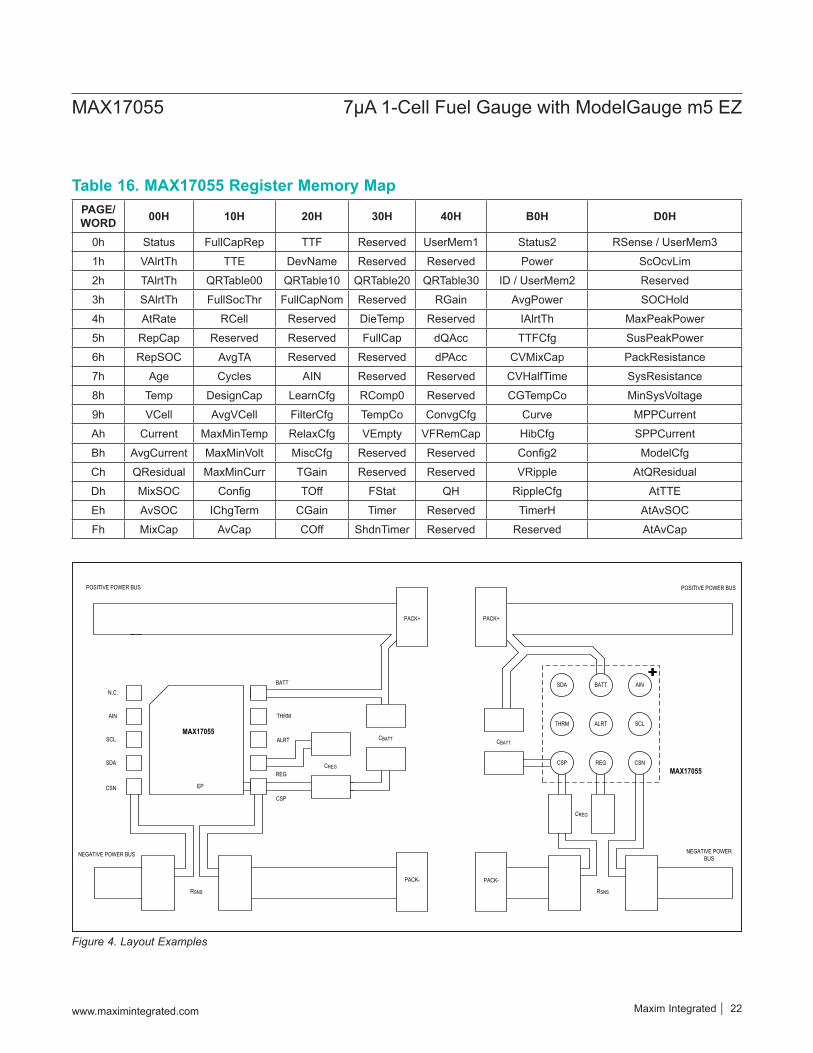
MAX17055 Memory SpaceCommonly used registers are described within this data sheet. Other register descriptions can be found in the MAX17055 User Guide. Table 16 shows the user memory space. Register locations shown in gray are reserved locations and should not be written to.
Layout GuidelinesProper circuit layout as shown in Figure 4 is essential for voltage, temperature, and current measurement accu-racy. The recommended layout guidelines are as follows:
CSN and CSP traces should make Kelvin connec-tions to the sense resistor. Current is measured differentially through the CSN and CSP pins. Any shared high current paths on these traces affect cur-rent measurement accuracy.
For TDFN package designs, connect EP directly to the CSP pin.
REG capacitor trace loop area should be minimized. REG should be connected to the CSP pin as close as possible to the IC. Run only a single CSP trace to the sense resistor. This helps filter any noise from the internal regulated supply.
All other ground connections should be kept separate from the CSP or CSN traces.• The kelvin lines should not be shared with other
circuits.• Vias on the kelvin traces are not recommended.
There are no limitations on any other IC connection. Other IC pins as well as any external components mounted to these pins have no special layout requirements.
D15 D14 D13 D12 D11 D10 D9 D8 D7 D6 D5 D4 D3 D2 D1 D0SMAX SMIN
D15 D14 D13 D12 D11 D10 D9 D8 D7 D6 D5 D4 D3 D2 D1 D0IMAX IMIN
Table 14. SAlrtTh (03h) Format
Table 15. IAlrtTh (B4h) Format
www.maximintegrated.com Maxim Integrated 21
MAX17055 7μA 1-Cell Fuel Gauge with ModelGauge m5 EZ
PAGE/WORD 00H 10H 20H 30H 40H B0H D0H
0h Status FullCapRep TTF Reserved UserMem1 Status2 RSense / UserMem3
1h VAlrtTh TTE DevName Reserved Reserved Power ScOcvLim
2h TAlrtTh QRTable00 QRTable10 QRTable20 QRTable30 ID / UserMem2 Reserved
3h SAlrtTh FullSocThr FullCapNom Reserved RGain AvgPower SOCHold
4h AtRate RCell Reserved DieTemp Reserved IAlrtTh MaxPeakPower
5h RepCap Reserved Reserved FullCap dQAcc TTFCfg SusPeakPower
6h RepSOC AvgTA Reserved Reserved dPAcc CVMixCap PackResistance
7h Age Cycles AIN Reserved Reserved CVHalfTime SysResistance
8h Temp DesignCap LearnCfg RComp0 Reserved CGTempCo MinSysVoltage
9h VCell AvgVCell FilterCfg TempCo ConvgCfg Curve MPPCurrent
Ah Current MaxMinTemp RelaxCfg VEmpty VFRemCap HibCfg SPPCurrent
Bh AvgCurrent MaxMinVolt MiscCfg Reserved Reserved Config2 ModelCfg
Ch QResidual MaxMinCurr TGain Reserved Reserved VRipple AtQResidual
Dh MixSOC Config TOff FStat QH RippleCfg AtTTE
Eh AvSOC IChgTerm CGain Timer Reserved TimerH AtAvSOC
Fh MixCap AvCap COff ShdnTimer Reserved Reserved AtAvCap
Table 16. MAX17055 Register Memory Map
Figure 4. Layout Examples
CBATT
RSNS
NEGATIVE POWER BUS
POSITIVE POWER BUS
MAX17055
CSN
AIN
N.C.
SDA
SCL
EP
CSP
REG
BATT
THRM
ALRT
CREG
PACK+
PACK-
THRM ALRT SCL
CSP REG CSN
SDA BATT AIN
CREG
CBATT
PACK+
RSNS
PACK-
MAX17055
NEGATIVE POWER BUS
POSITIVE POWER BUS
www.maximintegrated.com Maxim Integrated 22
MAX17055 7μA 1-Cell Fuel Gauge with ModelGauge m5 EZ
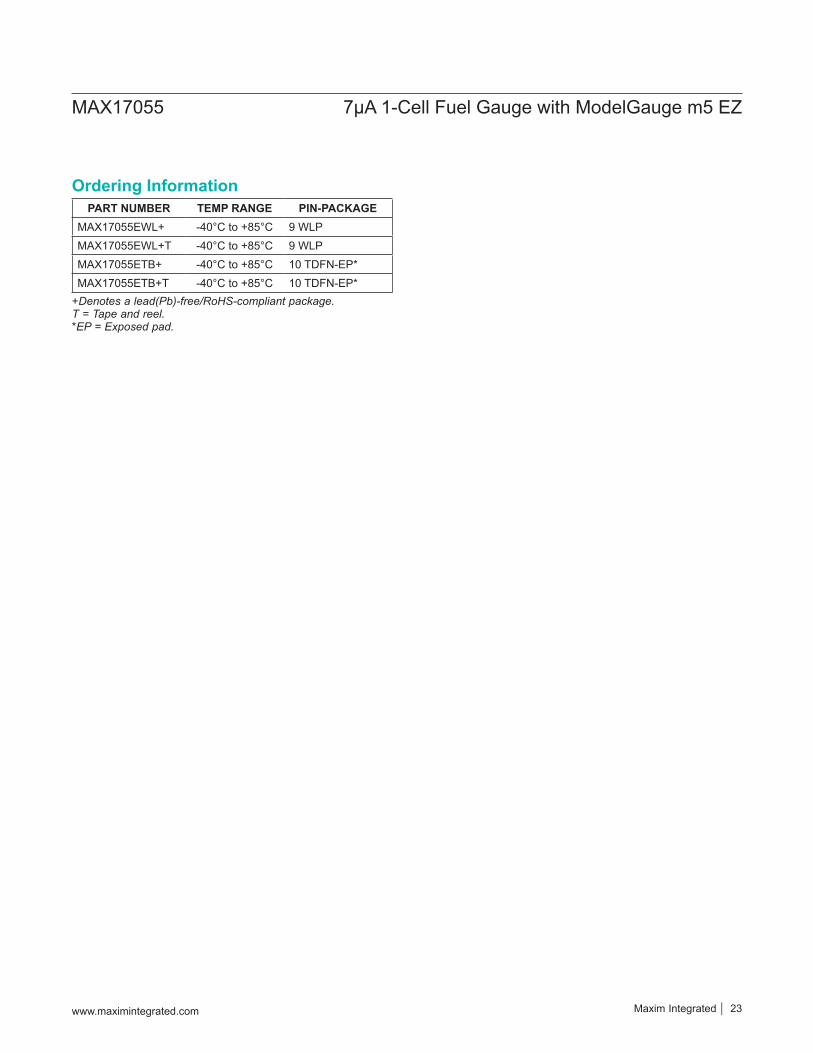
PART NUMBER TEMP RANGE PIN-PACKAGEMAX17055EWL+ -40°C to +85°C 9 WLPMAX17055EWL+T -40°C to +85°C 9 WLPMAX17055ETB+ -40°C to +85°C 10 TDFN-EP*MAX17055ETB+T -40°C to +85°C 10 TDFN-EP*
+Denotes a lead(Pb)-free/RoHS-compliant package. T = Tape and reel. *EP = Exposed pad.
Ordering Information
www.maximintegrated.com Maxim Integrated 23
MAX17055 7μA 1-Cell Fuel Gauge with ModelGauge m5 EZ
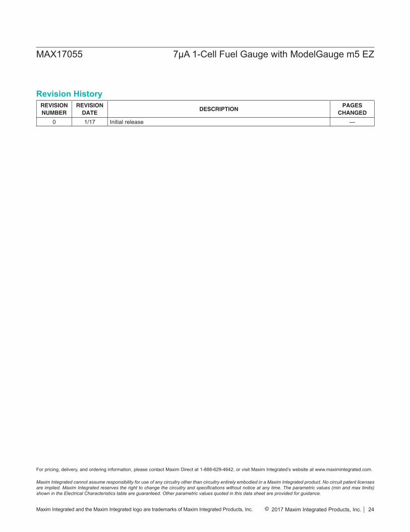
REVISIONNUMBER
REVISIONDATE
DESCRIPTIONPAGES
CHANGED
0 1/17 Initial release —
Revision History
Maxim Integrated cannot assume responsibility for use of any circuitry other than circuitry entirely embodied in a Maxim Integrated product. No circuit patent licenses are implied. Maxim Integrated reserves the right to change the circuitry and specifications without notice at any time. The parametric values (min and max limits) shown in the Electrical Characteristics table are guaranteed. Other parametric values quoted in this data sheet are provided for guidance.
Maxim Integrated and the Maxim Integrated logo are trademarks of Maxim Integrated Products, Inc. © 2017 Maxim Integrated Products, Inc. 24
MAX17055 7μA 1-Cell Fuel Gauge with ModelGauge m5 EZ
For pricing, delivery, and ordering information, please contact Maxim Direct at 1-888-629-4642, or visit Maxim Integrated’s website at www.maximintegrated.com.