Example 7 - node voltage.tuttle.merc.iastate.edu/ee201/topics/ac_analysis/ac...EE 201 AC analysis...
12
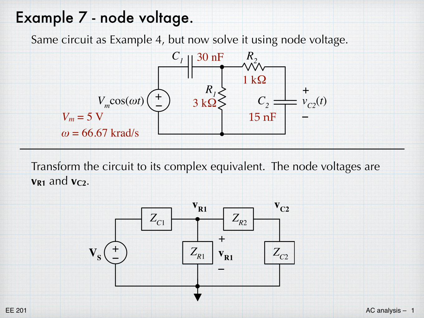
EE 201 AC analysis – 1 Example 7 - node voltage. Same circuit as Example 4, but now solve it using node voltage. + – V m cos(ωt) R 1 C 1 C 2 R 2 – + v C2 (t) 3 kΩ 15 nF 30 nF 1 kΩ V m = 5 V ω = 66.67 krad/s Transform the circuit to its complex equivalent. The node voltages are v R1 and v C2 . + – V S Z R1 Z C1 Z C2 Z R2 v C2 – + v R1 v R1
Transcript of Example 7 - node voltage.tuttle.merc.iastate.edu/ee201/topics/ac_analysis/ac...EE 201 AC analysis...
EE 201 AC analysis – �1
Example 7 - node voltage.Same circuit as Example 4, but now solve it using node voltage.
+–Vmcos(ωt)
R1
C1
C2
R2
–
+vC2(t)3 kΩ
15 nF
30 nF
1 kΩ
Vm = 5 Vω = 66.67 krad/s
Transform the circuit to its complex equivalent. The node voltages are vR1 and vC2.
+–VS ZR1
ZC1
ZC2
ZR2vC2
–
+vR1
vR1
EE 201 AC analysis – �2
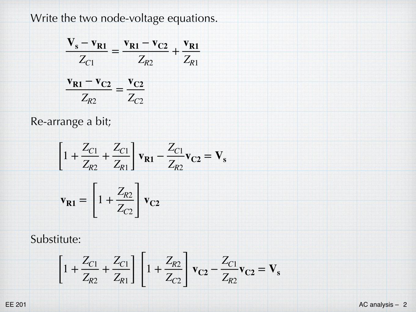
Write the two node-voltage equations.
Vs − vR1
ZC1=
vR1 − vC2
ZR2+
vR1
ZR1
vR1 − vC2
ZR2=
vC2
ZC2
Re-arrange a bit;
[1 +ZC1
ZR2+
ZC1
ZR1 ] vR1 −ZC1
ZR2vC2 = Vs
vR1 = [1 +ZR2
ZC2 ] vC2
[1 +ZC1
ZR2+
ZC1
ZR1 ] [1 +ZR2
ZC2 ] vC2 −ZC1
ZR2vC2 = Vs
Substitute:
EE 201 AC analysis – �3
[1 +1
jωR2C1+
1jωR1C1 ] [1 + jωR2C2] vC2 −
1jωR2C1
vC2 = Vs
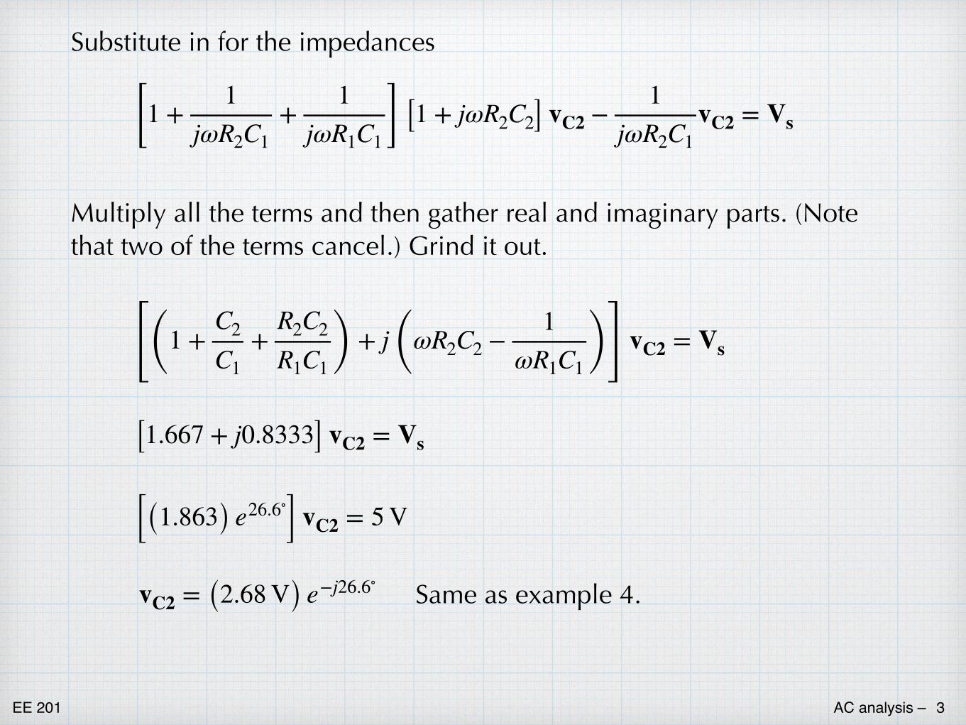
[(1 +C2
C1+
R2C2
R1C1 ) + j (ωR2C2 −1
ωR1C1 )] vC2 = Vs
[1.667 + j0.8333] vC2 = Vs
[(1.863) e26.6∘] vC2 = 5 V
vC2 = (2.68 V) e−j26.6∘
Substitute in for the impedances
Multiply all the terms and then gather real and imaginary parts. (Note that two of the terms cancel.) Grind it out.
Same as example 4.
EE 201 AC analysis – �4
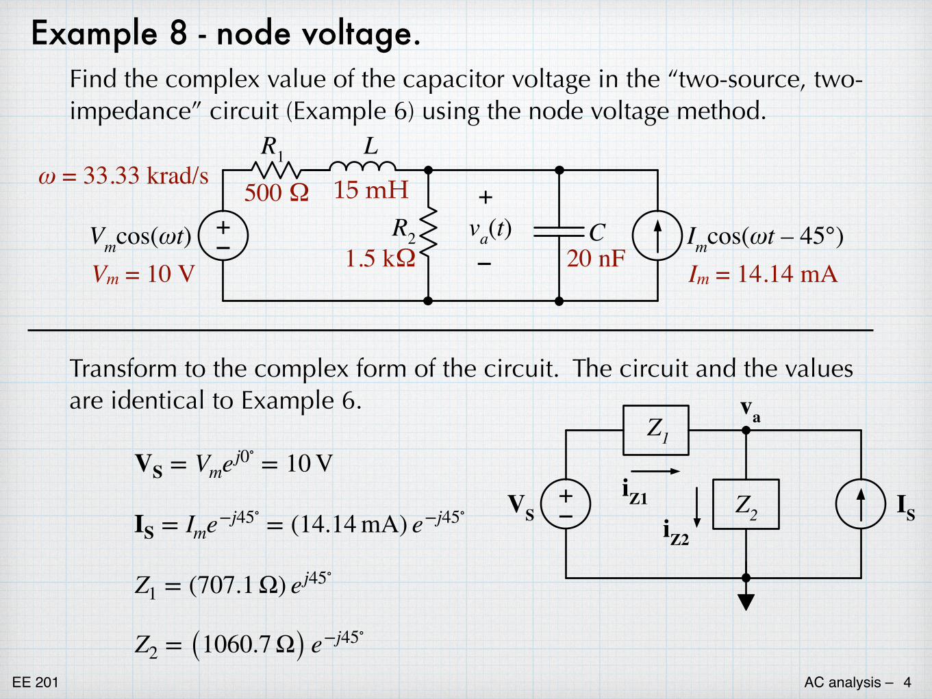
Example 8 - node voltage.Find the complex value of the capacitor voltage in the “two-source, two-impedance” circuit (Example 6) using the node voltage method.
VS = Vmej0∘ = 10 V
IS = Ime−j45∘ = (14.14 mA) e−j45∘
Z1 = (707.1 Ω) ej45∘
Z2 = (1060.7 Ω) e−j45∘
+–VS Z2
Z1
IS
va
iZ1
iZ2
Im = 14.14 mA
500 Ω 15 mH
1.5 kΩ 20 nFVm = 10 V
ω = 33.33 krad/s
+–Vmcos(ωt)
R1
R2
L
C Imcos(ωt – 45°)va(t)+
–
Transform to the complex form of the circuit. The circuit and the values are identical to Example 6.
EE 201 AC analysis – �5
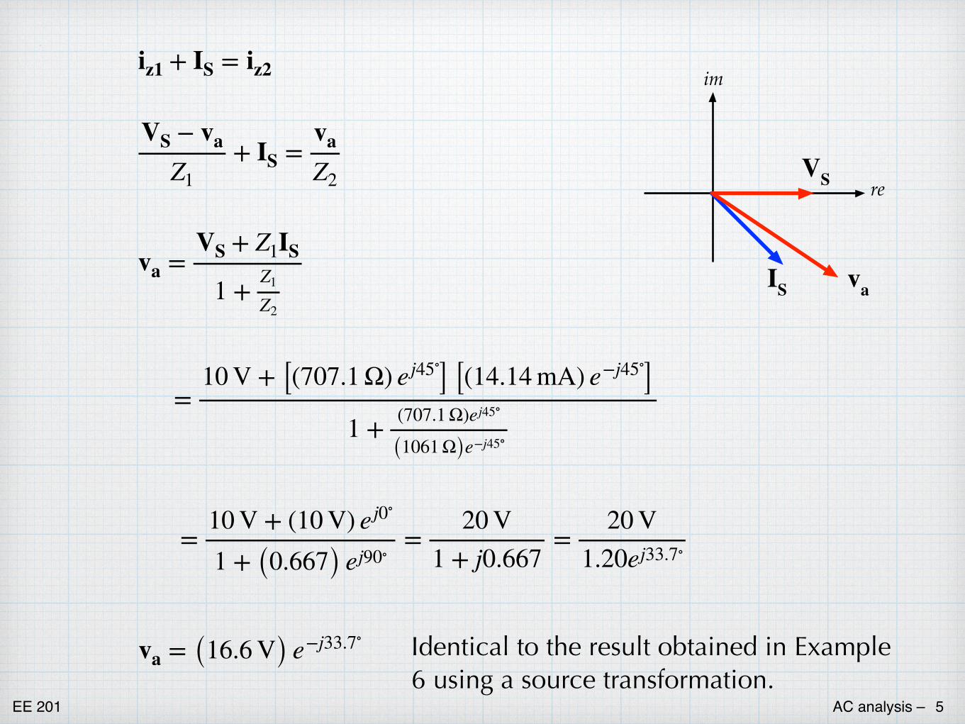
iz1 + IS = iz2
VS − va
Z1+ IS =
va
Z2
va =VS + Z1IS
1 + Z1
Z2
=10 V + [(707.1 Ω) ej45∘] [(14.14 mA) e−j45∘]
1 + (707.1 Ω)ej45∘
(1061 Ω)e−j45∘
=10 V + (10 V) ej0∘
1 + (0.667) ej90∘=
20 V1 + j0.667
=20 V
1.20ej33.7∘
va = (16.6 V) e−j33.7∘
im
reVS
IS va
Identical to the result obtained in Example 6 using a source transformation.
EE 201 AC analysis – �6
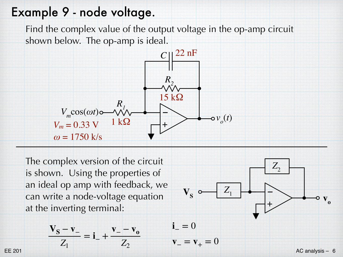
Example 9 - node voltage.Find the complex value of the output voltage in the op-amp circuit shown below. The op-amp is ideal.
1 kΩ
22 nF
Vm = 0.33 Vω = 1750 k/s
15 kΩ–+
R1
R2
C
Vmcos(ωt) vo(t)
–+
Z2
Z1VS vo
The complex version of the circuit is shown. Using the properties of an ideal op amp with feedback, we can write a node-voltage equation at the inverting terminal:
VS − v−
Z1= i− +
v− − vo
Z2
i− = 0v− = v+ = 0
EE 201 AC analysis – �7
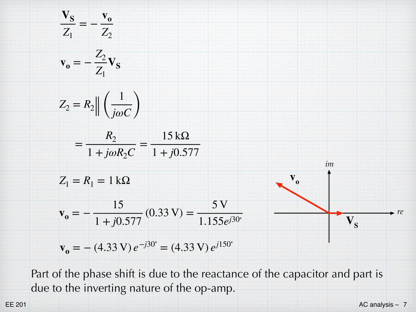
VS
Z1= −
vo
Z2
vo = −Z2
Z1VS
Z2 = R2 ( 1jωC )
=R2
1 + jωR2C=
15 kΩ1 + j0.577
Z1 = R1 = 1 kΩ
vo = −15
1 + j0.577(0.33 V) =
5 V1.155ej30∘
vo = − (4.33 V) e−j30∘ = (4.33 V) ej150∘
im
reVS
vo
Part of the phase shift is due to the reactance of the capacitor and part is due to the inverting nature of the op-amp.
EE 201 AC analysis – �8
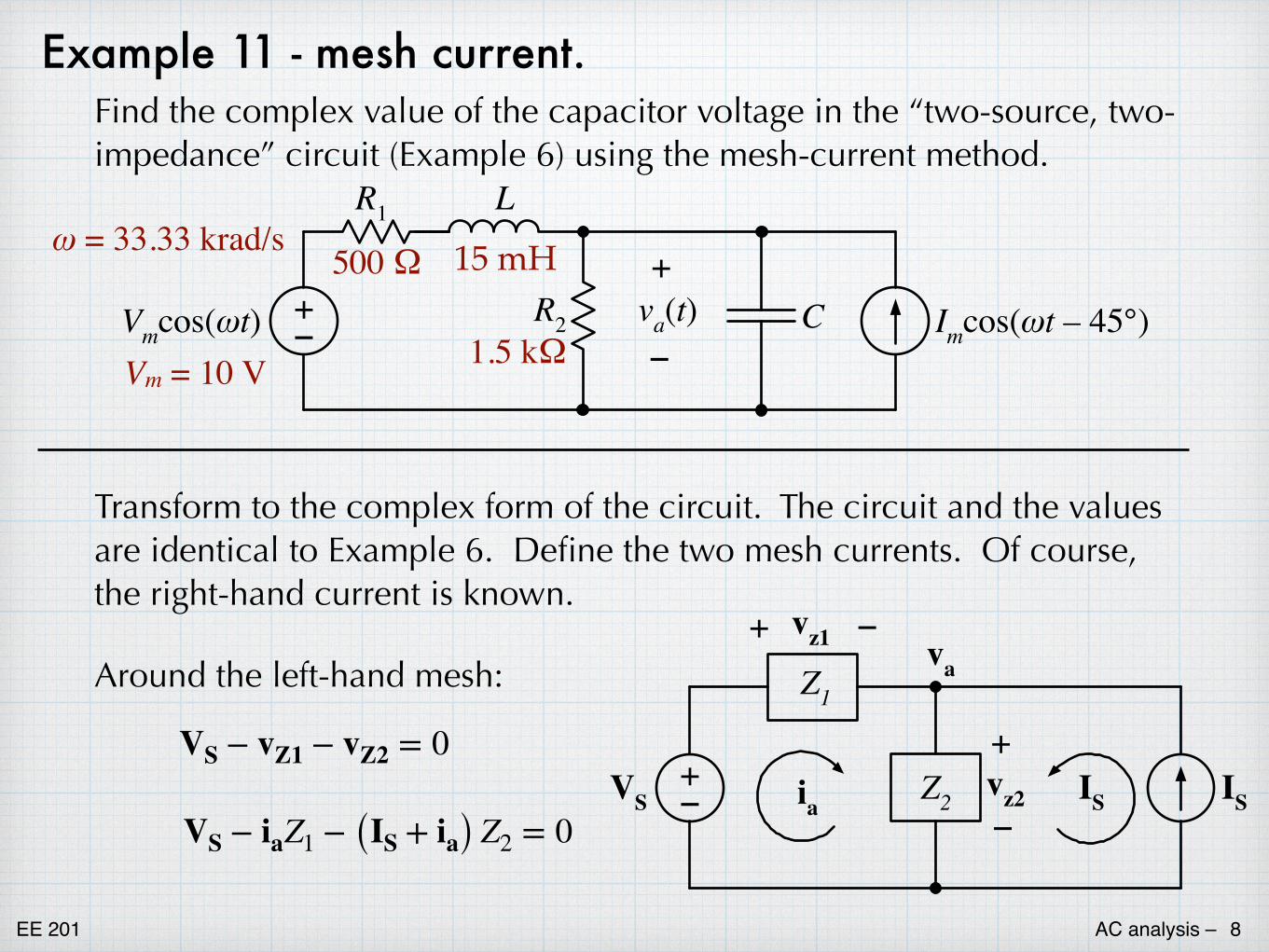
Example 11 - mesh current.Find the complex value of the capacitor voltage in the “two-source, two-impedance” circuit (Example 6) using the mesh-current method.
VS − iaZ1 − (IS + ia) Z2 = 0
VS − vZ1 − vZ2 = 0
500 Ω 15 mH
1.5 kΩVm = 10 V
ω = 33.33 krad/s
+–Vmcos(ωt)
R1
R2
L
C Imcos(ωt – 45°)va(t)+
–
Transform to the complex form of the circuit. The circuit and the values are identical to Example 6. Define the two mesh currents. Of course, the right-hand current is known.
Around the left-hand mesh:
+–VS Z2
Z1
IS
va
ia IS
vz1+ –
+
–vz2
EE 201 AC analysis – �9
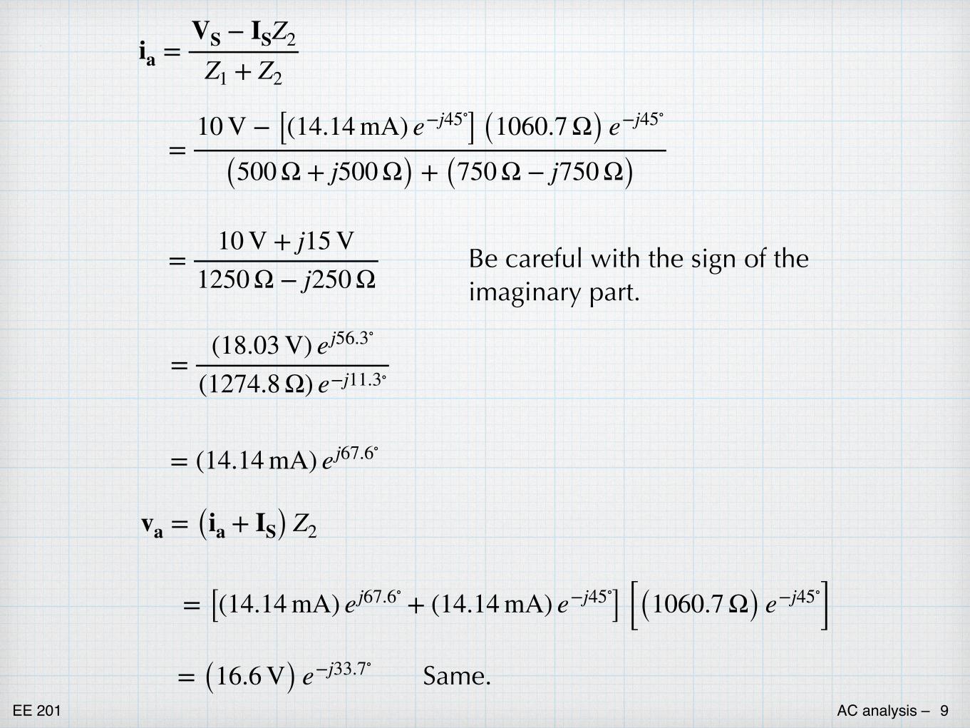
ia =VS − ISZ2
Z1 + Z2
=10 V − [(14.14 mA) e−j45∘] (1060.7 Ω) e−j45∘
(500 Ω + j500 Ω) + (750 Ω − j750 Ω)
=10 V + j15 V
1250 Ω − j250 Ω
= (14.14 mA) ej67.6∘
=(18.03 V) ej56.3∘
(1274.8 Ω) e−j11.3∘
va = (ia + IS) Z2
= [(14.14 mA) ej67.6∘ + (14.14 mA) e−j45∘] [(1060.7 Ω) e−j45∘]= (16.6 V) e−j33.7∘
Be careful with the sign of the imaginary part.
Same.
EE 201 AC analysis – �10
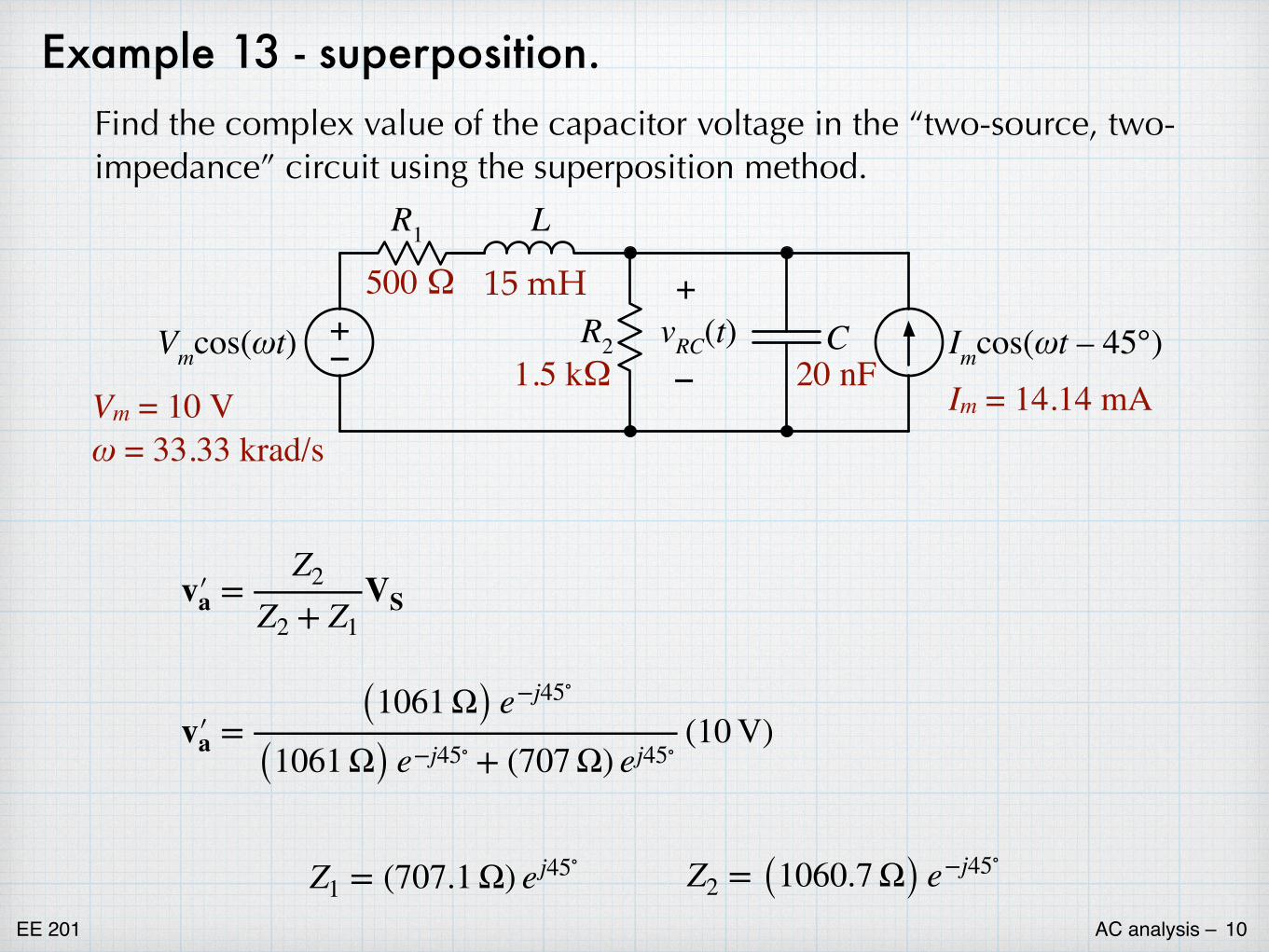
Example 13 - superposition.Find the complex value of the capacitor voltage in the “two-source, two-impedance” circuit using the superposition method.
+–Vmcos(ωt)
R1
R2
L
C Imcos(ωt – 45°)vRC(t)+
– Im = 14.14 mA
500 Ω 15 mH
1.5 kΩ 20 nFVm = 10 Vω = 33.33 krad/s
v′�a =Z2
Z2 + Z1VS
v′�a = (1061 Ω) e−j45∘
(1061 Ω) e−j45∘ + (707 Ω) ej45∘(10 V)
Z1 = (707.1 Ω) ej45∘ Z2 = (1060.7 Ω) e−j45∘
EE 201 AC analysis – �11
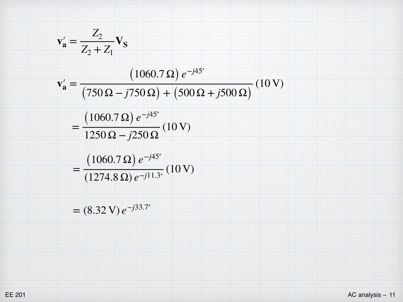
v′�a =Z2
Z2 + Z1VS
v′�a = (1060.7 Ω) e−j45∘
(750 Ω − j750 Ω) + (500 Ω + j500 Ω)(10 V)
= (1060.7 Ω) e−j45∘
1250 Ω − j250 Ω(10 V)
= (1060.7 Ω) e−j45∘
(1274.8 Ω) e−j11.3∘ (10 V)
= (8.32 V) e−j33.7∘
EE 201 AC analysis – �12
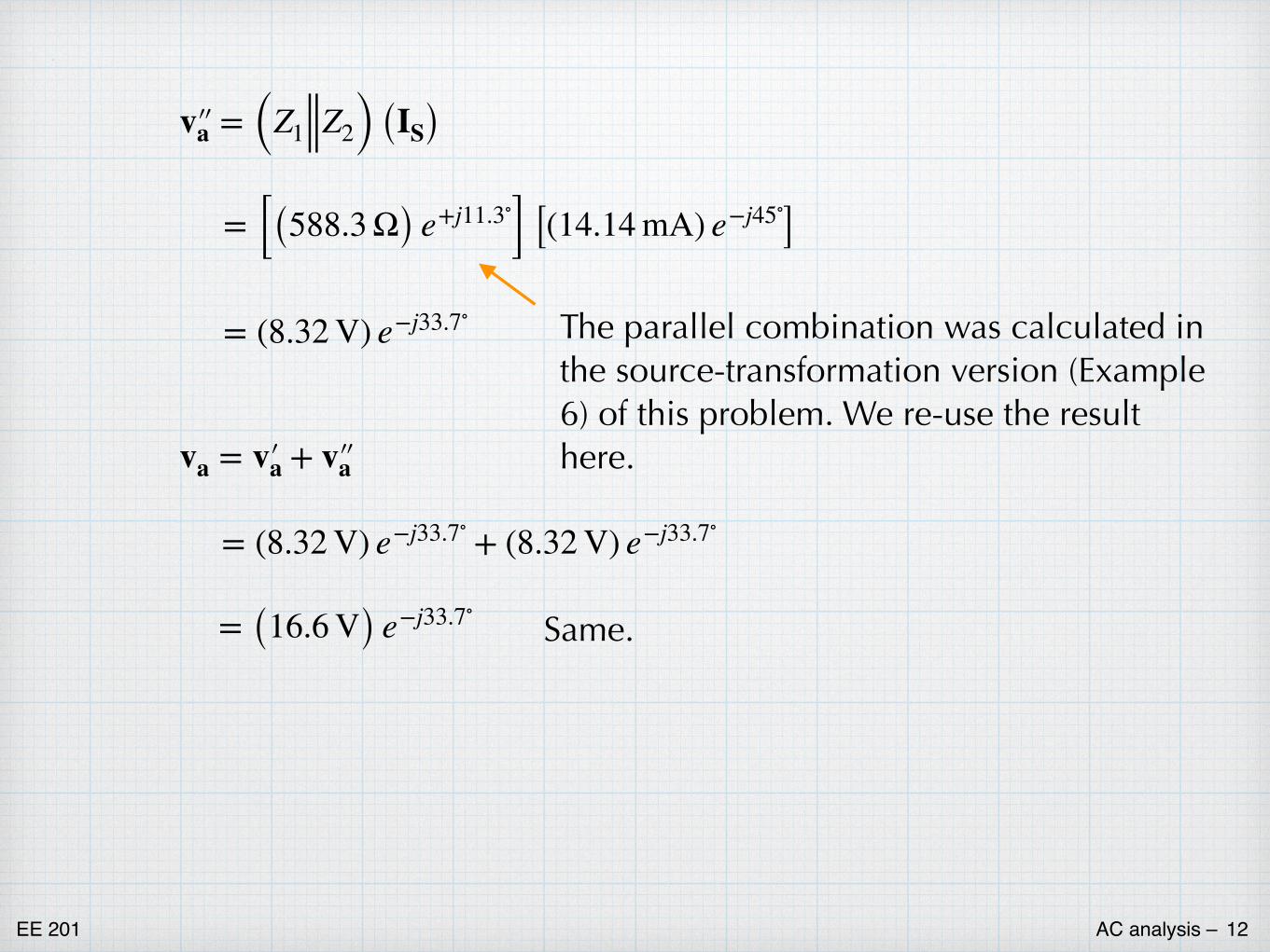
v′�′�a = (Z1 Z2) (IS)
= [(588.3 Ω) e+j11.3∘] [(14.14 mA) e−j45∘]
= (8.32 V) e−j33.7∘
va = v′�a + v′�′�a
= (8.32 V) e−j33.7∘ + (8.32 V) e−j33.7∘
= (16.6 V) e−j33.7∘Same.
The parallel combination was calculated in the source-transformation version (Example 6) of this problem. We re-use the result here.