
Euskal Herriko Unibertsitatea Universidad del País Vasco ...
65
KIMIKA FAKULTATEA FACULTAD DE QUÍMICA Euskal Herriko Unibertsitatea – Universidad del País Vasco Kimika Fakultatea – Facultad de Química Degree in Chemistry Final Year Project Development of a photosensitive organocatalyst for the ring-opening polymerization of ε-Caprolactone Author: Ander Gonzalez de Txabarri Director: Prof. Haritz Sardón Supervisor: Dr. Nicolas Zivic Donostia, June 2019
Transcript of Euskal Herriko Unibertsitatea Universidad del País Vasco ...
KIMIKA FAKULTATEA
FACULTAD DE QUÍMICA
Euskal Herriko Unibertsitatea – Universidad del País Vasco
Kimika Fakultatea – Facultad de Química
Degree in Chemistry
Final Year Project
Development of a photosensitive organocatalyst for the ring-opening
polymerization of ε-Caprolactone
Author: Ander Gonzalez de Txabarri
Director: Prof. Haritz Sardón
Supervisor: Dr. Nicolas Zivic
Donostia, June 2019
I
Summary
Biodegradable polyesters and polycarbonates are one of the main families of
biodegradable polymers and are widely synthesized by ring opening polymerization
(ROP) of lactones. An important field of use of these polyesters is the medical field,
where there is great interest in being able to fabricate 3D object like tissue scaffolds or
prostheses with these materials. Stereolithography or the 3D impression by controlled
photopolymerization is an area of fast development, but the range of available
monomers and photocatalysts is still very narrow. In the last years research on
organocatalysis for lactone ROP has been intense, with many organic acids catalysing
the cationic polymerization of these cyclic esters. The deactivation of these organic
acids to form photoacid generators, and the employability of these compounds for
stereolithography is a subject of great interest.
The goal of this project is to develop a photocatalyst able to catalyse a ROP
reaction with short reaction times. To find the best monomer, catalyst and conditions,
a screening work was done and several catalysts were tried in different conditions. The
fastest ones were selected to develop a photosensitive protocatalyst. This new
compounds were photoacid generators, an inactive catalyst with the ability to
decompose under UV light into the original organic acid. Finally, these photoacid
generators was tried to examine its behaviour under different conditions and its
catalytic power after decomposition.
II
Resumen
Los poliésteres y policarbonatos biodegradables son una de las principales
familias de polímeros biodegradables y biocompatibles, y son habitualmente
sintetizados por polimerización de apertura de anillo (ROP) de lactonas. Un ámbito
importante de uso de estos poliésteres es la medicina, donde hay un gran interés en la
posibilidad de fabricar objetos 3D como andamiajes para tejidos o prótesis. La
estereolitografía o la impresión 3D por fotopolimerización controlada es un área de
rápido desarrollo, pero el rango de monómeros y photocatalizadores disponibles es
muy estrecho todavía. En los últimos años la investigación en la organocatálisis de la
ROP de las lactonas ha sido muy intensa, con múltiples ácidos orgánicos catalizando la
polimerización catiónica de estos ésteres cíclicos. La desactivación de dichos ácidos
para formar fotogeneradores ácidos, y la empleabilidad de estos compuestos para la
estereolitografía es un campo de gran interés.
El objetivo de este proyecto es desarrollar un fotocatalizador capaz de catalizar
una reacción ROP con breves tiempos de reacción. Para encontrar el mejor monómero,
catalizador y condiciones se llevó a cabo un trabajo de screening y se probaron
múltiples catalizadores en distintas condiciones. Los catalizadores más rápidos fueron
escogidos para desarrollar protocatalizadores fotosensitivos. Los nuevos compuestos
eran fotogeneradores ácidos, unos catalizadores inactivos con la habilidad de
descomponerse bajo radiación ultravioleta y liberar el ácido original. Finalmente, se
estudió el comportamiento de los fotogeneradores ácidos bajo diferentes condiciones
y su potencial catalítico durante y tras la descomposición.
III
Index
1. Introduction 1
1.1. Objectives 4
1.2. Glossary and Abbreviations 5
1.3. Monomer Selection 6
1.4. Photoacid Generators 9
1.4.1. Iodonium Salts 11
1.4.2. Non Ionic Naphthalimide Based 13
1.4.3. Non Ionic Anthrone Based 15
2. Experimental Procedure 16
2.1. Materials 16
2.2. Model Reactions and Catalyst Screening 17
2.3. Photocatalyst Synthesis 22
2.3.1. Iodonium Salts 22
2.3.2. Non Ionic Naphthalimide Based 25
2.3.3. Non Ionic Anthrone Based 27
2.4. Photocatalyst Testing 28
2.4.1. Iodonium Salts 29
2.4.2. Non Ionic Naphthalimide Based 31
2.4.3. Non Ionic Anthrone Based 32
IV
3. Results And Discussion 34
3.1. Model Reactions and Catalyst Screening 34
3.2. Photocatalyst Synthesis 38
3.2.1. Iodonium Salts 39
3.2.2. Non Ionic Naphthalimide Based 44
3.2.3. Non Ionic Anthrone Based 47
3.3. Photolysis 49
3.4. Polymerization by Photocatalysts 52
4. Conclusions 55
5. Bibliography 59
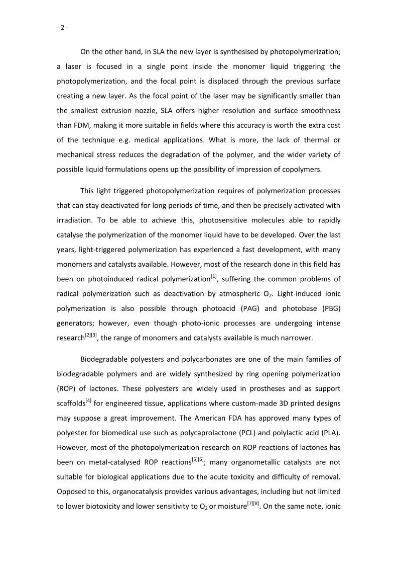
- 1 -
1.- Introduction
The technique of polymer 3D printing was born in the early 1980s, with the
invention of localized photo-curing of polymers and the 3D System Corporation patent
for an early stereolithography (SLA) system in 1984. In 1988 the company Stratasys
commercialized the first Fused Deposition Modelling (FDM) system, based on the
extrusion and deposition of molten polymer. During the 1990s the patents for FDM
processes expired and the technique was perfected; during this time other processes
like Selective Laser Melting (SLM) and Selective Laser Sintering (SLS) were developed.
These first systems were cumbersome, slow and expensive; the applications of this
early 3D printing were restricted to high-end objects like design models and rapid
prototyping. However, the new century came with an increase in miniaturization and
affordability of the machines, and desktop printers like the RepRap project in 2005 and
the Makerbot in 2009 and the foundation of the file library Thingiverse made of the 3D
printing systems a consumer product. Nowadays there is a very broad range of 3D
printing systems and applications, from inexpensive desktop printers to high-precision
industrial machines aimed at rapid prototyping and high added value objects like
prosthesis components.
There are several available processes for 3D printing, and although a
continuous curing technology was developed in 2014 by Carbon3D, all commercial
system work by the creation of a new layer of material over the previous layer to build
the object. The creation of the new layer may be by deposition of molten polymer (e.g.
FDM), the aggregation of smaller particles (e.g. SLM and SLS) or the synthesis of the
polymer by an external stimulus. The deposition of molten polymer is the simples of
the techniques, and as such is the easiest to execute and the cheapest. However, it
also comes with disadvantages: the range of polymers adequate for 3D printing is
increasing but is not very broad yet, the polymer chains may degrade due to the
thermal and mechanical stress of the extrusion, and the resolution of the technique is
limited by the practical nozzle size limits and the thermal expansion and contraction of
the polymers.
- 2 -
On the other hand, in SLA the new layer is synthesised by photopolymerization;
a laser is focused in a single point inside the monomer liquid triggering the
photopolymerization, and the focal point is displaced through the previous surface
creating a new layer. As the focal point of the laser may be significantly smaller than
the smallest extrusion nozzle, SLA offers higher resolution and surface smoothness
than FDM, making it more suitable in fields where this accuracy is worth the extra cost
of the technique e.g. medical applications. What is more, the lack of thermal or
mechanical stress reduces the degradation of the polymer, and the wider variety of
possible liquid formulations opens up the possibility of impression of copolymers.
This light triggered photopolymerization requires of polymerization processes
that can stay deactivated for long periods of time, and then be precisely activated with
irradiation. To be able to achieve this, photosensitive molecules able to rapidly
catalyse the polymerization of the monomer liquid have to be developed. Over the last
years, light-triggered polymerization has experienced a fast development, with many
monomers and catalysts available. However, most of the research done in this field has
been on photoinduced radical polymerization[1], suffering the common problems of
radical polymerization such as deactivation by atmospheric O2. Light-induced ionic
polymerization is also possible through photoacid (PAG) and photobase (PBG)
generators; however, even though photo-ionic processes are undergoing intense
research[2][3], the range of monomers and catalysts available is much narrower.
Biodegradable polyesters and polycarbonates are one of the main families of
biodegradable polymers and are widely synthesized by ring opening polymerization
(ROP) of lactones. These polyesters are widely used in prostheses and as support
scaffolds[4] for engineered tissue, applications where custom-made 3D printed designs
may suppose a great improvement. The American FDA has approved many types of
polyester for biomedical use such as polycaprolactone (PCL) and polylactic acid (PLA).
However, most of the photopolymerization research on ROP reactions of lactones has
been on metal-catalysed ROP reactions[5][6]; many organometallic catalysts are not
suitable for biological applications due to the acute toxicity and difficulty of removal.
Opposed to this, organocatalysis provides various advantages, including but not limited
to lower biotoxicity and lower sensitivity to O2 or moisture[7][8]. On the same note, ionic

- 3 -
catalysts are less sensitive to atmospheric conditions, and present lower toxicity than
their radical counterparts.
This project was carried out at the Innovative Polymers Group of the BERC-
POLYMAT, located at the Faculty of Chemistry of EHU/UPV in Donostia-San Sebastián,
Spain. The project was supervised by Dr. Nicolas Zivic and Prof. Haritz Sardón.
- 4 -
1.1.- Objectives
The objective of this project is to expand the library of monomers and catalysts
available for SLA 3D printing, focusing on lactones and carbonates polymerized by
organocatalyzed ROP.
First, based on previous research on polymerization by photosensitive
organocatalysts[7], a bibliographical study will be conducted to identify the reagents
and conditions under which the polymerization would be fast enough to be useful in
3D printing. This study will focus on ring opening cationic polymerization reactions
catalysed by organic acids.
Afterwards, an experimental study of the reaction speed under 3D printing
conditions will be carried out with different catalysts and molar ratios to determine the
optimal reagents and conditions.
Finally, a photocatalyst will be developed from the original organocatalyst and
its characteristics such as photosensitivity and catalytic power will be studied. The
objective for the photocatalyst is to obtain conversion values of >80% at 15 minutes of
reaction in bulk and at room temperature, with a maximum initiator and catalyst molar
ratio of 5%.
- 5 -
1.2.- Glossary and Abbreviations
Ε-CL: ε-Caprolactone monomer
MSA: Methanesulfonic Acid catalyst
TfOH: Triflic Acid, Trifluoromethanesulfonic Acid catalyst
TMC: Trimethylene carbonate monomer
PCL: Polycaprolactone polymer
PDM: p-Phenylene dimethanol initiator
TEA: Triethylamine base
- 6 -
Fig. 1. Structure of monomers ε-Caprolactone (ε-CL) and Trimethylene carbonate
(TMC), respectively.
1.3.- Monomer Selection
2 different monomers were studied: Trimethylene carbonate (TMC) and ε –
Caprolactone (ε-CL) (Fig.1); following a collaboration agreement, the group of Prof.
Andrew Dove would be studying L-Lactide. A review article published in 2015[6] proved
to be very useful as a summary of different catalysts and conditions for ROP of cyclic
esters and carbonates, as well as a gate to relevant literature. The goal of the study was
to find the theoretical conditions under which the ROP was fast (high conversions at <15
minutes) at bulk polymerization and with maximum 5% molar percentage of both
organic catalyst and initiator.
The major problem that was encountered during the literature review was the
lack of scientific papers describing the bulk ring-opening polymerization of polyesters.
Most (if not all) of the research described in the literature is about in solution
polymerization, with very low amounts of catalyst and very long reaction times
(between 8 and 72 hours, very long compared to the 15-30 minutes this project is
aiming for). Due to this lack of data, the literature review proved useful mostly for the
selection of the catalysts and monomers, but it was not useful for the stablishment of
the reaction conditions.
- 7 -
The first monomer to be studied was TMC. Poly(trimethylene carbonate) (PTMC)
is very useful as a homopolymer or copolymerized with L-Lactide and ε-CL in medical
applications. These polymers degrade in-vivo without releasing acidic byproducts[9],
making them ideal for temporal applications such as suture. However, the
polymerization described in the articles was very slow for our purposes. AS TMC is solid
at room temperature, instead of bulk polymerization the reaction is usually performed
in 1M solution. The polymerization times ranged from the very slow 22h (10% catalyst
molar percentage 1% initiator in CH2Cl2, r.t.)[10] and 6h (5% catalyst and initiator in
toluene, r.t.)[11] to the faster 45’ (15% catalyst molar percentage 2.5% initiator in
toluene, 30ºC)[12]. The usual catalysts were methanesulfonic acid (MSA), triflic acid
(TfOH) or diphenyl phosphate (DPP); the usual initiators were the monofunctional n-
penthanol or the bifunctional water and 1,4-phenylene dimethanol (PDM).
The second monomer to be studied was ε-CL. Polycaprolactone (PCL) is very used
as a biodegradable and biocompatible polymer as a homopolymer or copolymerized
with other polyesters. Again, almost all literature on PCL described in-solution
polymerization. The polymerization described in the literature is faster than the
reactions of TMC, ranging from 90’ (2.5% catalyst molar percentage and initiator in
toluene, 30ºC)[13] to 30’ (5% catalyst molar percentage and initiator in toluene, 30ºC)[13].
The most used catalysts were MSA and TfOH; Tf2NH was mentioned in a paper with long
reaction times, but very low catalyst ratio (0.2% catalyst molar percentage 2% initiator
in CH2Cl2)[14]. Again, the usual initiators were n-penthanol, water and PDM.
For this project, ε-CL was chosen as the appropriate monomer. The reaction
times described in the literature were longer than desired but not as long as the ones of
TMC and polymerization in bulk usually have shorter reaction times. For TMC, the
reaction times were too slow to be used in 3D printing and it was discarded as a viable
monomer for this project.
- 8 -
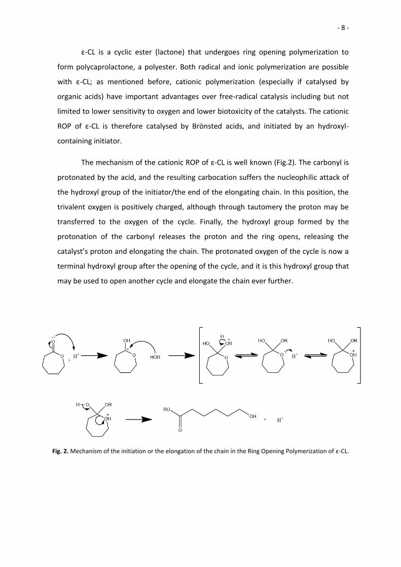
Fig. 2. Mechanism of the initiation or the elongation of the chain in the Ring Opening Polymerization of ε-CL.
ε-CL is a cyclic ester (lactone) that undergoes ring opening polymerization to
form polycaprolactone, a polyester. Both radical and ionic polymerization are possible
with ε-CL; as mentioned before, cationic polymerization (especially if catalysed by
organic acids) have important advantages over free-radical catalysis including but not
limited to lower sensitivity to oxygen and lower biotoxicity of the catalysts. The cationic
ROP of ε-CL is therefore catalysed by Brönsted acids, and initiated by an hydroxyl-
containing initiator.
The mechanism of the cationic ROP of ε-CL is well known (Fig.2). The carbonyl is
protonated by the acid, and the resulting carbocation suffers the nucleophilic attack of
the hydroxyl group of the initiator/the end of the elongating chain. In this position, the
trivalent oxygen is positively charged, although through tautomery the proton may be
transferred to the oxygen of the cycle. Finally, the hydroxyl group formed by the
protonation of the carbonyl releases the proton and the ring opens, releasing the
catalyst’s proton and elongating the chain. The protonated oxygen of the cycle is now a
terminal hydroxyl group after the opening of the cycle, and it is this hydroxyl group that
may be used to open another cycle and elongate the chain ever further.
- 9 -
1.4.- Photoacid Generators (PAG)
Photoacid generators are a subgroup of catalysts that are sensitive to irradiation.
These photosensitive molecules are able to generate an acid upon irradiation. Unlike
other triggers like heat, light can be applied with great spatial and temporal control and
in combination with PAGs allows for localized and controlled catalysis.
PAGs are usually sensitive to ultraviolet and/or visible light. Photons of that
wavelength contain enough energy to promote an electron from the ground state of the
molecule (HOMO) to a state with higher energy; this state is usually the first possible
excited state (LUMO)[15]. According to quantum mechanics, only photons with the same
energy as the energy gap between the two states is able to promote an electron; thus,
the molecule is able to absorb light of certain wavelengths (therefore, of certain energy)
and each molecule has a characteristic absorption spectra.
Molecules are generally not stable at this singlet excited state, and seek to relax
into a state of lower energy. This relaxation can happen through multiple different and
competing processes, including but not limited to internal conversion (releasing the
energy as heat), emission of electromagnetic radiation with or without intersystem
crossing to a triplet state (fluorescence and phosphorescence, respectively) or
decomposition of the triplet state (after the change of spin multiplicity from singlet to
triplet) through different processes such as electron transfer or proton transfer[15].
Photoacid generators are photosensitive compounds that, upon irradiation,
undergo a proton transfer process and yield an acid. As discussed previously, this acid
can be used as a catalyst to perform light-controlled cationic polymerizations.
Depending on the structure and the nature of the molecule, PAGs can be
classified in two major groups.
- 10 -
Ionic Photoacid Generators[7]
Ionic PAGs are composed of two or more ions that form a salt. These salts are
usually composed of a photosensitive cation, and the conjugated anion of an acid. Upon
irradiation, the cation decomposes into smaller molecules, releasing a proton in the
process. This proton is released alongside the conjugated anion to yield an acid. One of
the most common ionic PAG families is the iodonium photoacid family, with a
photosensitive cation containing a positive divalent iodine atom.
Due to their ionic nature, many of the ionic PAGs are hardly soluble in organic
solvents and monomers, limiting their usefulness to be employed as polymerization
catalysts.
Non-Ionic Photoacid Generators[7]
Non-ionic PAGs are neutral molecules that decompose into smaller molecules
upon irradiation, including a Brönsted or Lewis acid. In these molecules, the acid-to-be is
linked to the chromophore by an ester, sulfonic ester, phosphate ester… that is broken
upon irradiation. The resulting ion or radical (depending on the cleavage process) takes
a proton from another of the decomposition molecules or the solvent, forming an acid.
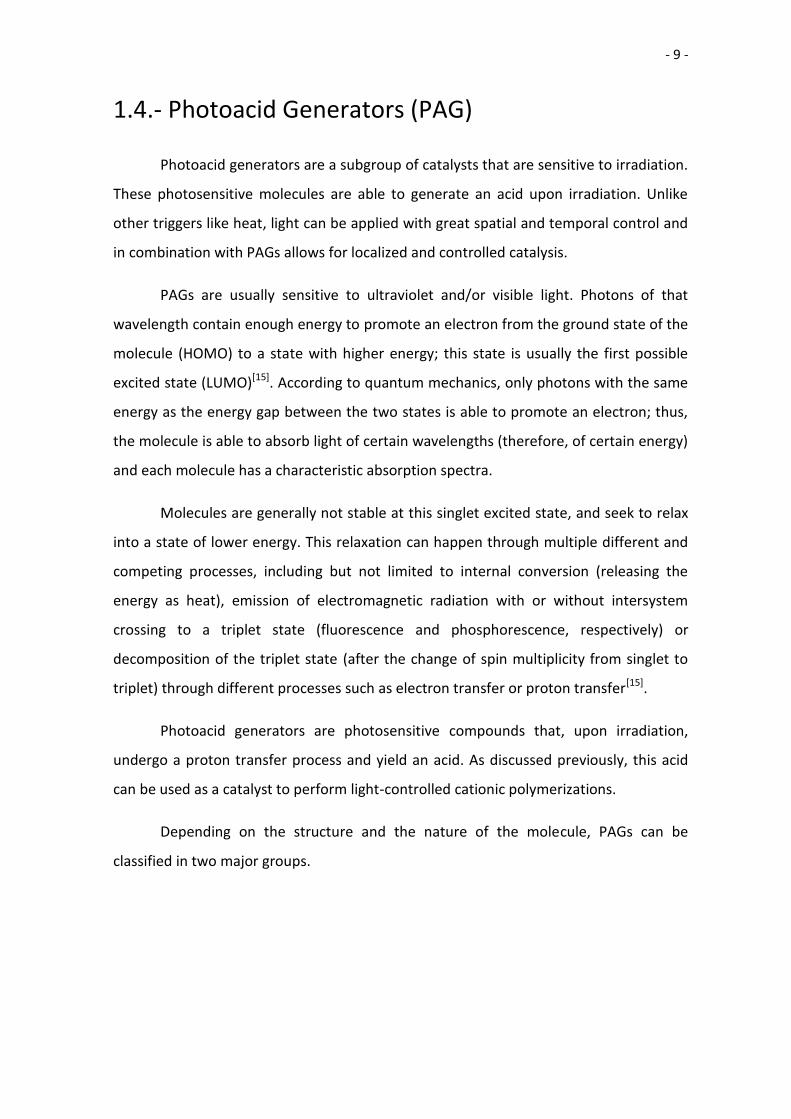
Based on the chromophore, the main families of non-ionic PAGs are the benzyl esters,
the imino esters and the conjugated imino esters (Fig. 3).
Fig. 3. Structure and decomposition of the main non-ionic PAG families[7]
- 11 -
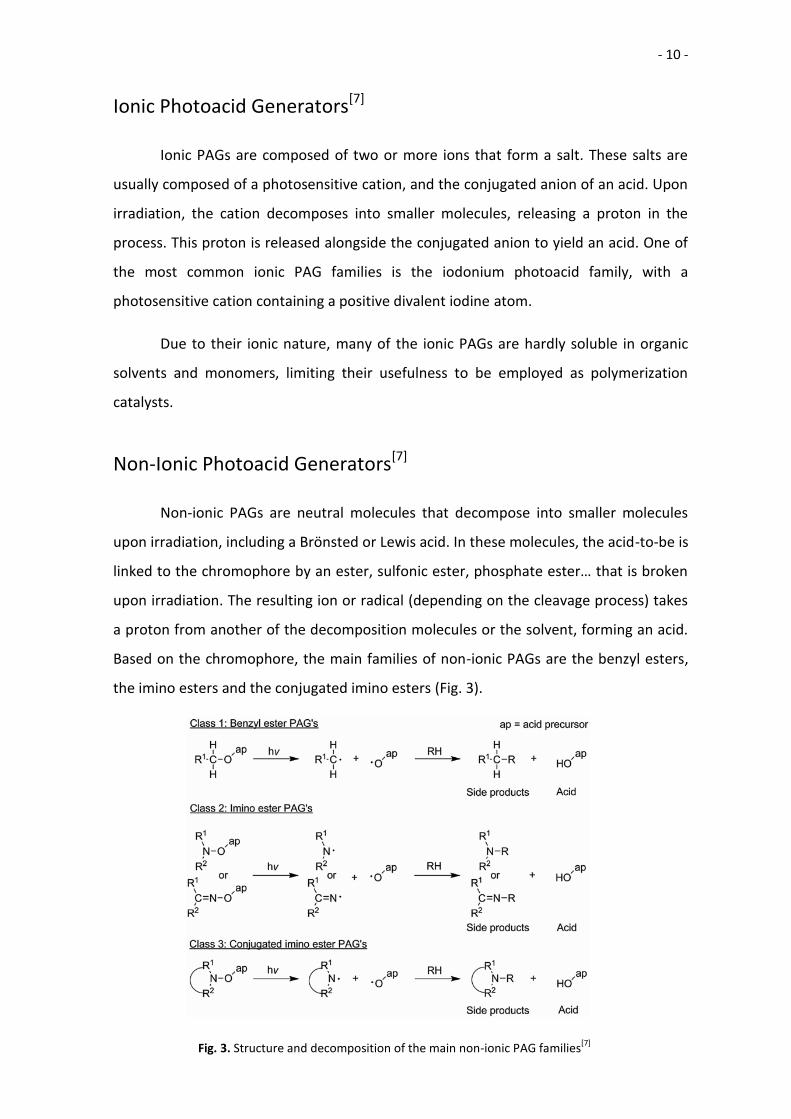
1.4.1.- Iodonium Salt Photocatalysts
Iodonium salts are a family of photoactive compounds that decompose under UV
light into neutral organic compounds and the protonated acid. The first use for cationic
polymerization of iodonium salts was described by Crivello in 1984[16].These salts consist
of a positively charged iodine atom bonded to 2 aromatic substituents. One of the
substituents is usually highly conjugated and able to absorb UV light, and when this
chromophore absorbs a photon the molecule transitions into an exited state. This
excited state is unstable and causes the decomposition of the molecule; the bond
between the iodine atom and the non-chromophore substituent suffers a homolytic
cleavage (Fig. 4)[17][18.a]. This process yields a phenyl radical and a cationic iodine radical.
Then the system can recombine back into the iodonium salt or it can undergo an
electron transfer process to link the phenyl radical and the chromophore; after this
linkage the system undergoes a proton transfer process, releasing the protonated acid
and a neutral organic molecule.
Fig. 4. Decomposition mechanism of Iodonium salts under UV light,
following the homolytic cleavage route described by Dektar et al.[17]
- 12 -
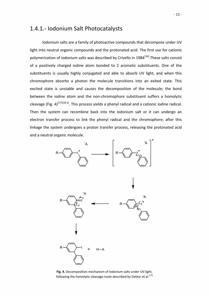
The Iodonium salts used in this project were based on naphthalimide, and
synthesized following the process described in the doctoral theses of Dr. Zivic[18.b].
Naphthalimide-based chromophores are used instead of simpler chromophores because
of their ability to absorb UV-A light, the least energetic wavelengths of the UV range; for
example, typical iodonium salts are only able to absorb irradiation with a wavelength
shorter that 300nm[17]. The best approach to the synthesis of these salts is by the
synthesis of the photosensitive cationic part first, and then the linkage with the
conjugated base of TfOH. After the salt with the trifluoromethanosulfonate is
synthesized, then the counteranion may be replaced by the counteranion of another
acid.
In our project, the “parent” catalyst developed was (4-(6-Bromo-1,3-dioxo-1H-
benzo[de]isoquinolin-2(3H)-yl)phenyl)(phenyl)iodonium trifluoromethanesulfonate; this
compound was named Iodonium-TfOH (Fig 5). Then, trifluoromethanesulfonate was
substituted by methanesulfonate, MSA’s counteranion, forming Iodonium-MSA.
Fig. 5. Naphthalimide based Iodonium Salts.
R= CF3 -> Iodonium-TfOH
R=CH3· -> Iodonium-MSA
- 13 -
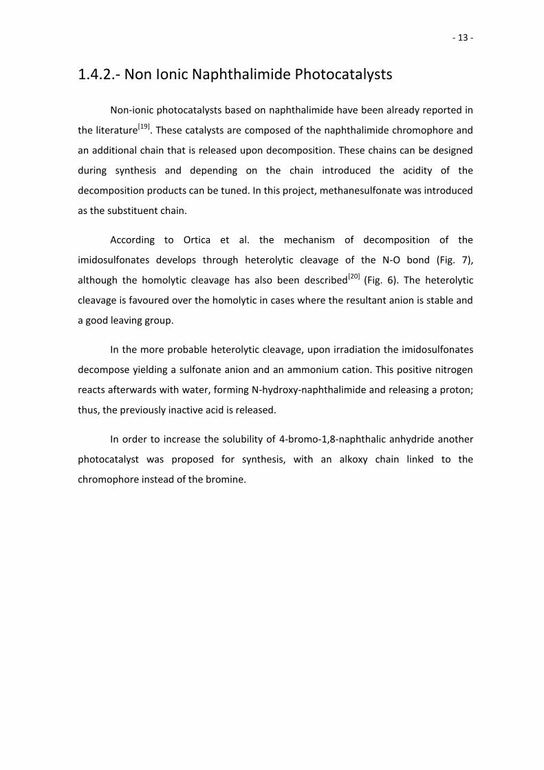
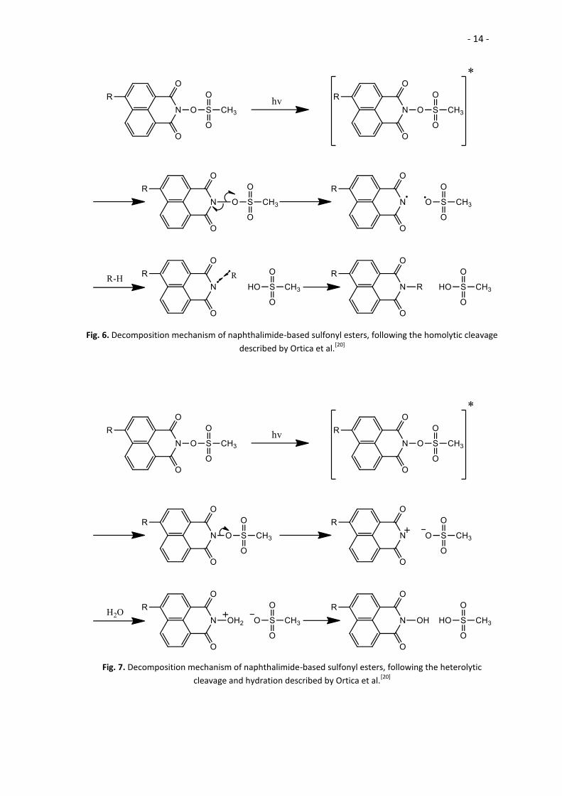
1.4.2.- Non Ionic Naphthalimide Photocatalysts
Non-ionic photocatalysts based on naphthalimide have been already reported in
the literature[19]. These catalysts are composed of the naphthalimide chromophore and
an additional chain that is released upon decomposition. These chains can be designed
during synthesis and depending on the chain introduced the acidity of the
decomposition products can be tuned. In this project, methanesulfonate was introduced
as the substituent chain.
According to Ortica et al. the mechanism of decomposition of the
imidosulfonates develops through heterolytic cleavage of the N-O bond (Fig. 7),
although the homolytic cleavage has also been described[20] (Fig. 6). The heterolytic
cleavage is favoured over the homolytic in cases where the resultant anion is stable and
a good leaving group.
In the more probable heterolytic cleavage, upon irradiation the imidosulfonates
decompose yielding a sulfonate anion and an ammonium cation. This positive nitrogen
reacts afterwards with water, forming N-hydroxy-naphthalimide and releasing a proton;
thus, the previously inactive acid is released.
In order to increase the solubility of 4-bromo-1,8-naphthalic anhydride another
photocatalyst was proposed for synthesis, with an alkoxy chain linked to the
chromophore instead of the bromine.
- 14 -
Fig. 6. Decomposition mechanism of naphthalimide-based sulfonyl esters, following the homolytic cleavage
described by Ortica et al.[20]
Fig. 7. Decomposition mechanism of naphthalimide-based sulfonyl esters, following the heterolytic
cleavage and hydration described by Ortica et al.[20]
- 15 -
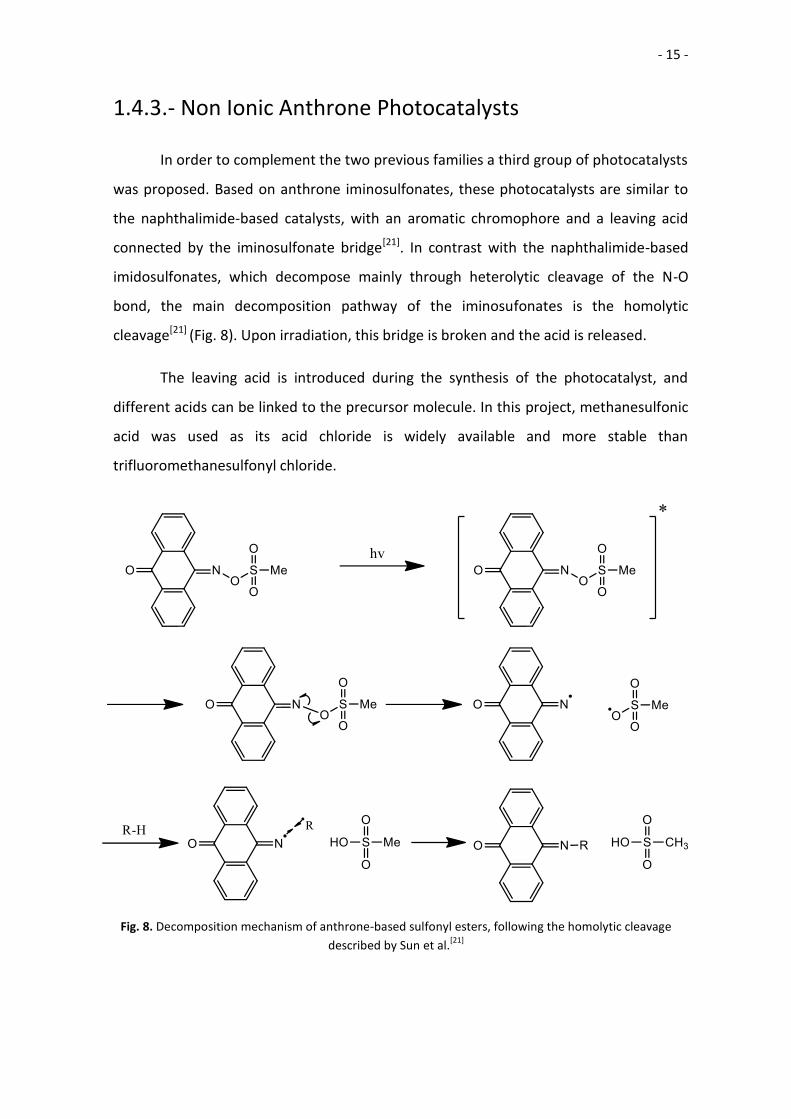
1.4.3.- Non Ionic Anthrone Photocatalysts
In order to complement the two previous families a third group of photocatalysts
was proposed. Based on anthrone iminosulfonates, these photocatalysts are similar to
the naphthalimide-based catalysts, with an aromatic chromophore and a leaving acid
connected by the iminosulfonate bridge[21]. In contrast with the naphthalimide-based
imidosulfonates, which decompose mainly through heterolytic cleavage of the N-O
bond, the main decomposition pathway of the iminosufonates is the homolytic
cleavage[21] (Fig. 8). Upon irradiation, this bridge is broken and the acid is released.
The leaving acid is introduced during the synthesis of the photocatalyst, and
different acids can be linked to the precursor molecule. In this project, methanesulfonic
acid was used as its acid chloride is widely available and more stable than
trifluoromethanesulfonyl chloride.
Fig. 8. Decomposition mechanism of anthrone-based sulfonyl esters, following the homolytic cleavage
described by Sun et al.[21]
- 16 -
2.- Experimental Procedure
2.1.- Materials Used
The monomer used was ε-Caprolactone (97%, bought at Sigma-Aldrich) CAS:
502-44-3. Its density is 1.07 g/mL. The molecular weight is 114.144 g/mol. It is a viscous,
pale yellow liquid.
The initiator used was p-phenylenedimethanol (>99%, bought at TCI) CAS: 589-
29-7. The molecular weight is 138.11 g/mol. It is a white solid.
The acid catalysts used were:
Methanesulfonic Acid (>99%, bought at Sigma-Aldrich) CAS: 75-75-2. The
molecular weight is 96.1 g/mol. Its density is 1.48 g/mL. It is a viscous, pale
yellow liquid.
Triflic Acid (98%, bought at Sigma-Aldrich). CAS: 1493-13-6. The molecular weight
is 150.08 g/mol. Its density is 1.696 g/mL. It is a fumant, viscous liquid.
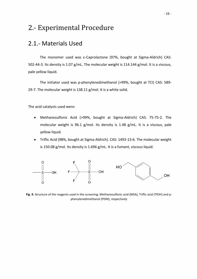
Fig. 9. Structure of the reagents used in the screening: Methanesulfonic acid (MSA), Triflic acid (TfOH) and p-
phenylenedimethanol (PDM), respectively
- 17 -
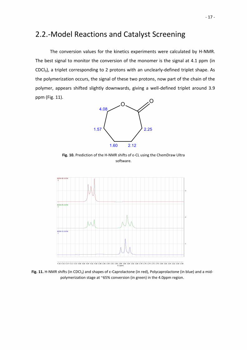
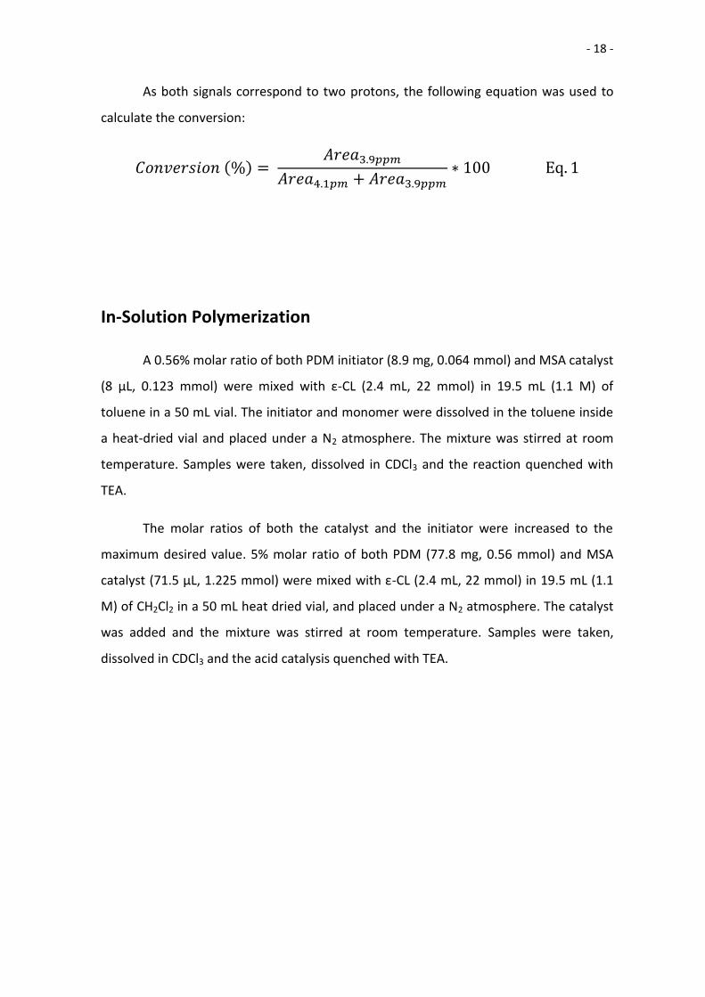
2.2.-Model Reactions and Catalyst Screening
The conversion values for the kinetics experiments were calculated by H-NMR.
The best signal to monitor the conversion of the monomer is the signal at 4.1 ppm (in
CDCl3), a triplet corresponding to 2 protons with an unclearly-defined triplet shape. As
the polymerization occurs, the signal of these two protons, now part of the chain of the
polymer, appears shifted slightly downwards, giving a well-defined triplet around 3.9
ppm (Fig. 11).
Fig. 10. Prediction of the H-NMR shifts of ε-CL using the ChemDraw Ultra
software.
Fig. 11. H-NMR shifts (in CDCl3) and shapes of ε-Caprolactone (in red), Polycaprolactone (in blue) and a mid-
polymerization stage at ~65% conversion (in green) in the 4.0ppm region.
- 18 -
As both signals correspond to two protons, the following equation was used to
calculate the conversion:
𝐶𝑜𝑛𝑣𝑒𝑟𝑠𝑖𝑜𝑛 (%) = 𝐴𝑟𝑒𝑎3.9𝑝𝑝𝑚
𝐴𝑟𝑒𝑎4.1𝑝𝑚 + 𝐴𝑟𝑒𝑎3.9𝑝𝑝𝑚∗ 100 Eq. 1
In-Solution Polymerization
A 0.56% molar ratio of both PDM initiator (8.9 mg, 0.064 mmol) and MSA catalyst
(8 μL, 0.123 mmol) were mixed with ε-CL (2.4 mL, 22 mmol) in 19.5 mL (1.1 M) of
toluene in a 50 mL vial. The initiator and monomer were dissolved in the toluene inside
a heat-dried vial and placed under a N2 atmosphere. The mixture was stirred at room
temperature. Samples were taken, dissolved in CDCl3 and the reaction quenched with
TEA.
The molar ratios of both the catalyst and the initiator were increased to the
maximum desired value. 5% molar ratio of both PDM (77.8 mg, 0.56 mmol) and MSA
catalyst (71.5 μL, 1.225 mmol) were mixed with ε-CL (2.4 mL, 22 mmol) in 19.5 mL (1.1
M) of CH2Cl2 in a 50 mL heat dried vial, and placed under a N2 atmosphere. The catalyst
was added and the mixture was stirred at room temperature. Samples were taken,
dissolved in CDCl3 and the acid catalysis quenched with TEA.
- 19 -
Bulk Polymerization – Ideal Conditions
ε-CL (2.4 mL, 22 mmol) was placed in a heat-dried 7 mL vial and the vial was
placed under a N2 atmosphere. Then, 5% molar percentage initiator (PDM 75.4 mg, 0.55
mmol) was added to the vial, and the mixture was stirred for 5’ to achieve a
homogeneous solution. Then, 5% of either catalyst (MSA: 71.5 μL, 1.225 mmol // TfOH:
99.5 μL, 1.125 mmol) was added, and the mixture was stirred at room temperature.
Samples of the mixture were taken until 15’ had passed; then, the samples were
dissolved in CDCl3 and the acid catalysis was quenched with TEA.
- 20 -
Bulk Polymerization – Open System
As mentioned before, the environment on which stereolithography is performed
is not as controlled as in the laboratory. In order to have a standard with which the
activity of the photocatalysts could be compared, bulk polymerization was also
performed in non-controlled conditions.
ε-CL (2.4 mL, 22 mmol) was placed in an undried 7 mL vial. Then, 5% molar
percentage initiator (PDM 75.4 mg, 0.55 mmol) was added to the vial, and the mixture
was stirred for 5’ to achieve a homogeneous solution. Then, 5% of either catalyst (MSA:
71.5 μL, 1.125 mmol // TfOH: 99.5 μL, 1.125 mmol) was added, and the mixture was
stirred at room temperature. Samples of the mixture were taken until 15’ had passed;
then, the samples were dissolved in CDCl3 and the acid catalysis was quenched with TEA.
Also, the experiment was repeated using 2.5% molar percentage of initiator and
catalyst. ε-CL (2.4 mL, 22 mmol) was placed in an undried 7 mL vial and 2.5% molar
percentage initiator (PDM 37.7 mg, 0.275 mmol) and 2.5% of either catalyst (MSA: 35.8
μL, 0.563 mmol // TfOH: 49.8 μL, 0.563 mmol) were added, and the mixture was stirred
at room temperature. Samples of the mixture were taken until 15’ had passed; then, the
samples were dissolved in CDCl3 and the acid catalysis was quenched with TEA.

- 21 -
Stability of Monomer-Initiator Pair
The final characteristic we were looking for in our system was the stability of the
mixture of the monomer and initiator; in order to be able to store the mixture, the
polymerization must not start before the addition of the catalyst. To check the stability
of the mixture ε-CL and 5% molar ratio of PDM were mixed in the vial, but no catalyst
was added. Then, the mixture was left stirring for 24h. As in the previous reactions,
samples were analysed by H-NMR.
- 22 -
2.3.- Synthesis of Photocatalysts
2.3.1.- Iodonium Salt Photocatalysts
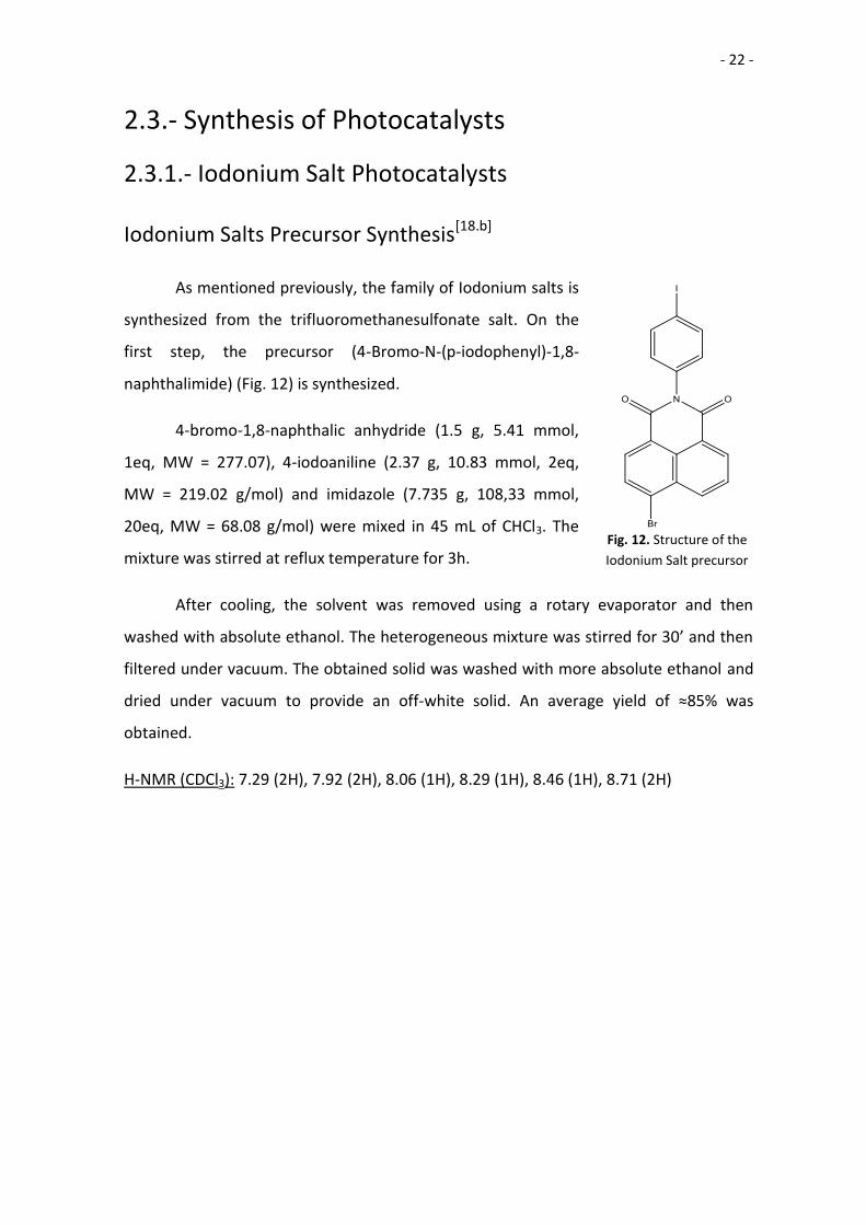
Iodonium Salts Precursor Synthesis[18.b]
As mentioned previously, the family of Iodonium salts is
synthesized from the trifluoromethanesulfonate salt. On the
first step, the precursor (4-Bromo-N-(p-iodophenyl)-1,8-
naphthalimide) (Fig. 12) is synthesized.
4-bromo-1,8-naphthalic anhydride (1.5 g, 5.41 mmol,
1eq, MW = 277.07), 4-iodoaniline (2.37 g, 10.83 mmol, 2eq,
MW = 219.02 g/mol) and imidazole (7.735 g, 108,33 mmol,
20eq, MW = 68.08 g/mol) were mixed in 45 mL of CHCl3. The
mixture was stirred at reflux temperature for 3h.
After cooling, the solvent was removed using a rotary evaporator and then
washed with absolute ethanol. The heterogeneous mixture was stirred for 30’ and then
filtered under vacuum. The obtained solid was washed with more absolute ethanol and
dried under vacuum to provide an off-white solid. An average yield of ≈85% was
obtained.
H-NMR (CDCl3): 7.29 (2H), 7.92 (2H), 8.06 (1H), 8.29 (1H), 8.46 (1H), 8.71 (2H)
Fig. 12. Structure of the
Iodonium Salt precursor
- 23 -
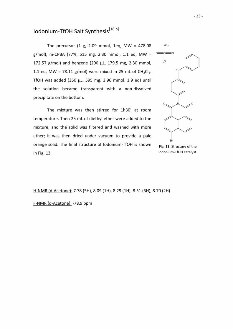
Iodonium-TfOH Salt Synthesis[18.b]
The precursor (1 g, 2.09 mmol, 1eq, MW = 478.08
g/mol), m-CPBA (77%, 515 mg, 2.30 mmol, 1.1 eq, MW =
172.57 g/mol) and benzene (200 μL, 179.5 mg, 2.30 mmol,
1.1 eq, MW = 78.11 g/mol) were mixed in 25 mL of CH2Cl2.
TfOH was added (350 μL, 595 mg, 3.96 mmol, 1.9 eq) until
the solution became transparent with a non-dissolved
precipitate on the bottom.
The mixture was then stirred for 1h30’ at room
temperature. Then 25 mL of diethyl ether were added to the
mixture, and the solid was filtered and washed with more
ether; it was then dried under vacuum to provide a pale
orange solid. The final structure of Iodonium-TfOH is shown
in Fig. 13.
H-NMR (d-Acetone): 7.78 (5H), 8.09 (1H), 8.29 (1H), 8.51 (5H), 8.70 (2H)
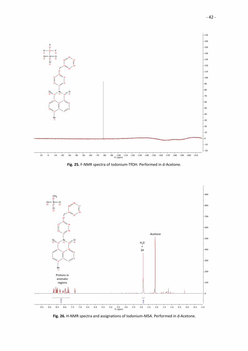
F-NMR (d-Acetone): -78.9 ppm
Fig. 13. Structure of the
Iodonium-TfOH catalyst.
- 24 -
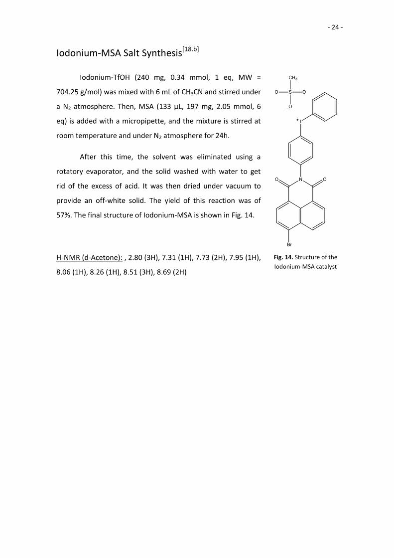
Iodonium-MSA Salt Synthesis[18.b]
Iodonium-TfOH (240 mg, 0.34 mmol, 1 eq, MW =
704.25 g/mol) was mixed with 6 mL of CH3CN and stirred under
a N2 atmosphere. Then, MSA (133 μL, 197 mg, 2.05 mmol, 6
eq) is added with a micropipette, and the mixture is stirred at
room temperature and under N2 atmosphere for 24h.
After this time, the solvent was eliminated using a
rotatory evaporator, and the solid washed with water to get
rid of the excess of acid. It was then dried under vacuum to
provide an off-white solid. The yield of this reaction was of
57%. The final structure of Iodonium-MSA is shown in Fig. 14.
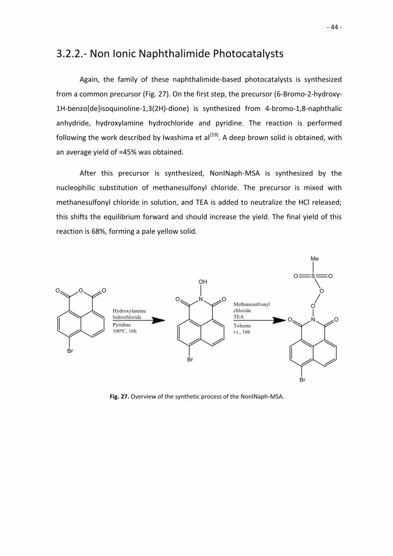
H-NMR (d-Acetone): , 2.80 (3H), 7.31 (1H), 7.73 (2H), 7.95 (1H),
8.06 (1H), 8.26 (1H), 8.51 (3H), 8.69 (2H)
Fig. 14. Structure of the
Iodonium-MSA catalyst
- 25 -
2.3.2.- Non Ionic Naphthalimide Photocatalysts
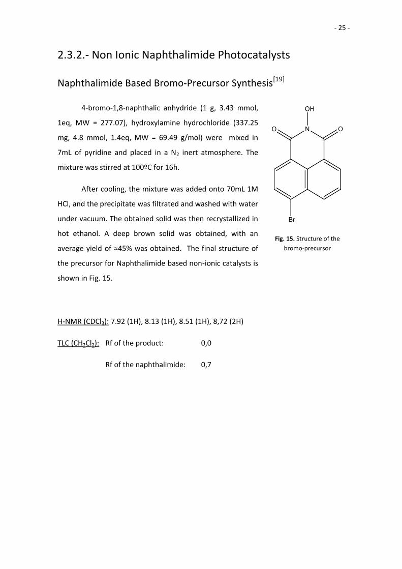
Naphthalimide Based Bromo-Precursor Synthesis[19]
4-bromo-1,8-naphthalic anhydride (1 g, 3.43 mmol,
1eq, MW = 277.07), hydroxylamine hydrochloride (337.25
mg, 4.8 mmol, 1.4eq, MW = 69.49 g/mol) were mixed in
7mL of pyridine and placed in a N2 inert atmosphere. The
mixture was stirred at 100ºC for 16h.
After cooling, the mixture was added onto 70mL 1M
HCl, and the precipitate was filtrated and washed with water
under vacuum. The obtained solid was then recrystallized in
hot ethanol. A deep brown solid was obtained, with an
average yield of ≈45% was obtained. The final structure of
the precursor for Naphthalimide based non-ionic catalysts is
shown in Fig. 15.
H-NMR (CDCl3): 7.92 (1H), 8.13 (1H), 8.51 (1H), 8,72 (2H)
TLC (CH2Cl2): Rf of the product: 0,0
Rf of the naphthalimide: 0,7
Fig. 15. Structure of the
bromo-precursor
- 26 -
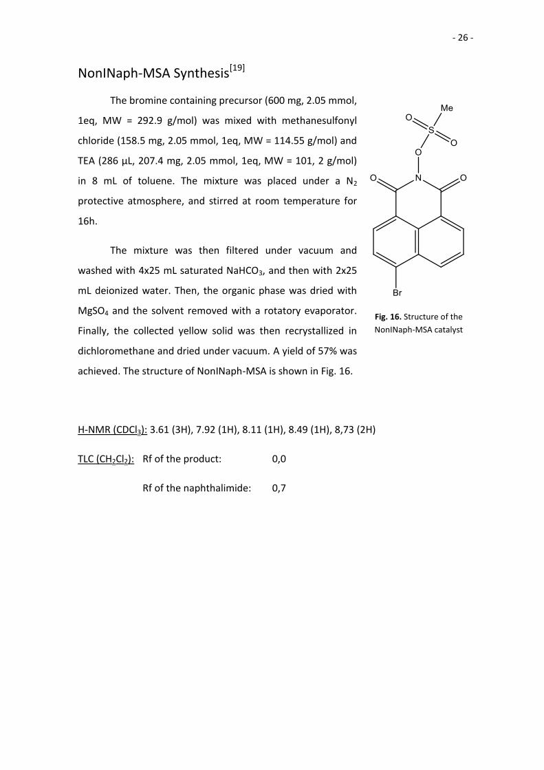
NonINaph-MSA Synthesis[19]
The bromine containing precursor (600 mg, 2.05 mmol,
1eq, MW = 292.9 g/mol) was mixed with methanesulfonyl
chloride (158.5 mg, 2.05 mmol, 1eq, MW = 114.55 g/mol) and
TEA (286 μL, 207.4 mg, 2.05 mmol, 1eq, MW = 101, 2 g/mol)
in 8 mL of toluene. The mixture was placed under a N2
protective atmosphere, and stirred at room temperature for
16h.
The mixture was then filtered under vacuum and
washed with 4x25 mL saturated NaHCO3, and then with 2x25
mL deionized water. Then, the organic phase was dried with
MgSO4 and the solvent removed with a rotatory evaporator.
Finally, the collected yellow solid was then recrystallized in
dichloromethane and dried under vacuum. A yield of 57% was
achieved. The structure of NonINaph-MSA is shown in Fig. 16.
H-NMR (CDCl3): 3.61 (3H), 7.92 (1H), 8.11 (1H), 8.49 (1H), 8,73 (2H)
TLC (CH2Cl2): Rf of the product: 0,0
Rf of the naphthalimide: 0,7
Fig. 16. Structure of the
NonINaph-MSA catalyst
- 27 -
2.3.3.- Non Ionic Anthrone Photocatalysts
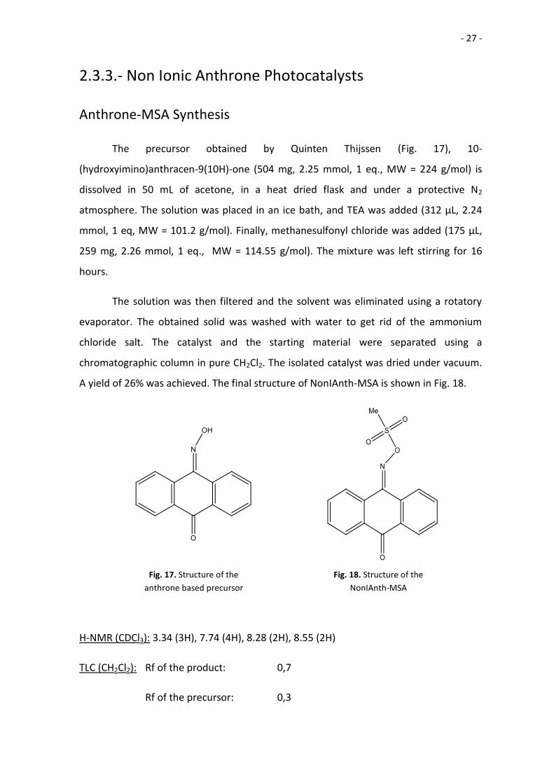
Anthrone-MSA Synthesis
The precursor obtained by Quinten Thijssen (Fig. 17), 10-
(hydroxyimino)anthracen-9(10H)-one (504 mg, 2.25 mmol, 1 eq., MW = 224 g/mol) is
dissolved in 50 mL of acetone, in a heat dried flask and under a protective N2
atmosphere. The solution was placed in an ice bath, and TEA was added (312 μL, 2.24
mmol, 1 eq, MW = 101.2 g/mol). Finally, methanesulfonyl chloride was added (175 μL,
259 mg, 2.26 mmol, 1 eq., MW = 114.55 g/mol). The mixture was left stirring for 16
hours.
The solution was then filtered and the solvent was eliminated using a rotatory
evaporator. The obtained solid was washed with water to get rid of the ammonium
chloride salt. The catalyst and the starting material were separated using a
chromatographic column in pure CH2Cl2. The isolated catalyst was dried under vacuum.
A yield of 26% was achieved. The final structure of NonIAnth-MSA is shown in Fig. 18.
H-NMR (CDCl3): 3.34 (3H), 7.74 (4H), 8.28 (2H), 8.55 (2H)
TLC (CH2Cl2): Rf of the product: 0,7
Rf of the precursor: 0,3
Fig. 18. Structure of the
NonIAnth-MSA
Fig. 17. Structure of the
anthrone based precursor
- 28 -
2.4.- Photocatalyst Testing
As the final step of the project, we wanted to measure the catalytic power of the
photocatalysts synthesized. In order to be able to compare the results with the ones
obtained with the pure acids, the same conditions of temperature, atmosphere and
molar ratios were employed.
The testing experiments consisted of two different phases with two different
goals:
First, the monomer-photocatalyst-initiator mixture was prepared and left stirring
for 24h. Samples were taken periodically to monitor the polymerization reaction.
The idea behind this experiment is to check if the mixture is stable and if it could
be prepared beforehand and stored prior to use.
The second part of the experiment tested the response of the mixture to UV
irradiation. The mixture was exposed to UV irradiation while stirring, and
samples were taken periodically to monitor the polymerization reaction.
The UV source used for these irradiation experiments was a LightingingCureTM
LC-L1V3 UV-LED light source. According to the manufacturer, the light source has an
output of 450 mW at 365 nm. The light source was placed at 10 cm over the mixture
surface.
- 29 -
2.4.1.- Iodonium Salt Photocatalysts
Stability and Irradiation with 2.5% Iodonium-TfOH
Iodonium-TfOH (102.4 mg, 0.1454 mmol, 5 eq, MW = 704.25 g/mol) was mixed in
a undried vial and not-inert atmosphere with PDM (11.0 mg, 0.0796 mmol, 2.5 eq) and
ε-CL (320 μL, 342.4 mg, 2.595 mmol, 100 eq). This 5% molar ratio mixture was not
homogeneous, and after stirring there were two separated phases with the catalyst
precipitated on the bottom of the vial. The same amount (320 μL, 342.4 mg, 2.595
mmol, 100 eq) of additional ε-CL was added, increasing the amount of monomer to 200
eq, and achieving a 2.5% molar ratio of catalyst and initiator.
This experiment was performed twice. In the first try, as the photocatalyst
proved to be non-soluble, the mixture was sonicated on ice to avoid thermal
degradation, but no solubilisation was obtained. The mixture was then dissolved in
acetone and then the solvent was eliminated using a rotatory evaporator. However,
during the evaporation the catalyst precipitated from the solution. What is more, the
amount of acetone needed to dissolve the amount of catalyst used was 4 or 5 times the
volume of the monomer. The mixture was left stirring at room temperature and non-
inert atmosphere for 24h, taking samples at 0, 1, 2, 4 and 24h.
In the second try, as there were concerns about the premature degradation that
these solubilisation methods may cause, the mixture was only stirred with a Vortex
machine to achieve a homogeneous suspension.
During this stability test, the sample was kept away from any UV source, covering
the vial with aluminium foil and keeping it inside the UV chamber. The conversion was
followed by H-NMR, using the same 4.2ppm and 4.0ppm signals (for ε-CL and PCL
respectively) used during the screening process; the samples were dissolved in CDCl3
and quenched with TEA.
- 30 -
After 24h, the sample was placed in a UV chamber. Due to the size of the vial,
the mixture was around 2 mm thick. The surface of the mixture was placed 10 cm away
from the lamp. The sample was irradiated by UV light, and samples were taken after 1,
2, 5, 10 and 15 minutes of irradiation. The samples were dissolved in CDCL3 and
quenched with TEA.
Another method was also tried in order to solubilize the catalyst. The catalyst
was dissolved in acetone, mixed with the monomer and initiator, and then the acetone
was eliminated using a rotatory evaporator. However, during the evaporation the
catalyst precipitated from the solution. What is more, the amount of acetone needed to
dissolve the amount of catalyst used was often 4 or 5 times the volume of the
monomer. Thus, it was decided that the sonication/vortex stirring method was the best
way to obtain a uniform distribution of catalyst in the sample.
- 31 -
2.4.2.- Non-Ionic Naphthalimide Photocatalysts
Stability and Irradiation with 2.5% NonINaph-MSA
NonINaph-MSA (100.4 mg, 0.2595 mmol, 2.5 eq, MW = 386.9 g/mol) was mixed
in a undried vial and not-inert atmosphere with PDM (18.2 mg, 0.132 mmol, 1.25 eq)
and ε-CL (1010 μL, 1081 mg, 9.47 mmol, 100 eq). This 2.5% molar ratio mixture was not
homogeneous as the catalyst was not soluble in the monomer, and the mixture was
shaken in a Vortex machine to obtain a uniform suspension.
The mixture was left stirring at room temperature and non-inert atmosphere for
24h, taking samples at 0, 1, 2, 4 and 24h. During this stability test the sample was kept
away from any UV source, covering the vial with aluminium foil and keeping in inside the
UV chamber. The samples were dissolved in CDCL3 and quenched with TEA. The
conversion was followed by H-NMR, using the same 4.2ppm and 4.0ppm signals (for ε-
CL and PCL respectively) used during the screening process.
After 24h, the sample was placed in a UV chamber. Due to the size of the vial,
the mixture was around 3 mm thick. The surface of the mixture was placed 10 cm away
from the lamp. The sample was irradiated by UV light, and samples were taken after 1,
2, 5, 10 and 15 minutes of irradiation. The samples were dissolved in CDCL3 and
quenched with TEA.
- 32 -
2.4.3.- Non-Ionic Anthrone Photocatalysts
Photolysis of 0.2M NonIAnth-MSA
NonIAnth-MSA (60.8 mg, 0.2026 mmol, MW = 300 g/mol) was dissolved in 1.0
mL of chloroform to make a solution with a concentration of catalyst similar to the used
in the polymerization experiments; this concentration of catalyst is around 0.2M (0.22
mmol in 1.01 mL of caprolactone).
The solution was placed 10 cm away from the UV light source. Samples were
taken after 10, 20, 40, 80, 160, 320, 640 and 1280 seconds, and put in vials in the dark to
evaporate the solvent. Then the solid samples were dissolved in CDCl3 and an H-NMR
analysis was performed.
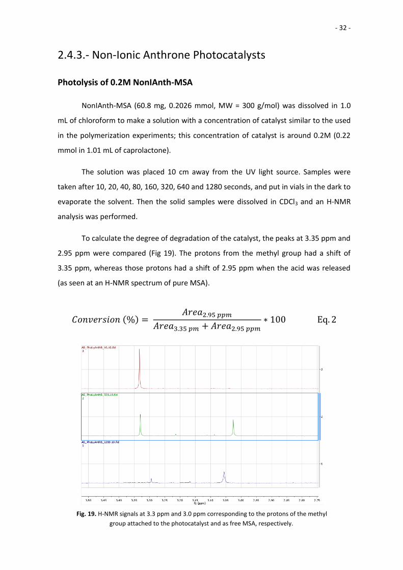
To calculate the degree of degradation of the catalyst, the peaks at 3.35 ppm and
2.95 ppm were compared (Fig 19). The protons from the methyl group had a shift of
3.35 ppm, whereas those protons had a shift of 2.95 ppm when the acid was released
(as seen at an H-NMR spectrum of pure MSA).
𝐶𝑜𝑛𝑣𝑒𝑟𝑠𝑖𝑜𝑛 (%) = 𝐴𝑟𝑒𝑎2.95 𝑝𝑝𝑚
𝐴𝑟𝑒𝑎3.35 𝑝𝑚 + 𝐴𝑟𝑒𝑎2.95 𝑝𝑝𝑚∗ 100 Eq. 2
Fig. 19. H-NMR signals at 3.3 ppm and 3.0 ppm corresponding to the protons of the methyl
group attached to the photocatalyst and as free MSA, respectively.
- 33 -
Photolysis of 0.01M NonIAnth-MSA
The same experiment was repeated but at much lower concentration. NonIAnth-
MSA (4.6 mg, 0.015 mmol, MW = 300 g/mol) was dissolved in 1.5 mL of chloroform to
make 1M solution.
The solution was placed 10 cm away from the UV light source. Samples were
taken after 10, 20, 40, 80, 160, 320, 640 and 1280 seconds, and put in vials in the dark to
evaporate the solvent. Then the solid samples were dissolved in CDCl3 and an H-NMR
analysis was performed. The percentage of acid released was measured the same way.
Stability and Irradiation with 2.5% NonIAnth-MSA
NonIAnth-MSA (75.8 mg mg, 0.253 mmol, 2.5 eq, MW = 300 g/mol) was mixed in
a undried vial and with a not-inert atmosphere with PDM (35.4 mg, 0.256 mmol, 2.5 eq)
and ε-CL (1078 μL, 1153 mg, 10.10 mmol, 100 eq). The catalyst was not soluble at first,
but after being shaken for 30” with a Vortex machine the catalyst dissolved in the
monomer.
The mixture was left stirring at room temperature and non-inert atmosphere for
24h, taking samples at 0, 1, 2, 4 and 24h. During this stability test the sample was kept
away from any UV source, covering the vial with aluminium foil and keeping in inside the
UV chamber. The samples were dissolved in CDCL3 and quenched with TEA. The
conversion was followed by H-NMR, using the same 4.2ppm and 4.0ppm signals (for ε-
CL and PCL respectively) used during the screening process.
After 24h, the sample was placed in a UV chamber. Due to the size of the vial,
the mixture was around 3 mm thick. The surface of the mixture was placed 10 cm away
from the lamp. The sample was irradiated by UV light, and samples were taken after 1,
2, 5, 10 and 15 minutes of irradiation. The samples were dissolved in CDCL3 and
quenched with TEA.
- 34 -
3.- Results and Discussion
3.1.- Model Reactions and Catalyst Screening
The reactions described in the literature are quite different from the conditions
on which 3D printing is carried out. Most articles describe in-solution polymerizations
with very long reaction times. Almost all of them carry out the ROP reactions under an
inert atmosphere. The goal of our project was the development a catalyst for bulk
polymerization with fast reaction times and flexible condition requirements; because of
that, the results described in the literature are useful as a starting point but are not valid
as a standard with which the results yielded by the photocatalyst experiments could be
compared.
These series of experiments would serve as model reactions for the ring opening
polymerization of model reactions for ε-CL, as well as to establish a framework with
which to compare the data obtained from the experiments with the photocatalysts.
First, we tried to replicate an in-solution reaction described in the literature. As the
results of the reaction were not successful, another in-solution reaction was designed
and carried out with better results.
Then, bulk polymerization was carried out using both MSA and TfOH as catalysts,
monitoring the conversion rate using H-NMR. The bulk-polymerization reactions were
performed using the maximum acceptable catalyst and initiator molar ratio, 5%. These
reactions were performed in controlled conditions of humidity and under an inert
atmosphere. However, in a 3D printing setup, the control the humidity and the reactivity
of the atmosphere are less controlled; under real conditions, the catalytic power of our
compounds could be different. In order to have a standard with which the activity of the
photocatalysts could be compared, bulk polymerization was also performed in non-
controlled conditions with 2 different catalyst and initiator molar ratios: 5% and 2.5%.
Finally, we wanted to check the stability of the monomer and initiator mixture
without the catalyst, to check if the combination used in our experiments was suitable
for storage.
- 35 -
In solution, polymerization was performed under the conditions described in the
literature[22]. We were not able to replicate the polymerization in solution described in
the literature[22] using only 0.56% of molar percentage of catalyst, as after 2h the
conversion values were still negligible. In the second reaction, with 5% of catalyst and
initiator molar percentage, the reaction speed was obviously faster than the speed
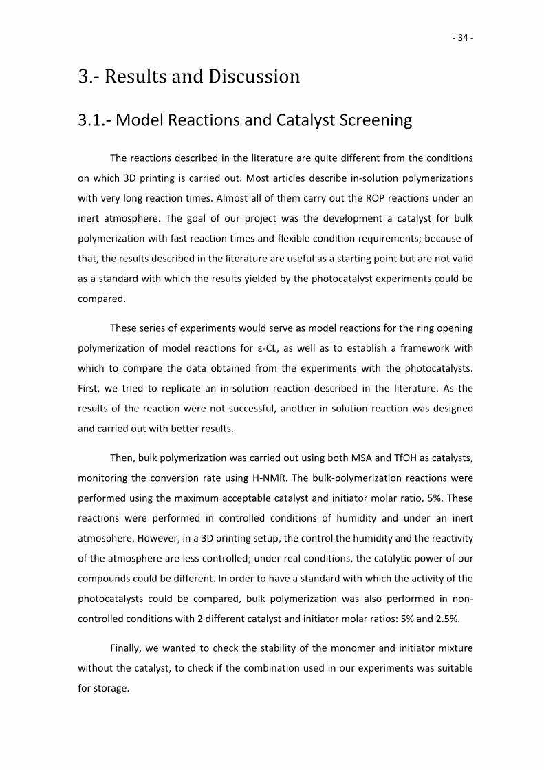
described in the paper, obtaining an 80% conversion at 30’ (Table 1).
We performed bulk polymerization of ε-CL with both of the catalysts described in
the literature: MSA and TfOH. First, the bulk polymerization was performed under ideal
conditions, under a N2 atmosphere and in a dry environment. Under these conditions,
the ROP would be faster than under use-conditions, but it would give us a value against
other results would be compared. The reactions for both catalysts were performed
following the same procedure and under the same conditions. In bulk, the ROP was
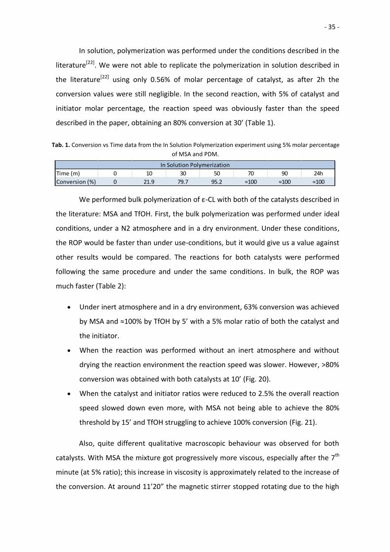
much faster (Table 2):
Under inert atmosphere and in a dry environment, 63% conversion was achieved
by MSA and ≈100% by TfOH by 5’ with a 5% molar ratio of both the catalyst and
the initiator.
When the reaction was performed without an inert atmosphere and without
drying the reaction environment the reaction speed was slower. However, >80%
conversion was obtained with both catalysts at 10’ (Fig. 20).
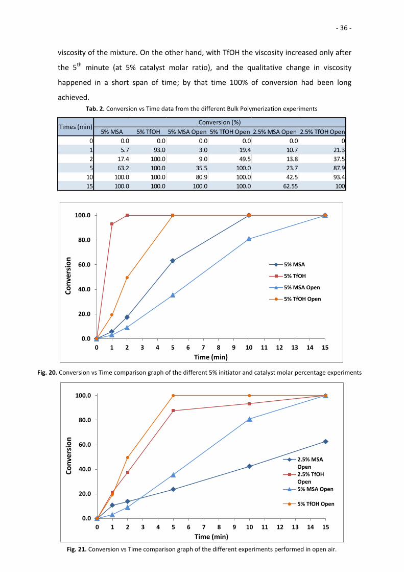
When the catalyst and initiator ratios were reduced to 2.5% the overall reaction
speed slowed down even more, with MSA not being able to achieve the 80%
threshold by 15’ and TfOH struggling to achieve 100% conversion (Fig. 21).
Also, quite different qualitative macroscopic behaviour was observed for both
catalysts. With MSA the mixture got progressively more viscous, especially after the 7th
minute (at 5% ratio); this increase in viscosity is approximately related to the increase of
the conversion. At around 11’20” the magnetic stirrer stopped rotating due to the high
Tab. 1. Conversion vs Time data from the In Solution Polymerization experiment using 5% molar percentage
of MSA and PDM.
Time (m) 0 10 30 50 70 90 24h
Conversion (%) 0 21.9 79.7 95.2 ≈100 ≈100 ≈100
In Solution Polymerization
- 36 -
Tab. 2. Conversion vs Time data from the different Bulk Polymerization experiments
5% MSA 5% TfOH 5% MSA Open 5% TfOH Open 2.5% MSA Open 2.5% TfOH Open
0 0.0 0.0 0.0 0.0 0.0 0
1 5.7 93.0 3.0 19.4 10.7 21.3
2 17.4 100.0 9.0 49.5 13.8 37.5
5 63.2 100.0 35.5 100.0 23.7 87.9
10 100.0 100.0 80.9 100.0 42.5 93.4
15 100.0 100.0 100.0 100.0 62.55 100
Times (min)Conversion (%)
viscosity of the mixture. On the other hand, with TfOH the viscosity increased only after
the 5th minute (at 5% catalyst molar ratio), and the qualitative change in viscosity
happened in a short span of time; by that time 100% of conversion had been long
achieved.
0.0
20.0
40.0
60.0
80.0
100.0
0 1 2 3 4 5 6 7 8 9 10 11 12 13 14 15
Co
nve
rsio
n
Time (min)
5% MSA
5% TfOH
5% MSA Open
5% TfOH Open
Fig. 20. Conversion vs Time comparison graph of the different 5% initiator and catalyst molar percentage experiments
0.0
20.0
40.0
60.0
80.0
100.0
0 1 2 3 4 5 6 7 8 9 10 11 12 13 14 15
Co
nve
rsio
n
Time (min)
2.5% MSAOpen2.5% TfOHOpen5% MSA Open
5% TfOH Open
Fig. 21. Conversion vs Time comparison graph of the different experiments performed in open air.
- 37 -
According to these results, it is clear that TfOH is strongly more active than MSA
when catalysing the ROP of ε-CL; it could easily be related to the difference between the
pKa of both acids (-14.7 of TfOH against the -1.9 of MSA). However, in the literature it
has been reported that the relationship between the pKa of an acid and its catalytic
activity is not clearly related[13], and that the activity of the catalysts is probably related
to the catalyst: initiator ratio. According to Gazeau-Bureau et al., the optimal ratio for
TfOH would be the 1:1 ratio used during our experiments, and MSA could be more
active when the ratio is favourable to the initiator. This would be caused by the
excessive acidity of TfOH, causing competitive protonation of the initiator as well as the
monomer. However, the exploration of multiple monomer/catalyst/initiator ratios and
their behaviour with both catalysts is beyond the scope of this project.
The difference between inert atmosphere/open air was the same for MSA and
TfOH; both reactions were slower under air. TfOH is known to be hygroscopic and more
sensitive to water than MSA, but no significant differences were found on the behaviour
of MSA and TfOH.
However, high conversion values were obtained with the 2.5% molar ratio at the
first few minutes. With both TfOH and MSA the conversion values were higher using a
2.5% molar ratio of catalyst and initiator than when 5% ratios were used. This
phenomenon could be related to the experimental results obtained by Gazeau-Bureau
et al. The low concentration of acid and initiator could speed up the reaction in the
beginning. After 2 minutes, in the 5% ratio experiments the higher amount of catalyst
and active chains (created because of a higher concentration of initiator) is enough to
overcome the initial lead and yield higher conversions.
Thus, both acid catalyst could be used for our project, as both catalysts are able
to obtain >80% conversion values at 15’ when a molar ratio of 5% is used. However, the
catalytic power of MSA is not strong enough to obtain the threshold of 80% conversion
when 2.5% molar ratio is used.
- 38 -
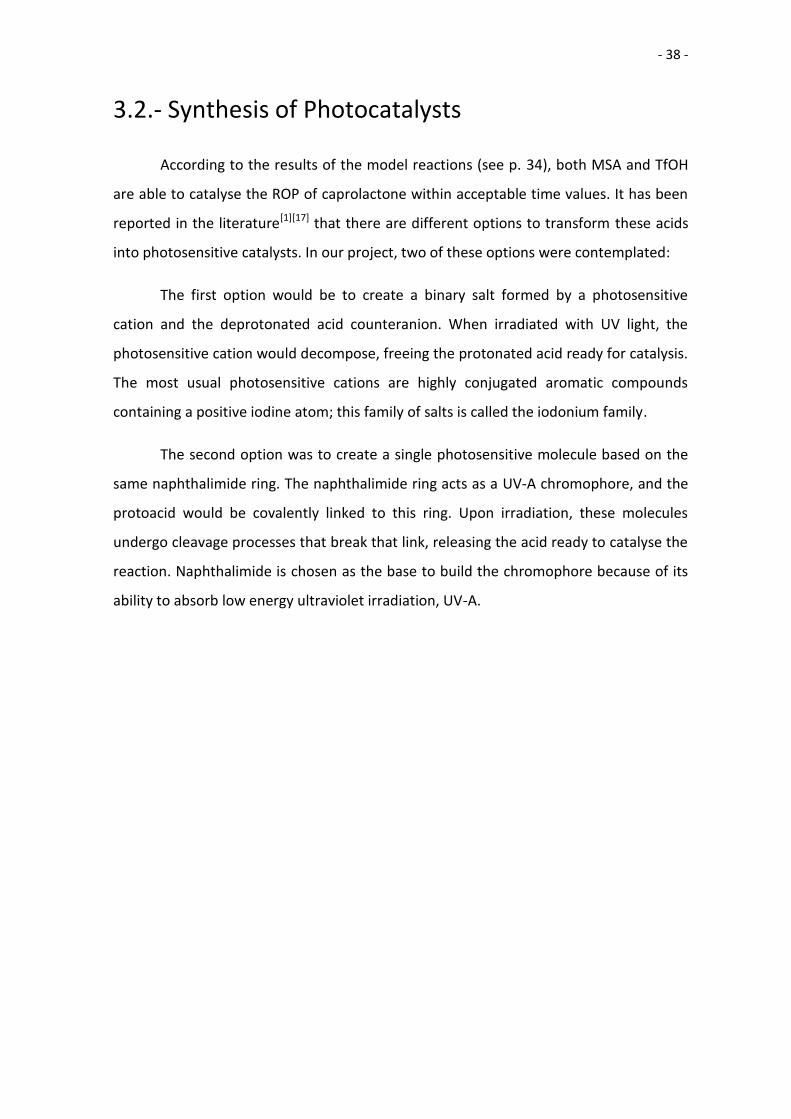
3.2.- Synthesis of Photocatalysts
According to the results of the model reactions (see p. 34), both MSA and TfOH
are able to catalyse the ROP of caprolactone within acceptable time values. It has been
reported in the literature[1][17] that there are different options to transform these acids
into photosensitive catalysts. In our project, two of these options were contemplated:
The first option would be to create a binary salt formed by a photosensitive
cation and the deprotonated acid counteranion. When irradiated with UV light, the
photosensitive cation would decompose, freeing the protonated acid ready for catalysis.
The most usual photosensitive cations are highly conjugated aromatic compounds
containing a positive iodine atom; this family of salts is called the iodonium family.
The second option was to create a single photosensitive molecule based on the
same naphthalimide ring. The naphthalimide ring acts as a UV-A chromophore, and the
protoacid would be covalently linked to this ring. Upon irradiation, these molecules
undergo cleavage processes that break that link, releasing the acid ready to catalyse the
reaction. Naphthalimide is chosen as the base to build the chromophore because of its
ability to absorb low energy ultraviolet irradiation, UV-A.
- 39 -
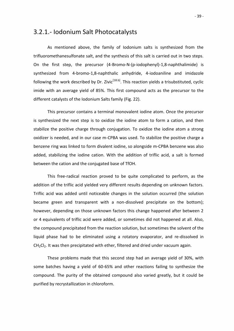
3.2.1.- Iodonium Salt Photocatalysts
As mentioned above, the family of Iodonium salts is synthesized from the
trifluoromethanesulfonate salt, and the synthesis of this salt is carried out in two steps.
On the first step, the precursor (4-Bromo-N-(p-iodophenyl)-1,8-naphthalimide) is
synthesized from 4-bromo-1,8-naphthalic anhydride, 4-iodoaniline and imidazole
following the work described by Dr. Zivic[18.b]. This reaction yields a trisubstituted, cyclic
imide with an average yield of 85%. This first compound acts as the precursor to the
different catalysts of the Iodonium Salts family (Fig. 22).
This precursor contains a terminal monovalent iodine atom. Once the precursor
is synthesized the next step is to oxidize the iodine atom to form a cation, and then
stabilize the positive charge through conjugation. To oxidize the iodine atom a strong
oxidizer is needed, and in our case m-CPBA was used. To stabilize the positive charge a
benzene ring was linked to form divalent iodine, so alongside m-CPBA benzene was also
added, stabilizing the iodine cation. With the addition of triflic acid, a salt is formed
between the cation and the conjugated base of TfOH.
This free-radical reaction proved to be quite complicated to perform, as the
addition of the triflic acid yielded very different results depending on unknown factors.
Triflic acid was added until noticeable changes in the solution occurred (the solution
became green and transparent with a non-dissolved precipitate on the bottom);
however, depending on those unknown factors this change happened after between 2
or 4 equivalents of triflic acid were added, or sometimes did not happened at all. Also,
the compound precipitated from the reaction solution, but sometimes the solvent of the
liquid phase had to be eliminated using a rotatory evaporator, and re-dissolved in
CH2Cl2. It was then precipitated with ether, filtered and dried under vacuum again.
These problems made that this second step had an average yield of 30%, with
some batches having a yield of 60-65% and other reactions failing to synthesize the
compound. The purity of the obtained compound also varied greatly, but it could be
purified by recrystallization in chloroform.
- 40 -
Iodonium-MSA is not synthesized following this route, but by anion substitution.
In order to change the anion of the salt, Iodonium-TfOH is dissolved and excess amounts
of MSA are added. This reaction was performed following the similar anion substitution
performed by Dr. Zivic[18.b], although the substitution described in his work used p-
toluensulfonic acid as the substituting anion. The reaction had a yield of 57%, but the
purity of the off-white solid obtained was not measured. The H-NMR spectrum shows
multiple peaks that could not be identified, and the F-NMR spectra showed
contamination by fluorine, indicating the presence of triflate anions. Recrystallization
proved futile, and no chromatographic column could be performed.
As this mixture of compounds was not soluble in ε-CL, the compound was
abandoned in favour of the exploration of non-ionic photocatalysts.
Fig. 22. Overview of the synthetic process of the Iodonium Salt family catalysts.
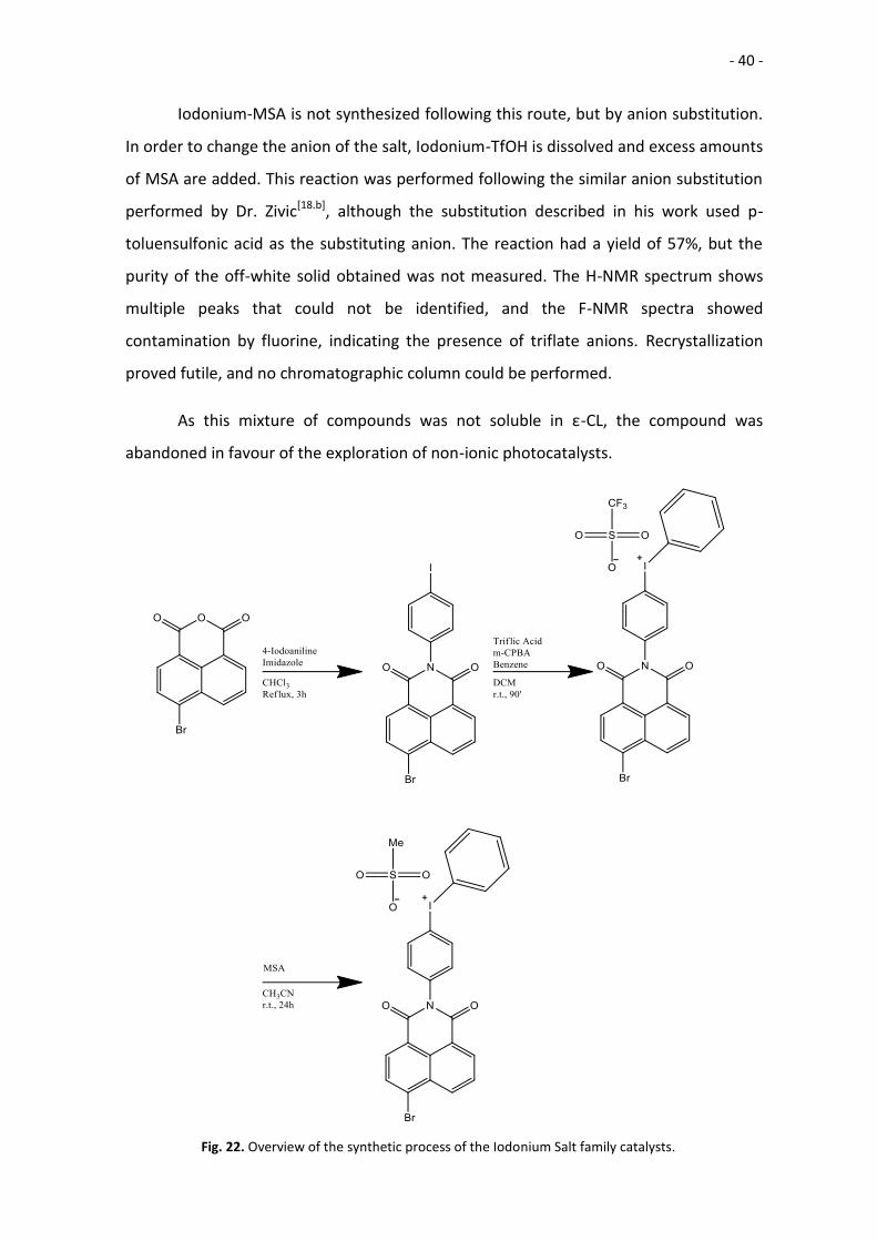
- 41 -
AcetoneH20
18 22
19 21
7, 9 4 5
8
Fig. 23. H-NMR spectra and assignations of the precursor for the Iodonium Salt family. Performed
in d-Acetone.
Acetone
H20
18, 2226, 27
28
8
5
7, 9
4, 1921, 25
29
Fig. 24. H-NMR spectra and assignations of Iodonium-TfOH. Performed in d-Acetone.
- 42 -
Fig. 25. F-NMR spectra of Iodonium-TfOH. Performed in d-Acetone.
Acetone
H20+
34
Protons inaromaticregions
Fig. 26. H-NMR spectra and assignations of Iodonium-MSA. Performed in d-Acetone.

- 43 -
Due to the contamination of the solid, there are too many signals in the aromatic
region of the H-NMR spectrum. The predictions of the spectra by MestReNova and
ChemDraw were not helpful, and no assignation could be done on those peaks. Also, the
signal for the methyl group of the methanesulfonate anion and the signal for the water
impurities on the solvent overlap, yielding an integral way over its true value and
creating the “belly” on the right of the peak.
- 44 -
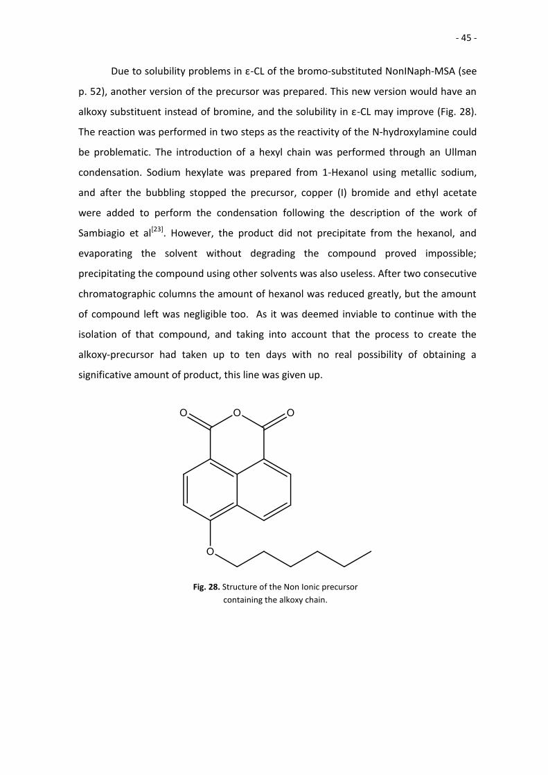
3.2.2.- Non Ionic Naphthalimide Photocatalysts
Again, the family of these naphthalimide-based photocatalysts is synthesized
from a common precursor (Fig. 27). On the first step, the precursor (6-Bromo-2-hydroxy-
1H-benzo[de]isoquinoline-1,3(2H)-dione) is synthesized from 4-bromo-1,8-naphthalic
anhydride, hydroxylamine hydrochloride and pyridine. The reaction is performed
following the work described by Iwashima et al[19]. A deep brown solid is obtained, with
an average yield of ≈45% was obtained.
After this precursor is synthesized, NonINaph-MSA is synthesized by the
nucleophilic substitution of methanesulfonyl chloride. The precursor is mixed with
methanesulfonyl chloride in solution, and TEA is added to neutralize the HCl released;
this shifts the equilibrium forward and should increase the yield. The final yield of this
reaction is 68%, forming a pale yellow solid.
Fig. 27. Overview of the synthetic process of the NonINaph-MSA.
- 45 -
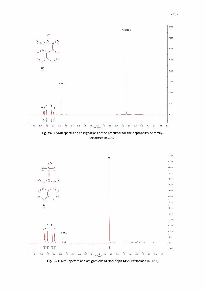
Due to solubility problems in ε-CL of the bromo-substituted NonINaph-MSA (see
p. 52), another version of the precursor was prepared. This new version would have an
alkoxy substituent instead of bromine, and the solubility in ε-CL may improve (Fig. 28).
The reaction was performed in two steps as the reactivity of the N-hydroxylamine could
be problematic. The introduction of a hexyl chain was performed through an Ullman
condensation. Sodium hexylate was prepared from 1-Hexanol using metallic sodium,
and after the bubbling stopped the precursor, copper (I) bromide and ethyl acetate
were added to perform the condensation following the description of the work of
Sambiagio et al[23]. However, the product did not precipitate from the hexanol, and
evaporating the solvent without degrading the compound proved impossible;
precipitating the compound using other solvents was also useless. After two consecutive
chromatographic columns the amount of hexanol was reduced greatly, but the amount
of compound left was negligible too. As it was deemed inviable to continue with the
isolation of that compound, and taking into account that the process to create the
alkoxy-precursor had taken up to ten days with no real possibility of obtaining a
significative amount of product, this line was given up.
Fig. 28. Structure of the Non Ionic precursor
containing the alkoxy chain.
- 46 -
Acetone
CHCl3
854
7, 9
Fig. 29. H-NMR spectra and assignations of the precursor for the napthhalimide family.
Performed in CDCl3.
21
8
CHCl3
54
7, 9
Fig. 30. H-NMR spectra and assignations of NonINaph-MSA. Performed in CDCl3.
- 47 -
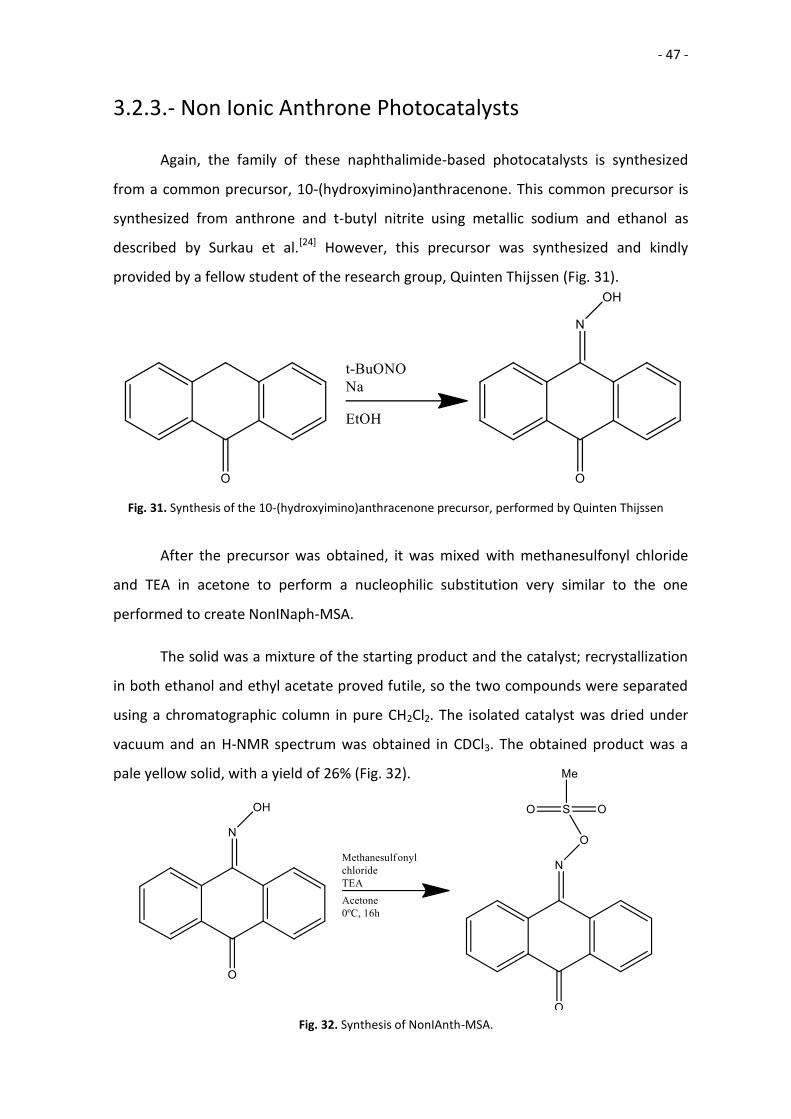
3.2.3.- Non Ionic Anthrone Photocatalysts
Again, the family of these naphthalimide-based photocatalysts is synthesized
from a common precursor, 10-(hydroxyimino)anthracenone. This common precursor is
synthesized from anthrone and t-butyl nitrite using metallic sodium and ethanol as
described by Surkau et al.[24] However, this precursor was synthesized and kindly
provided by a fellow student of the research group, Quinten Thijssen (Fig. 31).
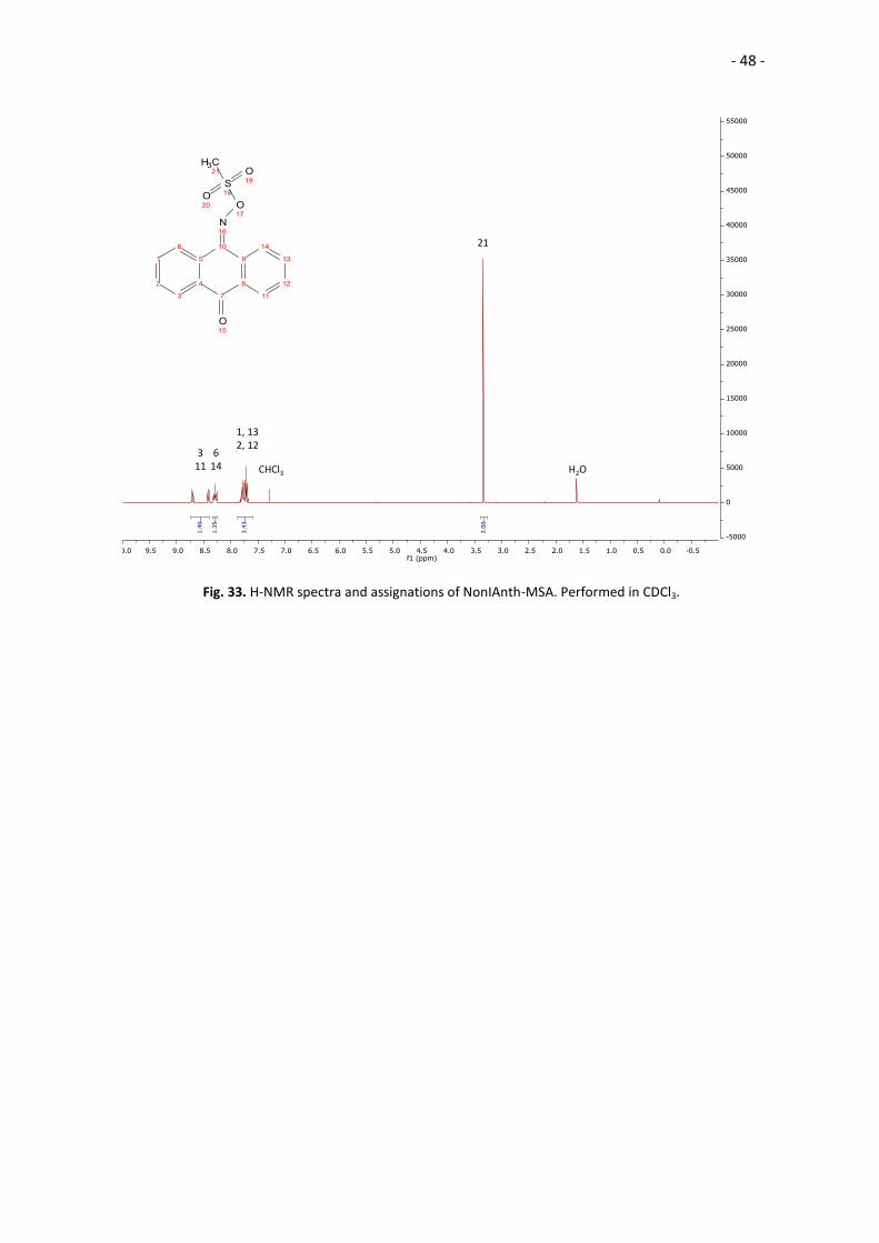
After the precursor was obtained, it was mixed with methanesulfonyl chloride
and TEA in acetone to perform a nucleophilic substitution very similar to the one
performed to create NonINaph-MSA.
The solid was a mixture of the starting product and the catalyst; recrystallization
in both ethanol and ethyl acetate proved futile, so the two compounds were separated
using a chromatographic column in pure CH2Cl2. The isolated catalyst was dried under
vacuum and an H-NMR spectrum was obtained in CDCl3. The obtained product was a
pale yellow solid, with a yield of 26% (Fig. 32).
Fig. 31. Synthesis of the 10-(hydroxyimino)anthracenone precursor, performed by Quinten Thijssen
Fig. 32. Synthesis of NonIAnth-MSA.
- 48 -
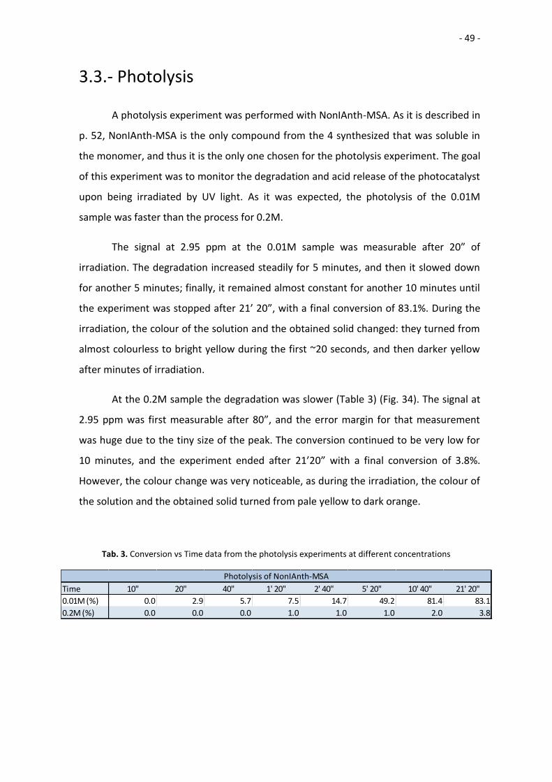
21
1, 132, 12
614
311 H2OCHCl3
Fig. 33. H-NMR spectra and assignations of NonIAnth-MSA. Performed in CDCl3.
- 49 -
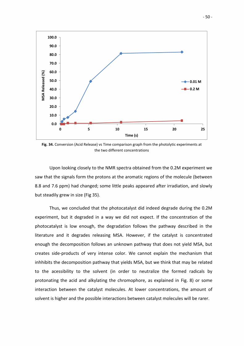
3.3.- Photolysis
A photolysis experiment was performed with NonIAnth-MSA. As it is described in
p. 52, NonIAnth-MSA is the only compound from the 4 synthesized that was soluble in
the monomer, and thus it is the only one chosen for the photolysis experiment. The goal
of this experiment was to monitor the degradation and acid release of the photocatalyst
upon being irradiated by UV light. As it was expected, the photolysis of the 0.01M
sample was faster than the process for 0.2M.
The signal at 2.95 ppm at the 0.01M sample was measurable after 20” of
irradiation. The degradation increased steadily for 5 minutes, and then it slowed down
for another 5 minutes; finally, it remained almost constant for another 10 minutes until
the experiment was stopped after 21’ 20”, with a final conversion of 83.1%. During the
irradiation, the colour of the solution and the obtained solid changed: they turned from
almost colourless to bright yellow during the first ~20 seconds, and then darker yellow
after minutes of irradiation.
At the 0.2M sample the degradation was slower (Table 3) (Fig. 34). The signal at
2.95 ppm was first measurable after 80”, and the error margin for that measurement
was huge due to the tiny size of the peak. The conversion continued to be very low for
10 minutes, and the experiment ended after 21’20” with a final conversion of 3.8%.
However, the colour change was very noticeable, as during the irradiation, the colour of
the solution and the obtained solid turned from pale yellow to dark orange.
Time 10" 20" 40" 1' 20" 2' 40" 5' 20" 10' 40" 21' 20"
0.01M (%) 0.0 2.9 5.7 7.5 14.7 49.2 81.4 83.1
0.2M (%) 0.0 0.0 0.0 1.0 1.0 1.0 2.0 3.8
Photolysis of NonIAnth-MSA
Tab. 3. Conversion vs Time data from the photolysis experiments at different concentrations
- 50 -
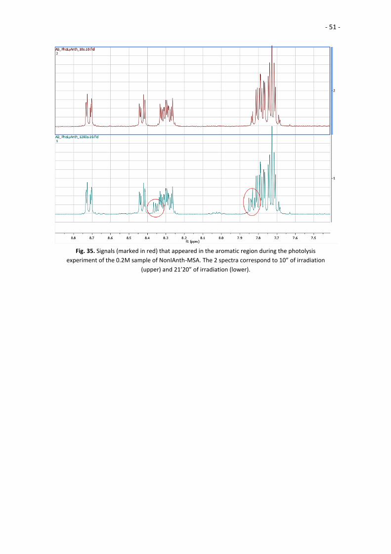
Upon looking closely to the NMR spectra obtained from the 0.2M experiment we
saw that the signals form the protons at the aromatic regions of the molecule (between
8.8 and 7.6 ppm) had changed; some little peaks appeared after irradiation, and slowly
but steadily grew in size (Fig 35).
Thus, we concluded that the photocatalyst did indeed degrade during the 0.2M
experiment, but it degraded in a way we did not expect. If the concentration of the
photocatalyst is low enough, the degradation follows the pathway described in the
literature and it degrades releasing MSA. However, if the catalyst is concentrated
enough the decomposition follows an unknown pathway that does not yield MSA, but
creates side-products of very intense color. We cannot explain the mechanism that
inhhibits the decomposition pathway that yields MSA, but we think that may be related
to the acessibility to the solvent (in order to neutralize the formed radicals by
protonating the acid and alkylating the chromophore, as explained in Fig. 8) or some
interaction between the catalyst molecules. At lower concentrations, the amount of
solvent is higher and the possible interactions between catalyst molecules will be rarer.
0.0
10.0
20.0
30.0
40.0
50.0
60.0
70.0
80.0
90.0
100.0
0 5 10 15 20 25
MSA
Re
lea
sed
(%
)
Time (s)
0.01 M
0.2 M
Fig. 34. Conversion (Acid Release) vs Time comparison graph from the photolytic experiments at
the two different concentrations
- 51 -
Fig. 35. Signals (marked in red) that appeared in the aromatic region during the photolysis
experiment of the 0.2M sample of NonIAnth-MSA. The 2 spectra correspond to 10” of irradiation
(upper) and 21’20” of irradiation (lower).
- 52 -
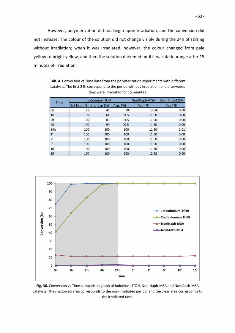
3.4.- Polymerization by Photocatalysts
Finally, the compounds were used to try to catalyse the ROP of ε-CL. As the final
goal of these compounds is the controlled catalysis of the cationic ROP of ε-CL, this final
experiment was designed to test the catalytic power of the photocatalyst when
irradiated with UV light. These results would provide information about the behaviour
of the photocatalysts under irradiation when mixed with the monomer-initiator
formulation, and about the possible viability of the compounds for stereolithography
techniques. As described in the experimental procedure, the stability experiment was
repeated twice for Iodonium-TfOH. In both cases, the sample taken just after sonication
showed that the polymerization had already begun; in the first experiment, with the
different efforts to try to solubilize the photocatalyst, the initial conversion had a value
of 75%. After 1h without irradiation the conversion value increased to 99%, and after 2h
the polymerization conversion was of 100%. Because of this, the irradiation had no
effect on the conversion as every sample reported 100% of conversion. In the second
experiment, the starting conversion was of 41%, and it constantly increased after 1, 2
and 4h of stirring without irradiation. After 24h the conversion was complete, with
100% of the monomer having reacted, and again the irradiation had no effect on the
conversion as every sample reported 100% of conversion. The colour of the yellow
suspension did not change during the 24h of stirring without irradiation neither after 15
minutes under UV light.
NonINaph-MSA was not soluble in ε-CL; after mixing it with a Vortex machine a
uniform suspension was obtained. This 2.5% molar ratio mixture of NonINaph-MSA,
monomer and initiator was stable for 24h without irradiation: the conversion did not
increase during that time. However, it proved not sensitive to UV irradiation, as after 15
minutes of irradiation the conversion did not increase. The base conversion was ~13%.
The colour of the yellow suspension did not change during the 24h of stirring without
irradiation neither after 15 minutes under UV light.
NonIAnth-MSA was soluble in ε-CL after mixing it for 30” with a Vortex machine.
The mixture proved stable for 24h, as the conversion did not increase (barring the error
from the analysis of the H-NMR spectra) during the first 24h without irradiation.
- 53 -
However, polymerization did not begin upon irradiation, and the conversion did
not increase. The colour of the solution did not change visibly during the 24h of stirring
without irradiation; when it was irradiated, however, the colour changed from pale
yellow to bright yellow, and then the solution darkened until it was dark orange after 15
minutes of irradiation.
NonINaph-MSA NonIAnth-MSA
1st Exp. (%) 2nd Exp (%) Avg. (%) Avg (%) Avg (%)0h 75 41 58 13.04 0.00
1h 99 64 81.5 11.50 0.00
2h 100 83 91.5 11.50 0.00
4h 100 99 99.5 11.50 0.99
24h 100 100 100 11.50 1.01
1' 100 100 100 11.50 0.00
2' 100 100 100 11.50 0.00
5' 100 100 100 11.50 0.00
10' 100 100 100 11.50 0.00
15' 100 100 100 12.28 0.00
Iodonium-TfOHTime
Tab. 4. Conversion vs Time data from the polymerization experiments with different
catalysts. The first 24h correspond to the period without irradiation, and afterwards
they were irradiated for 15 minutes.
Fig. 36. Conversion vs Time comparison graph of Iodonium-TfOH, NonINaph-MSA and NonIAnth-MSA
catalysts. The shadowed area corresponds to the non-irradiated period, and the clear area corresponds to
the irradiated time.
0
10
20
30
40
50
60
70
80
90
100
0h 1h 2h 4h 24h 1' 2' 5' 10' 15'
Co
nve
rsio
n (
%)
Time
1st Iodonium-TfOH
2nd Iodonium TfOH
NonINaph-MSA
NonIAnth-MSA
- 54 -
In the Iodonium-TfOH tests, it is clear that the compound decomposed
before irradiation. As mentioned above, the methods tried to solubilize the compound
accelerated its decomposition. With a conversion of 83% at 2 hours without irradiation,
the mixture of photocatalyst, initiator and monomer at 2.5% molar ratio is too unstable
to be used properly. The mixture stayed liquid probably due to the short length of the
polymer chains, but with the NMR method used in this project it could not be measured
or proved; by comparing the peaks at 4.1 and 3.9 ppm we can only measure how much
of the monomer has and has not reacted; this technique does not give information on
the length of the chains or its’ distribution.
In the NonINaph-MSA test, it can be seen that the mixture was stable but not
sensitive to irradiation. The base conversion value of 13% was caused by a contaminated
monomer; an H-NMR spectrum of the pure monomer was made and it showed the
same conversion value.
The same thing happened with NonIAnth-MSA: the mixture was stable without
irradiation, but it did not initiate polymerization when exposed to the UV light. As in the
photolysis experiment with the 0.2M sample, it could be said that the photocatalyst
degraded (due to the change in colour and the visibly different NMR spectra in the
aromatic region) but following a pathway that did not yield MSA, and thus did not
catalyse the polymerization.

- 55 -
4.- Conclusions
During this project four new compounds have been synthesized. These new
compounds have been purified, characterized and studied for their application in ROP
processes for ε-CL. However, during the tests these compounds have not been able to
catalyse the polymerization. These results show the importance of solubility and make
evident one of the big problems with bulk polymerization. Of the 4 compounds that
were developed, only one was soluble in ε-Caprolactone, and the best that could be
achieved with the other three was to form a uniform suspension in the monomer. Apart
from the clear storage problems that an heterogeneous mixture presents (with non-
uniform distribution and precipitation issues), the inability to dissolve the catalysts may
result in problems with the release of the acid into the monomer medium, or the
inefficient photolysis dude to a reduced surface/mass ratio. With thermal stability and
long shelf life in their favour, the usefulness for bulk polymerization of ionic PAGs may
be greatly reduced by their low solubility in the monomers.
The described decomposition pathways of the photocatalyst seem like are only
valid in low concentrations, and that those pathways may be inhibited in some way in
higher concentrations. This alone may not be a problem, and using lower concentrations
of catalyst may help with its distribution in the monomer and the final properties of the
obtained material. However, one of the disadvantages of organocatalysts compared to
metallic/organometallic catalysts is the high amount of catalyst needed to perform the
same reaction or achieve similar reaction speeds. One the goals of the project was to
find a photocatalyst that could achieve high conversion values in short timespans,
preferably under 15 minutes; the active catalysts were able to obtain those values when
used to perform bulk polymerizations with a molar percentage of 5% and 2.5% but no
tests were performed using a concentration as low as 0.1% (the equivalent of 0.01M).
Lowering even more the reducing even more the amount of photocatalyst would result
in too long polymerization times, so long that it would not be useful for 3D printing or
lithography.

- 56 -
The following steps on the development of organic photocatalyst for bulk ionic
polymerizations oriented to 3D printing should be directed to exploring the catalysts
that are known to be soluble in monomers (such as the anthrone-based iminosulfates)
They also should be directed to the development and optimization of polymerization
reactions in conditions of low catalyst ratios to prevent the problems of high-
concentration-photolysis encountered during this project, and check if fast enough
polymerizations under those conditions are possible.
- 57 -
4.- Conclusiones
A lo largo de este proyecto cuatro nuevos compuestos han sido sintetizados.
Estos compuestos han sido purificados, caracterizados y se ha estudiado la posibilidad
de utilizarlos en la ROP de la ε-CL. No obstante, durante las pruebas ninguno de los
compuestos ha sido capaz de catalizar la polimerización. Estos resultados demuestran la
importancia de la solubilidad, y evidencian uno de los mayores problemas de la
polimerización en masa. De los 4 compuestos desarrollados en este proyecto, solamente
uno de ellos era soluble en ε-Caprolactona, y lo mejor que se pudo conseguir con los
demás fue la formación de una suspensión heterogénea pero uniforme en el
monómero. Más allá del evidente problema de almacenamiento que presentan las
mezclas heterogéneas (con posibles distribuciones no uniformes y problemas de
precipitación del catalizador), la imposibilidad de disolver los catalizadores puede
resultar en problemas de liberación del ácido ya generado al medio del monómero y en
absorciones poco eficientes de la radiación UV debido a un ratio superficie/masa
reducido. Aún con una buena estabilidad térmica y una larga vida de almacenamiento a
su favor, la utilidad para la polimerización en masa de los fotogeneradores ácidos
iónicos puede verse significativamente reducida por su escasa solubilidad en los
monómeros a utilizar.
Las vías de descomposición descritas parecen válidas solamente en condiciones
de baja concentración, y que dichas vías se ven inhibidas en condiciones de mayor
concentración. Esto por sí mismo puede no ser un problema, y utilizar menores
concentraciones de catalizador puede mejorar la distribución de éste en el medio y las
propiedades finales del material obtenido. No obstante, una de las desventajas de la
organocatálisis comparada con los catalizadores metálicos y organometálicos es la
necesidad de emplear cantidades mayores de catalizador para llevar a cabo las mismas
reacciones o alcanzar velocidades de reacción similares. Uno de los objetivos de este
proyecto era el desarrollo de un fotocatalizador capaz de obtener altos valores de
conversión en breves tiempos de reacción, preferiblemente por debajo de los 15
minutos; los catalizadores activos eran capaces de llevar a cabo polimerizaciones en
masa y obtener dichas conversiones en esas franjas de tiempo cuando se usaron en
- 58 -
proporciones de 5% y 2.5% molar. No se hicieron pruebas con concentraciones de
catalizador tan bajas como 0.1% (el equivalente de 0.01M en ε-Caprolactona) Reducir
todavía más la cantidad de fotocatalizador podría resultar en tiempos de polimerización
demasiado largos; tan largos que no serían útiles para impresión 3D o litografía.
Los próximos pasos en el desarrollo de fotocatalizadores orgánicos para la
polimerización iónica en masa orientada a impresión 3D debería centrarse en explorar
los catalizadores cuya capacidad de disolverse en el monómero es conocida (como los
iminosulfatos basados en antrona). También centrarse en el desarrollo y optimización
de polimerizaciones en condiciones de muy bajo ratio de catalizador para evitar los
problemas de fotólisis asociados a altas concentraciones hallados durante este
proyecto, para ver si dichas condiciones permiten una polimerización lo suficientemente
rápida.
- 59 -
5.- Bibliography
1. Suyama, K.; Shirai, M. “Photobase generators: Recent progress and application trend in polymer systems” Progress in
Polymer Science 34 (2009): 194 – 209
2. Tack, P.; Victor, J.; Annemans, L. “3D-printing techniques in a medical setting: a systematic literature review” BioMed
Engineering OnLine 15 (2016): 115 – 136
3. Barker, I.; Dove, A. “Triarylsulfonium hexafluorophosphate salts as photoactivated acidic catalysts for ring-opening
polymerisation” Chemical Communications 49 (2013): 1205 - 1207
4. Matsuda, T.; Mizutani, M.; Arnold, S. “Molecular Design of Photocurable Liquid Biodegradable Copolymers. 1. Synthesis
and Photocuring Characteristics” Macromolecules 33 (2000): 795 - 800
5. Bossion, A.; Heifferon, K.V.; Meabe, L.; Zivic, N.; Taton, D.; Hedrick, J.L.; Long, T.E.; Sardon, H. “Opportunities for
organocatalysis in polymer synthesis via step-growth methods” Progress in Polymer Science 90 (2019) 164 - 210
6. Ottou, W.N.; Sardon, H.; Mecerreyes, D.; Vignolle, J.; Taton, D. “Update and challenges in organo-mediated
polymerization reactions” Progress in Polymer Science 56 (2016): 64 – 115
7. Martin, C.; Rapenne, G.; Nakashima, T.; Kawai, T. “Recent progress in development of photoacid generators” Journal of
Photochemistry and Photobiology C 34 (2018): 41-51
8. Fu, C.; Xu, J.; Boyer, C. “Photoacid-mediated Ring Opening Polymerization Driven by Visible Light” Chemical
Communications 52 (2016): 7126 – 7129
9. Fukushima, K. “Poly(trimethylene carbonate)-based polymers engineered for biodegradable functional biomaterials”
Biomaterials Science 4 (2016): 9 - 24
10. Coady, D.; Horn, H.; Jones, G.; Sardon, H.; Engler, A.; Waymouth, R.; Rice, J.; Yang, Y.; Hedrick, J. “Polymerizing Base
Sensitive Cyclic Carbonates Using Acid Catalysis” ACS MacroLetters 2 (2013): 306 - 312
11. Makiguchi, K.; Ogasawara, Y.; Kikuchi, S.; Satoh, T.; Kakuchi, T. “Diphenyl Phosphate as an Efficient Acidic Organocatalyst
for Controlled/Living Ring-Opening Polymerization of Trimethylene Carbonates Leading to Block, End-Functionalized, and
Macrocyclic Polycarbonates” Macromolecules 46 (2013): 1772 - 1782
12. Delcroix, D.; Martin-Vaca, B.; Bourissou, D.; Navarro, C. “Ring-Opening Polymerization of Trimethylene Carbonate
Catalyzed by Methanesulfonic Acid: Activated Monomer versus Active Chain End Mechanisms” Macromolecules 43
(2010): 8828 - 8835
13. Gazeau-Bureau, S.; Delcroix, D.; Martín-Vaca, B.; Bourissou, D.; Navarro, C.; Magnet, S. “Organo-Catalyzed ROP of ε-
Caprolactone: Methanesulfonic Acid Competes with Trifluoromethanesulfonic Acid” Macromolecules 42 (2008) 3782 -
3784
- 60 -
14. Makiguchi, K.; Kikuchi, S.; Satoh, T.; Kakuchi, T. “Synthesis of Block and End-Functionalized Polyesters by Triflimide-
Catalyzed Ring-Opening Polymerization of ε-Caprolactone, 1,5-Dioxepan-2-one, and rac-Lactide” Polymer Chemistry 51
(2013): 2455 – 2463
15. Harris, D.C., Bartolucci, M.D. “Symmetry and Spectroscopy: An Introduction to Vibrational and Electronic Spectroscopy”
Oxford University Press (1989): 4025 – 4034
16. Crivello, J.V. “Cationic Polymerization – Iodonium and Sulfonium Salt Photoinitiators” Advances in Polymer Science 62
(1984)
17. Dektar, J.L.; Hacker, N.P. “Photochemistry of Diaryliodonium Salts” Journal of Organic Chemistry 55 (1990): 639 - 647
18. Zivic, N. “Synthèse de Naphthalimides et Dicétopyrrolopyrroles Originaux pour les Photomolymérisations Radicalaire et
Cationique dans des Conditions d’Irradiation Douces” Ph.D. Thesis (2017):
a. p. 142
b. p. 221-222
19. Iwashima, C.; Imai, G.; Okamura, H.; Tsunooka, M.; Shirai, M. “Synthesis of 1- and g-Line Sensitive Photoacid Generators
and Their Application to Photopolymer Systems” Journal of Photomolymer Science and Technology 16 (2003): 91-96
20. Ortica, F.; Scaiano, J.C.; Pohlers, G.; Cameron, J.F.; Zampini, A. “Laser Flash Photolysis Study of Two Aromatic N-
Oxymidosulfonate Photoacid Generators” Chemistry of Materials 12 (2000) 414-420
21. Sun, X.; Jin, M.; We, X.; Pan, H.; Wan, D.; Pu, H. “Bis-Substituted Thiophene-Containing Oxime Sulfonates Photoacid
Generators for Cationic Polymerization Under UV-Visible LED Irradiation” Journal of Polymer Science: Polymer Chemistry
56 (2018): 776-782
22. Campos, J.M.; Ribeiro, M.R.; Ribeiro, M.F.; Deffieux, A.; Peruch, F. “Copolymerisation of ε-Caprolactone and trimethylene
carbonate catalysed by methanesulfonic acid” European Polymer Journal 49 (2013): 4025 – 4034
23. Sambiagio, C.; Marsden, S.P.; Blacker, A.J.; McGowan, P.C. “Copper catalysed Ulmann type chemistry: rom mechanistic
aspects to modern development" Chemical Society Reviews 43 (2014) 3525-3550
24. Surkau, G.; Böhm, K.j.; Müller, K.; Prinz, H. “Synthesis, antiproliferative activity and inhibition of tubulin polymerization by
anthracenone –based oxime derivatives” European Journal of Medical Chemistry 45 (2010) 3354-3364