Design of Gas Piping Distribution Systems Consisting of Long
13
Design of Gas Piping Distribution Systems Consisting of Long Pipes Under Any Vacuum Conditions 64 th IUVSTA Workshop on Practical Applications and Methods of Gas Dynamics for Vacuum Science and Technology Leinsweiler, Germany, 16 – 19/05/2011 Serafeim Misdanitis and Dimitris Valougeorgis [email protected]; [email protected] Department of Mechanical Engineering University of Thessaly, Volos, Greece
Transcript of Design of Gas Piping Distribution Systems Consisting of Long
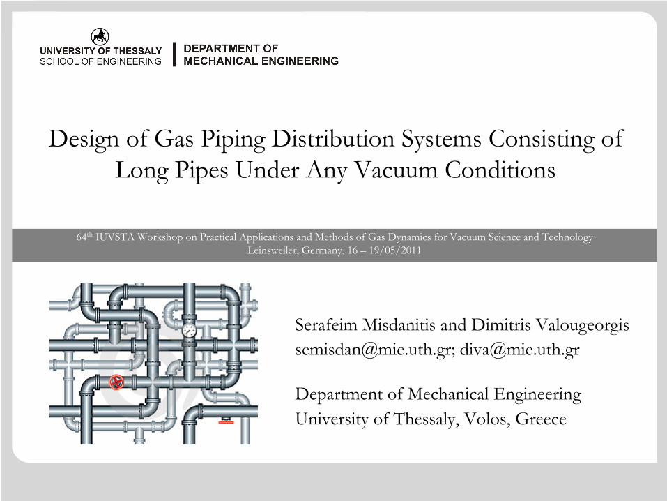
Design of Gas Piping Distribution Systems Consisting of Long Pipes Under Any Vacuum Conditions
64th IUVSTA Workshop on Practical Applications and Methods of Gas Dynamics for Vacuum Science and TechnologyLeinsweiler, Germany, 16 – 19/05/2011
Serafeim Misdanitis and Dimitris [email protected]; [email protected]
Department of Mechanical Engineering University of Thessaly, Volos, Greece
2 18.05.2011 UNIVERSITY OF THESSALYSCHOOL OF ENGINEERING64th IUVSTA Workshop
Introduction
Rarefied gas flows in long circular channels have been extensively investigated via linear kinetic theory from the 1960s, implementing various semi-analytical and numerical schemes.
In many applications however, the rarefied gaseous distribution system is consisting not of a single channel but of many channels accordingly combined to form a network.
Such distribution systems are commonly found in several technological fields including
vacuum pumping, metrology, industrial aerosol, porous media and microfluidics.
3 18.05.2011 UNIVERSITY OF THESSALYSCHOOL OF ENGINEERING64th IUVSTA Workshop
Introduction
Computational algorithms dedicated to the design of gas pipe networks (e.g., compressed air, natural gas, etc.) in the viscous regime are well developed, while corresponding tools for the design of gaseous pipe networks operating under any (e.g. low, medium and high) vacuum conditions are very limited.
It is seen that in several applicationsthe gas distribution systems may be represented by complex networks consisting of short and long channels of various cross sections and
the gas flows may be in the whole range of the Knudsen number from the free molecular through the transition up to the viscous regime.
The objective is to compute the mass flow rate and the conductance through each tube and the pressure head at each node of the network, provided that the geometry of each channel of the network is given.
4 18.05.2011 UNIVERSITY OF THESSALYSCHOOL OF ENGINEERING64th IUVSTA Workshop
Formulation of the algorithm
A typical pipe network may be considered as a directed linear graph consisting of a finite number of pipe sections interconnected in a specified configuration.
Each pipe is characterized of its length L, diameter D and some roughness. A point where two or more pipes are joined is known as a junction node or simply as a node.
The closed path uniquely formed by adjacent pipes is a loop, while the open path connecting two fixed-grade nodes is a pseudo-loop. A fixed grade node is a node where a consistent energy grade is maintained (e.g. a constant pressure reservoir).
For a well-defined network with p pipes, n junction nodes, l loops and f fixed-grade nodes the following relation holds:
1p n l f= + + −
5 18.05.2011 UNIVERSITY OF THESSALYSCHOOL OF ENGINEERING64th IUVSTA Workshop
Formulation of the algorithm
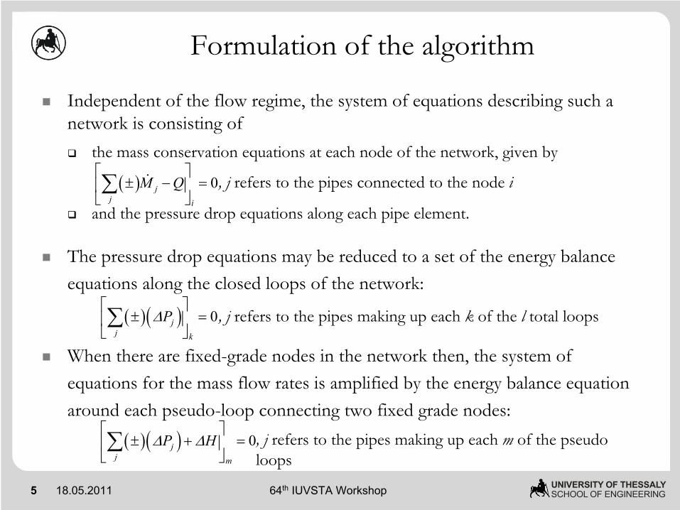
Independent of the flow regime, the system of equations describing such a network is consisting of
the mass conservation equations at each node of the network, given by
and the pressure drop equations along each pipe element.
The pressure drop equations may be reduced to a set of the energy balance equations along the closed loops of the network:
When there are fixed-grade nodes in the network then, the system of equations for the mass flow rates is amplified by the energy balance equation around each pseudo-loop connecting two fixed grade nodes:
( ) 0jj i
M Q⎡ ⎤
± − =⎢ ⎥⎣ ⎦∑
( )( ) 0jj k
PΔ⎡ ⎤
± =⎢ ⎥⎣ ⎦∑
, j
refers to the pipes connected to the node i
, j
refers to the pipes making up each k of the l total loops
( )( ) 0jj m
P HΔ Δ⎡ ⎤
± + =⎢ ⎥⎣ ⎦∑ , j
refers to the pipes making up each m of the pseudo
loops
6 18.05.2011 UNIVERSITY OF THESSALYSCHOOL OF ENGINEERING64th IUVSTA Workshop
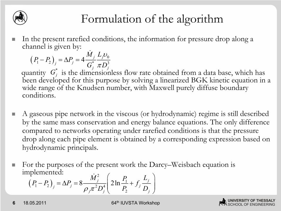
Formulation of the algorithmIn the present rarefied conditions, the information for pressure drop along a channel is given by:
quantity is the dimensionless flow rate obtained from a data base, which has been developed for this purpose by solving a linearized BGK kinetic equation in a wide range of the Knudsen number, with Maxwell purely diffuse boundary conditions.
A gaseous pipe network in the viscous (or hydrodynamic) regime is still described by the same mass conservation and energy balance equations. The only difference compared to networks operating under rarefied conditions is that the pressure drop along each pipe element is obtained by a corresponding expression based on hydrodynamic principals.
For the purposes of the present work the Darcy–Weisbach equation is implemented:
( ) 01 2 * 34 j j
jjj j
M LP P P
G Dυ
π− = Δ =
*jG
( )2
11 2 2 4
2
8 2lnj jj jj
j j j
M LPP P P fD P Dρ π
⎛ ⎞− = Δ = +⎜ ⎟⎜ ⎟
⎝ ⎠
7 18.05.2011 UNIVERSITY OF THESSALYSCHOOL OF ENGINEERING64th IUVSTA Workshop
Design of a network under vacuum conditions
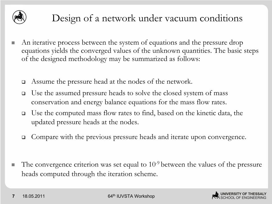
An iterative process between the system of equations and the pressure drop equations yields the converged values of the unknown quantities. The basic steps of the designed methodology may be summarized as follows:
Assume the pressure head at the nodes of the network. Use the assumed pressure heads to solve the closed system of mass conservation and energy balance equations for the mass flow rates. Use the computed mass flow rates to find, based on the kinetic data, the updated pressure heads at the nodes.
Compare with the previous pressure heads and iterate upon convergence.
The convergence criterion was set equal to 10-9 between the values of the pressure heads computed through the iteration scheme.
8 18.05.2011 UNIVERSITY OF THESSALYSCHOOL OF ENGINEERING64th IUVSTA Workshop
2 3 42M 3M
23M
14Q
6Q2P 3P 4P
26M
29M28M
16M
18M 19M
25M
22M
19
262516
17 1819P
26P25P16P
17P18P
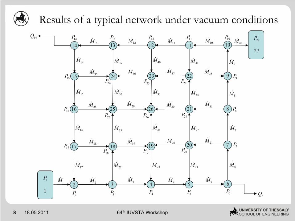
Results of a typical network under vacuum conditions
4 5 6
20 7
21 8
232415 22 9
121314 11 10
5P 6P
4M 5M
20M 21M
30M 31M
37M 38M
11M 10M13M 12M
35M 36M15P
15M 32M
39M14M
24M 6M
7M
8M
9M41M40M
33M34M
27M
17M
42M
1M
8P
9P
10P11P12P13P14P
7P
21P
24P 23P 22P
20P
27P
27
1P
1
9 18.05.2011 UNIVERSITY OF THESSALYSCHOOL OF ENGINEERING64th IUVSTA Workshop
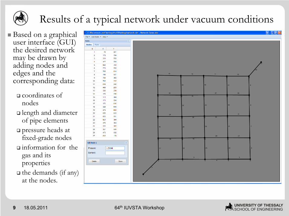
Based on a graphical user interface (GUI) the desired network may be drawn by adding nodes and edges and the corresponding data:
coordinates of nodes length and diameter of pipe elementspressure heads at fixed-grade nodesinformation for the gas and its propertiesthe demands (if any) at the nodes.
Results of a typical network under vacuum conditions
10 18.05.2011 UNIVERSITY OF THESSALYSCHOOL OF ENGINEERING64th IUVSTA Workshop
Results of a typical network under vacuum conditions
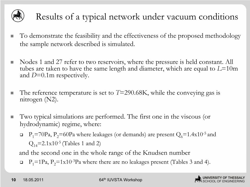
To demonstrate the feasibility and the effectiveness of the proposed methodology the sample network described is simulated.
Nodes 1 and 27 refer to two reservoirs, where the pressure is held constant. All tubes are taken to have the same length and diameter, which are equal to L=10m and D=0.1m respectively.
The reference temperature is set to T=290.68K, while the conveying gas is nitrogen (N2).
Two typical simulations are performed. The first one in the viscous (or hydrodynamic) regime, where:
P1=70Pa, P2=60Pa where leakages (or demands) are present Q6=1.4x10⁻⁵ and Q14=2.1x10⁻⁵ (Tables 1 and 2)
and the second one in the whole range of the Knudsen numberP1=1Pa, P2=1x10⁻³Pa where there are no leakages present (Tables 3 and 4).
11 18.05.2011 UNIVERSITY OF THESSALYSCHOOL OF ENGINEERING64th IUVSTA Workshop
Results of a typical network under vacuum conditions
Nodenumber
Local Kn
Head Pressure [Pa]
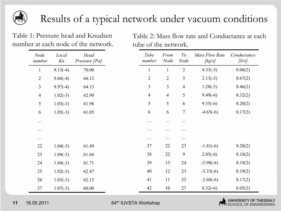
1 9.13(-4) 70.00
2 9.66(-4) 66.12
3 9.97(-4) 64.13
4 1.02(-3) 62.90
5 1.03(-3) 61.98
6 1.05(-3) 61.05
…
…
…
22 1.04(-3) 61.49
23 1.04(-3) 61.66
24 1.04(-3) 61.71
25 1.02(-3) 62.47
26 1.03(-3) 62.12
27 1.07(-3) 60.00
Tubenumber
FromNode
To Node
Mass Flow Rate[kg/s]
Conductance[lt/s]
1 1 2 4.33(-5) 9.06(2)
2 2 3 2.13(-5) 8.67(2)
3 3 4 1.28(-5) 8.46(2)
4 4 5 9.49(-6) 8.32(2)
5 5 6 9.35(-6) 8.20(2)
6 6 7 -4.65(-6) 8.17(2)
… … …
… … …
… … …
37 22 23 -1.81(-6) 8.20(2)
38 22 9 2.05(-6) 8.18(2)
39 13 24 -5.98(-6) 8.18(2)
40 12 23 -3.33(-6) 8.19(2)
41 11 22 -2.68(-6) 8.17(2)
42 10 27 8.32(-6) 8.05(2)
Table 1: Pressure head and Knudsen number at each node of the network.
Table 2: Mass flow rate and Conductance at each tube of the network.
12 18.05.2011 UNIVERSITY OF THESSALYSCHOOL OF ENGINEERING64th IUVSTA Workshop
Results of a typical network under vacuum conditions
Nodenumber
Local Kn
Head Pressure [Pa]
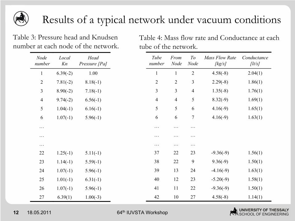
1 6.39(-2) 1.00
2 7.81(-2) 8.18(-1)
3 8.90(-2) 7.18(-1)
4 9.74(-2) 6.56(-1)
5 1.04(-1) 6.16(-1)
6 1.07(-1) 5.96(-1)
…
…
…
22 1.25(-1) 5.11(-1)
23 1.14(-1) 5.59(-1)
24 1.07(-1) 5.96(-1)
25 1.01(-1) 6.31(-1)
26 1.07(-1) 5.96(-1)
27 6.39(1) 1.00(-3)
Tubenumber
FromNode
To Node
Mass Flow Rate[kg/s]
Conductance[lt/s]
1 1 2 4.58(-8) 2.04(1)
2 2 3 2.29(-8) 1.86(1)
3 3 4 1.35(-8) 1.76(1)
4 4 5 8.32(-9) 1.69(1)
5 5 6 4.16(-9) 1.65(1)
6 6 7 4.16(-9) 1.63(1)
… … …
… … …
… … …
37 22 23 -9.36(-9) 1.56(1)
38 22 9 9.36(-9) 1.50(1)
39 13 24 -4.16(-9) 1.63(1)
40 12 23 -5.20(-9) 1.58(1)
41 11 22 -9.36(-9) 1.50(1)
42 10 27 4.58(-8) 1.14(1)
Table 3: Pressure head and Knudsen number at each node of the network.
Table 4: Mass flow rate and Conductance at each tube of the network.
13 18.05.2011 UNIVERSITY OF THESSALYSCHOOL OF ENGINEERING64th IUVSTA Workshop
Concluding remarks
A novel algorithm has been developed for the design of gaseous distribution systems of any complexity consisting of long tubes based on linear kinetic theory.
In the viscous regime, the algorithm provides very good agreement with similar solvers based on hydrodynamic principals.
The results are valid and accurate in the whole range of the Knudsen number.
The algorithm will be extended to include channels of any cross section and more important, channels of short length.
Further development will include optimization of gaseous micro distribution networks in order to be used as an engineering tool in the design of gas network systems.