1 Specifications Outdoor unit - Zubadan · 4 PIPING-WIRING DIRECTIONS Piping and wiring...
9
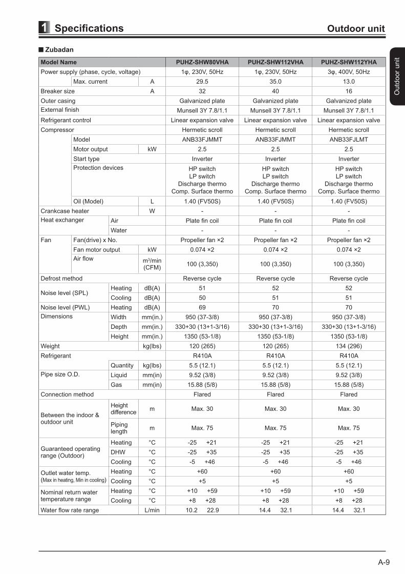
Outdoor unit A-9 Specifications 1 Outdoor unit Zubadan Model Name PUHZ-SHW80VHA PUHZ-SHW112VHA PUHZ-SHW112YHA Power supply (phase, cycle, voltage) 1φ, 230V, 50Hz 1φ, 230V, 50Hz 3φ, 400V, 50Hz Max. current A 29.5 35.0 13.0 Breaker size A 32 40 16 Outer casing Galvanized plate Galvanized plate Galvanized plate External finish Munsell 3Y 7.8/1.1 Munsell 3Y 7.8/1.1 Munsell 3Y 7.8/1.1 Refrigerant control Linear expansion valve Linear expansion valve Linear expansion valve Compressor Hermetic scroll Hermetic scroll Hermetic scroll Model ANB33FJMMT ANB33FJMMT ANB33FJLMT Motor output kW 2.5 2.5 2.5 Start type Inverter Inverter Inverter Protection devices HP switch LP switch Discharge thermo Comp. Surface thermo HP switch LP switch Discharge thermo Comp. Surface thermo HP switch LP switch Discharge thermo Comp. Surface thermo Oil (Model) L 1.40 (FV50S) 1.40 (FV50S) 1.40 (FV50S) Crankcase heater W - - - Heat exchanger Air Plate fin coil Plate fin coil Plate fin coil Water - - - Fan Fan(drive) x No. Propeller fan ×2 Propeller fan ×2 Propeller fan ×2 Fan motor output kW 0.074 ×2 0.074 ×2 0.074 ×2 Air flow m 3 /min (CFM) 100 (3,350) 100 (3,350) 100 (3,350) Defrost method Reverse cycle Reverse cycle Reverse cycle Noise level (SPL) Heating dB(A) 51 52 52 Cooling dB(A) 50 51 51 Noise level (PWL) Heating dB(A) 69 70 70 Dimensions Width mm(in.) 950 (37-3/8) 950 (37-3/8) 950 (37-3/8) Depth mm(in.) 330+30 (13+1-3/16) 330+30 (13+1-3/16) 330+30 (13+1-3/16) Height mm(in.) 1350 (53-1/8) 1350 (53-1/8) 1350 (53-1/8) Weight kg(lbs) 120 (265) 120 (265) 134 (296) Refrigerant R410A R410A R410A Quantity kg(lbs) 5.5 (12.1) 5.5 (12.1) 5.5 (12.1) Pipe size O.D. Liquid mm(in) 9.52 (3/8) 9.52 (3/8) 9.52 (3/8) Gas mm(in) 15.88 (5/8) 15.88 (5/8) 15.88 (5/8) Connection method Flared Flared Flared Between the indoor & outdoor unit Height difference m Max. 30 Max. 30 Max. 30 Piping length m Max. 75 Max. 75 Max. 75 Guaranteed operating range (Outdoor) Heating °C -25 +21 -25 +21 -25 +21 DHW °C -25 +35 -25 +35 -25 +35 Cooling °C -5 +46 -5 +46 -5 +46 Outlet water temp. (Max in heating, Min in cooling) Heating °C +60 +60 +60 Cooling °C +5 +5 +5 Nominal return water temperature range Heating °C +10 +59 +10 +59 +10 +59 Cooling °C +8 +28 +8 +28 +8 +28 Water flow rate range L/min 10.2 22.9 14.4 32.1 14.4 32.1
Transcript of 1 Specifications Outdoor unit - Zubadan · 4 PIPING-WIRING DIRECTIONS Piping and wiring...
Outd
oor
unit
A-9
Specifications1 Outdoor unit
Zubadan
Model Name PUHZ-SHW80VHA PUHZ-SHW112VHA PUHZ-SHW112YHA
Power supply (phase, cycle, voltage) 1φ, 230V, 50Hz 1φ, 230V, 50Hz 3φ, 400V, 50Hz
Max. current A 29.5 35.0 13.0
Breaker size A 32 40 16
Outer casing Galvanized plate Galvanized plate Galvanized plate
External finish Munsell 3Y 7.8/1.1 Munsell 3Y 7.8/1.1 Munsell 3Y 7.8/1.1
Refrigerant control Linear expansion valve Linear expansion valve Linear expansion valve
Compressor Hermetic scroll Hermetic scroll Hermetic scroll
Model ANB33FJMMT ANB33FJMMT ANB33FJLMT
Motor output kW 2.5 2.5 2.5
Start type Inverter Inverter Inverter
Protection devices HP switch
LP switch
Discharge thermo
Comp. Surface thermo
HP switch
LP switch
Discharge thermo
Comp. Surface thermo
HP switch
LP switch
Discharge thermo
Comp. Surface thermo
Oil (Model) L 1.40 (FV50S) 1.40 (FV50S) 1.40 (FV50S)
Crankcase heater W - - -
Heat exchanger Air Plate fin coil Plate fin coil Plate fin coil
Water - - -
Fan Fan(drive) x No. Propeller fan ×2 Propeller fan ×2 Propeller fan ×2
Fan motor output kW 0.074 ×2 0.074 ×2 0.074 ×2
Air flow m3/min(CFM)
100 (3,350) 100 (3,350) 100 (3,350)
Defrost method Reverse cycle Reverse cycle Reverse cycle
Noise level (SPL)Heating dB(A) 51 52 52
Cooling dB(A) 50 51 51
Noise level (PWL) Heating dB(A) 69 70 70
Dimensions Width mm(in.) 950 (37-3/8) 950 (37-3/8) 950 (37-3/8)
Depth mm(in.) 330+30 (13+1-3/16) 330+30 (13+1-3/16) 330+30 (13+1-3/16)
Height mm(in.) 1350 (53-1/8) 1350 (53-1/8) 1350 (53-1/8)
Weight kg(lbs) 120 (265) 120 (265) 134 (296)
Refrigerant R410A R410A R410A
Quantity kg(lbs) 5.5 (12.1) 5.5 (12.1) 5.5 (12.1)
Pipe size O.D. Liquid mm(in) 9.52 (3/8) 9.52 (3/8) 9.52 (3/8)
Gas mm(in) 15.88 (5/8) 15.88 (5/8) 15.88 (5/8)
Connection method Flared Flared Flared
Between the indoor &outdoor unit
Heightdifference
m Max. 30 Max. 30 Max. 30
Piping length
m Max. 75 Max. 75 Max. 75
Guaranteed operatingrange (Outdoor)
Heating °C -25 +21 -25 +21 -25 +21
DHW °C -25 +35 -25 +35 -25 +35
Cooling °C -5 +46 -5 +46 -5 +46
Outlet water temp.(Max in heating, Min in cooling)
Heating °C +60 +60 +60
Cooling °C +5 +5 +5
Nominal return watertemperature range
Heating °C +10 +59 +10 +59 +10 +59
Cooling °C +8 +28 +8 +28 +8 +28
Water flow rate range L/min 10.2 22.9 14.4 32.1 14.4 32.1
Outd
oor
unit
A-15
Specifications1 Outdoor unit
Zubadan
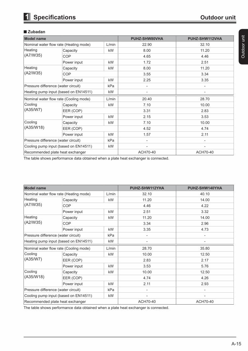
Model name PUHZ-SHW80VHA PUHZ-SHW112VHA
Nominal water flow rate (Heating mode) L/min 22.90 32.10
Heating
(A7/W35)Capacity kW 8.00 11.20
COP 4.65 4.46
Power input kW 1.72 2.51
Heating
(A2/W35)Capacity kW 8.00 11.20
COP 3.55 3.34
Power input kW 2.25 3.35
Pressure difference (water circuit) kPa - -
Heating pump input (based on EN14511) kW - -
Nominal water flow rate (Cooling mode) L/min 20.40 28.70
Cooling
(A35/W7)Capacity kW 7.10 10.00
EER (COP) 3.31 2.83
Power input kW 2.15 3.53
Cooling
(A35/W18)Capacity kW 7.10 10.00
EER (COP) 4.52 4.74
Power input kW 1.57 2.11
Pressure difference (water circuit) kPa - -
Cooling pump input (based on EN14511) kW - -
Recommended plate heat exchanger ACH70-40 ACH70-40
The table shows performance data obtained when a plate heat exchanger is connected.
Model name PUHZ-SHW112YHA PUHZ-SHW140YHA
Nominal water flow rate (Heating mode) L/min 32.10 40.10
Heating
(A7/W35)Capacity kW 11.20 14.00
COP 4.46 4.22
Power input kW 2.51 3.32
Heating
(A2/W35)Capacity kW 11.20 14.00
COP 3.34 2.96
Power input kW 3.35 4.73
Pressure difference (water circuit) kPa - -
Heating pump input (based on EN14511) kW - -
Nominal water flow rate (Cooling mode) L/min 28.70 35.80
Cooling
(A35/W7)Capacity kW 10.00 12.50
EER (COP) 2.83 2.17
Power input kW 3.53 5.76
Cooling
(A35/W18)Capacity kW 10.00 12.50
EER (COP) 4.74 4.26
Power input kW 2.11 2.93
Pressure difference (water circuit) kPa - -
Cooling pump input (based on EN14511) kW - -
Recommended plate heat exchanger ACH70-40 ACH70-40
The table shows performance data obtained when a plate heat exchanger is connected.
Outd
oor u
nit
A-18
Specifications1 Outdoor unit
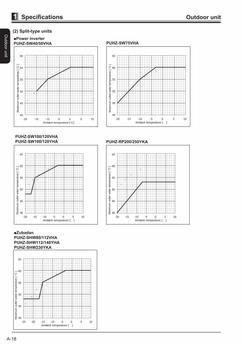
(2) Split-type units
■Power inverter
PUHZ-SW40/50VHA PUHZ-SW75VHA
PUHZ-SW100/120VHA
PUHZ-SW100/120YHA
40
45
50
55
60
65
-20 -15 -10 -5 0 5 10
Ambient temperature [°C]
Ma
xim
um
outle
tw
ate
rte
mpera
ture
[ °C
]
Ma
xim
um
outle
tw
ate
rte
mpera
ture
[ °C
]
40
45
50
55
60
65
-20 -15 -10 -5 0 5 10
Ambient temperature [ ]
Ma
xim
um
outle
tw
ate
rte
mpera
ture
[ °C
]
40
45
50
55
60
65
-20 -15 -10 -5 0 5 10
Ambient temperature [ ]
Ma
xim
um
outle
tw
ate
rte
mpera
ture
[ °C
]
40
45
50
55
60
65
-20 -15 -10 -5 0 5 10
Ambient temperature [ ]
PUHZ-RP200/250YKA
■Zubadan
PUHZ-SHW80/112VHA
PUHZ-SHW112/140YHA
PUHZ-SHW230YKA
Ma
xim
um
outle
tw
ate
rte
mpera
ture
[ °C
]
40
45
50
55
60
65
-25 -20 -15 -10 -5 0 5 10
Ambient temperature [ ]
Outd
oor u
nit
A-28
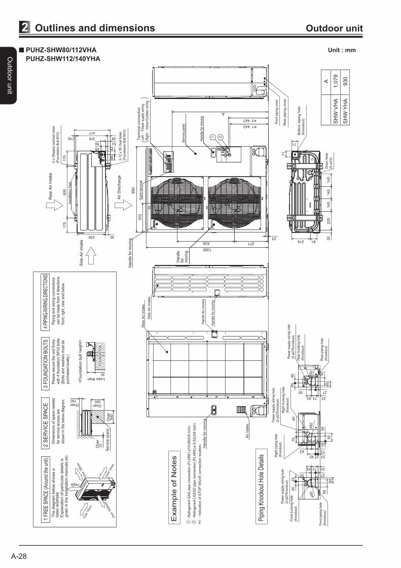
Outlines and dimensions2 Outdoor unit
PUHZ-SHW80/112VHA
PUHZ-SHW112/140YHA
Unit : mm
Handle
for
movi
ng
Sid
e A
ir I
nta
ke
Fro
nt
pip
ing c
ove
r
Rear
pip
ing c
over
Air inta
ke
Rear
Air I
nta
ke
Handle
for
movi
ng
Air D
ischarg
e
Rear
Air I
nta
ke
Sid
e A
ir I
nta
ke
···R
efr
ige
rant
GA
S p
ipe c
onnection (
FLA
RE
)15.8
8(5
/8 inch)
···R
efr
ige
rant
LIQ
UID
pip
e c
onnection (
FLA
RE
) 9
.52(3
/8 inch)
1··
·Indic
ation o
f S
TO
PV
ALV
E c
onnection location.
Exam
ple
of
Note
s
Pip
ing
Kno
ckou
t Hol
e D
etai
ls
600
175
175
330
417
42
66
5356
45
(19) 28370
2-U
Shaped n
otc
hed h
ole
s
(Foundatio
n B
olt
M10)
2-1
2 x
36 O
val h
ole
s
(Foundatio
n B
olt
M10)
Inst
alla
tion
Feet
30
45
40
65
92
2755
237363
Rear
pip
ing h
ole
(Kno
ckout)
Rear
trunki
ng h
ole
(Kno
ckout)
Pow
er
supply
wir
ing h
ole
(2-
27K
no
ckout)
92
19
55
92
75
40
7363
232792Rig
ht
pip
ing h
ole
(Kno
ckout)
Rig
ht
trunki
ng h
ole
(Kno
ckout)
Pow
er
supply
wir
ing h
ole
(2-
27K
no
ckout)
92
92
6545
40
2755
237363
Fro
nt
pip
ing h
ole
(Kno
ckout)
Fro
nt
trunki
ng h
ole
(Kno
ckout)
Pow
er
supply
wir
ing h
ole
(2-
27K
no
ckout)
92
145
145
220
30
145
81219
71
71
Bott
om
pip
ing h
ole
(Kno
ckout)
Dra
in h
ole
(5-
33)
23
SH
W·V
HA
SH
W·Y
HA
1,0
79
A
930
Over
Over Over
Over
Less than
Pip
ing a
nd w
irin
g c
onnect
ions
can b
e m
ade f
rom
4 d
irect
ions:
front,
right,
rear
and b
elo
w.
4 PI
PIN
G-W
IRIN
G D
IREC
TIO
NS
3 F
OU
ND
ATIO
N B
OLT
S2 S
ER
VIC
E S
PA
CE
1 FR
EE
SPA
CE
(Aro
und
the
unit)
Ple
ase
secu
re t
he u
nit
firm
ly
with
4 foundatio
n (
M10)
bolts
.
(Bolts
and w
ash
ers
must
be
purc
hase
d lo
cally
.)
<F
oundation b
olt h
eig
ht>
Dim
ensi
ons
of
space
needed
for
serv
ice a
ccess
are
show
n in
the b
elo
w d
iagra
m.
The d
iagra
m b
elo
w s
how
s a
basic
exam
ple
.
Expla
nation o
f pa
rtic
ula
r deta
ils is
giv
en in t
he insta
llation m
anuals
etc
.
30
FO
UN
DAT
ION
10
500
500150
Serv
ice s
pace
Handle
for
movin
gH
andle
for
movi
ng
Serv
ice p
anel
A
21
1 443
1 447
635 371
1350
322
950
Handle
for
movi
ng
Handle
for
movi
ng
Eart
h t
erm
inal
Term
inal connection
Left
····P
ower
sup
ply
wiri
ng
Rig
ht···
Indo
or/O
utdo
or w
iring
Ove
r 10
mm
Ove
r 10
mm
Ove
r 15
0mm
Ove
r 10
00m
m
FREE
Outd
oor u
nit
A-56
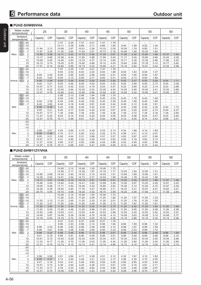
Performance data5 Outdoor unit
PUHZ-SHW80VHA
Water outlet temperature[ ]
25 35 40 45 50 55 60
Ambient temperature[ ]
Capacity COP Capacity COP Capacity COP Capacity COP Capacity COP Capacity COP Capacity COP
Max
-20 - - 7.47 2.25 7.47 2.01 7.47 1.78 - - - - - -
-15 - - 10.11 2.39 9.89 2.11 9.66 1.83 9.44 1.58 9.22 1.34 - -
-10 11.44 3.12 10.89 2.67 10.61 2.36 10.33 2.05 10.09 1.78 9.85 1.51 - -
-7 11.97 3.25 11.35 2.84 11.04 2.51 10.73 2.19 10.48 1.90 10.22 1.62 - -
2 12.88 3.49 12.11 3.22 11.73 2.94 11.35 2.67 11.09 2.32 10.84 1.98 10.37 1.64
7 13.17 4.80 12.36 4.34 11.95 3.88 11.55 3.42 11.17 3.04 10.80 2.66 10.42 2.28
12 15.08 5.45 14.26 4.93 13.70 4.37 13.14 3.80 12.71 3.38 12.29 2.96 11.89 2.62
15 16.12 5.74 15.53 5.33 14.82 4.68 14.10 4.03 13.64 3.58 13.18 3.14 12.77 2.82
20 17.51 6.10 16.60 5.66 16.15 5.03 15.69 4.41 15.18 3.92 14.67 3.44 14.25 2.98
Nominal
-20 - - 7.47 2.25 7.47 2.01 7.47 1.78 - - - - - -
-15 - - 8.00 2.52 8.00 2.20 8.00 1.88 8.00 1.63 8.00 1.37 - -
-10 8.00 3.40 8.00 2.90 8.00 2.56 8.00 2.21 8.00 1.94 8.00 1.67 - -
-7 8.00 3.63 8.00 3.13 8.00 2.77 8.00 2.41 8.00 2.13 8.00 1.85 - -
2 8.06 4.36 8.00 3.55 8.00 3.20 8.00 2.85 8.00 2.47 8.00 2.09 8.00 1.71
7 9.05 5.21 8.00 4.65 8.00 4.04 8.00 3.42 8.00 3.08 8.00 2.73 8.00 2.38
12 10.57 5.77 9.23 5.42 9.23 4.75 9.23 4.07 9.23 3.60 9.23 3.14 9.23 2.68
15 11.27 6.22 10.05 5.94 10.05 5.22 10.05 4.50 10.05 3.95 10.05 3.41 10.05 2.88
20 12.37 6.76 10.85 6.43 10.85 5.68 10.85 4.92 10.85 4.29 10.85 3.67 10.85 3.07
Mid
-20 - - 5.98 2.13 5.98 1.94 5.98 1.74 - - - - - -
-15 - - 6.40 2.53 6.40 2.28 6.40 2.03 6.40 1.76 6.40 1.48 - -
-10 6.40 3.39 6.40 2.94 6.40 2.62 6.40 2.29 6.40 1.99 6.40 1.69 - -
-7 6.40 3.65 6.40 3.18 6.40 2.81 6.40 2.44 6.40 2.12 6.40 1.81 - -
2 8.06 4.36 6.40 3.96 6.40 3.52 6.40 3.07 6.40 2.69 6.40 2.30 6.40 1.72
7 9.05 5.21 6.40 4.77 6.40 4.22 6.40 3.67 6.40 3.20 6.40 2.74 6.40 2.37
12 10.57 5.77 7.39 5.60 7.39 4.93 7.39 4.26 7.39 3.72 7.39 3.18 7.39 2.65
15 11.27 6.22 8.04 6.15 8.04 5.40 8.04 4.65 8.04 4.06 8.04 3.47 8.04 2.83
20 12.37 6.76 10.11 5.99 9.81 5.27 9.50 4.56 9.12 4.00 8.74 3.43 8.68 3.01
Min
-20 - - - - - - - - - - - - - -
-15 - - - - - - - - - - - - - -
-10 - - - - - - - - - - - - - -
-7 5.99 3.61 4.93 2.85 4.73 2.49 4.53 2.13 4.34 1.88 4.14 1.63 - -
2 8.06 4.36 5.76 3.71 5.50 3.23 5.25 2.75 4.99 2.41 4.73 2.07 - -
7 9.05 5.21 5.56 4.44 5.31 3.86 5.07 3.27 4.82 2.87 4.57 2.46 - -
12 10.57 5.77 4.41 4.95 4.22 4.29 4.03 3.63 3.83 3.18 3.63 2.73 - -
15 11.27 6.22 4.80 5.37 4.62 4.68 4.44 3.98 4.22 3.49 4.00 2.99 - -
20 12.37 6.76 10.11 5.99 9.81 5.27 9.50 4.56 9.12 4.00 8.74 3.43 - -
PUHZ-SHW112Y/VHA
Water outlet temperature[ ]
25 35 40 45 50 55 60
Ambient temperature[ ]
Capacity COP Capacity COP Capacity COP Capacity COP Capacity COP Capacity COP Capacity COP
Max
-20 - - 10.46 2.14 10.46 1.93 10.46 1.73 - - - - - -
-15 - - 13.59 2.17 13.39 1.97 13.19 1.77 13.05 1.54 12.90 1.31 - -
-10 14.80 2.69 14.42 2.40 14.22 2.15 14.03 1.91 13.94 1.69 13.85 1.47 - -
-7 15.28 2.83 14.91 2.54 14.73 2.27 14.54 1.99 14.48 1.78 14.42 1.56 - -
2 14.11 3.37 13.46 3.10 13.13 2.81 12.80 2.51 12.50 2.20 12.21 1.88 11.67 1.55
7 15.66 4.54 14.82 4.04 14.41 3.65 13.99 3.26 13.59 2.87 13.20 2.49 12.81 2.22
12 18.05 5.06 17.11 4.52 16.46 4.03 15.80 3.54 15.36 3.14 14.93 2.75 14.57 2.46
15 19.36 5.38 18.63 4.84 17.76 4.27 16.89 3.71 16.43 3.31 15.97 2.91 15.62 2.61
20 20.70 5.54 19.70 5.06 19.20 4.52 18.70 3.99 18.20 3.58 17.69 3.17 17.38 2.85
Nominal
-20 - - 10.46 2.14 10.46 1.93 10.46 1.73 - - - - - -
-15 - - 11.20 2.34 11.20 2.08 11.20 1.82 11.20 1.57 11.20 1.33 - -
-10 11.20 3.13 11.20 2.65 11.20 2.33 11.20 2.01 11.20 1.76 11.20 1.50 - -
-7 11.20 3.37 11.20 2.84 11.20 2.48 11.20 2.12 11.20 1.87 11.20 1.61 - -
2 11.20 3.90 11.20 3.34 11.20 3.02 11.20 2.70 11.20 2.32 11.20 1.94 11.20 1.60
7 11.20 5.03 11.20 4.46 11.20 3.99 11.20 3.51 11.20 3.05 11.20 2.58 11.20 2.28
12 12.93 5.66 12.93 5.01 12.93 4.45 12.93 3.88 12.93 3.40 12.93 2.92 12.93 2.57
15 14.08 5.97 14.08 5.38 14.08 4.75 14.08 4.12 14.08 3.63 14.08 3.14 14.08 2.77
20 15.19 6.54 15.19 5.74 15.19 5.05 15.19 4.36 15.19 3.86 15.19 3.35 15.19 2.96
Mid
-20 - - 8.37 2.23 8.37 2.00 8.37 1.76 - - - - - -
-15 - - 8.96 2.43 8.96 2.14 8.96 1.84 8.96 1.59 8.96 1.34 - -
-10 8.96 3.33 8.96 2.83 8.96 2.48 8.96 2.14 8.96 1.87 8.96 1.59 - -
-7 8.96 3.61 8.96 3.06 8.96 2.69 8.96 2.33 8.96 2.03 8.96 1.74 - -
2 8.96 4.22 8.96 3.46 8.96 3.13 8.96 2.81 8.96 2.44 8.96 2.08 8.96 1.68
7 9.01 5.18 8.96 4.61 8.96 4.06 8.96 3.51 8.96 3.09 8.96 2.66 8.96 2.33
12 10.51 5.73 10.34 5.28 10.34 4.64 10.34 4.01 10.34 3.53 10.34 3.05 10.34 2.66
15 11.33 6.17 11.26 5.72 11.26 5.03 11.26 4.34 11.26 3.82 11.26 3.30 11.26 2.89
20 12.31 6.70 12.15 6.15 12.15 5.41 12.15 4.66 12.15 4.10 12.15 3.55 12.15 3.10
Min
-20 - - - - - - - - - - - - - -
-15 - - - - - - - - - - - - - -
-10 - - - - - - - - - - - - - -
-7 5.96 3.59 4.91 2.84 4.71 2.48 4.51 2.12 4.32 1.87 4.12 1.62 - -
2 8.02 4.37 5.73 3.69 5.48 3.21 5.22 2.73 4.96 2.39 4.70 2.05 - -
7 9.01 5.18 5.53 4.41 5.29 3.83 5.05 3.25 4.80 2.85 4.55 2.44 - -
12 10.51 5.73 4.39 4.92 4.20 4.26 4.01 3.61 3.81 3.16 3.61 2.71 - -
15 11.33 6.17 4.78 5.33 4.60 4.64 4.42 3.95 4.20 3.46 3.98 2.97 - -
20 12.31 6.70 10.06 5.94 9.76 5.23 9.45 4.52 9.08 3.96 8.70 3.41 - -
Outd
oor
unit
A-59
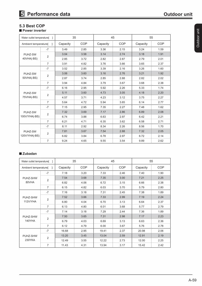
Performance data5 Outdoor unit
5.3 Best COPPower inverter
Zubadan
Water outlet temperature[ ] 35 45 55
Ambient temperature[ ] Capacity COP Capacity COP Capacity COP
PUHZ-SW
40VHA(-BS)
-7 3.49 2.85 3.36 2.15 3.24 1.59
23.04 3.58 3.14 2.74 3.18 1.91
2.85 3.72 2.82 2.87 2.79 2.01
7 3.91 4.82 3.76 3.66 3.65 2.37
PUHZ-SW
50VHA(-BS)
-7 3.52 2.85 3.39 2.16 3.26 1.60
23.06 3.60 3.16 2.76 3.21 1.92
2.87 3.74 2.85 2.88 2.82 2.02
7 3.94 4.84 3.79 3.67 3.68 2.38
PUHZ-SW
75VHA(-BS)
-7 6.16 2.95 5.92 2.26 5.33 1.74
25.11 3.60 4.73 3.05 4.18 2.20
4.57 3.71 4.23 3.12 3.75 2.27
7 5.64 4.72 5.94 3.65 6.14 2.77
PUHZ-SW
100V/YHA(-BS)
-7 7.15 2.95 7.35 2.27 7.48 1.62
27.32 3.69 7.17 2.86 6.89 2.08
6.74 3.88 6.63 2.97 6.42 2.21
7 6.21 4.71 6.35 3.62 6.58 2.71
PUHZ-SW
120V/YHA(-BS)
-7 8.11 2.92 8.34 2.26 8.56 1.70
27.81 3.67 7.54 2.88 7.32 2.05
6.82 3.84 6.78 2.97 6.72 2.14
7 9.24 4.65 9.55 3.54 9.89 2.62
Water outlet temperature[ ] 35 45 55
Ambient temperature[ ] Capacity COP Capacity COP Capacity COP
PUHZ-SHW
80VHA
-7 7.18 3.20 7.33 2.46 7.40 1.90
27.54 3.68 7.35 3.00 7.21 2.25
6.82 4.06 6.72 3.15 6.66 2.38
7 6.15 4.82 6.03 3.70 5.79 2.80
PUHZ-SHW
112V/YHA
-7 7.16 3.18 7.31 2.45 7.38 1.89
27.52 3.66 7.33 2.99 7.19 2.24
6.80 4.04 6.70 3.13 6.64 2.37
7 6.13 4.80 6.01 3.68 5.77 2.79
PUHZ-SHW
140YHA
-7 7.14 3.18 7.29 2.44 7.36 1.89
27.50 3.65 7.31 2.98 7.17 2.23
6.79 4.03 6.69 3.13 6.63 2.36
7 6.12 4.79 6.00 3.67 5.76 2.78
PUHZ-SHW
230YKA
-7 16.68 2.95 19.41 2.37 20.98 2.06
213.20 3.45 13.04 2.59 12.91 2.19
12.49 3.55 12.22 2.73 12.00 2.25
7 11.43 4.31 13.94 3.17 15.42 2.42
A-63
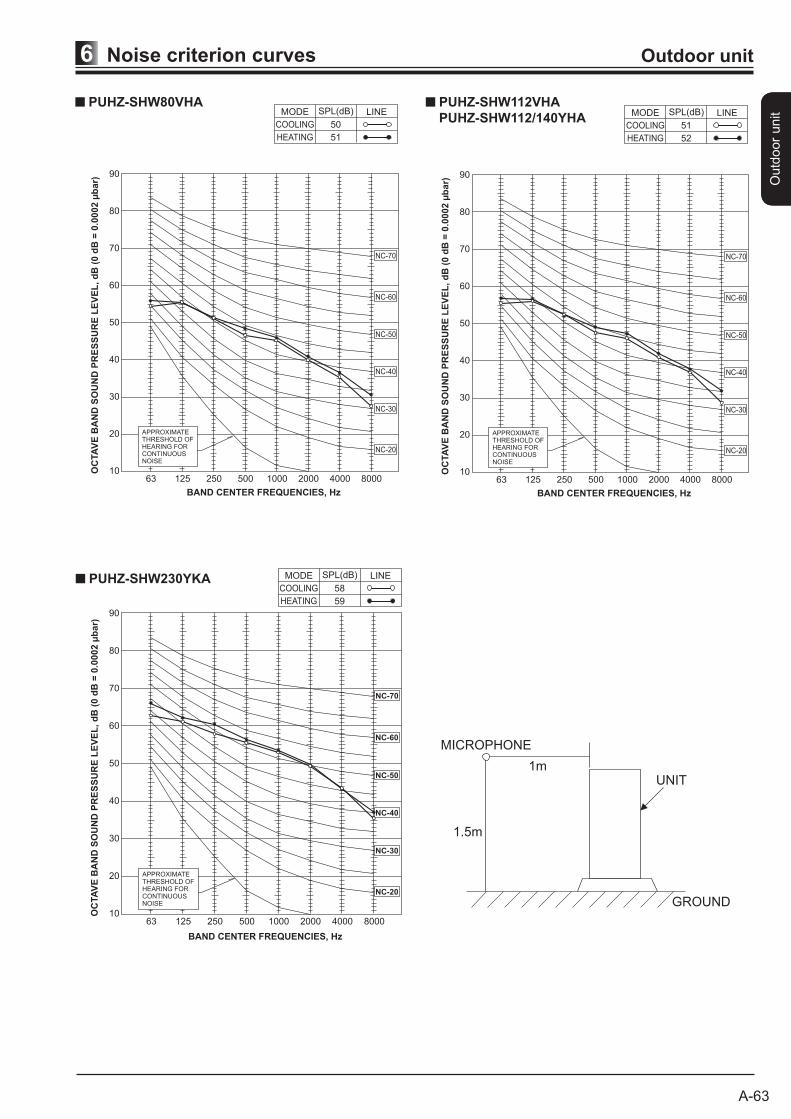
Noise criterion curves6 Outdoor unit
Outd
oor
unit
MICROPHONE
NC-60
NC-50
NC-40
NC-30
NC-20
NC-70
90
80
70
60
50
40
30
20
10OC
TA
VE
BA
ND
SO
UN
D P
RE
SS
UR
E L
EV
EL
, d
B (
0 d
B =
0.0
002 µ
bar)
63 125 250 500 1000 2000 4000 8000
APPROXIMATETHRESHOLD OFHEARING FORCONTINUOUSNOISE
BAND CENTER FREQUENCIES, Hz
COOLING
MODE
HEATING
50
SPL(dB)
51
LINEPUHZ-SHW80VHA
90
80
70
60
50
40
30
20
1063 125 250 500 1000 2000 4000 8000
APPROXIMATETHRESHOLD OFHEARING FORCONTINUOUSNOISE
OC
TA
VE
BA
ND
SO
UN
D P
RE
SS
UR
E L
EV
EL
, d
B (
0 d
B =
0.0
002 µ
bar)
BAND CENTER FREQUENCIES, Hz
NC-60
NC-50
NC-40
NC-30
NC-20
NC-70
PUHZ-SHW230YKACOOLING
MODE
HEATING
58
SPL(dB)
59
LINE
1.5m
1m
MICROPHONE
UNIT
GROUND
PUHZ-SHW230YKA
MICROPHONE
NC-60
NC-50
NC-40
NC-30
NC-20
NC-70
90
80
70
60
50
40
30
20
10OC
TA
VE
BA
ND
SO
UN
D P
RE
SS
UR
E L
EV
EL
, d
B (
0 d
B =
0.0
002 µ
bar)
63 125 250 500 1000 2000 4000 8000
APPROXIMATETHRESHOLD OFHEARING FORCONTINUOUSNOISE
BAND CENTER FREQUENCIES, Hz
COOLING
MODE
HEATING
51
SPL(dB)
52
LINEPUHZ-SHW112VHA
PUHZ-SHW112/140YHA
Outd
oor
unit
A-82
Installation location9 Outdoor unit
Outd
oor u
nit
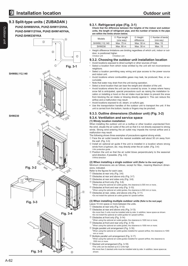
9.3.1. Refrigerant pipe (Fig. 3-1) Check that the difference between the heights of the indoor and outdoor
units, the length of refrigerant pipe, and the number of bends in the pipe
are within the limits shown below.
Models Pipe length
(one way)
Height
difference
Number of bends
(one way)
SHW80,112,140 Max. 75 m Max. 30 m Max. 15
SHW230 Max. 80 m Max. 30 m Max. 15
• Height difference limitations are binding regardless of which unit, indoor or out-
door, is positioned higher. Indoor unit Outdoor unit
Fig. 3-1
9.3.4. Ventilation and service space(1) Windy location installationWhen installing the outdoor unit on a rooftop or other location unprotected from
the wind, situate the air outlet of the unit so that it is not directly exposed to strong
winds. Strong wind entering the air outlet may impede the normal airflow and a
malfunction may result.
The following shows three examples of precautions against strong winds.
Face the air outlet towards the nearest available wall about 50 cm away from
the wall. (Fig. 3-3)
Install an optional air guide if the unit is installed in a location where strong
winds from a typhoon, etc. may directly enter the air outlet. (Fig. 3-4) Air protection guide
Position the unit so that the air outlet blows perpendicularly to the seasonal
wind direction, if possible. (Fig. 3-5) Wind direction
Fig. 3-4
Fig. 3-3
Fig. 3-5
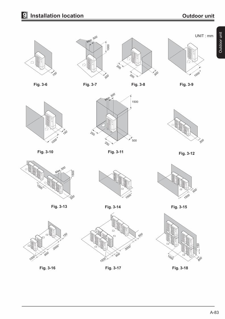
(2) When installing a single outdoor unit (Refer to the next page)
Minimum dimensions are as follows, except for Max., meaning Maximum dimen-
sions, indicated.
Refer to the figures for each case.
Obstacles at rear only (Fig. 3-6)
Obstacles at rear and above only (Fig. 3-7)
Obstacles at rear and sides only (Fig. 3-8)
Obstacles at front only (Fig. 3-9) *When using the optional air outlet guides, the clearance is 500 mm or more.
Obstacles at front and rear only (Fig. 3-10) *When using the optional air outlet guides, the clearance is 500 mm or more.
Obstacles at rear, sides, and above only (Fig. 3-11) •Do not install the optional air outlet guides for upward airflow.
(3) When installing multiple outdoor units (Refer to the next page)
Leave 10 mm space or more between the units.
Obstacles at rear only (Fig. 3-12)
Obstacles at rear and above only (Fig. 3-13) •No more than 3 units must be installed side by side. In addition, leave space as shown.
•Do not install the optional air outlet guides for upward airflow.
Obstacles at front only (Fig. 3-14) *When using the optional air outlet guides, the clearance is 1000 mm or more.
Obstacles at front and rear only (Fig. 3-15) *When using the optional air outlet guides, the clearance is 1000 mm or more.
Single parallel unit arrangement (Fig. 3-16) * When using the optional air outlet guides installed for upward airflow, the clearance is 1000
mm or more.
Multiple parallel unit arrangement (Fig. 3-17) * When using the optional air outlet guides installed for upward airflow, the clearance is
1500 mm or more.
Stacked unit arrangement (Fig. 3-18) •The units can be stacked up to 2 units high.
• No more than 2 stacked units must be installed side by side. In addition, leave space as
shown.
9.3.2. Choosing the outdoor unit installation location• Avoid locations exposed to direct sunlight or other sources of heat.
• Select a location from which noise emitted by the unit will not inconvenience
neighbors.
• Select a location permitting easy wiring and pipe access to the power source
and indoor unit.
• Avoid locations where combustible gases may leak, be produced, flow, or ac-
cumulate.
• Note that water may drain from the unit during operation.
• Select a level location that can bear the weight and vibration of the unit.
• Avoid locations where the unit can be covered by snow. In areas where heavy
snow fall is anticipated, special precautions such as raising the installation lo-
cation or installing a hood on the air intake must be taken to prevent the snow
from blocking the air intake or blowing directly against it. This can reduce the
airflow and a malfunction may result.
• Avoid locations exposed to oil, steam, or sulfuric gas.
• Use the transportation handles of the outdoor unit to transport the unit. If the
unit is carried from the bottom, hands or fingers may be pinched.
9.3.3. Outline dimensions (Outdoor unit) (Fig. 3-2)
Fig. 3-2
SHW230
1050
330+25
13
38
225
600
370
SHW80,112,140
950
330+30
13
50
175600
370
9.3 Split-type units ( ZUBADAN )
PUHZ-SHW80VHA, PUHZ-SHW112VHA,
PUHZ-SHW112YHA, PUHZ-SHW140YHA,
PUHZ-SHW230YKA
A-83
Installation location9 Outdoor unit
Outd
oor
unit
Fig. 3-7
Fig. 3-11 Fig. 3-12
Fig. 3-13 Fig. 3-14 Fig. 3-15
Fig. 3-16 Fig. 3-17 Fig. 3-18
Fig. 3-10
Fig. 3-9Fig. 3-8Fig. 3-6
150
300
1000
Max. 500
200
300200 1000
150
1000
250
250
1500
500
Max. 500
300
1500
500
1500
Max. 300
15001500
500
1000600
2000
150
1500600
3000
500
150080
0
150
UNIT : mm