
Daniel Söderberg KTH Royal Institute of Technology€¦ · Daniel Söderberg KTH Royal Institute...
24
Beating nature – the worlds strongest bio-material ever Daniel Söderberg KTH Royal Institute of Technology
Transcript of Daniel Söderberg KTH Royal Institute of Technology€¦ · Daniel Söderberg KTH Royal Institute...
Beating nature – the worlds strongest bio-material ever
Daniel Söderberg
KTH Royal Institute of Technology
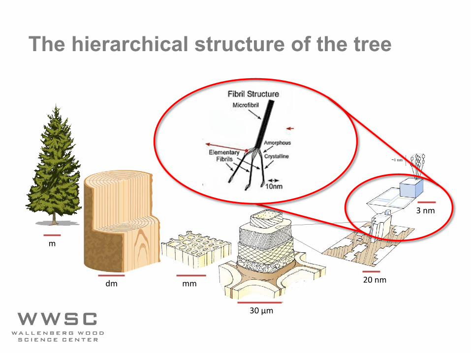
The hierarchical structure of the tree
~ 30 μm
~ 20 nm
~5 nm
~1 nm
~ mm~ dm
~ mm
dm mm
30 µm
20 nm
3 nm
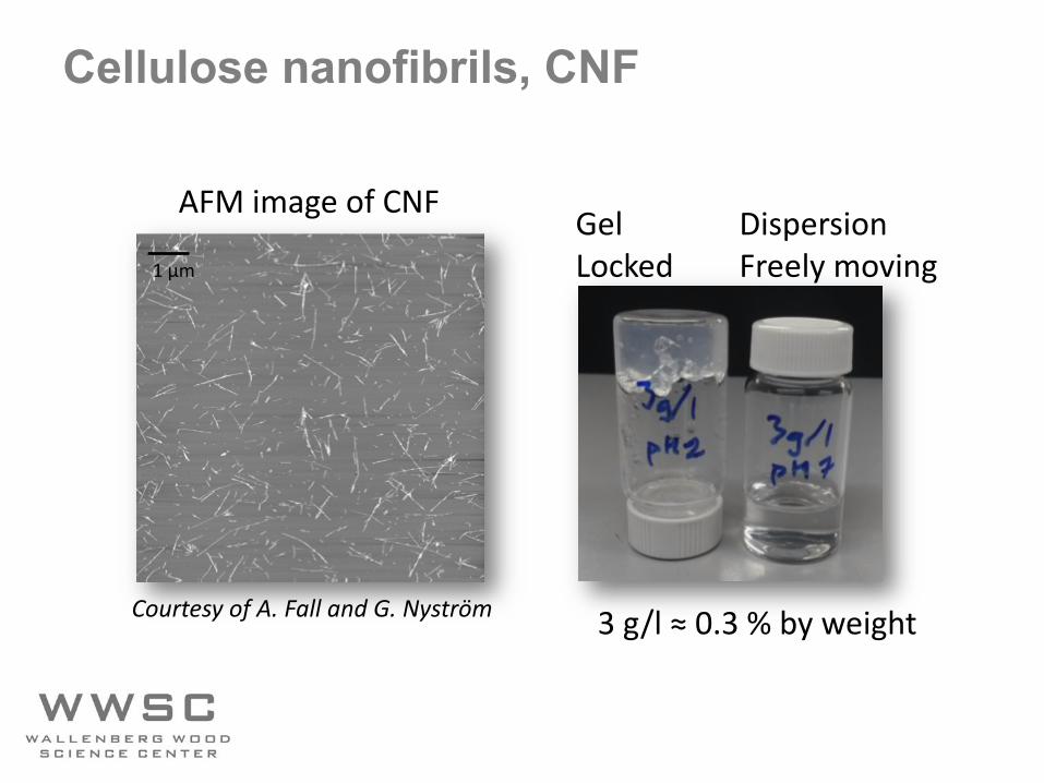
Cellulose nanofibrils, CNF
3 g/l ≈ 0.3 % by weight
AFM image of CNF GelLocked
DispersionFreely moving
Courtesy of A. Fall and G. Nyström
1 μm

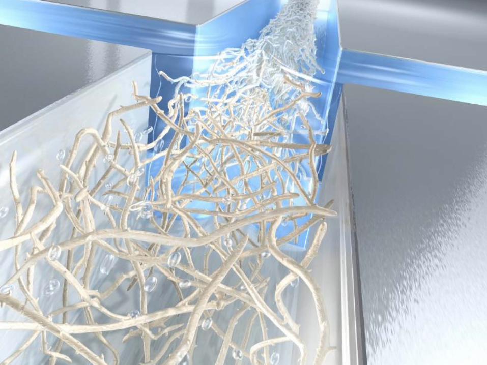
Wet spinning of cellulose nanofibrils
Walther el al. (2011) Adv. Mater.
b)
z
x
y
Q1
Q2/2
Q2/2
1
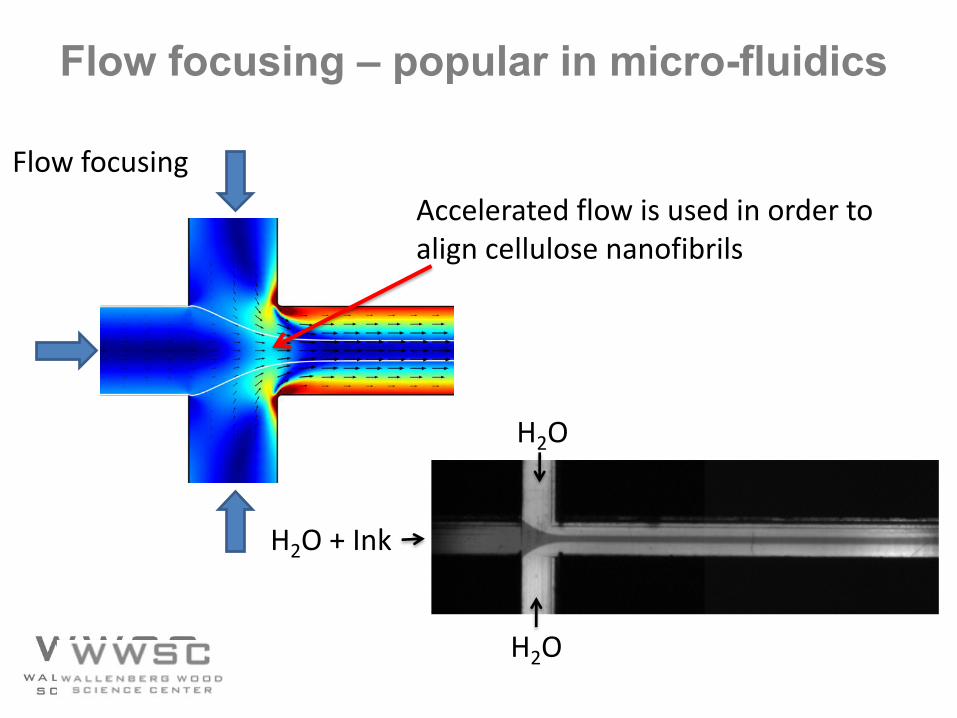
Flow focusing – popular in micro-fluidics
H2O
Flow focusing
h = 1 mm
H2O
H2O + Ink
H2O
Accelerated flow is used in order to align cellulose nanofibrils
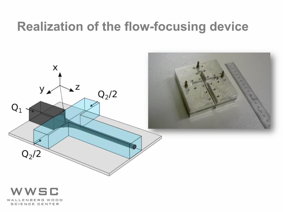
Realization of the flow-focusing device
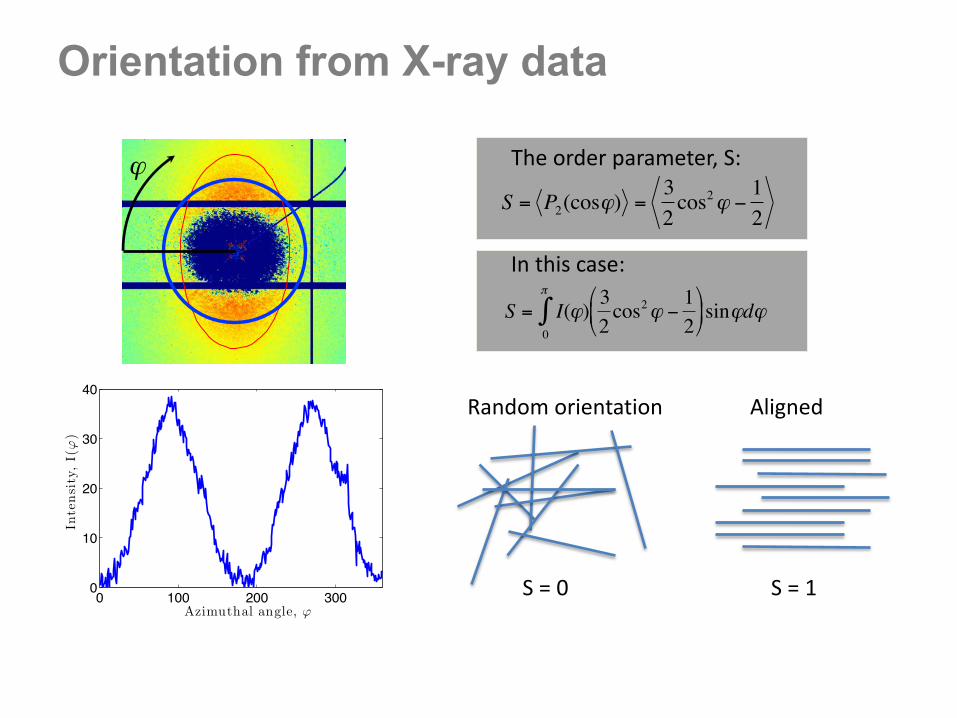
0 100 200 3000
10
20
30
40
Azimuthal angle, ϕ
Inte
nsi
ty,
I(ϕ
)Orientation from X-ray data
€
ϕ
Random orientation Aligned
S = 1S = 0
The order parameter, S:
€
S = P2(cosϕ) =32cos2ϕ −
12
€
S = I(ϕ)32cos2ϕ −
12
$
% &
'
( ) sinϕdϕ
0
π
∫
In this case:
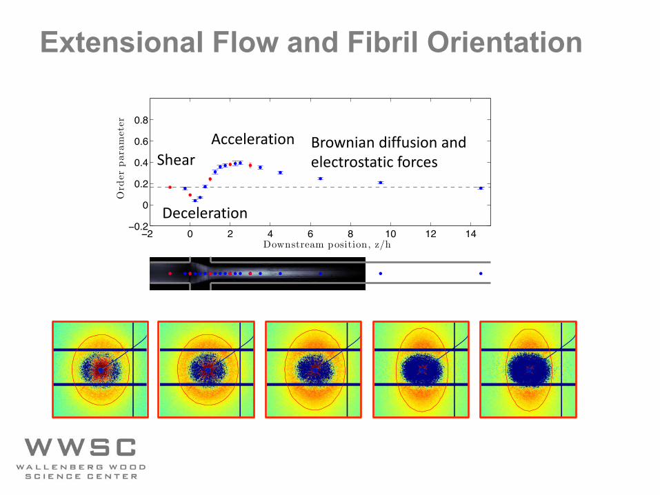
Extensional Flow and Fibril Orientation
−2 0 2 4 6 8 10 12 14−0.2
0
0.2
0.4
0.6
0.8
Downstream position, z/h
Ord
erpar
amet
er
Shear
Deceleration
Acceleration Brownian diffusion andelectrostatic forces
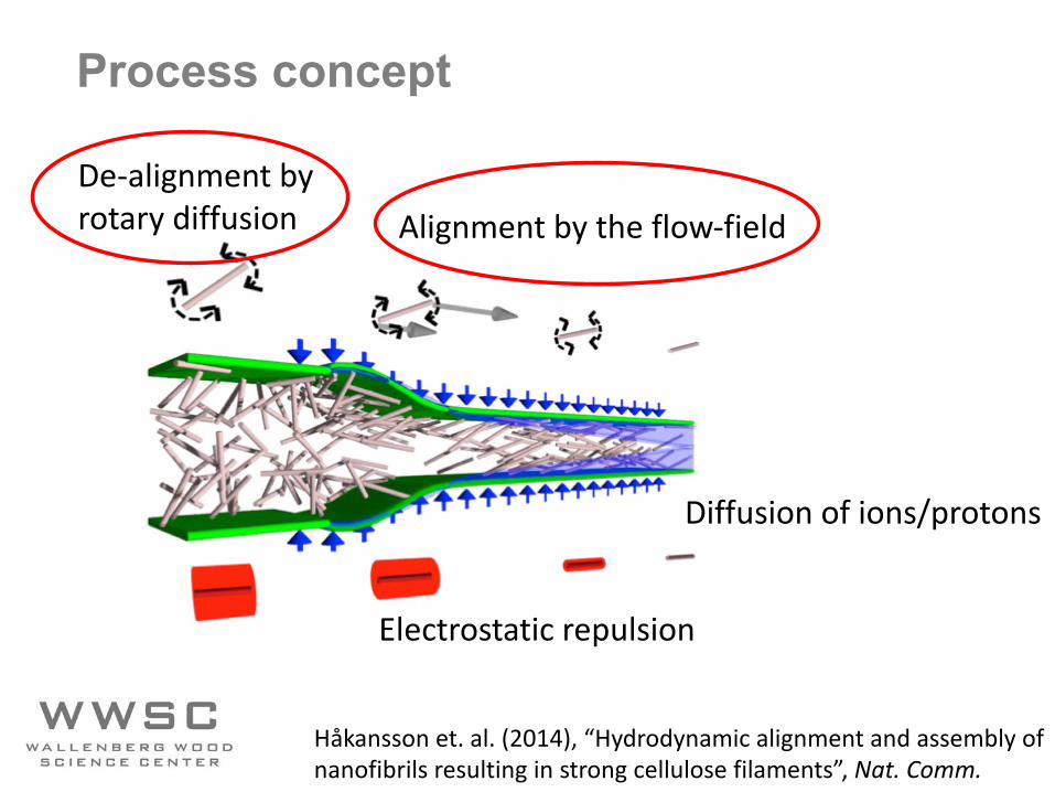
Process concept
Alignment by the flow-field
Electrostatic repulsion
Diffusion of ions/protons
De-alignment byrotary diffusion
Håkansson et. al. (2014), “Hydrodynamic alignment and assembly of nanofibrils resulting in strong cellulose filaments”, Nat. Comm.
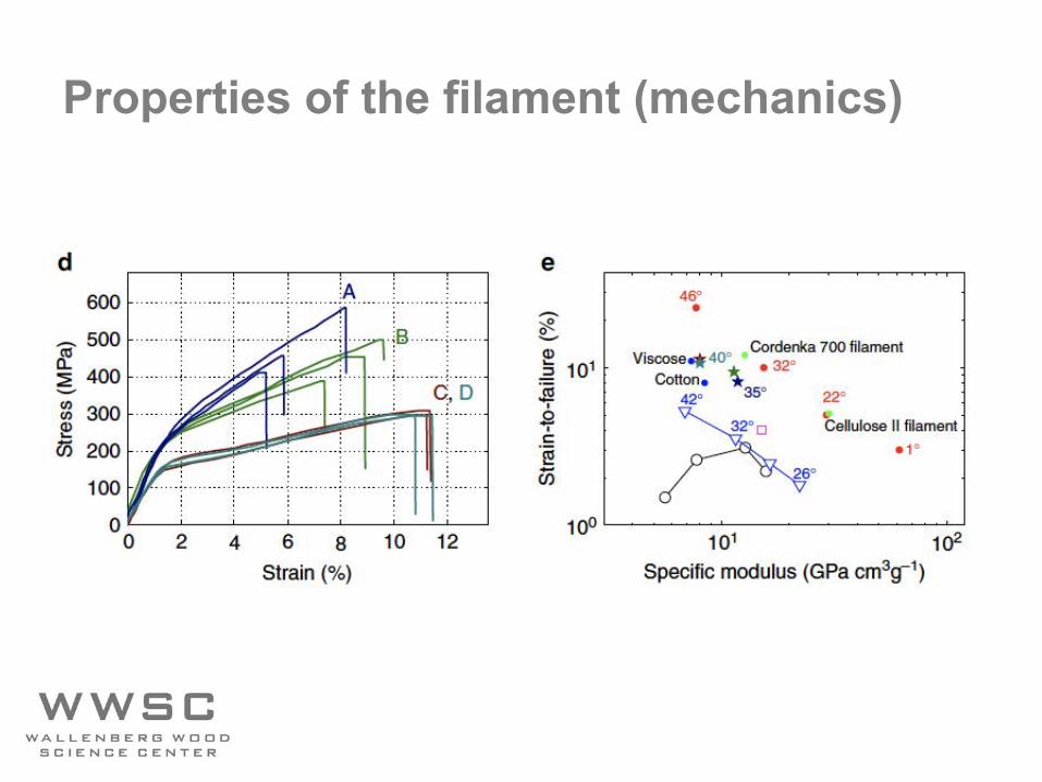
Properties of the filament (mechanics)
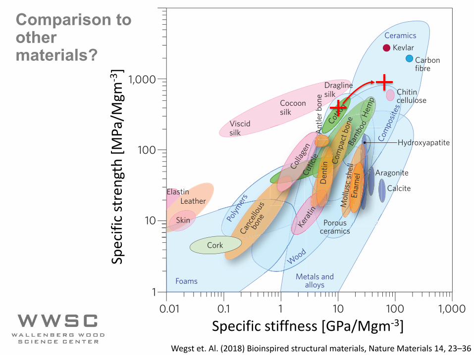
Wegst et. Al. (2018) Bioinspired structural materials, Nature Materials 14, 23–36
26 NATURE MATERIALS | VOL 14 | JANUARY 2015 | www.nature.com/naturematerials
example, if we consider bone and nacre, both of which comprise rather meagre constituents in terms of their mechanical properties, the resulting natural composites display far superior properties (as exemplified by their fracture toughness in Fig. 1b) that defeat the rule of mixtures. However, a pertinent question is whether we can emulate such designs and meet the greater challenge of making syn-thetic materials with such form and function.
One useful and frequently applied approach is that of materials design guided by first-principles calculations, which are based on an understanding of the different atomic components and the diverse sets of functional requirements. However, this strategy faces many issues. Despite decades of research, it has generally failed to yield significantly improved structural materials and performance, nor has it improved predictions of complex mechanical proper-ties such as toughness10. One reason for this failure is that current computational capabilities and tools are insufficient to be able to integrate into one model physical mechanisms that act at multiple length scales and that affect a material’s mechanical performance. Moreover, some natural materials, such as bone, have the capacity for healing, self-repair and adaptation to changes in mechanical usage patterns, which poses an even greater challenge for the engi-neering of materials that mimic natural structures.
Bone and nacre. As described in several recent review articles11–15, bone and nacre (abalone shell) are prime examples of natural mate-rials that combine strength with toughness, making them truly damage-tolerant. Also described in this subsection are other natural materials that have evolved efficient strategies for developing excep-tional damage tolerance, including teeth, the dactyl clubs of stoma-topod shrimps16 , and bamboo17 .
Bone is composed of cells embedded in an extracellular matrix, which is an ordered network assembled from two major nanophases: collagen fibrils made from type-I collagen molecules (~300 nm long, ~1.5 nm in diameter) and hydroxyapatite (Ca10(PO4)6(OH)2)) nanocrystals (plate-shaped, 50 nm × 25 nm in size, 1.5–4 nm thick) distributed along the collagen fibrils18,19 (Fig. 2a). The hydroxyapa-tite nanocrystals are preferentially oriented with their c axis parallel to the collagen fibrils, and arranged in a periodic, staggered array along the fibrils18,19. These two nanophases make up about 95% of the dry weight of bone18. The structures form a tough yet light-weight, adaptive, self-healing and multifunctional material. Bone derives its resistance to fracture with a multitude of deformation and toughening mechanisms operating at many size scales, ranging from the nanoscale structure of its protein molecules to the macro-scopic physiological scale12.
The origins of fracture resistance in healthy human cortical bone can be conveniently separated into intrinsic mechanisms that pro-mote ductility and extrinsic mechanisms that act to ‘shield’ a growing crack12 (Fig. 3). Intrinsic toughening mechanisms result primarily from plasticity (Box 1). In bone, they originate from mechanisms at work at the smallest length scales, including molecular uncoiling of the mineralized collagen components and, most importantly, the process of fibrillar sliding. As load is applied, it is carried as tension in the mineral platelets and transferred between the platelets via shearing of the collagenous matrix20. This fibrillar sliding mecha-nism is essential to promote plasticity at this length scale. Many aspects of the collagen fibril’s structure, such as the hydroxyapatite/collagen interface, intermolecular crosslinking and sacrificial bond-ing21, play a role in its ability to promote fibrillar sliding efficiently. These features constrain molecular stretching and provide the basis
Leather
Skin
Elastin
Cocoonsilk
Viscidsilk
Draglinesilk Chitin
cellulose
Bam
booCot
ton
Ant
ler b
one
Collag
enCu
ticle
Kerat
in
Calcite
Aragonite
Hydroxyapatite
Enam
el
Mol
lusc
shel
l
Den
tinCo
mpa
ct b
one
Ceramics
0.01 0.1 1 10 100 1,0001
10
100
Specific stiffness (GPa/(Mg m–3))
Spec
ific
stre
ngth
(MPa
/(M
g m
–3)) 1,000
Com
posit
es
KevlarCarbonfibre
Porousceramics
ooooHe
mp
Foams Metals andalloys
Polym
ers
Wood
Young’s modulus (GPa)
0.1 10 1,0001 100
10
1
0.1
0.01
Frac
ture
toug
hnes
s (M
Pa m
½)
100
Nacre protein
Nacre
Aragonite
Bone
Hydroxyapatite
Alumina/PMMA
Alumina
Future composites
Collagen
PMMA
Rule of mixtures
a b
Cance
llous
bone
Cork
Figure 1 | Material-property chart, and projections for natural and synthetic materials. a, Ashby plot4 of the specific values (that is, normalized by density) of strength and stiffness (or Young’s modulus) for both natural and synthetic materials. Many engineering materials, particularly high-performance ceramics and metallic alloys, have values of strength and toughness that are much higher than those of the best natural materials. Silk stands out as an exception, sometimes reaching the extraordinary toughness of 1,000 MJ m–3 with a modulus of 10 GPa (ref. 122) — approaching that of Kevlar. One might therefore conclude that there is nothing spectacular about the properties of natural materials, as in general they seem similar to what can be made synthetically. However, quite unlike most synthetic materials, all natural structural materials use a limited chemical palette of inexpensive ingredients — typically, proteins, polysaccharides, calcites and aragonites, and rarely metals — whose properties are often meagre, and are formed at ambient temperatures with little energy requirements. Moreover, the constituents of natural materials are typically arranged in a hierarchical architecture of interwoven or interlocking structures that is difficult to reproduce synthetically. Many natural materials also repair themselves when damaged; in contrast, self-healing synthetic structures are still highly limited. b, Many natural composite materials, as exemplified by bone and nacre, have toughness values that far exceed those of their constituents and their homogeneous mixtures (as indicated by the dashed lines), and are able to sustain incipient cracking by utilizing extensive extrinsic toughening mechanisms (Figs 3 and 4b). This results in much higher toughness for crack growth (closed symbols above the solid arrows) than for crack initiation (open symbols), and thus higher fracture toughness (solid arrows). By mimicking the architecture of nacre in a synthetic ceramic material (alumina/PMMA)85, similar behaviour and exceptional toughness can be attained.
REVIEW ARTICLE NATURE MATERIALS DOI: 10.1038/NMAT4089
© 2014 Macmillan Publishers Limited. All rights reserved
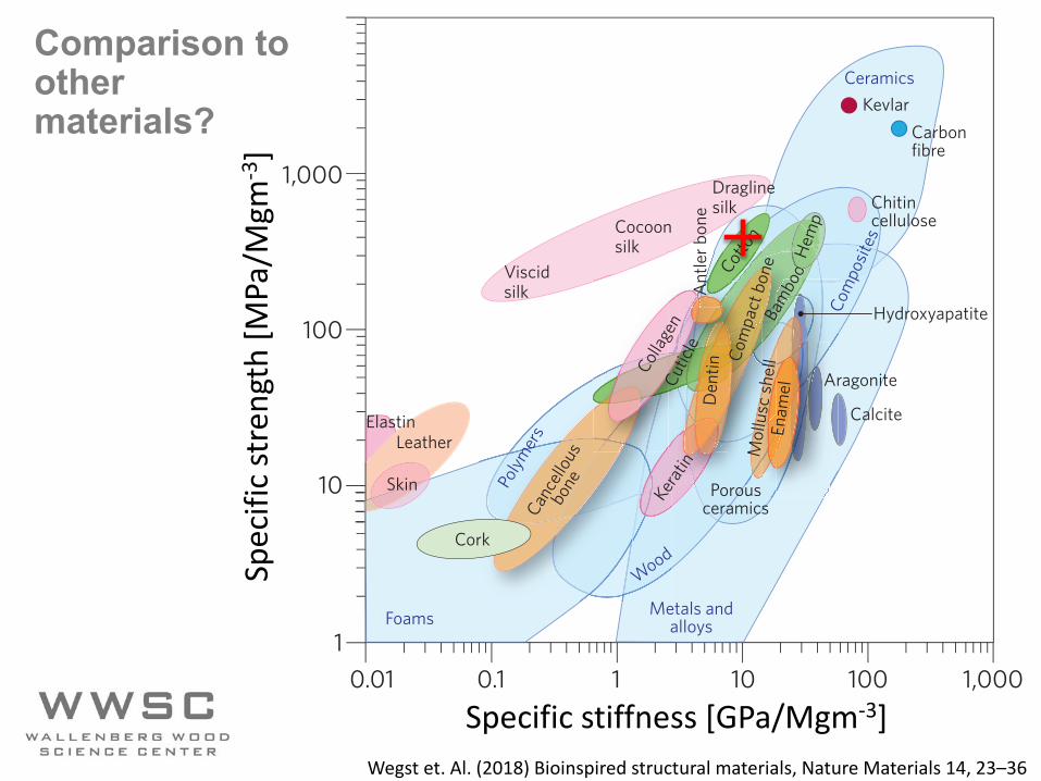
Comparison to othermaterials?
Sp
eci
fic
stre
ngt
h[M
Pa
/Mg
m-3
]
Specific stiffness [GPa/Mgm-3]
5 µm
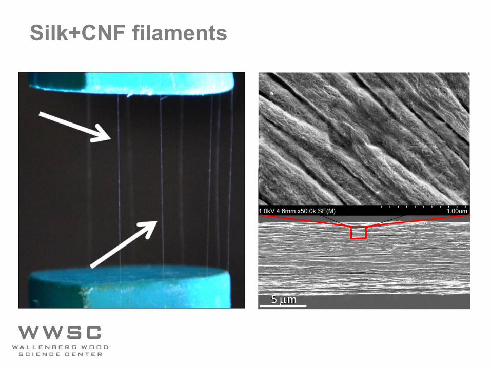
Silk+CNF filaments
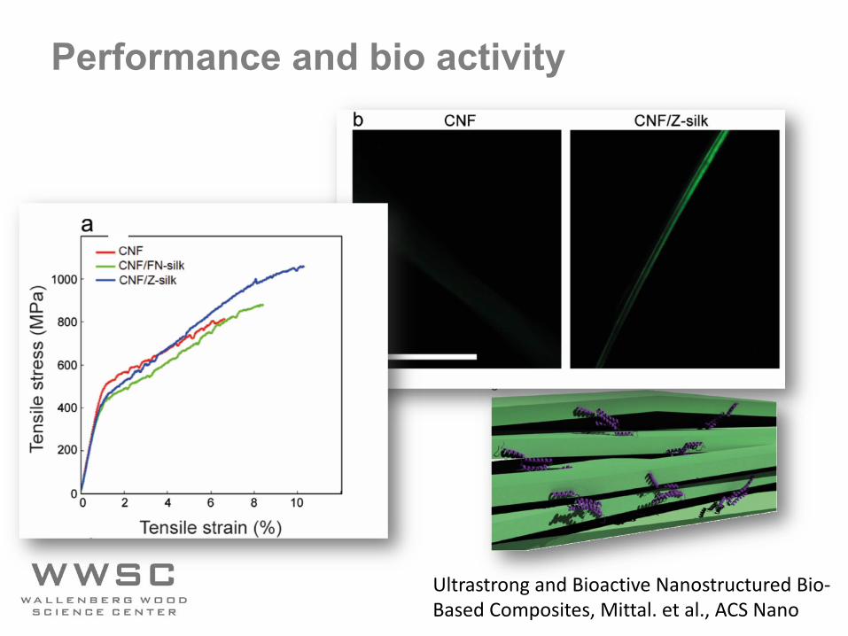
Performance and bio activity
Ultrastrong and Bioactive Nanostructured Bio-Based Composites, Mittal. et al., ACS Nano
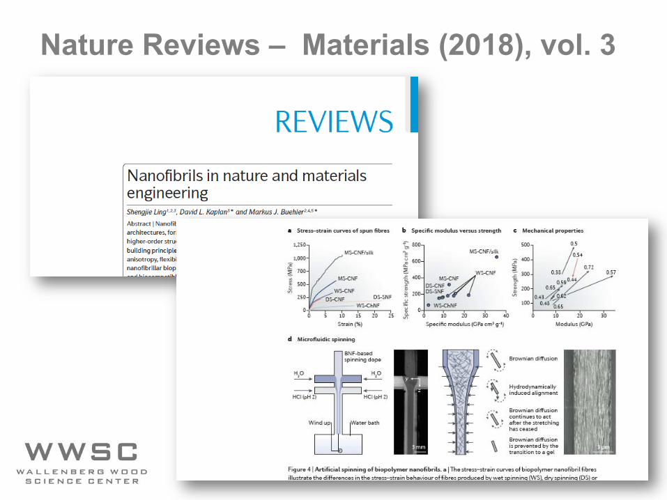
Nature Reviews – Materials (2018), vol. 3
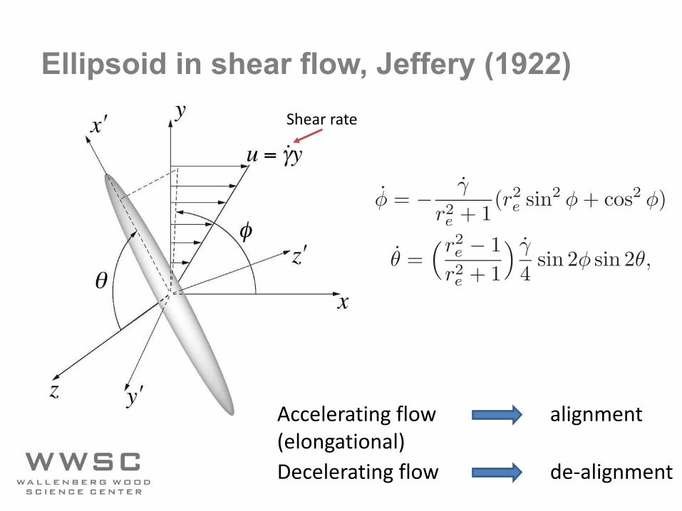
Ellipsoid in shear flow, Jeffery (1922)Shear rate
6 2. ROD-LIKE PARTICLES IN SHEAR FLOW
flow, characteristic velocity and length scale, respectively. For steady flowswhere the inertial effects are negligible as compared to effects of viscosity, i.e.Re << 1, equation (2.1) is approximately reduced to
1
ρ∇p = ν∇2u + f . (2.3)
Flows that are described by equation (2.3) are generally called Stokes flows.
2.2. Unbounded shear flow
2.2.1. Single particles
The motion of a solid ellipsoid, with a surface defined by x′2/a2 + y′2/b2 +z′2/c2 = 1, suspended in a simple shear flow, was computed analytically byJeffery (1922). For the case where b = c, i.e a spheroid, the solutions are
φ̇ = −γ̇
r2e + 1
(r2e sin2 φ+ cos2 φ) (2.4)
θ̇ =!r2
e − 1
r2e + 1
" γ̇
4sin 2φ sin 2θ, (2.5)
where γ̇ is the shear rate and re = a/b is the ellipsoidal aspect ratio. Jeffery’sequations are valid for both prolate spheroids (re > 1) and oblate spheroids(re < 1), but since the main focus of this study concerns rod-like particles onlythe motion of prolate spheroids will be considered. For a simple shear, witha velocity defined by u = γ̇yex, the angle φ is taken from the flow directionx to the projection of the x′-axis in the xy-plane and θ is the angle from thevorticity axis z to x′. The coordinate system is illustrated in figure 2.1.
Equations (2.4) and (2.5) are valid for conditions in which the particleReynolds number ReL = (γ̇L2)/ν << 1, where L is typically a or b. Directlyfrom the equations it is seen that the angular velocities φ̇ and θ̇ depend linearlywith the shear rate. The spheroid will rotate in closed orbits with a period
T =2π
γ̇
!r2e + 1
re
"
. (2.6)
If equations (2.4) and (2.5) are integrated with respect to time they may berewritten to
cotφ = −re cot!2πt
T+ φ0
"
(2.7)
tan θ =Cre
(r2e sin2 φ+ cos2 φ)1/2
, (2.8)
where C is the orbit constant and φ0 is the initial value of φ. A numberof possible orbits are illustrated in figure 2.2, for re = 40. For C = 0 thespheroid is oriented with its major axis aligned with the vorticity axis and itrotates around this axis with a constant angular velocity γ̇/2. As C approachesinfinity the major axis of the spheroid will be located in the flow-gradient plane,
Accelerating flow alignment(elongational)Decelerating flow de-alignment
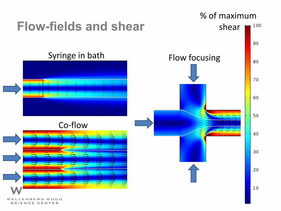
Flow-fields and shear
Syringe in bath
Co-flow
Flow focusing
% of maximum shear
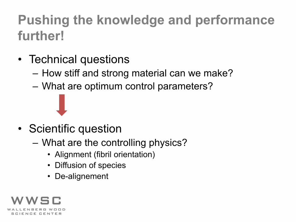
Pushing the knowledge and performancefurther!• Technical questions
– How stiff and strong material can we make?– What are optimum control parameters?
• Scientific question– What are the controlling physics?
• Alignment (fibril orientation)• Diffusion of species• De-alignement
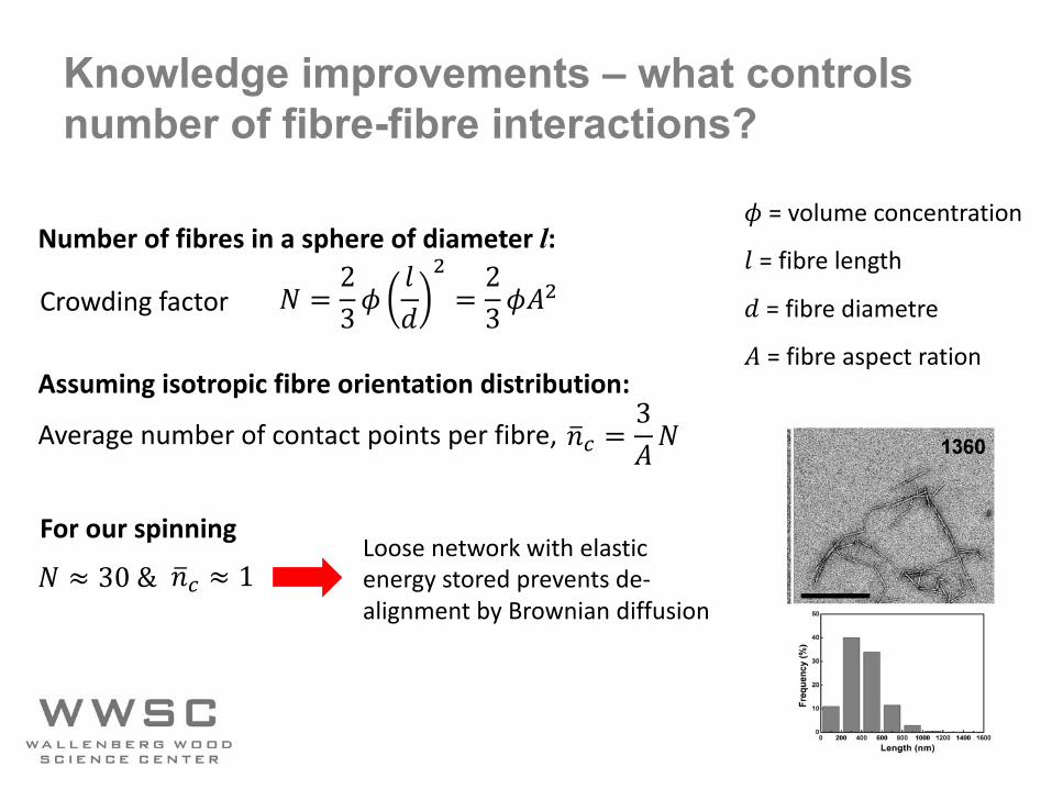
Knowledge improvements – what controls number of fibre-fibre interactions?
! = 23%
&'
(= 23%)
(
*+, =3)!
Assuming isotropic fibre orientation distribution:
Crowding factor
Average number of contact points per fibre,
Number of fibres in a sphere of diameter l: % = volume concentration
& = fibre length
' = fibre diametre
) = fibre aspect ration
*+, ≈ 1! ≈ 30 &For our spinning
Loose network with elastic energy stored prevents de-alignment by Brownian diffusion
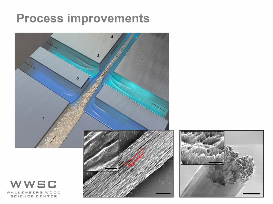
Process improvements
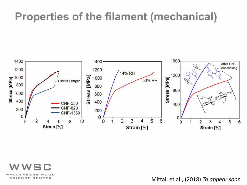
Properties of the filament (mechanical)
Mittal. et al., (2018) To appear soon
Wegst et. Al. (2018) Bioinspired structural materials, Nature Materials 14, 23–36
26 NATURE MATERIALS | VOL 14 | JANUARY 2015 | www.nature.com/naturematerials
example, if we consider bone and nacre, both of which comprise rather meagre constituents in terms of their mechanical properties, the resulting natural composites display far superior properties (as exemplified by their fracture toughness in Fig. 1b) that defeat the rule of mixtures. However, a pertinent question is whether we can emulate such designs and meet the greater challenge of making syn-thetic materials with such form and function.
One useful and frequently applied approach is that of materials design guided by first-principles calculations, which are based on an understanding of the different atomic components and the diverse sets of functional requirements. However, this strategy faces many issues. Despite decades of research, it has generally failed to yield significantly improved structural materials and performance, nor has it improved predictions of complex mechanical proper-ties such as toughness10. One reason for this failure is that current computational capabilities and tools are insufficient to be able to integrate into one model physical mechanisms that act at multiple length scales and that affect a material’s mechanical performance. Moreover, some natural materials, such as bone, have the capacity for healing, self-repair and adaptation to changes in mechanical usage patterns, which poses an even greater challenge for the engi-neering of materials that mimic natural structures.
Bone and nacre. As described in several recent review articles11–15, bone and nacre (abalone shell) are prime examples of natural mate-rials that combine strength with toughness, making them truly damage-tolerant. Also described in this subsection are other natural materials that have evolved efficient strategies for developing excep-tional damage tolerance, including teeth, the dactyl clubs of stoma-topod shrimps16 , and bamboo17 .
Bone is composed of cells embedded in an extracellular matrix, which is an ordered network assembled from two major nanophases: collagen fibrils made from type-I collagen molecules (~300 nm long, ~1.5 nm in diameter) and hydroxyapatite (Ca10(PO4)6(OH)2)) nanocrystals (plate-shaped, 50 nm × 25 nm in size, 1.5–4 nm thick) distributed along the collagen fibrils18,19 (Fig. 2a). The hydroxyapa-tite nanocrystals are preferentially oriented with their c axis parallel to the collagen fibrils, and arranged in a periodic, staggered array along the fibrils18,19. These two nanophases make up about 95% of the dry weight of bone18. The structures form a tough yet light-weight, adaptive, self-healing and multifunctional material. Bone derives its resistance to fracture with a multitude of deformation and toughening mechanisms operating at many size scales, ranging from the nanoscale structure of its protein molecules to the macro-scopic physiological scale12.
The origins of fracture resistance in healthy human cortical bone can be conveniently separated into intrinsic mechanisms that pro-mote ductility and extrinsic mechanisms that act to ‘shield’ a growing crack12 (Fig. 3). Intrinsic toughening mechanisms result primarily from plasticity (Box 1). In bone, they originate from mechanisms at work at the smallest length scales, including molecular uncoiling of the mineralized collagen components and, most importantly, the process of fibrillar sliding. As load is applied, it is carried as tension in the mineral platelets and transferred between the platelets via shearing of the collagenous matrix20. This fibrillar sliding mecha-nism is essential to promote plasticity at this length scale. Many aspects of the collagen fibril’s structure, such as the hydroxyapatite/collagen interface, intermolecular crosslinking and sacrificial bond-ing21, play a role in its ability to promote fibrillar sliding efficiently. These features constrain molecular stretching and provide the basis
Leather
Skin
Elastin
Cocoonsilk
Viscidsilk
Draglinesilk Chitin
cellulose
Bam
booCot
ton
Ant
ler b
one
Collag
enCu
ticle
Kerat
in
Calcite
Aragonite
Hydroxyapatite
Enam
el
Mol
lusc
shel
l
Den
tinCo
mpa
ct b
one
Ceramics
0.01 0.1 1 10 100 1,0001
10
100
Specific stiffness (GPa/(Mg m–3))
Spec
ific
stre
ngth
(MPa
/(M
g m
–3)) 1,000
Com
posit
es
KevlarCarbonfibre
Porousceramics
ooooHe
mp
Foams Metals andalloys
Polym
ers
Wood
Young’s modulus (GPa)
0.1 10 1,0001 100
10
1
0.1
0.01
Frac
ture
toug
hnes
s (M
Pa m
½)
100
Nacre protein
Nacre
Aragonite
Bone
Hydroxyapatite
Alumina/PMMA
Alumina
Future composites
Collagen
PMMA
Rule of mixtures
a b
Cance
llous
bone
Cork
Figure 1 | Material-property chart, and projections for natural and synthetic materials. a, Ashby plot4 of the specific values (that is, normalized by density) of strength and stiffness (or Young’s modulus) for both natural and synthetic materials. Many engineering materials, particularly high-performance ceramics and metallic alloys, have values of strength and toughness that are much higher than those of the best natural materials. Silk stands out as an exception, sometimes reaching the extraordinary toughness of 1,000 MJ m–3 with a modulus of 10 GPa (ref. 122) — approaching that of Kevlar. One might therefore conclude that there is nothing spectacular about the properties of natural materials, as in general they seem similar to what can be made synthetically. However, quite unlike most synthetic materials, all natural structural materials use a limited chemical palette of inexpensive ingredients — typically, proteins, polysaccharides, calcites and aragonites, and rarely metals — whose properties are often meagre, and are formed at ambient temperatures with little energy requirements. Moreover, the constituents of natural materials are typically arranged in a hierarchical architecture of interwoven or interlocking structures that is difficult to reproduce synthetically. Many natural materials also repair themselves when damaged; in contrast, self-healing synthetic structures are still highly limited. b, Many natural composite materials, as exemplified by bone and nacre, have toughness values that far exceed those of their constituents and their homogeneous mixtures (as indicated by the dashed lines), and are able to sustain incipient cracking by utilizing extensive extrinsic toughening mechanisms (Figs 3 and 4b). This results in much higher toughness for crack growth (closed symbols above the solid arrows) than for crack initiation (open symbols), and thus higher fracture toughness (solid arrows). By mimicking the architecture of nacre in a synthetic ceramic material (alumina/PMMA)85, similar behaviour and exceptional toughness can be attained.
REVIEW ARTICLE NATURE MATERIALS DOI: 10.1038/NMAT4089
© 2014 Macmillan Publishers Limited. All rights reserved
Comparison to othermaterials?
Sp
eci
fic
stre
ngt
h[M
Pa
/Mg
m-3
]
Specific stiffness [GPa/Mgm-3]
Thank You and Thanks to:
KTH Mechanics:PhD. D. SöderbergAssoc. Prof. F. LundellPhD. C. BrouzetMSc. N. Mittal
Innventia AB:PhD. T. LarssonPhD. C. HolmqvistPhD. K Håkansson
SBUProf. B. HsiaoPhD. T. Rosén
Kungliga Tekniska Högskolan (KTH)Deutsches Elektronen-Synchrotron (DESY)Wallenberg Wood Science Center (WWSC)University of Michigan, Ann Arbor (UMICH)Stony Brook University (SBU)Linné FLOW CentreRISE Bioeconomy
DESY Hamburg:Prof. S. V. RothPhD. C. Krywka
KTH School of Engineering Science in Biotechnology, Chemistry and HealthProf. L. WågbergAssoc. Prof. M HedhammarPhD. C. LendelPhD. R JanssonPhD. Mona Widhe
UMICHProf. N. Kotov