Cylinder with Lock - smcpneumatics.com the load mass m = 320 kg ... 3-wire (NPN equivalent) 24 V 24...
23
Series CNS Cylinder with Lock ø125, ø140, ø160 A locking cylinder ideal for intermediate stops, emergency stops and drop prevention. 125 140 160 Series Variations 8.4 10.5 13.8 757 Simple construction A force magnifying mechanism is employed based on the wedge effect of the taper ring and steel balls. Taper ring Steel ball P R R θ f A metal rod scraper Standard equipment Resistance against welding process spatter and other external contaminants is achieved by providing a metal rod scraper as standard. Manual override for unlocking for emergency Even if the air supply is blocked or exhausted, lock release is possible. The fail safe mechanism locks again when the manual override is released. Design minimizes the influences of unlocking air quality A construction which is strong against moisture and drainage in the compressed air has been realized by separating the locking mechanism and the unlocking chamber. Can be locked in both directions All equal holding force can be obtained on either reciprocating stroke of the cylinder. High locking efficiency Greater locking efficiency as well as stable locking and unlocking operation has been achieved by arranging a large number of steel ball bearings in circular rows. (Unlocking pressure of 0.25 MPa ······ 0.05 MPa lower than conventional SMC products) In addition, both alignability and stable locking force with respect to piston rod eccentricity are obtained by allowing the taper ring to float. High reliability and stable holding force Outstanding durability and stable holding force are maintained by the use of a brake shoe having superior wear resistance, which has also been substantially lengthened (double the conventional SMC product). Standard variations With rod boot Type Action Standard stroke (mm) Series Single rod Series CNS Double acting Cylinder with lock Series CNS Maximum 1600 Lock holding force (kN) Bore size (mm) CLJ2 CLM2 CLG1 CL1 MLGC CNG MNB CNA CNS CLS CLQ RLQ MLU MLGP ML1C Individual -X D- -X
Transcript of Cylinder with Lock - smcpneumatics.com the load mass m = 320 kg ... 3-wire (NPN equivalent) 24 V 24...
Series CNSCylinder with Lock
ø125, ø140, ø160
A locking cylinder ideal for intermediate stops, emergency stops and drop prevention.
125140160
� Series Variations
8.4
10.5
13.8
757
Simple constructionA force magnifying mechanism is employed based on the wedge effect of the taper ring and steel balls.
Taper ringSteel ball
P
R R
θf
A metal rod scraper Standard equipmentResistance against welding process spatter and other external contaminants is achieved by providing a metal rod scraper as standard.
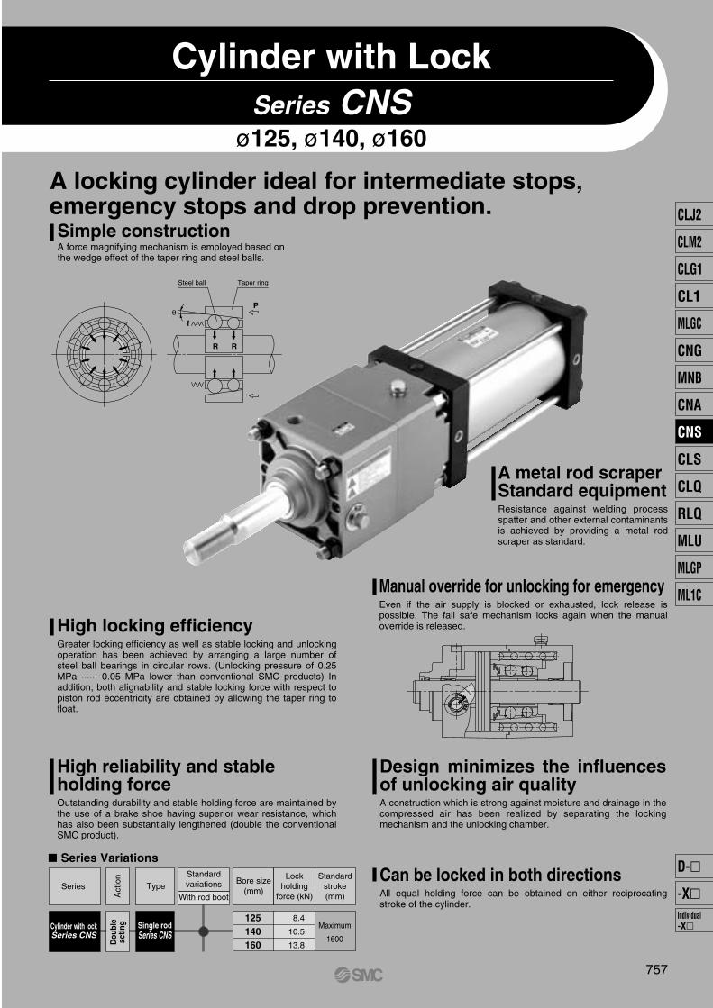
Manual override for unlocking for emergencyEven if the air supply is blocked or exhausted, lock release is possible. The fail safe mechanism locks again when the manual override is released.
Design minimizes the influences of unlocking air qualityA construction which is strong against moisture and drainage in the compressed air has been realized by separating the locking mechanism and the unlocking chamber.
Can be locked in both directionsAll equal holding force can be obtained on either reciprocating stroke of the cylinder.
High locking efficiencyGreater locking efficiency as well as stable locking and unlocking operation has been achieved by arranging a large number of steel ball bearings in circular rows. (Unlocking pressure of 0.25 MPa ······ 0.05 MPa lower than conventional SMC products) In addition, both alignability and stable locking force with respect to piston rod eccentricity are obtained by allowing the taper ring to float.
High reliability and stable holding forceOutstanding durability and stable holding force are maintained by the use of a brake shoe having superior wear resistance, which has also been substantially lengthened (double the conventional SMC product).
Standardvariations
With rod bootType
Act
ion Standard
stroke(mm)
Series
Single rodSeries CNS
Dou
ble
actin
gCylinder with lockSeries CNS
Maximum
1600
Lockholding
force (kN)
Bore size(mm)
CLJ2
CLM2
CLG1
CL1
MLGC
CNG
MNB
CNA
CNS
CLS
CLQ
RLQ
MLU
MLGP
ML1C
Individual-X�
D-�
-X�
P0757-P0838-E.qxd 08.11.17 3:04 PM Page 757
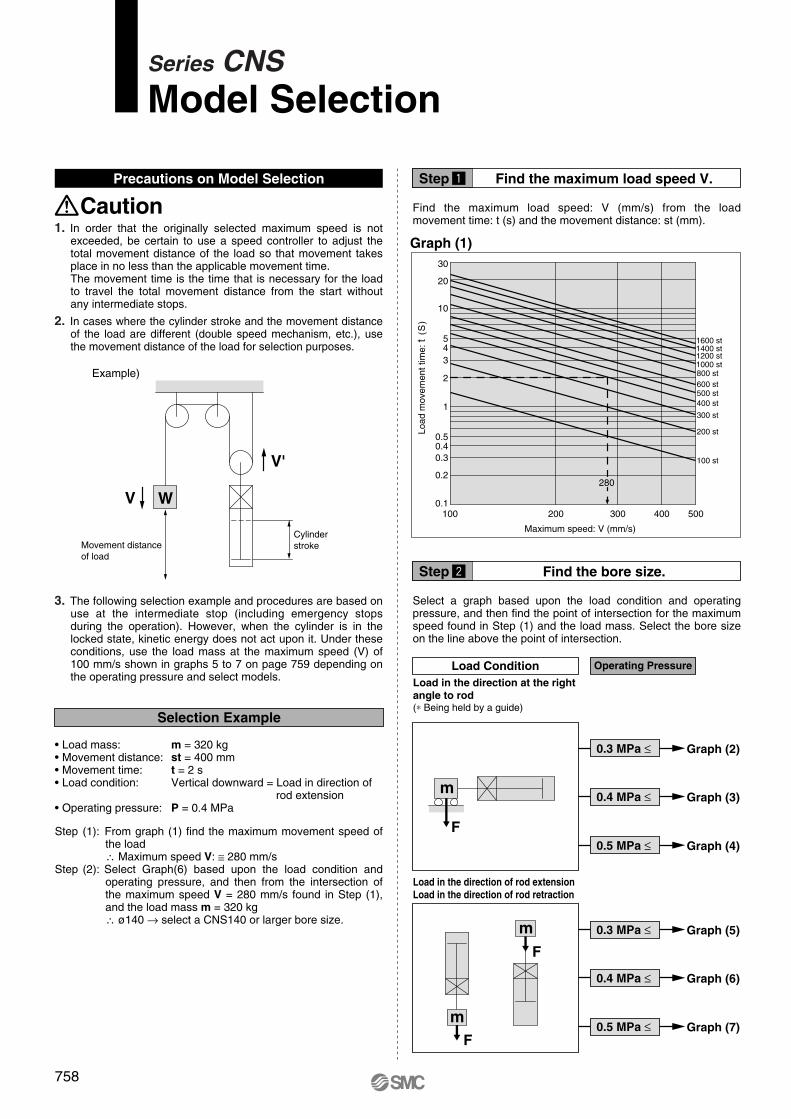
Find the maximum load speed V.
Selection Example
Graph (1)
V'
V W
30
1600 st1400 st1200 st1000 st800 st600 st500 st400 st
300 st
200 st
100 st
20
10
543
2
1
0.50.40.3
0.2
0.1100 200 300 400 500
280
Step z
Find the bore size.Step x
758
Series CNSModel Selection
Precautions on Model Selection
Caution1. In order that the originally selected maximum speed is not
exceeded, be certain to use a speed controller to adjust the total movement distance of the load so that movement takes place in no less than the applicable movement time.The movement time is the time that is necessary for the load to travel the total movement distance from the start without any intermediate stops.
2. In cases where the cylinder stroke and the movement distance of the load are different (double speed mechanism, etc.), use the movement distance of the load for selection purposes.
3. The following selection example and procedures are based on use at the intermediate stop (including emergency stops during the operation). However, when the cylinder is in the locked state, kinetic energy does not act upon it. Under these conditions, use the load mass at the maximum speed (V) of 100 mm/s shown in graphs 5 to 7 on page 759 depending on the operating pressure and select models.
Find the maximum load speed: V (mm/s) from the load movement time: t (s) and the movement distance: st (mm).
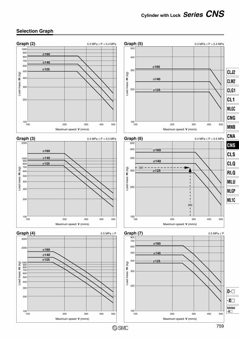
Select a graph based upon the load condition and operating pressure, and then find the point of intersection for the maximum speed found in Step (1) and the load mass. Select the bore size on the line above the point of intersection.
Example)
CylinderstrokeMovement distance
of load
Step (1): From graph (1) find the maximum movement speed of the load∴ Maximum speed V: ≅ 280 mm/s
Step (2): Select Graph(6) based upon the load condition and operating pressure, and then from the intersection of the maximum speed V = 280 mm/s found in Step (1), and the load mass m = 320 kg∴ ø140 → select a CNS140 or larger bore size.
• Load mass: m = 320 kg• Movement distance: st = 400 mm• Movement time: t = 2 s• Load condition: Vertical downward = Load in direction of
rod extension• Operating pressure: P = 0.4 MPa
Load
mov
emen
t tim
e: t
(S
)
Maximum speed: V (mm/s)
Load Condition Operating Pressure
0.4 MPa ≤ Graph (3)
0.3 MPa ≤ Graph (2)
0.5 MPa ≤ Graph (4)
Load in the direction at the rightangle to rod(∗ Being held by a guide)
Load in the direction of rod extensionLoad in the direction of rod retraction
0.4 MPa ≤ Graph (6)
0.3 MPa ≤ Graph (5)
0.5 MPa ≤ Graph (7)
mF
m
F
mF
P0757-P0838-E.qxd 08.11.17 3:04 PM Page 758
100 500400300200
100 500400300200
100
1000
200
300
400
500
2000
700800900
600
100 500400300200100
1000
200
300
400
500125
700
800
900
600
100 500400300200
100 500400300200
100
100
200
300
400
500
600
100 500400300200100
200
300
400
500
1000
2000
3000
400
200
100
300
500
700800900
600
400
200
300
500
700800
600
ø160
ø125
ø125
ø160
ø140
ø125
ø160
ø140
ø125
ø160
ø140
ø125
ø160
ø140
ø125
ø160
ø140
280
320
ø140
759
Cylinder with Lock Series CNS
Selection Graph
Graph (5)Graph (2)
Graph (6)Graph (3)
Graph (7)Graph (4)
Maximum speed: V (mm/s)
Load
mas
s: m
(kg)
Maximum speed: V (mm/s)
Load
mas
s: m
(kg)
Maximum speed: V (mm/s)
Load
mas
s: m
(kg)
Maximum speed: V (mm/s)Lo
ad m
ass:
m (k
g)
Maximum speed: V (mm/s)
Load
mas
s: m
(kg)
Maximum speed: V (mm/s)
Load
mas
s: m
(kg)
0.3 MPa ≤ P < 0.4 MPa 0.3 MPa ≤ P < 0.4 MPa
0.4 MPa ≤ P < 0.5 MPa 0.4 MPa ≤ P < 0.5 MPa
0.5 MPa ≤ P 0.5 MPa ≤ P
CLJ2
CLM2
CLG1
CL1
MLGC
CNG
MNB
CNA
CNS
CLS
CLQ
RLQ
MLU
MLGP
ML1C
Individual-X�
D-�
-X�
P0757-P0838-E.qxd 08.11.17 3:04 PM Page 759
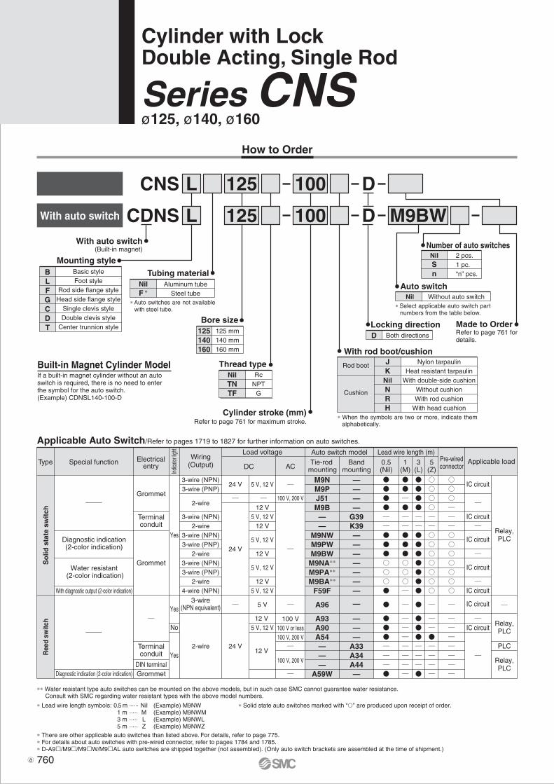
With rod boot/cushionJKNilNRH
Nylon tarpaulinHeat resistant tarpaulin
With double-side cushionWithout cushionWith rod cushion
With head cushion∗ When the symbols are two or more, indicate them
alphabetically.
M9BW
125
125With auto switch
(Built-in magnet)
CNS L
LCDNS
Cylinder stroke (mm)Refer to page 761 for maximum stroke.
D
D
Applicable Auto Switch/Refer to pages 1719 to 1827 for further information on auto switches.
A96
A93A90A54———
A59W
M9NM9PJ51M9B——
M9NWM9PWM9BW
M9NA∗∗
M9PA∗∗
M9BA∗∗
F59F
—
———
A33A34A44—
————
G39K39———————
3-wire(NPN equivalent)
24 V
24 V
24 V
2-wire
3-wire (NPN)3-wire (PNP)
2-wire
3-wire (NPN)2-wire
3-wire (NPN)3-wire (PNP)
2-wire3-wire (NPN)3-wire (PNP)
2-wire4-wire (NPN)
Yes
Yes
Yes
No
Grommet
Terminalconduit
Grommet
Diagnostic indication(2-color indication)
Water resistant (2-color indication)
With diagnostic output (2-color indication)
Diagnostic indication (2-color indication)
Terminalconduit
100 V100 V or less100 V, 200 V
100 V, 200 V
100 V, 200 V
IC circuit
IC circuit
IC circuit
IC circuit
IC circuit
IC circuit
IC circuit
PLC
Relay,PLC
Relay,PLC
Relay,PLC
DIN terminalGrommet
5 V
12 V 5 V, 12 V
12 V
5 V, 12 V
12 V5 V, 12 V
12 V
5 V, 12 V
12 V
5 V, 12 V
12 V5 V, 12 V
With auto switch
Auto switch
Number of auto switches
Locking directionBore size125140160
125 mm140 mm160 mm
Tubing materialNilF ∗
Aluminum tubeSteel tube
Basic styleFoot style
Rod side flange styleHead side flange style
Single clevis styleDouble clevis style
Center trunnion style
BLFGCDT
Mounting style
100
100
Made to OrderRefer to page 761 for details.
Cylinder with LockDouble Acting, Single Rod
Series CNSø125, ø140, ø160
How to Order
∗ Auto switches are not available with steel tube.
Thread typeNilTNTF
RcNPT
G
NilSn
2 pcs. 1 pc. “n” pcs.
∗ Select applicable auto switch part numbers from the table below.
Nil Without auto switch
D Both directions
0.5(Nil)
3(L)
5(Z)
1(M)
∗ Lead wire length symbols: 0.5 m ······ Nil (Example) M9NW1 m ····· M (Example) M9NWM3 m ····· L (Example) M9NWL5 m ····· Z (Example) M9NWZ
∗ Solid state auto switches marked with “” are produced upon receipt of order.
∗ There are other applicable auto switches than listed above. For details, refer to page 775.∗ For details about auto switches with pre-wired connector, refer to pages 1784 and 1785.∗ D-A9/M9/M9W/M9AL auto switches are shipped together (not assembled). (Only auto switch brackets are assembled at the time of shipment.)
∗∗ Water resistant type auto switches can be mounted on the above models, but in such case SMC cannot guarantee water resistance. Consult with SMC regarding water resistant types with the above model numbers.
760
Built-in Magnet Cylinder ModelIf a built-in magnet cylinder without an auto switch is required, there is no need to enter the symbol for the auto switch.(Example) CDNSL140-100-D
Rod boot
Cushion
Ree
d sw
itch
So
lid s
tate
sw
itch
Special functionType Electricalentry
Wiring(Output)
Load voltage
ACDC
Auto switch model Lead wire length (m)Applicable loadPre-wired
connectorTie-rod
mountingBand
mountingIndica
tor lig
ht
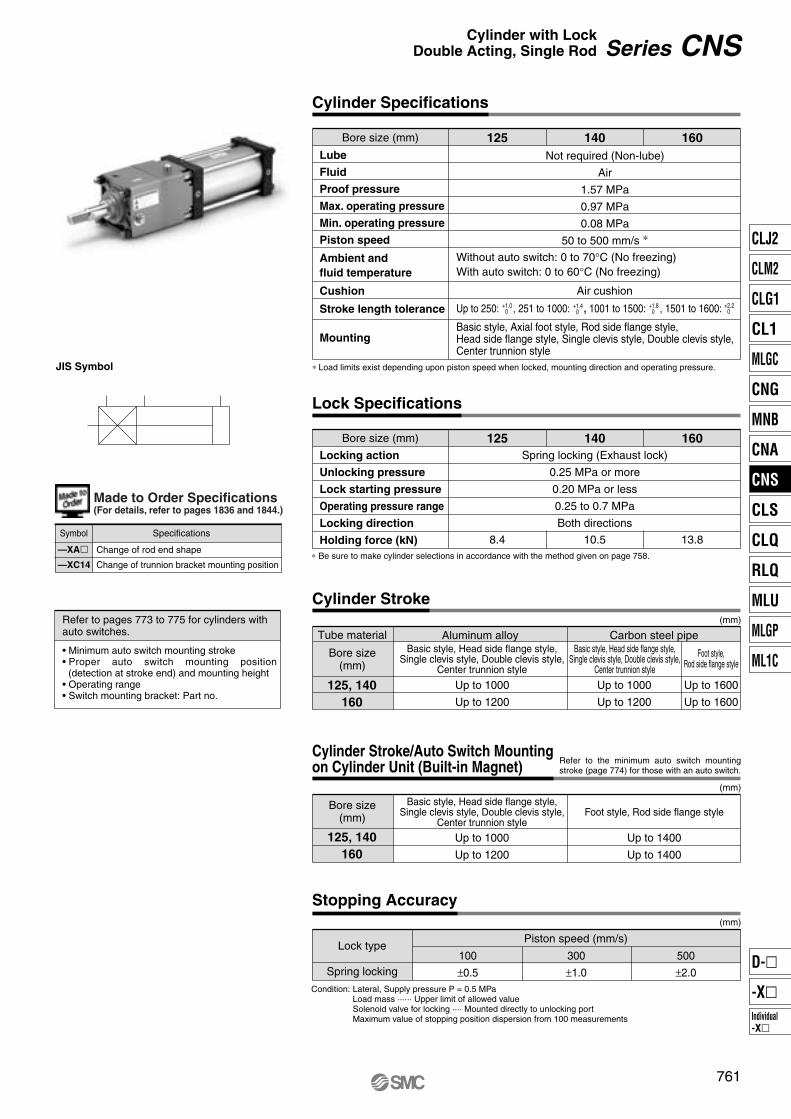
Bore size (mm) 125 140 160
Bore size (mm) 125 140 160
Lube
Fluid
Proof pressure
Max. operating pressure
Min. operating pressure
Piston speed
Cushion
Stroke length tolerance
Mounting
Cylinder Specifications
Not required (Non-lube)
Air
1.57 MPa
0.97 MPa
0.08 MPa
50 to 500 mm/s ∗
Air cushion
Without auto switch: 0 to 70°C (No freezing)With auto switch: 0 to 60°C (No freezing)
Ambient and fluid temperature
∗ Load limits exist depending upon piston speed when locked, mounting direction and operating pressure.
Locking action
Unlocking pressure
Lock starting pressure
Operating pressure range
Locking direction
Holding force (kN)
Spring locking (Exhaust lock)
0.25 MPa or more
0.20 MPa or less
0.25 to 0.7 MPa
Both directions
Bore size(mm)
Tube material
125, 140160
Cylinder Stroke
Aluminum alloy Carbon steel pipe
Up to 1000
Up to 1200
Up to 1000
Up to 1200
Up to 1600
Up to 1600
Lock type
Spring locking
Piston speed (mm/s)
100
±0.5
300
±1.0
500
±2.0
8.4 10.5 13.8
Condition: Lateral, Supply pressure P = 0.5 MPaLoad mass ······ Upper limit of allowed valueSolenoid valve for locking ···· Mounted directly to unlocking port Maximum value of stopping position dispersion from 100 measurements
Basic style, Head side flange style,Single clevis style, Double clevis style,
Center trunnion style
Basic style, Head side flange style,Single clevis style, Double clevis style,
Center trunnion style
Basic style, Head side flange style,Single clevis style, Double clevis style,
Center trunnion style
Foot style,Rod side flange style
Bore size(mm)
125, 140160
Cylinder Stroke/Auto Switch Mountingon Cylinder Unit (Built-in Magnet)
Up to 1000
Up to 1200
Up to 1400
Up to 1400
Foot style, Rod side flange style
∗ Be sure to make cylinder selections in accordance with the method given on page 758.
JIS Symbol
—XA�—XC14
Change of rod end shape
Change of trunnion bracket mounting position
Symbol Specifications
Refer to the minimum auto switch mounting stroke (page 774) for those with an auto switch.
Refer to pages 773 to 775 for cylinders with auto switches.
• Minimum auto switch mounting stroke• Proper auto switch mounting position
(detection at stroke end) and mounting height• Operating range• Switch mounting bracket: Part no.
(mm)
(mm)
(mm)
761
Series CNSCylinder with LockDouble Acting, Single Rod
Made to Order Specifications(For details, refer to pages 1836 and 1844.)
Up to 250: , 251 to 1000: , 1001 to 1500: , 1501 to 1600:+1.00
+1.40
+1.80
+2.20
Basic style, Axial foot style, Rod side flange style, Head side flange style, Single clevis style, Double clevis style, Center trunnion style
Lock Specifications
Stopping Accuracy
CLJ2
CLM2
CLG1
CL1
MLGC
CNG
MNB
CNA
CNS
CLS
CLQ
RLQ
MLU
MLGP
ML1C
Individual-X�
D-�
-X�
P0757-P0838-E.qxd 08.11.17 3:04 PM Page 761
Bore size (mm)
Foot (1)
Rod side flange style (2)
Head side flange style
Single knuckle joint
Double knuckle joint (3)
125
CS1-L12
CS1-FL12
CS1-F12
CS1-C12
CS1-D12
140
CS1-L14
CS1-FL14
CS1-F14
CS1-C14
CS1-D14
160
CS1-L16
CS1-FL16
CS1-F16
CS1-C16
CS1-D16
Note 1) When ordering foot bracket, order 2 pieces per cylinder.Note 2) ø125 to ø160 rod side flange styles use Series CS1 long stroke flanges.Note 3) Clevis pin and cotter pin (2 pcs.) are shipped together with double clevis style.
∗ Refer to page 771 for the accessory bracket dimensions.∗∗ Refer to page 772 when the rod end nut, and the single and double knuckle joints are used together.
∗ Maximum ambient temperature for the rod boot itself.
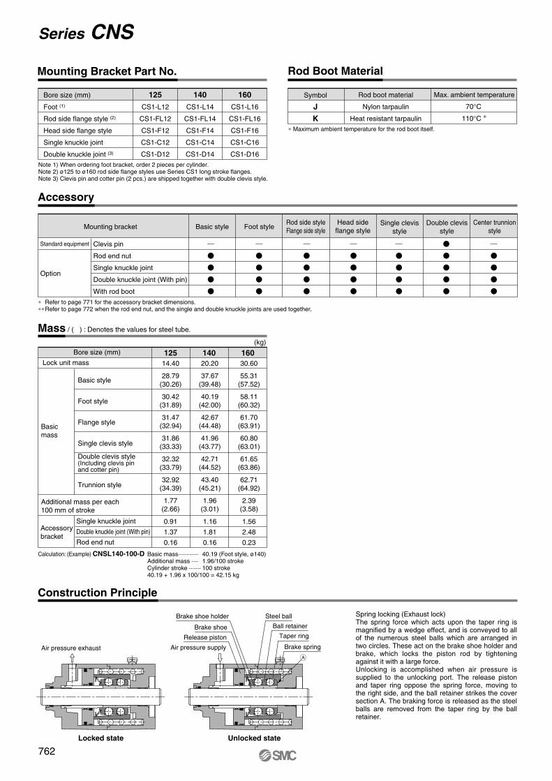
(kg)
125
Basic mass············ 40.19 (Foot style, ø140)Additional mass ···· 1.96/100 strokeCylinder stroke ······· 100 stroke40.19 + 1.96 x 100/100 = 42.15 kg
140 16014.40
28.79(30.26)
30.42(31.89)
31.47(32.94)
31.86(33.33)
32.32(33.79)
32.92(34.39)
1.77(2.66)
0.91
1.37
0.16
20.20
37.67(39.48)
40.19(42.00)
42.67(44.48)
41.96(43.77)
42.71(44.52)
43.40(45.21)
1.96(3.01)
1.16
1.81
0.16
30.60
55.31(57.52)
58.11(60.32)
61.70(63.91)
60.80(63.01)
61.65(63.86)
62.71(64.92)
2.39(3.58)
1.56
2.48
0.23
Calculation: (Example) CNSL140-100-D
762
Series CNS
Mounting Bracket Part No. Rod Boot Material
Symbol
J
K
Rod boot material
Nylon tarpaulin
Heat resistant tarpaulin
Max. ambient temperature
70°C
110°C ∗
Mounting bracket
Standard equipment
Option
Clevis pin
Rod end nut
Single knuckle joint
Double knuckle joint (With pin)
With rod boot
Basic style Foot styleRod side styleFlange side style
Head side flange style
Double clevis style
Center trunnion style
Single clevis style
Accessory
Mass / ( ) : Denotes the values for steel tube.
Bore size (mm)
Basic style
Foot style
Flange style
Single clevis style
Single knuckle joint
Double knuckle joint (With pin)
Rod end nut
Lock unit mass
Trunnion style
Double clevis style(Including clevis pin and cotter pin)
Additional mass per each 100 mm of stroke
Basic mass
Accessory bracket
Construction Principle
Spring locking (Exhaust lock)The spring force which acts upon the taper ring is magnified by a wedge effect, and is conveyed to all of the numerous steel balls which are arranged in two circles. These act on the brake shoe holder and brake, which locks the piston rod by tightening against it with a large force.Unlocking is accomplished when air pressure is supplied to the unlocking port. The release piston and taper ring oppose the spring force, moving to the right side, and the ball retainer strikes the cover section A. The braking force is released as the steel balls are removed from the taper ring by the ball retainer.
Locked state Unlocked state
Brake shoe holder
Brake shoe
Release piston
Air pressure exhaust Air pressure supply
Steel ball
Ball retainer
Taper ring
Brake spring
P0757-P0838-E.qxd 08.11.17 3:05 PM Page 762
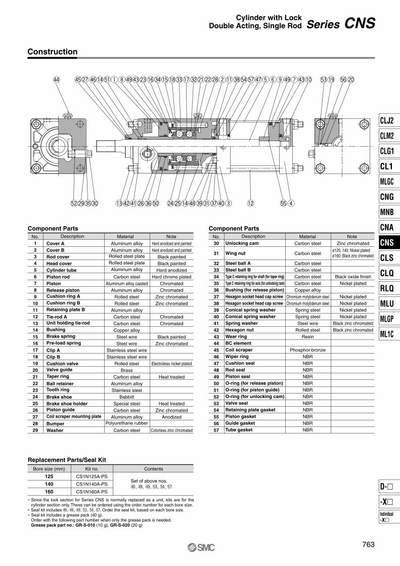
No.1234567891011121314151617181920212223242526272829
Description Material Note
Component Parts
Replacement Parts/Seal Kit
Cover ACover BRod coverHead coverCylinder tubePiston rodPiston Release pistonCushion ring ACushion ring BRetaining plate B
Tie-rod AUnit holding tie-rodBushingBrake springPre-load spring
Clip AClip BCushion valveValve guideTaper ring
Ball retainerTooth ring
Brake shoeBrake shoe holderPiston guideCoil scraper mounting plate
BumperWasher
Unlocking cam
Wing nut
Steel ball ASteel ball BType C retaining ring for shaft (for taper ring)Type C retaining ring for axis (for unlocking cam)Bushing (for release piston)Hexagon socket head cap screwHexagon socket head cap screwConical spring washerConical spring washerSpring washerHexagon nutWear ringBC elementCoil scraperWiper ringCushion sealRod sealPiston sealO-ring (for release piston)O-ring (for piston guide)O-ring (for unlocking cam)Valve sealRetaining plate gasketPiston gasketGuide gasketTube gasket
Aluminum alloyAluminum alloy
Rolled steel plateRolled steel plateAluminum alloy
Carbon steelAluminum alloy casted
Aluminum alloyRolled steelRolled steel
Aluminum alloyCarbon steelCarbon steelCopper alloy
Steel wireSteel wire
Stainless steel wireStainless steel wire
Rolled steelBrass
Carbon steelAluminum alloyStainless steel
BabbittSpecial steelCarbon steel
Aluminum alloyPolyurethane rubber
Carbon steel
Carbon steel
Carbon steel
Carbon steelCarbon steelCarbon steelCarbon steelCopper alloy
Chromium molybdenum steelChromium molybdenum steel
Spring steelSpring steelSteel wire
Rolled steelResin
Phosphor bronzeNBRNBRNBRNBRNBRNBRNBRNBRNBRNBRNBRNBR
Hard anodized and paintedHard anodized and painted
Black paintedBlack paintedHard anodized
Hard chrome platedChromatedChromated
Zinc chromatedZinc chromated
ChromatedChromated
Black paintedZinc chromated
Electroless nickel plated
Heat treated
Heat treatedZinc chromated
Anodized
Colorless zinc chromated
Bore size (mm)
125
140
160
Kit no.
CS1N125A-PS
CS1N140A-PS
CS1N160A-PS
Contents
No.30
31
3233343536373839404142434445464748495051525354555657
Description Material Note
Component Parts
Set of above nos.$6, $8, $9, %3, %4, %7
Zinc chromated
Black oxide finishNickel plated
Nickel platedNickel platedNickel platedNickel plated
Black zinc chromatedBlack zinc chromated
ø125, 140: Nickel platedø160: Black zinc chromated
763
Series CNSCylinder with LockDouble Acting, Single Rod
Construction
∗ Since the lock section for Series CNS is normally replaced as a unit, kits are for the cylinder section only. These can be ordered using the order number for each bore size.
∗ Seal kit includes $6, $8, $9, %3, %4, %7. Order the seal kit, based on each bore size.∗ Seal kit includes a grease pack (40 g).
Order with the following part number when only the grease pack is needed.Grease pack part no.: GR-S-010 (10 g), GR-S-020 (20 g)
CLJ2
CLM2
CLG1
CL1
MLGC
CNG
MNB
CNA
CNS
CLS
CLQ
RLQ
MLU
MLGP
ML1C
Individual-X�
D-�
-X�
P0757-P0838-E.qxd 08.11.17 3:05 PM Page 763
125140160
Up to 1000
Up to 1000
Up to 1200
125140160
30 to 1000
30 to 1000
30 to 1200
125140160
CL
T
MM
M GA
GGFA GB
ALA K F
VABN
S + Stroke
ZZ + Stroke
N N
MH
GLGR
CB
Q
øE
øD
øE
A
VBP (Rc, NPT, G)Unlocking port 2 x P (Rc, NPT, G)
Cylinder port
Rc BQ plug with breathing holeBC element
CB
2 x MAThread effective depth R
4 x J
Width across flats KAø
75
40l
h + l
ZZ1 + l + Stroke
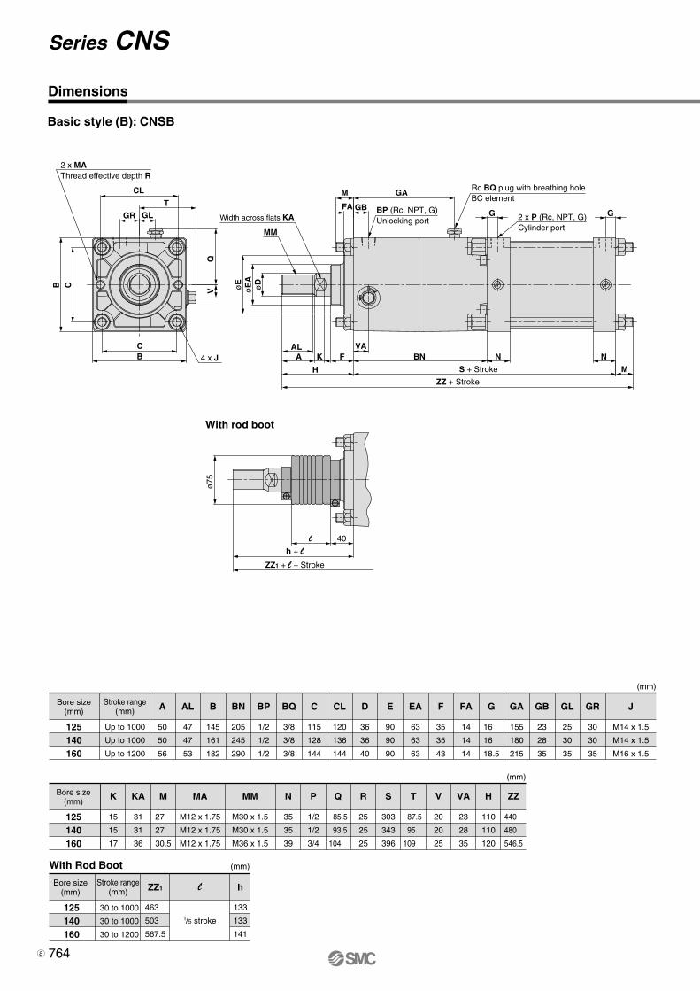
A
50
50
56
AL
47
47
53
B
145
161
182
BN
205
245
290
BP
1/2
1/2
1/2
BQ
3/8
3/8
3/8
C
115
128
144
CL
120
136
144
D
36
36
40
E
90
90
90
EA
63
63
63
F
35
35
43
FA
14
14
14
G
16
16
18.5
GA
155
180
215
GB
23
28
35
GL
25
30
35
GR
30
30
35
J
M14 x 1.5
M14 x 1.5
M16 x 1.5
K
15
15
17
KA
31
31
36
M
27
27
30.5
MA
M12 x 1.75
M12 x 1.75
M12 x 1.75
MM
M30 x 1.5
M30 x 1.5
M36 x 1.5
N
35
35
39
P
1/2
1/2
3/4
Q
85.5
93.5
104
R
25
25
25
S
303
343
396
T
87.5
95
109
V
20
20
25
VA
23
28
35
H
110
110
120
ZZ1
463
503
567.5
h
133
133
141
ZZ
440
480
546.5
With rod boot
l
1/5 stroke
764
Series CNS
Bore size(mm)
Stroke range(mm)
With Rod Boot
Bore size(mm)
Bore size(mm)
Stroke range(mm)
Basic style (B): CNSB
Dimensions
(mm)
(mm)
(mm)
3-02-37-CNS.qxd 09.11.11 1:41 PM Page 1
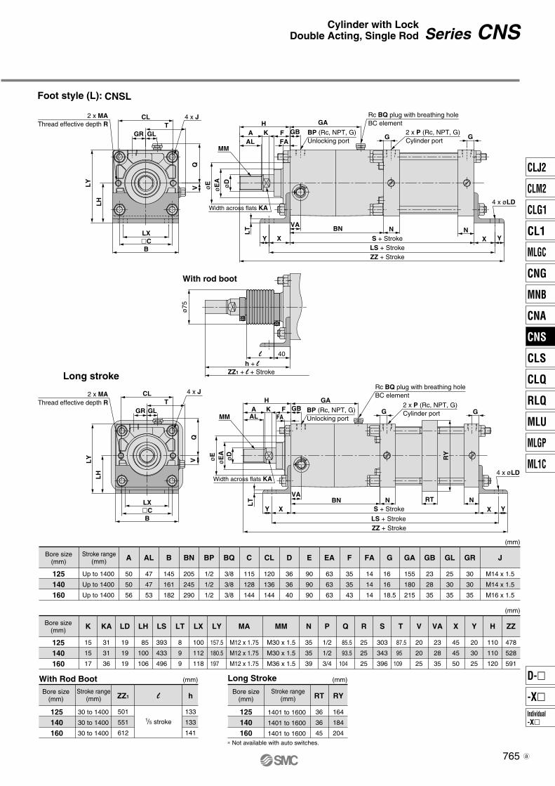
Foot style (L): CNSL
125140160
Up to 1400
Up to 1400
Up to 1400
125140160
30 to 1400
30 to 1400
30 to 1400
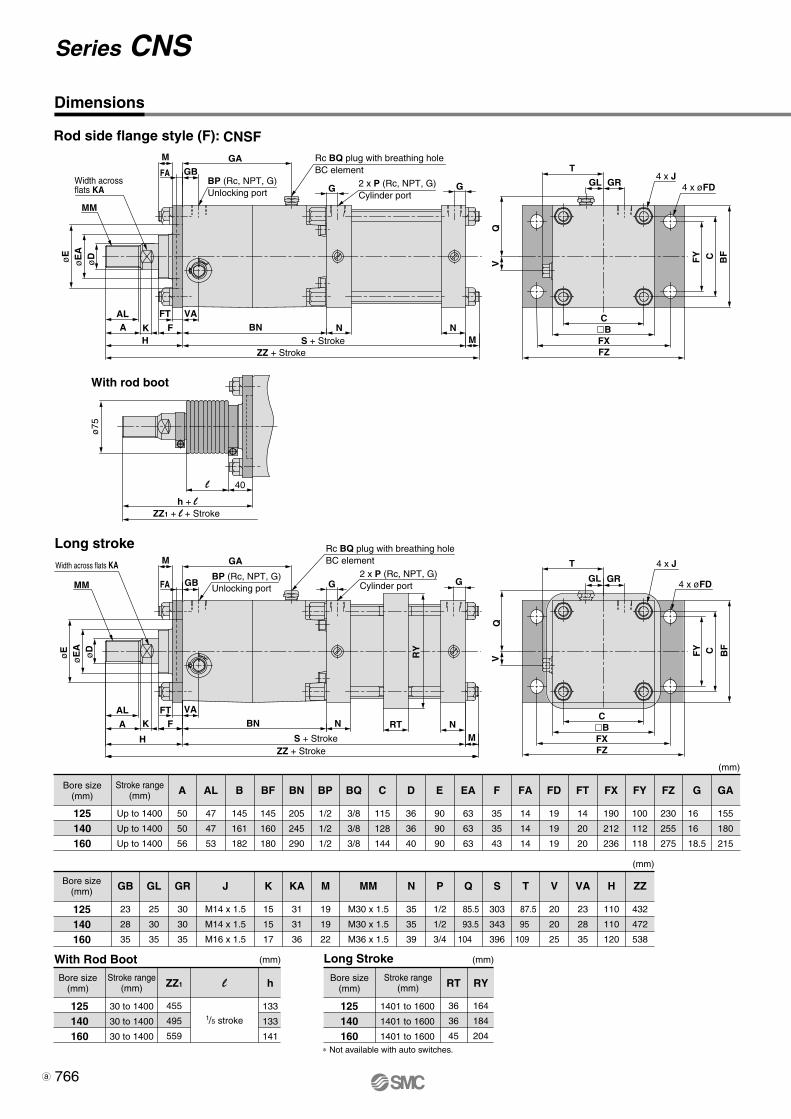
125140160
A
50
50
56
AL
47
47
53
B
145
161
182
BN
205
245
290
BP
1/2
1/2
1/2
BQ
3/8
3/8
3/8
C
115
128
144
CL
120
136
144
D
36
36
40
E
90
90
90
EA
63
63
63
F
35
35
43
FA
14
14
14
G
16
16
18.5
GA
155
180
215
GB
23
28
35
GL
25
30
35
GR
30
30
35
J
M14 x 1.5
M14 x 1.5
M16 x 1.5
K
15
15
17
KA
31
31
36
ZZ1
501
551
612
l
125140160
1401 to 1600
1401 to 1600
1401 to 1600
Long Stroke
RT
36
36
45
RY
164
184
204
Long stroke
CL
CL
GR GLT
TGLGR
LX�CB
Q
LY
LH
V
2 x MAThread effective depth R
4 x J
MM
GA
GGFA
GB
ALA K F
VABN
S + Stroke
ZZ + StrokeLS + Stroke
N NXX YY
LT
H
øE øD
øE
A
BP (Rc, NPT, G)Unlocking port
2 x P (Rc, NPT, G)Cylinder port
Rc BQ plug with breathing holeBC element
Width across flats KA4 x øLD
ø75
40l
h + lZZ1 + l + Stroke
2 x MAThread effective depth R
øE øD
øE
A
LX�CB
Q
LY
LH
V
4 x J
AL FAA K
H
MM
GAF GB BP (Rc, NPT, G)
Unlocking port
Width across flats KA
LT
VABN
S + Stroke
LS + StrokeZZ + Stroke
N RT NXX YY
4 x øLD
GG2 x P (Rc, NPT, G)Cylinder port
Rc BQ plug with breathing holeBC element
RY
LD
19
19
19
LH
85
100
106
LS
393
433
496
LT
8
9
9
LX
100
112
118
LY
157.5
180.5
197
MM
M30 x 1.5
M30 x 1.5
M36 x 1.5
MA
M12 x 1.75
M12 x 1.75
M12 x 1.75
N
35
35
39
P
1/2
1/2
3/4
Q
85.5
93.5
104
R
25
25
25
S
303
343
396
T
87.5
95
109
V
20
20
25
VA
23
28
35
X
45
45
50
Y
20
30
25
H
110
110
120
ZZ
478
528
591
∗ Not available with auto switches.
With rod boot
1/5 stroke
h
133
133
141
765
Series CNSCylinder with LockDouble Acting, Single Rod
Bore size(mm)
Stroke range(mm)
Bore size(mm)
Stroke range(mm)
With Rod Boot
Bore size(mm)
Bore size(mm)
Stroke range(mm)
(mm)
(mm)
(mm)(mm)
CLJ2
CLM2
CLG1
CL1
MLGC
CNG
MNB
CNA
CNS
CLS
CLQ
RLQ
MLU
MLGP
ML1C
Individual-X�
D-�
-X�
3-02-37-CNS.qxd 09.11.11 1:41 PM Page 2
125140160
Up to 1400
Up to 1400
Up to 1400
125140160
30 to 1400
30 to 1400
30 to 1400
125140160
A
50
50
56
GB
23
28
35
ZZ1
455
495
559
l
1/5 stroke
125140160
1401 to 1600
1401 to 1600
1401 to 1600
Long Stroke
RT
36
36
45
RY
164
184
204
øE
øD
øE
A
MM
Width acrossflats KA
FA
M
GBGA
G G
ALA K F BN N N
M
FT VA
H S + StrokeZZ + Stroke
BP (Rc, NPT, G)Unlocking port
2 x P (Rc, NPT, G)Cylinder port
Rc BQ plug with breathing holeBC element T
GL GR
C�BFXFZ
C
Q
FY
BF
C
V
4 x J4 x øFD
ø75
40l
h + lZZ1 + l + Stroke
øE øD
øE
A
MM
Width across flats KA
FA
M
GB
GA
G GBP (Rc, NPT, G)Unlocking port
2 x P (Rc, NPT, G)Cylinder port
Rc BQ plug with breathing holeBC element
AL
A K F BN N NRTM
FT VA
H S + StrokeZZ + Stroke
RY
T
GL GR
C�BFXFZ
Q
FY
BF
V
4 x J
4 x øFD
AL
47
47
53
GL
25
30
35
B
145
161
182
GR
30
30
35
BF
145
160
180
J
M14 x 1.5
M14 x 1.5
M16 x 1.5
BN
205
245
290
BP
1/2
1/2
1/2
K
15
15
17
BQ
3/8
3/8
3/8
KA
31
31
36
C
115
128
144
M
19
19
22
D
36
36
40
MM
M30 x 1.5
M30 x 1.5
M36 x 1.5
E
90
90
90
EA
63
63
63
N
35
35
39
F
35
35
43
P
1/2
1/2
3/4
FA
14
14
14
Q
85.5
93.5
104
FD
19
19
19
S
303
343
396
FT
14
20
20
T
87.5
95
109
FX
190
212
236
V
20
20
25
FY
100
112
118
VA
23
28
35
FZ
230
255
275
H
110
110
120
G
16
16
18.5
ZZ
432
472
538
GA
155
180
215
∗ Not available with auto switches.
Long stroke
With rod boot
h
133
133
141
766
Series CNS
Rod side flange style (F): CNSF
Dimensions
Bore size(mm)
Stroke range(mm)
Bore size(mm)
Stroke range(mm)
With Rod Boot
Bore size(mm)
Bore size(mm)
Stroke range(mm)
(mm)
(mm)
(mm)(mm)
3-02-37-CNS.qxd 09.11.11 1:41 PM Page 3
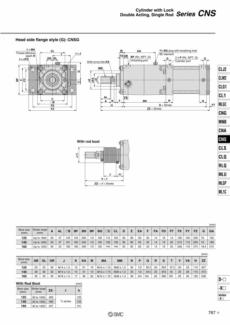
Head side flange style (G): CNSG
With rod boot
2 x MAThread effective
depth RT
CL
GLGR
C�BFXFZ
C
Q
FY
BF
V
4 x J
4 x øFD
MM
GA
GB
M
G GFA
ALA K F
VABN
S + StrokeZZ + Stroke
N NFTH
øE øD
øE
A
BP (Rc, NPT, G)Unlocking port
2 x P (Rc, NPT, G)Cylinder port
Rc BQ plug with breathing holeBC element
Width across flats KA
ø75
40l
h + l
ZZ1 + l + Stroke
125140160
Up to 1000
Up to 1000
Up to 1200
125140160
30 to 1000
30 to 1000
30 to 1200
A
50
50
56
ZZ1
450
496
557
l
1/5 stroke
GB
23
28
35
125140160
AL
47
47
53
GL
25
30
35
�B
145
161
182
GR
30
30
35
BF
145
160
180
J
M14 x 1.5
M14 x 1.5
M16 x 1.5
MM
M30 x 1.5
M30 x 1.5
M36 x 1.5
MA
M12 x 1.75
M12 x 1.75
M12 x 1.75
BN
205
245
290
BP
1/2
1/2
1/2
K
15
15
17
BQ
3/8
3/8
3/8
KA
31
31
36
�C
115
128
144
M
19
19
22
CL
120
136
144
D
36
36
40
E
90
90
90
EA
63
63
63
F
35
35
43
N
35
35
39
FA
14
14
14
P
1/2
1/2
3/4
FD
19
19
19
Q
85.5
93.5
104
FT
14
20
20
R
25
25
25
FX
190
212
236
S
303
343
396
FY
100
112
118
T
87.5
95
109
FZ
230
255
275
V
20
20
25
G
16
16
18.5
VA
23
28
35
GA
155
180
215
H
110
110
120
ZZ
427
473
536
h
133
133
141
767
Series CNSCylinder with LockDouble Acting, Single Rod
Bore size(mm)
Stroke range(mm)
With Rod Boot
Bore size(mm)
Bore size(mm)
Stroke range(mm)
(mm)
(mm)
(mm)
CLJ2
CLM2
CLG1
CL1
MLGC
CNG
MNB
CNA
CNS
CLS
CLQ
RLQ
MLU
MLGP
ML1C
Individual-X�
D-�
-X�
3-02-37-CNS.qxd 09.11.11 1:41 PM Page 4

Single clevis style (C): CNSC
125140160
Up to 1000
Up to 1000
Up to 1200
125140160
30 to 1000
30 to 1000
30 to 1200
A
50
50
56
ZZ1
530
583
653
Z1
501
551
617
l
1/5 stroke
125140160
MM
GA
GB
M
G GFA
ALA K F
VABN
S + Stroke
ZZ + StrokeZ + Stroke
N N UL
RR
CXCT
H
øE øD
øE
A
BP (Rc, NPT, G)Unlocking port
2 x P (Rc, NPT, G)Cylinder port
øCD hole H10Shaft d9
Rc BQ plug with breathing holeBC element
Width across flats KA
T
QV
GR GL
2 x MAThread effective depth R
CB
CB
4 x J
With rod boot
ø75
40l
h + l
ZZ1 + l + StrokeZ1 + l + Stroke
GR
30
30
35
AL
47
47
53
J
M14 x 1.5
M14 x 1.5
M16 x 1.5
B
145
161
182
BN
205
245
290
K
15
15
17
BP
1/2
1/2
1/2
KA
31
31
36
BQ
3/8
3/8
3/8
L
65
75
80
C
115
128
144
M
19
19
22
CDH10
25
28
32
MA
M12 x 1.75
M12 x 1.75
M12 x 1.75
MM
M30 x 1.5
M30 x 1.5
M36 x 1.5
CL
120
136
144
CT
17
17
20
CX
32
36
40
N
35
35
39
P
1/2
1/2
3/4
D
36
36
40
Q
85.5
93.5
104
E
90
90
90
R
25
25
25
EA
63
63
63
RR
29
32
36
F
35
35
43
S
303
343
396
FA
14
14
14
T
87.5
95
109
G
16
16
18.5
U
35
40
45
GA
155
180
215
V
20
20
25
GB
23
28
35
VA
23
28
35
GL
25
30
35
H
110
110
120
Z
478
528
596
ZZ
507
560
632
+0.084 0
+0.084 0
+0.100 0
–0.1–0.3
–0.1–0.3
–0.1–0.3
CL
h
133
133
141
768
Series CNS
Dimensions
Bore size(mm)
Stroke range(mm)
With Rod Boot
Bore size(mm)
Bore size(mm)
Stroke range(mm)
(mm)
(mm)
(mm)
3-02-37-CNS.qxd 09.11.11 1:41 PM Page 5
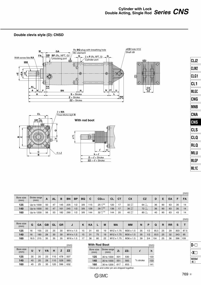
Double clevis style (D): CNSD
MM
GA
GB
M
G GFA
AL
A K F
VA
BN
S + Stroke
ZZ + StrokeZ + Stroke
N N U
LRR
CXCZCT
H
øE øD
øE
A
BP (Rc, NPT, G)Unlocking port
2 x P (Rc, NPT, G)Cylinder port
øCD hole H10Shaft d9
Rc BQ plug with breathing holeBC element
Width across flats KA
CLT
QV
GR GL
2 x MAThread effective depth R
CB
4 x J
With rod boot
ø75
40l
h + l
ZZ1 + l + StrokeZ1 + l + Stroke
125140160
Up to 1000
Up to 1000
Up to 1200
125140160
30 to 1000
30 to 1000
30 to 1200
With Rod Boot
125140160
125140160
A
50
50
56
ZZ1
530
583
653
Z1
501
551
617
l
GL
25
30
35
G
16
16
18.5
GA
155
180
215
GB
23
28
35
AL
47
47
53
GR
30
30
35
B
145
161
182
J
M14 x 1.5
M14 x 1.5
M16 x 1.5
MA
M12 x 1.75
M12 x 1.75
M12 x 1.75
MM
M30 x 1.5
M30 x 1.5
M36 x 1.5
BN
205
245
290
H
110
110
120
BP
1/2
1/2
1/2
K
15
15
17
Z
478
528
596
BQ
3/8
3/8
3/8
KA
31
31
36
ZZ
507
560
632
C
115
128
144
L
65
75
80
CDH10
25
28
32
M
19
19
22
CL
120
136
144
CT
17
17
20
N
35
35
39
P
1/2
1/2
3/4
Q
85.5
93.5
104
D
36
36
40
R
25
25
25
E
90
90
90
RR
29
32
36
EA
63
63
63
S
303
343
396
F
35
35
43
T
87.5
95
109
FA
14
14
14
+0.084 0
+0.084 0
+0.100 0
CX
32
36
40
CZ
64
72
80
+0.3+0.1
0–0.2
0–0.2
0–0.2
+0.3+0.1
+0.3+0.1
U
35
40
45
V
20
20
25
VA
23
28
35
∗ Clevis pin and cotter pin are shipped together.
B C
1/5 stroke
h
133
133
141
769
Series CNSCylinder with LockDouble Acting, Single Rod
Bore size(mm)
Bore size(mm)
Bore size(mm)
Stroke range(mm)
Bore size(mm)
Stroke range(mm)
(mm)
(mm)
(mm)(mm)
CLJ2
CLM2
CLG1
CL1
MLGC
CNG
MNB
CNA
CNS
CLS
CLQ
RLQ
MLU
MLGP
ML1C
Individual-X�
D-�
-X�
3-02-37-CNS.qxd 09.11.11 1:41 PM Page 6
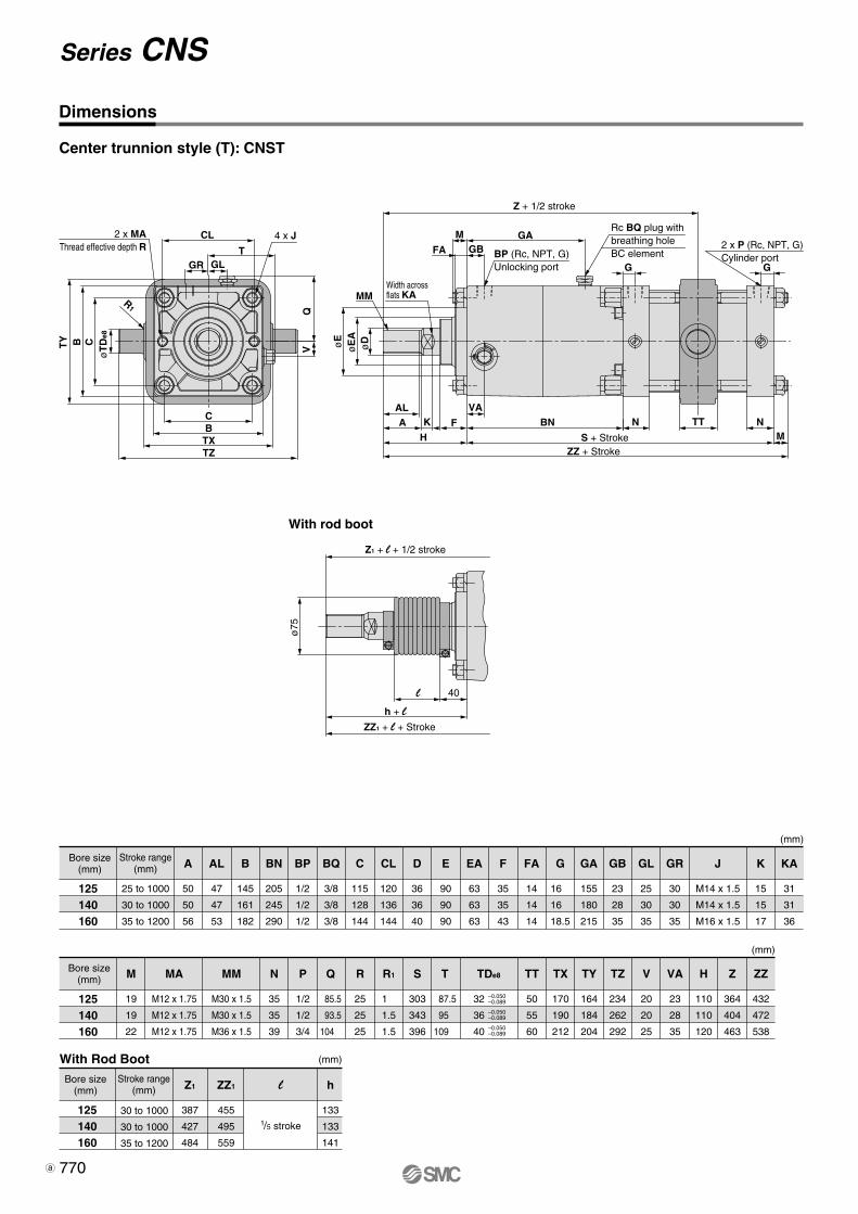
Center trunnion style (T): CNST
CL
TGLGR
R1
CBTXTZ
TY
øT
De8
QV
2 x MAThread effective depth R
4 x J
MM
GAGB
M
G G
FA
ALA K F
VABN
S + StrokeZZ + Stroke
Z + 1/2 stroke
N NTTMH
øE
øD
øE
A
BP (Rc, NPT, G)Unlocking port
2 x P (Rc, NPT, G)Cylinder port
Rc BQ plug withbreathing holeBC element
Width acrossflats KA
ø75
40l
h + l
ZZ1 + l + Stroke
Z1 + l + 1/2 stroke
With rod boot
125140160
25 to 1000
30 to 1000
35 to 1200
125140160
30 to 1000
30 to 1000
35 to 1200
A
50
50
56
ZZ1
455
495
559
Z1
387
427
484
l
125140160
M
19
19
22
AL
47
47
53
MM
M30 x 1.5
M30 x 1.5
M36 x 1.5
MA
M12 x 1.75
M12 x 1.75
M12 x 1.75
B
145
161
182
BN
205
245
290
N
35
35
39
BP
1/2
1/2
1/2
P
1/2
1/2
3/4
BQ
3/8
3/8
3/8
Q
85.5
93.5
104
C
115
128
144
R
25
25
25
CL
120
136
144
R1
1
1.5
1.5
D
36
36
40
S
303
343
396
E
90
90
90
T
87.5
95
109
EA
63
63
63
TDe8
32
36
40
F
35
35
43
FA
14
14
14
TT
50
55
60
G
16
16
18.5
TX
170
190
212
GA
155
180
215
TY
164
184
204
GB
23
28
35
TZ
234
262
292
GL
25
30
35
V
20
20
25
GR
30
30
35
VA
23
28
35
J
M14 x 1.5
M14 x 1.5
M16 x 1.5
H
110
110
120
Z
364
404
463
K
15
15
17
ZZ
432
472
538
KA
31
31
36
–0.050–0.089
–0.050–0.089
–0.050–0.089
B C
1/5 stroke
h
133
133
141
770
Series CNS
Dimensions
Bore size(mm)
Stroke range(mm)
With Rod Boot
Bore size(mm)
Bore size(mm)
Stroke range(mm)
(mm)
(mm)
(mm)
3-02-37-CNS.qxd 09.11.11 1:41 PM Page 7
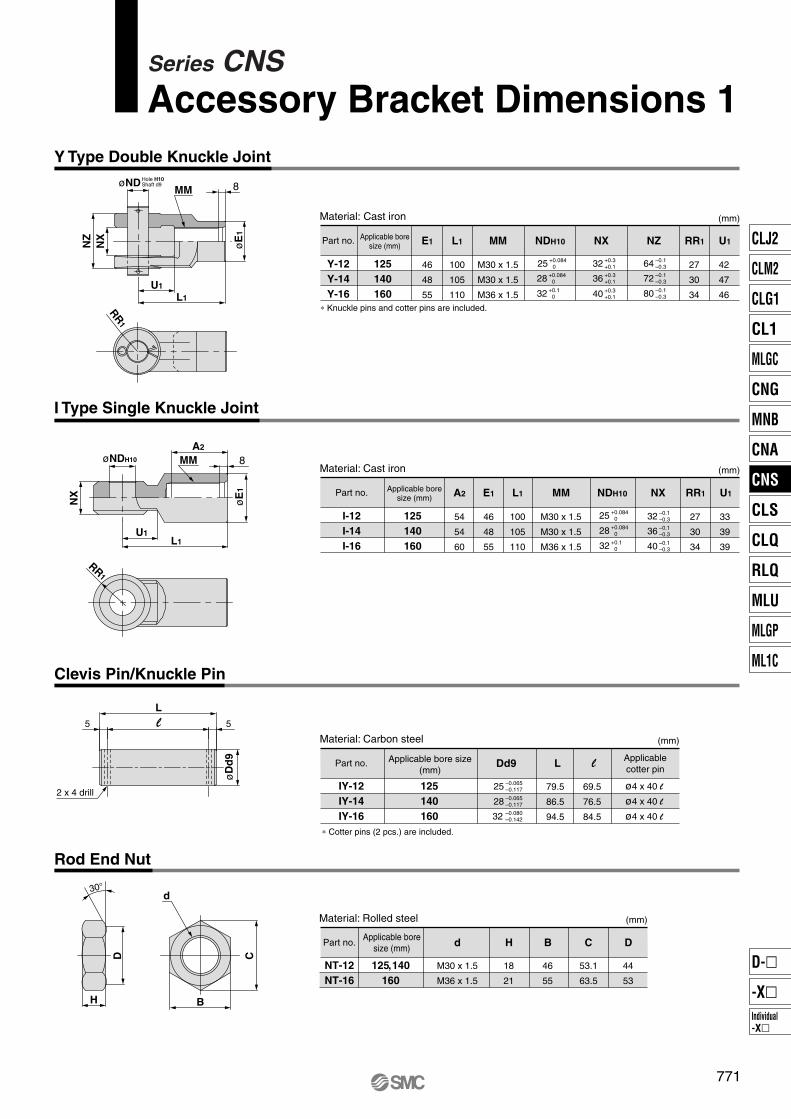
Part no.
Y-12Y-14Y-16
125140160
Applicable boresize (mm) E1 L1 MM NZ RR1 U1
M30 x 1.5
M30 x 1.5
M36 x 1.5
64 –0.1–0.3
72 –0.1–0.3
80 –0.1–0.3
46
48
55
100
105
110
27
30
34
42
47
46
Material: Cast iron
Part no.
IY-12IY-14IY-16
125140160
Dd9 L l
25 –0.065–0.117
28 –0.065–0.117
79.5
86.5
94.5
Material: Carbon steel
Applicable bore size(mm)
Applicablecotter pin
32 –0.080–0.142
69.5
76.5
84.5
ø4 x 40 l
ø4 x 40 l
ø4 x 40 l
Part no.
NT-12NT-16
125, 140160
Applicable boresize (mm) d H
M30 x 1.5
M36 x 1.5
18
21
Material: Rolled steel
B
46
55
C
53.1
63.5
D
44
53
RR1
l
L5 5
øD
d9
2 x 4 drill
NX
32 +0.3+0.1
36 +0.3+0.1
40 +0.3+0.1
25 +0.084
0
28 +0.084
0
32 +0.1
0
NDH10
Part no.
I-12I-14I-16
125140160
Applicable boresize (mm) A2 E1 MM NX RR1 U1
M30 x 1.5
M30 x 1.5
M36 x 1.5
54
54
60
46
48
55
27
30
34
33
39
39
Material: Cast iron
NDH10
25 +0.084
0
28 +0.084
0
32 +0.1
0
L1
100
105
110
32 –0.1–0.3
36 –0.1–0.3
40 –0.1–0.3
MM 8
U1
L1
NX
NZ
øNDHole H10Shaft d9
øE
1
RR1
MMA2
8
L1U1
NX
øNDH10
øE
1
30°
H B
d
D C
∗ Knuckle pins and cotter pins are included.
∗ Cotter pins (2 pcs.) are included.
771
Series CNSAccessory Bracket Dimensions 1
Y Type Double Knuckle Joint
I Type Single Knuckle Joint
Clevis Pin/Knuckle Pin
Rod End Nut
(mm)
(mm)
(mm)
(mm)
CLJ2
CLM2
CLG1
CL1
MLGC
CNG
MNB
CNA
CNS
CLS
CLQ
RLQ
MLU
MLGP
ML1C
Individual-X�
D-�
-X�
P0757-P0838-E.qxd 08.11.17 3:05 PM Page 771
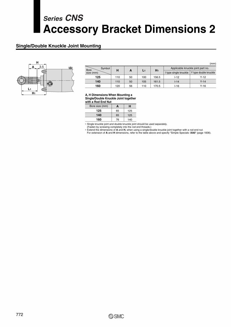
Single/Double Knuckle Joint Mounting
HA
L1
H1
125140160
I type single knuckle
I-12
I-14
I-16
Applicable knuckle joint part no.
Y type double knuckle
Y-12
Y-14
Y-16
H1
156.5
161.5
170.5
L1
100
105
110
H
110
110
120
A
50
50
56
Bore size (mm)
125140160
H125
125
140
A65
65
76
A, H Dimensions When Mounting a Single/Double Knuckle Joint together with a Rod End Nut
3.5
772
Series CNSAccessory Bracket Dimensions 2
SymbolBoresize (mm)
∗ Single knuckle joint and double knuckle joint should be used separately.(Fasten by screwing completely into the rod end threads.)
∗ Extend the dimensions of A and H, when using a single/double knuckle joint together with a rod end nut.For extension of A and H dimensions, refer to the table above and specify “Simple Specials -XA0” (page 1836).
(mm)
P0757-P0838-E.qxd 08.11.17 3:05 PM Page 772
D-A5�/A6�D-A44
D-A3�D-G39/K39
D-F5�/J5�/D-F5NTLD-F5BAL/F59FD-F5�W/J59W
49
36
56 34
A B
≅ Hs
≅ H
t≅
Ht
30
Auto switch
A B
34.5
36
56
≅ HsAuto switch
A B
≅ H
t≅
Ht
≅ Hs33
Auto switch
A B
D-Z7�/Z80D-Y59�/Y69�/Y7P/Y7PVD-Y7�W/Y7�WVD-Y7BAL
D-A9�/A9�VD-M9�/M9�VD-M9�W/M9�WVD-M9�AL/M9�AVL
20
≅ Hs
≅ H
t≅
Ht
A
B
Auto Switch Mounting Height
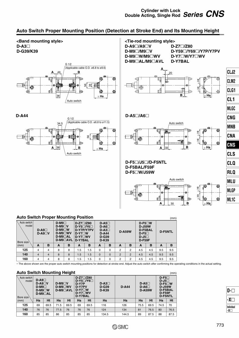
D-A9�D-A9�VD-M9�D-M9�WD-M9�AL
Hs69
76
85
Ht69.5
76
85
D-M9�VD-M9�WVD-M9�AVL
Hs71.5
77.5
86
Ht69.5
76
85
D-Z7�/Z80D-Y5�/Y6�D-Y7PD-Y7PVD-Y7�WD-Y7�WVD-Y7BALHs69
76
85
Ht69.5
76
85
D-A3�D-G39D-K39
Hs116
124
134.5
D-A44
Hs126
134
144.5
D-A5�D-A6�D-A59W
Hs75.5
81
89
Ht69.5
76.5
87.5
D-F5�D-J5�D-F5�WD-J59WD-F5BALD-F59FD-F5NTLHs74.5
80
88
Ht70
76.5
87.5
125140160
Auto Switch Proper Mounting Position
D-A9�D-A9�V
A4
4
4
B4
4
4
D-M9�D-M9�VD-M9�WD-M9�WVD-M9�ALD-M9�AVL
A8
8
8
B8
8
8
125140160
∗ The above shown are the proper auto switch mounting positions for detection at stroke end. Adjust the auto switch after confirming the operating conditions in the actual setting.
D-Z7�/Z80D-Y5�/Y6�D-Y7P/Y7PVD-Y7�WD-Y7�WVD-Y7BAL
A1.5
1.5
1.5
B1.5
1.5
1.5
D-A5�D-A6�D-A3�D-A44D-G39D-K39
A0
0
0
B0
0
0
D-A59W
A2
2
2
B2
2
2
D-F5�WD-J59WD-F5BALD-F5�D-J5�D-F59F
A4.5
4.5
4.5
B4.5
4.5
4.5
D-F5NTL
A9.5
9.5
9.5
B9.5
9.5
9.5
773
Series CNSCylinder with LockDouble Acting, Single Rod
Auto Switch Proper Mounting Position (Detection at Stroke End) and Its Mounting Height
<Band mounting style> <Tie-rod mounting style>
G 1/2 (Applicable cable O.D. ø6.8 to ø9.6)
G 1/2 (Applicable cable O.D. ø6.8 to ø11.5)
Auto switch
≅ Hs
Bore size(mm)
Auto switchmodel
Bore size(mm)
Auto switchmodel
(mm)
(mm)
CLJ2
CLM2
CLG1
CL1
MLGC
CNG
MNB
CNA
CNS
CLS
CLQ
RLQ
MLU
MLGP
ML1C
Individual-X�
D-�
-X�
P0757-P0838-E.qxd 08.11.17 3:05 PM Page 773
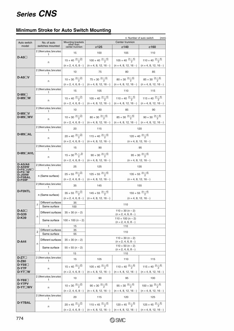
n: Number of auto switch (mm)
D-A9�
D-A9�V
D-M9�D-M9�W
D-M9�VD-M9�WV
D-M9�AL
2 (Different surfaces, Same surface)1
n
2 (Different surfaces, Same surface)1
2 (Different surfaces, Same surface)1
2 (Different surfaces, Same surface)1
2 (Different surfaces, Same surface)1
n
n
n
n
10015
10
15
10
20
(n = 2, 4, 6, 8 ···)
15 + 40(n – 2)
2
(n = 4, 8, 12, 16 ···)
100 + 40(n – 4)
2
75
(n = 4, 8, 12, 16 ···)
75 + 30(n – 4)
2
105
(n = 4, 8, 12, 16 ···)
105 + 40(n – 4)
2
80
(n = 4, 8, 12, 16 ···)
80 + 30(n – 4)
2
115
(n = 4, 8, 12, 16 ···)
115 + 40(n – 4)
2
105
(n = 4, 8, 12, 16 ···)
105 + 40(n – 4)
2
80
(n = 4, 8, 12, 16 ···)
80 + 30(n – 4)
2
110
(n = 4, 8, 12, 16 ···)
110 + 40(n – 4)
2
D-A5/A6D-A59WD-F5�/J5�D-F5�WD-J59WD-F5BALD-F59F
2 (Different surfaces, Same surface)1
n (Same surface)
12525
(n = 2, 4, 6, 8 ···)
25 + 55(n – 2)
2
(n = 4, 8, 12, 16 ···)
125 + 55(n – 4)
2
135
(n = 4, 8, 12, 16 ···)
135 + 55(n – 4)
2
D-F5NTL
2 (Different surfaces, Same surface)1
n (Same surface)
14535
(n = 2, 4, 6, 8 ···)
35 + 55(n – 2)
2
(n = 4, 8, 12, 16 ···)
145 + 55(n – 4)
2
155
(n = 4, 8, 12, 16 ···)
155 + 55(n – 4)
2
D-Z7�D-Z80D-Y59�D-Y7PD-Y7�W
2 (Different surfaces, Same surface)1
n
10515
(n = 2, 4, 6, 8 ···)
15 + 40(n – 2)
2
(n = 4, 8, 12, 16 ···)
105 + 40(n – 4)
2
110
(n = 4, 8, 12, 16 ···)
110 + 40(n – 4)
2
115
(n = 4, 8, 12, 16 ···)
115 + 40(n – 4)
2
2 (Different surfaces, Same surface)1
n
9010
(n = 2, 4, 6, 8 ···)
10 + 30(n – 2)
2
(n = 4, 8, 12, 16 ···)
90 + 30(n – 4)
2
95
(n = 4, 8, 12, 16 ···)
95 + 30(n – 4)
2
100
(n = 4, 8, 12, 16 ···)
100 + 30(n – 4)
2
2 (Different surfaces, Same surface)1
n
11520
(n = 2, 4, 6, 8 ···)
20 + 45(n – 2)
2
(n = 4, 8, 12, 16 ···)
115 + 45(n – 4)
2
120
(n = 4, 8, 12, 16 ···)
120 + 45(n – 4)
2
125
(n = 4, 8, 12, 16 ···)
125 + 45(n – 4)
2
85
(n = 4, 8, 12, 16 ···)
85 + 30(n – 4)
2
120
(n = 4, 8, 12, 16 ···)
120 + 40(n – 4)
2
110
(n = 4, 8, 12, 16 ···)
110 + 40(n – 4)
2
85
(n = 4, 8, 12, 16 ···)
85 + 30(n – 4)
2
115
(n = 4, 8, 12, 16 ···)
115 + 40(n – 4)
2
90
(n = 4, 8, 12, 16 ···)
90 + 30(n – 4)
2
(n = 2, 4, 6, 8 ···)
10 + 30(n – 2)
2
(n = 2, 4, 6, 8 ···)
15 + 40(n – 2)
2
(n = 2, 4, 6, 8 ···)
10 + 30(n – 2)
2
(n = 2, 4, 6, 8 ···)
20 + 40(n – 2)
2
D-A3�D-G39D-K39
35100
35 + 30 (n – 2)
15
100 + 100 (n – 2)
Different surfacesSame surface
1
2
nDifferent surfaces
Same surface
110 + 30 (n – 2)(n = 2, 4, 6, 8 ···)
110 + 100 (n – 2)(n = 2, 4, 6, 8 ···)
110
110
D-A44
3555
35 + 30 (n – 2)
15
55 + 55 (n – 2)
Different surfacesSame surface
1
2
nDifferent surfaces
Same surface
110 + 30 (n – 2)(n = 2, 4, 6, 8 ···)
110 + 50 (n – 2)(n = 2, 4, 6, 8 ···)
110
110
D-Y69�D-Y7PVD-Y7�WV
D-Y7BAL
ø125 ø140 ø160
D-M9�AVL
2 (Different surfaces, Same surface)1
n
15 90
(n = 4, 8, 12, 16 ···)
90 + 30(n – 4)
2
95
(n = 4, 8, 12, 16 ···)
95 + 30(n – 4)
2
(n = 2, 4, 6, 8 ···)
15 + 30(n – 2)
2
774
Minimum Stroke for Auto Switch Mounting
Mounting brackets other than
center trunnion
Center trunnionNo. of autoswitches mounted
Auto switchmodel
Series CNS
P0757-P0838-E.qxd 08.11.17 3:05 PM Page 774
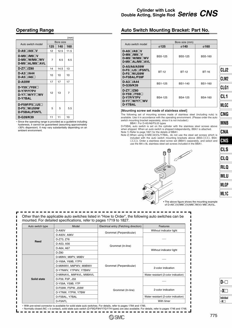
Bore sizeAuto switch model
D-A9�/A9�V
D-M9�/M9�VD-M9�W/M9�WVD-M9�AL/M9�AVL
12
7
14
12.5
6.5
14.5
11.5
6.5
13
125 140 160
(mm)
D-A3�/A44D-A5�/A6�D-A59W
D-Y59�/Y69�D-Y7P/Y7PVD-Y7�W/Y7�WVD-Y7BAL
D-F59F/F5�/J5�D-F5�W/J59WD-F5BAL/F5NTL
D-G39/K39
10
17
12
5
11
10
17
13
5
11
10
17
7
5.5
10
Auto Switch Mounting Bracket: Part No.
Bore size (mm)Auto switch model
BS5-125
ø125
BS5-125
ø140
BS5-160
ø160
D-A9�/A9�VD-M9�/M9�VD-M9�W/M9�WVD-M9�AL/M9�AVL
D-A5/A6/A59WD-F5�/J5�/F5NTLD-F5�W/J59WD-F5BAL/F59F
D-A3�/A44D-G39/K39
BT-12
BS4-125 BS4-125 BS4-160
BT-12 BT-16
BS1-125 BS1-140 BS1-160
[Mounting screw set made of stainless steel]The following set of mounting screws made of stainless steel (including nuts) is available. Use it in accordance with the operating environment. (Please order the auto switch mounting bracket separately, since it is not included.)
BBA1: For D-A5/A6/F5/J5 typesD-F5BAL auto switch is set on the cylinder with the stainless steel screws above when shipped. When an auto switch is shipped independently, BBA1 is attached.Note 1) Refer to page 1821 for the details of BBA1.Note 2) When using D-M9�A(V)L/Y7BAL, do not use the steel set screws which is
included with the auto switch mounting brackets above (BS5-���, BS4-���). Order a stainless steel screw set (BBA1) separately, and select and use the M4 x 8L stainless steel set screws included in the BBA1.
∗ With pre-wired connector is available for solid state auto switches. For details, refer to pages 1784 and 1785. ∗ Normally closed (NC = b contact), solid state auto switch (D-F9G/F9H/Y7G/Y7H types) are also available. For details, refer to pages 1746 and 1748.
D-A90V
D-A93V, A96V
D-Z73, Z76
D-A53, A56
D-A64, A67
D-Z80
D-M9NV, M9PV, M9BV
D-Y69A, Y69B, Y7PV
D-M9NWV, M9PWV, M9BWV
D-Y7NWV, Y7PWV, Y7BWV
D-M9NAVL, M9PAVL, M9BAVL
D-F59, F5P, J59
D-Y59A, Y59B, Y7P
D-F59W, F5PW, J59W
D-Y7NW, Y7PW, Y7BW
D-F5BAL, Y7BAL
D-F5NTL
Without indicator light
Without indicator light
2-color indication
Water resistant (2-color indication)
Water resistant (2-color indication)
With timer
2-color indication
Grommet (Perpendicular)
Grommet (In-line)
Grommet (In-line)
Grommet (Perpendicular)
Other than the applicable auto switches listed in “How to Order”, the following auto switches can be mounted. For detailed specifications, refer to pages 1719 to 1827.
Reed
Solid state
D-Z7�/Z80D-Y59�/Y69�D-Y7P/Y7PVD-Y7�W/Y7�WVD-Y7BAL
D-Z7�/Z80
Operating Range
∗ Since the operating range is provided as a guideline including hysteresis, it cannot be guaranteed (assuming approximately ±30% dispersion). It may vary substantially depending on an ambient environment.
• The above figure shows the mounting example of D-A9�(V)/M9�(V)/M9�W(V)/ M9�A(V)L.
775
Series CNSCylinder with LockDouble Acting, Single Rod
Auto switch type Model FeaturesElectrical entry (Fetching direction)
CLJ2
CLM2
CLG1
CL1
MLGC
CNG
MNB
CNA
CNS
CLS
CLQ
RLQ
MLU
MLGP
ML1C
Individual-X�
D-�
-X�
P0757-P0838-E.qxd 08.11.17 3:05 PM Page 775
Amount of overrun
Stop signal
776
Series CNSSpecific Product Precautions 1Be sure to read before handling. Refer to front matters 42 and 43 for Safety Instructions and pages 3 to 11 for Actuator and Auto Switch Precautions.
Design of Equipment and Machinery
Warning1. Construct so that the human body will not come
into direct contact with driven objects or the moving parts of the cylinders with lock. Devise a safe structure by attaching protective covers that prevent direct contact with the human body, or in cases where there is a danger of contact, provide sensors or other devices to perform an emergency stop, etc., before contact occurs.
2. Use a balance circuit, taking cylinder lurching into consideration. In cases such as an intermediate stop, where a lock is operated at a desired position within the stroke and air pressure is applied from only one side of the cylinder, the piston will lurch at high speed when the lock is released. In such situations, there is a danger of causing human injury by having hands or feet, etc. caught, and also a danger for causing damage to the equipment. In order to prevent this lurching, a balance circuit such as the recommended pneumatic circuits (page 777) should be used.
Selection
Warning1. When in the locked state, do not apply a load
accompanied by an impact shock, strong vibration or turning force, etc. Use caution, because an external action such as an impacting load, strong vibration or turning force, may damage the locking mechanism or reduce its life.
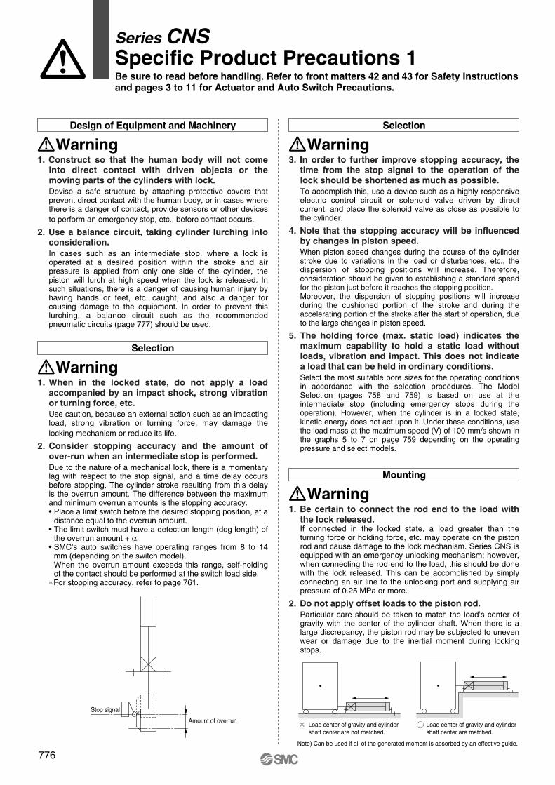
2. Consider stopping accuracy and the amount of over-run when an intermediate stop is performed. Due to the nature of a mechanical lock, there is a momentary lag with respect to the stop signal, and a time delay occurs before stopping. The cylinder stroke resulting from this delay is the overrun amount. The difference between the maximum and minimum overrun amounts is the stopping accuracy.• Place a limit switch before the desired stopping position, at a
distance equal to the overrun amount.• The limit switch must have a detection length (dog length) of
the overrun amount + α.• SMC’s auto switches have operating ranges from 8 to 14
mm (depending on the switch model).When the overrun amount exceeds this range, self-holding of the contact should be performed at the switch load side.
∗ For stopping accuracy, refer to page 761.
Selection
Warning3. In order to further improve stopping accuracy, the
time from the stop signal to the operation of the lock should be shortened as much as possible. To accomplish this, use a device such as a highly responsive electric control circuit or solenoid valve driven by direct current, and place the solenoid valve as close as possible to the cylinder.
4. Note that the stopping accuracy will be influenced by changes in piston speed.When piston speed changes during the course of the cylinder stroke due to variations in the load or disturbances, etc., the dispersion of stopping positions will increase. Therefore, consideration should be given to establishing a standard speed for the piston just before it reaches the stopping position.Moreover, the dispersion of stopping positions will increase during the cushioned portion of the stroke and during the accelerating portion of the stroke after the start of operation, due to the large changes in piston speed.
5. The holding force (max. static load) indicates the maximum capability to hold a static load without loads, vibration and impact. This does not indicate a load that can be held in ordinary conditions.Select the most suitable bore sizes for the operating conditions in accordance with the selection procedures. The Model Selection (pages 758 and 759) is based on use at the intermediate stop (including emergency stops during the operation). However, when the cylinder is in a locked state, kinetic energy does not act upon it. Under these conditions, use the load mass at the maximum speed (V) of 100 mm/s shown in the graphs 5 to 7 on page 759 depending on the operating pressure and select models.
Mounting
Warning1. Be certain to connect the rod end to the load with
the lock released. If connected in the locked state, a load greater than the turning force or holding force, etc. may operate on the piston rod and cause damage to the lock mechanism. Series CNS is equipped with an emergency unlocking mechanism; however, when connecting the rod end to the load, this should be done with the lock released. This can be accomplished by simply connecting an air line to the unlocking port and supplying air pressure of 0.25 MPa or more.
2. Do not apply offset loads to the piston rod.Particular care should be taken to match the load’s center of gravity with the center of the cylinder shaft. When there is a large discrepancy, the piston rod may be subjected to uneven wear or damage due to the inertial moment during locking stops.
Load center of gravity and cylinder shaft center are not matched.
Load center of gravity and cylinder shaft center are matched.
Note) Can be used if all of the generated moment is absorbed by an effective guide.
P0757-P0838-E.qxd 08.11.17 3:05 PM Page 776
777
Mounting
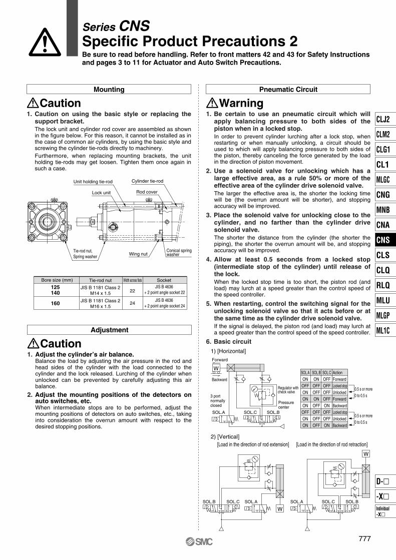
Caution1. Caution on using the basic style or replacing the
support bracket.The lock unit and cylinder rod cover are assembled as shown in the figure below. For this reason, it cannot be installed as in the case of common air cylinders, by using the basic style and screwing the cylinder tie-rods directly to machinery.Furthermore, when replacing mounting brackets, the unit holding tie-rods may get loosen. Tighten them once again in such a case.
Pneumatic Circuit
Warning1. Be certain to use an pneumatic circuit which will
apply balancing pressure to both sides of the piston when in a locked stop. In order to prevent cylinder lurching after a lock stop, when restarting or when manually unlocking, a circuit should be used to which will apply balancing pressure to both sides of the piston, thereby canceling the force generated by the load in the direction of piston movement.
2. Use a solenoid valve for unlocking which has a large effective area, as a rule 50% or more of the effective area of the cylinder drive solenoid valve.The larger the effective area is, the shorter the locking time will be (the overrun amount will be shorter), and stopping accuracy will be improved.
3. Place the solenoid valve for unlocking close to the cylinder, and no farther than the cylinder drive solenoid valve.The shorter the distance from the cylinder (the shorter the piping), the shorter the overrun amount will be, and stopping accuracy will be improved.
4. Allow at least 0.5 seconds from a locked stop (intermediate stop of the cylinder) until release of the lock.When the locked stop time is too short, the piston rod (and load) may lurch at a speed greater than the control speed of the speed controller.
5. When restarting, control the switching signal for the unlocking solenoid valve so that it acts before or at the same time as the cylinder drive solenoid valve.If the signal is delayed, the piston rod (and load) may lurch at a speed greater than the control speed of the speed controller.
6. Basic circuit
Lock unit
Wing nutConical springwasher
Rod cover
Cylinder tie-rodUnit holding tie-rod
Tie-rod nut,Spring washer
JIS B 1181 Class 2M14 x 1.5
JIS B 4636 + 2 point angle socket 22
JIS B 4636 + 2 point angle socket 24
Bore size (mm)
125140
160
Tie-rod nut SocketWidth across flats
22
24JIS B 1181 Class 2M16 x 1.5
Adjustment
Caution1. Adjust the cylinder’s air balance.
Balance the load by adjusting the air pressure in the rod and head sides of the cylinder with the load connected to the cylinder and the lock released. Lurching of the cylinder when unlocked can be prevented by carefully adjusting this air balance.
2. Adjust the mounting positions of the detectors on auto switches, etc. When intermediate stops are to be performed, adjust the mounting positions of detectors on auto switches, etc., taking into consideration the overrun amount with respect to the desired stopping positions.
1) [Horizontal]
Forward
Backward
3 portnormallyclosed
SOL.A SOL.C SOL.B
Pressurecenter
Regulator with check valve
WSOL.AONOFFONONONOFFONON
SOL.BONOFFOFFONOFFOFFOFFOFF
SOL.COFFOFFOFFOFFONOFFOFFON
ActionForwardLocked stopUnlockedForwardBackwardLocked stopUnlockedBackward
0.5 s or more0 to 0.5 s
0.5 s or more0 to 0.5 s
2) [Vertical][Load in the direction of rod extension] [Load in the direction of rod retraction]
SOL.C SOL.BSOL.A
W
SOL.B SOL.C SOL.A
W
Series CNSSpecific Product Precautions 2Be sure to read before handling. Refer to front matters 42 and 43 for Safety Instructions and pages 3 to 11 for Actuator and Auto Switch Precautions.
CLJ2
CLM2
CLG1
CL1
MLGC
CNG
MNB
CNA
CNS
CLS
CLQ
RLQ
MLU
MLGP
ML1C
Individual-X�
D-�
-X�
P0757-P0838-E.qxd 08.11.17 3:05 PM Page 777
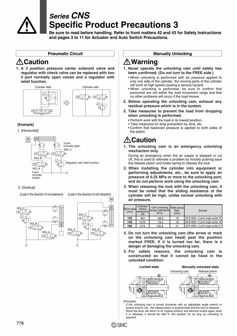
[Principle]If the unlocking cam is turned clockwise with an adjustable angle wrench or socket wrench, etc., the release piston is pushed back and the lock is released.Since the lever will return to its original position and become locked again when it is released, it should be held in this position for as long as unlocking is required.
778
Pneumatic Circuit
Caution1. A 3 position pressure center solenoid valve and
regulator with check valve can be replaced with two 3 port normally open valves and a regulator with relief function.
Manually Unlocking
Warning1. Never operate the unlocking cam until safety has
been confirmed. (Do not turn to the FREE side.) • When unlocking is performed with air pressure applied to
only one side of the cylinder, the moving parts of the cylinder will lurch at high speed causing a serious hazard.
• When unlocking is performed, be sure to confirm that personnel are not within the load movement range and that no other problems will occur if the load moves.
2. Before operating the unlocking cam, exhaust any residual pressure which is in the system.
3. Take measures to prevent the load from dropping when unlocking is performed. • Perform work with the load in its lowest position.• Take measures for drop prevention by strut, etc. • Confirm that balanced pressure is applied to both sides of
the piston.
Cylinder side Cylinder side
2. [Vertical]
[Load in the direction of rod extension] [Load in the direction of rod retraction]
[Example]
1. [Horizontal]
W3 portnormally openSOL.C
SOL.B
SOL.A3 portnormallyclosed
Regulator with relief function
SOL.B
SOL.C
SOL.A
W
SOL.C
SOL.A SOL.B
Caution1. The unlocking cam is an emergency unlocking
mechanism only. During an emergency when the air supply is stopped or cut off, this is used to alleviate a problem by forcibly pushing back the release piston and brake spring to release the lock.
2. When installing the cylinder into equipment or performing adjustments, etc., be sure to apply air pressure of 0.25 MPa or more to the unlocking port, and do not perform work using the unlocking cam.
3. When releasing the lock with the unlocking cam, it must be noted that the sliding resistance of the cylinder will be high, unlike normal unlocking with air pressure.
4. Do not turn the unlocking cam (the arrow or mark on the unlocking cam head) past the position marked FREE. If it is turned too far, there is a danger of damaging the unlocking cam.
5. For safety reasons, the unlocking cam is constructed so that it cannot be fixed in the unlocked condition.
Bore size(mm)
Cylindersliding
resistance(N)
Cam unlockingtorque (standard)
(N·m)
Width acrossflats (mm)
Socket
125140160
96112161579
161821
JIS B 4636 + 2 point angle socket 16JIS B 4636 + 2 point angle socket 18JIS B 4636 + 2 point angle socket 21
68.678.4
156.8
Locked state Manually unlocked stateRelease pistonUnlocking cam
Series CNSSpecific Product Precautions 3Be sure to read before handling. Refer to front matters 42 and 43 for Safety Instructions and pages 3 to 11 for Actuator and Auto Switch Precautions.
P0757-P0838-E.qxd 08.11.17 3:05 PM Page 778
Bore size (mm)
125140160
Lock unit part no.
CNS125D-UA
CNS140D-UA
CNS160D-UA
Maintenance
779
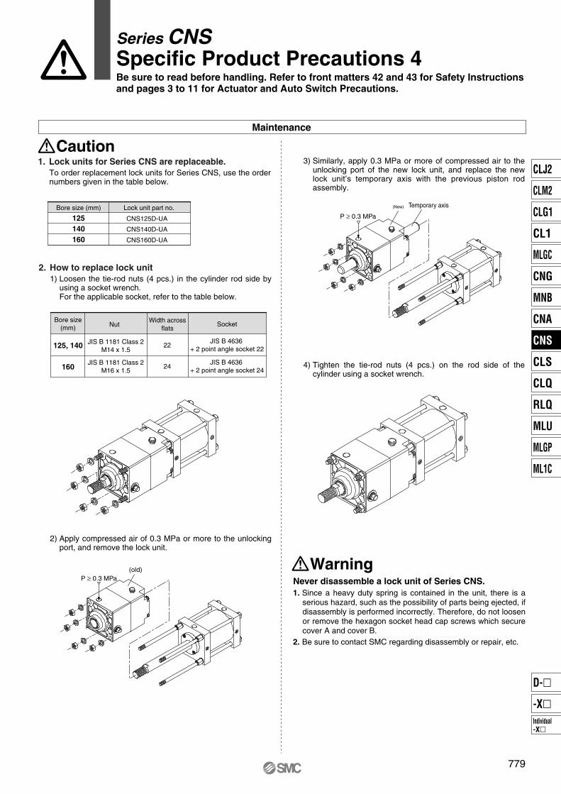
Caution1. Lock units for Series CNS are replaceable.
To order replacement lock units for Series CNS, use the order numbers given in the table below.
3) Similarly, apply 0.3 MPa or more of compressed air to the unlocking port of the new lock unit, and replace the new lock unit’s temporary axis with the previous piston rod assembly.
4) Tighten the tie-rod nuts (4 pcs.) on the rod side of the cylinder using a socket wrench.
2. How to replace lock unit 1) Loosen the tie-rod nuts (4 pcs.) in the cylinder rod side by
using a socket wrench. For the applicable socket, refer to the table below.
Bore size(mm)
125, 140
160
JIS B 1181 Class 2M14 x 1.5
JIS B 4636 + 2 point angle socket 22
JIS B 4636 + 2 point angle socket 24
JIS B 1181 Class 2M16 x 1.5
NutWidth across
flatsSocket
22
24
2) Apply compressed air of 0.3 MPa or more to the unlocking port, and remove the lock unit.
P ≥ 0.3 MPa(old)
P ≥ 0.3 MPa
Temporary axis(New)
1. Since a heavy duty spring is contained in the unit, there is a serious hazard, such as the possibility of parts being ejected, if disassembly is performed incorrectly. Therefore, do not loosen or remove the hexagon socket head cap screws which secure cover A and cover B.
2. Be sure to contact SMC regarding disassembly or repair, etc.
Never disassemble a lock unit of Series CNS.
Warning
Series CNSSpecific Product Precautions 4Be sure to read before handling. Refer to front matters 42 and 43 for Safety Instructions and pages 3 to 11 for Actuator and Auto Switch Precautions.
CLJ2
CLM2
CLG1
CL1
MLGC
CNG
MNB
CNA
CNS
CLS
CLQ
RLQ
MLU
MLGP
ML1C
Individual-X�
D-�
-X�
P0757-P0838-E.qxd 08.11.17 3:05 PM Page 779