SAFE M / M - cm-manufactory.comSkilled personnel who plan or de- ... 200Ω. Bis Kategorie 3; SIL2;...
9
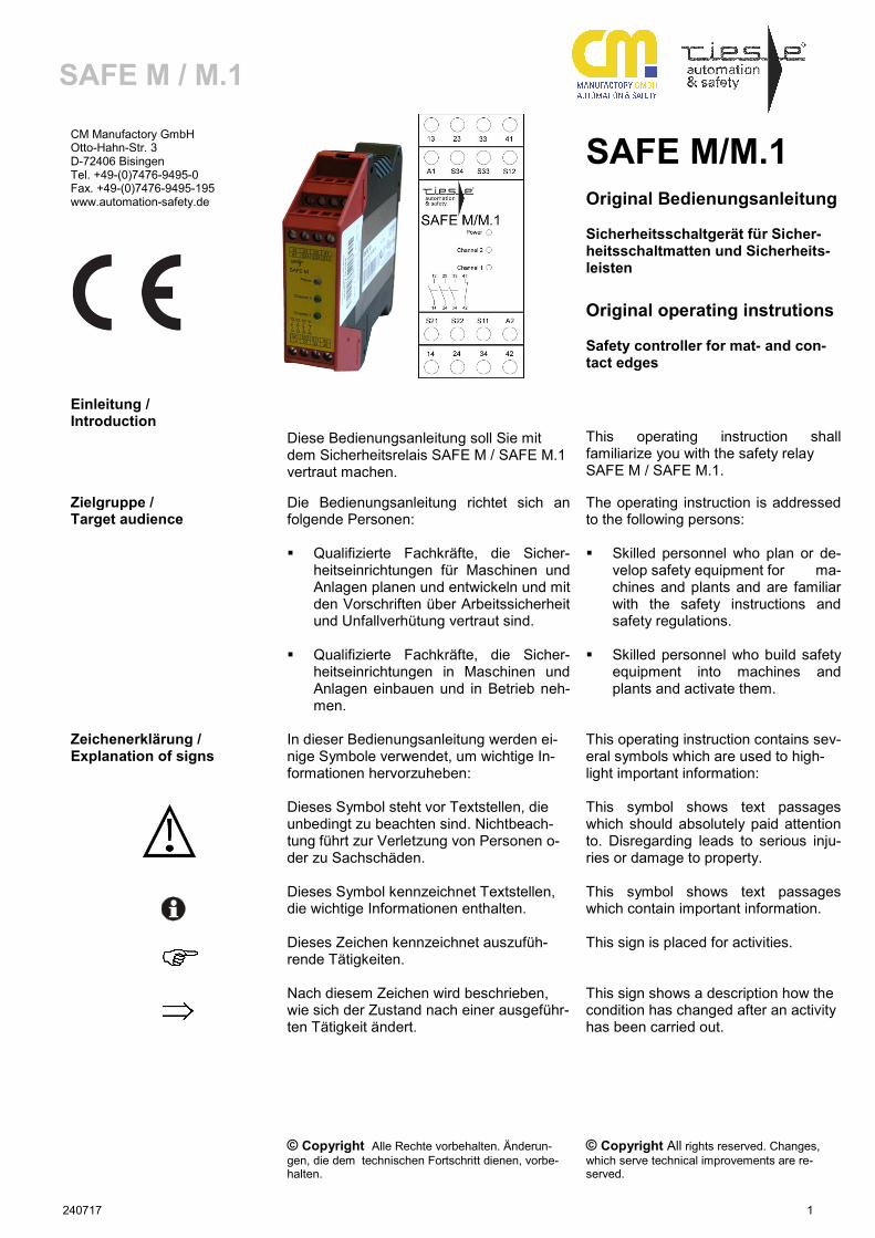
240717 1 SAFE M / M.1 CM Manufactory GmbH Otto-Hahn-Str. 3 D-72406 Bisingen Tel. +49-(0)7476-9495-0 Fax. +49-(0)7476-9495-195 www.automation-safety.de SAFE M/M.1 Original Bedienungsanleitung Sicherheitsschaltgerät für Sicher- heitsschaltmatten und Sicherheits- leisten Original operating instrutions Safety controller for mat- and con- tact edges Einleitung / Introduction Diese Bedienungsanleitung soll Sie mit dem Sicherheitsrelais SAFE M / SAFE M.1 vertraut machen. This operating instruction shall familiarize you with the safety relay SAFE M / SAFE M.1. Zielgruppe / Target audience Die Bedienungsanleitung richtet sich an folgende Personen: Qualifizierte Fachkräfte, die Sicher- heitseinrichtungen für Maschinen und Anlagen planen und entwickeln und mit den Vorschriften über Arbeitssicherheit und Unfallverhütung vertraut sind. Qualifizierte Fachkräfte, die Sicher- heitseinrichtungen in Maschinen und Anlagen einbauen und in Betrieb neh- men. The operating instruction is addressed to the following persons: Skilled personnel who plan or de- velop safety equipment for ma- chines and plants and are familiar with the safety instructions and safety regulations. Skilled personnel who build safety equipment into machines and plants and activate them. Zeichenerklärung / Explanation of signs In dieser Bedienungsanleitung werden ei- nige Symbole verwendet, um wichtige In- formationen hervorzuheben: This operating instruction contains sev- eral symbols which are used to high- light important information: Dieses Symbol steht vor Textstellen, die unbedingt zu beachten sind. Nichtbeach- tung führt zur Verletzung von Personen o- der zu Sachschäden. This symbol shows text passages which should absolutely paid attention to. Disregarding leads to serious inju- ries or damage to property. Dieses Symbol kennzeichnet Textstellen, die wichtige Informationen enthalten. This symbol shows text passages which contain important information. Dieses Zeichen kennzeichnet auszufüh- rende Tätigkeiten. This sign is placed for activities. Nach diesem Zeichen wird beschrieben, wie sich der Zustand nach einer ausgeführ- ten Tätigkeit ändert. © Copyright Alle Rechte vorbehalten. Änderun- gen, die dem technischen Fortschritt dienen, vorbe- halten. This sign shows a description how the condition has changed after an activity has been carried out. © Copyright All rights reserved. Changes, which serve technical improvements are re- served.
Transcript of SAFE M / M - cm-manufactory.comSkilled personnel who plan or de- ... 200Ω. Bis Kategorie 3; SIL2;...
240717 1
SAFE M / M.1
CM Manufactory GmbH Otto-Hahn-Str. 3 D-72406 Bisingen Tel. +49-(0)7476-9495-0 Fax. +49-(0)7476-9495-195 www.automation-safety.de
SAFE M/M.1
Original Bedienungsanleitung Sicherheitsschaltgerät für Sicher-heitsschaltmatten und Sicherheits-leisten
Original operating instrutions Safety controller for mat- and con-tact edges
Einleitung / Introduction
Diese Bedienungsanleitung soll Sie mit dem Sicherheitsrelais SAFE M / SAFE M.1 vertraut machen.
This operating instruction shall familiarize you with the safety relay SAFE M / SAFE M.1.
Zielgruppe / Target audience
Die Bedienungsanleitung richtet sich an folgende Personen: Qualifizierte Fachkräfte, die Sicher-
heitseinrichtungen für Maschinen und Anlagen planen und entwickeln und mit den Vorschriften über Arbeitssicherheit und Unfallverhütung vertraut sind.
Qualifizierte Fachkräfte, die Sicher-heitseinrichtungen in Maschinen und Anlagen einbauen und in Betrieb neh-men.
The operating instruction is addressed to the following persons: Skilled personnel who plan or de-
velop safety equipment for ma-chines and plants and are familiar with the safety instructions and safety regulations.
Skilled personnel who build safety
equipment into machines and plants and activate them.
Zeichenerklärung / Explanation of signs
In dieser Bedienungsanleitung werden ei-nige Symbole verwendet, um wichtige In-formationen hervorzuheben:
This operating instruction contains sev-eral symbols which are used to high-light important information:
Dieses Symbol steht vor Textstellen, die unbedingt zu beachten sind. Nichtbeach-tung führt zur Verletzung von Personen o-der zu Sachschäden.
This symbol shows text passages which should absolutely paid attention to. Disregarding leads to serious inju-ries or damage to property.
Dieses Symbol kennzeichnet Textstellen, die wichtige Informationen enthalten.
This symbol shows text passages which contain important information.
Dieses Zeichen kennzeichnet auszufüh-rende Tätigkeiten.
This sign is placed for activities.
Nach diesem Zeichen wird beschrieben, wie sich der Zustand nach einer ausgeführ-ten Tätigkeit ändert. © Copyright Alle Rechte vorbehalten. Änderun-gen, die dem technischen Fortschritt dienen, vorbe-halten.
This sign shows a description how the condition has changed after an activity has been carried out. © Copyright All rights reserved. Changes, which serve technical improvements are re-served.
240717 2
SAFE M / M.1
Sicherheitshinweise Safety indications
Bestimmungsgemäße Verwendung / Intended Application
Die Sicherheitsrelais SAFE M (ohne Über-wachung der Starttaste) und SAFE M.1 (mit Überwachung der Start-Taste) sind be-stimmt für den Einsatz in: Ein- oder Zweikanalige Schaltungs-
technik für Sicherheitsmatten. Ein- oder Zweikanalige Schaltungs-
technik für Sicherheitsleisten.
The safety relays SAFE M (for auto-matic start) and SAFE M.1 (with control of the start button) are intended for the use with: Single or dual- channel capability
for safety mats. Single or dual- channel capability
for safety contact edges.
Personen- und Sachschutz sind nicht mehr gewährleistet, wenn das Sicherheitsrelais nicht entsprechend seiner bestimmungsge-mäßen Verwendung eingesetzt wird.
Operator and object protection is only guaranteed, if the safety relay is used according to its intended purpose.
Zu Ihrer Sicherheit / For your safety
Beachten Sie unbedingt die folgenden Punkte:
Please pay attention to the following points:
Das Gerät darf nur unter Beachtung die-ser Bedienungsanleitung von Fach-personal installiert und in Betrieb ge-nommen werden, das mit den gelten-den Vorschriften über Arbeitssicherheit und Unfallverhütung vertraut ist. Elektri-sche Arbeiten dürfen nur von Elektro-fachkräften durchgeführt werden.
Beachten Sie die jeweils gültigen Vor-schriften, insbesondere hinsichtlich der Schutzmaßnahmen.
Reparaturen, insbesondere das Öffnen des Gehäuses, dürfen nur vom Herstel-ler oder einer von ihm beauftragten Per-son vorgenommen werden. Ansonsten erlischt jegliche Gewährleistung.
Vermeiden Sie mechanische Erschütte-rungen beim Transport oder im Betrieb; Stöße größer 5g / 33Hz können zur Be-schädigung des Gerätes führen.
Montieren Sie das Gerät in einem staub- und feuchtigkeitsgeschützten Gehäuse; Staub und Feuchtigkeit kön-nen zu Funktionsstörungen führen.
Sorgen Sie für eine ausreichende Schutzbeschaltung bei kapazitiven und induktiven Lasten an den Ausgangs-kontakten.
The device has to be wired and op-erated by specialized staff, who are familiar with this instruction and the current regulations for safety at work and accident prevention. Working on electrical equipment is only allowed by specialized staff.
Pay attention to valid regulations,
particularly in reference to pre-ventative measures.
Any repairs have to be done by the manufacturer or a person which is authorized by the manufacturer. It is prohibited to open the device or implement unauthorized changes, otherwise any warranty expires.
Avoid mechanical vibrations more than 5g/33 Hz while transportation and during operation.
The unit should be panel mounted in an enclosure rated IP 54 or bet-ter. Dust and dampness could lead to malfunction.
Adequate fuse protection must be provided on all output contacts with capacitive and inductive loads.
240717 3
SAFE M / M.1
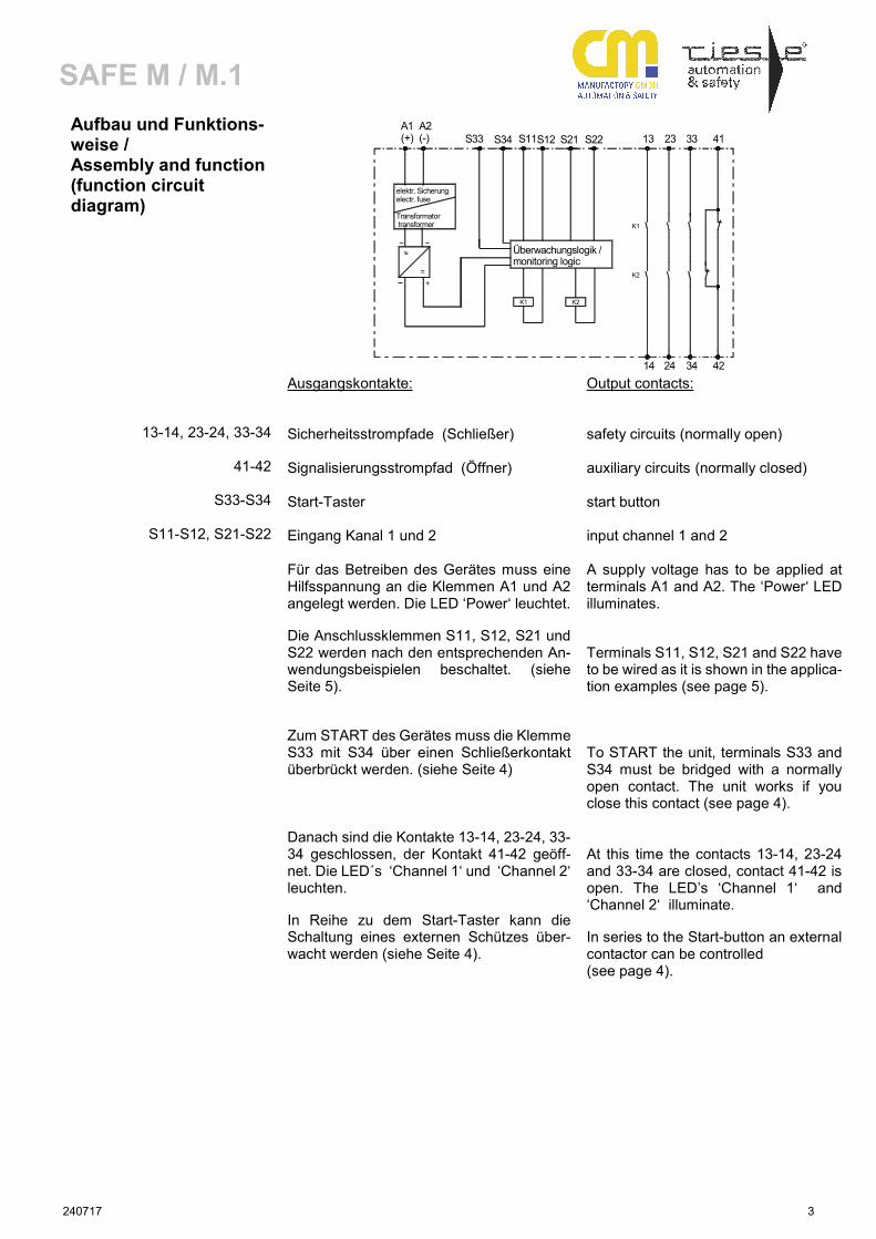
Aufbau und Funktions-weise / Assembly and function (function circuit diagram)
Ausgangskontakte:
Output contacts:
13-14, 23-24, 33-34
41-42
S33-S34
S11-S12, S21-S22
Sicherheitsstrompfade (Schließer) Signalisierungsstrompfad (Öffner) Start-Taster Eingang Kanal 1 und 2
safety circuits (normally open) auxiliary circuits (normally closed) start button input channel 1 and 2
Für das Betreiben des Gerätes muss eine Hilfsspannung an die Klemmen A1 und A2 angelegt werden. Die LED ‘Power‘ leuchtet. Die Anschlussklemmen S11, S12, S21 und S22 werden nach den entsprechenden An-wendungsbeispielen beschaltet. (siehe Seite 5). Zum START des Gerätes muss die Klemme S33 mit S34 über einen Schließerkontakt überbrückt werden. (siehe Seite 4) Danach sind die Kontakte 13-14, 23-24, 33-34 geschlossen, der Kontakt 41-42 geöff-net. Die LED´s ‘Channel 1‘ und ‘Channel 2‘ leuchten. In Reihe zu dem Start-Taster kann die Schaltung eines externen Schützes über-wacht werden (siehe Seite 4).
A supply voltage has to be applied at terminals A1 and A2. The ‘Power‘ LED illuminates. Terminals S11, S12, S21 and S22 have to be wired as it is shown in the applica-tion examples (see page 5). To START the unit, terminals S33 and S34 must be bridged with a normally open contact. The unit works if you close this contact (see page 4). At this time the contacts 13-14, 23-24 and 33-34 are closed, contact 41-42 is open. The LED’s ‘Channel 1‘ and ‘Channel 2‘ illuminate. In series to the Start-button an external contactor can be controlled (see page 4).
S12
Überwachungslogik /monitoring logic
~ ~
~~
+
=
K1
elektr. Sicherung electr. fuse Transformator transformer
A1(+)
A2(-) S34S33 S11
14
K2
K2
3424 42
13
K1
S22S21 3323 41
240717 4
SAFE M / M.1
Mechanische Montage / Mechanical mounting
Montage und Inbetriebnahme
Mounting and opening
Für eine sichere Funktion muss das Si-cherheitsrelais in ein staub- und feuch-tigkeitsgeschütztes Gehäuse eingebaut werden (IP54).
The unit should be panel mounted in an enclosure rated at IP 54 or better. Dust and dampness could lead to malfunc-tion.
Montieren Sie das Not-Halt Sicherheitsrelais auf eine Normschiene.
There is a notch on the rear of the unit for DIN-Rail attachment.
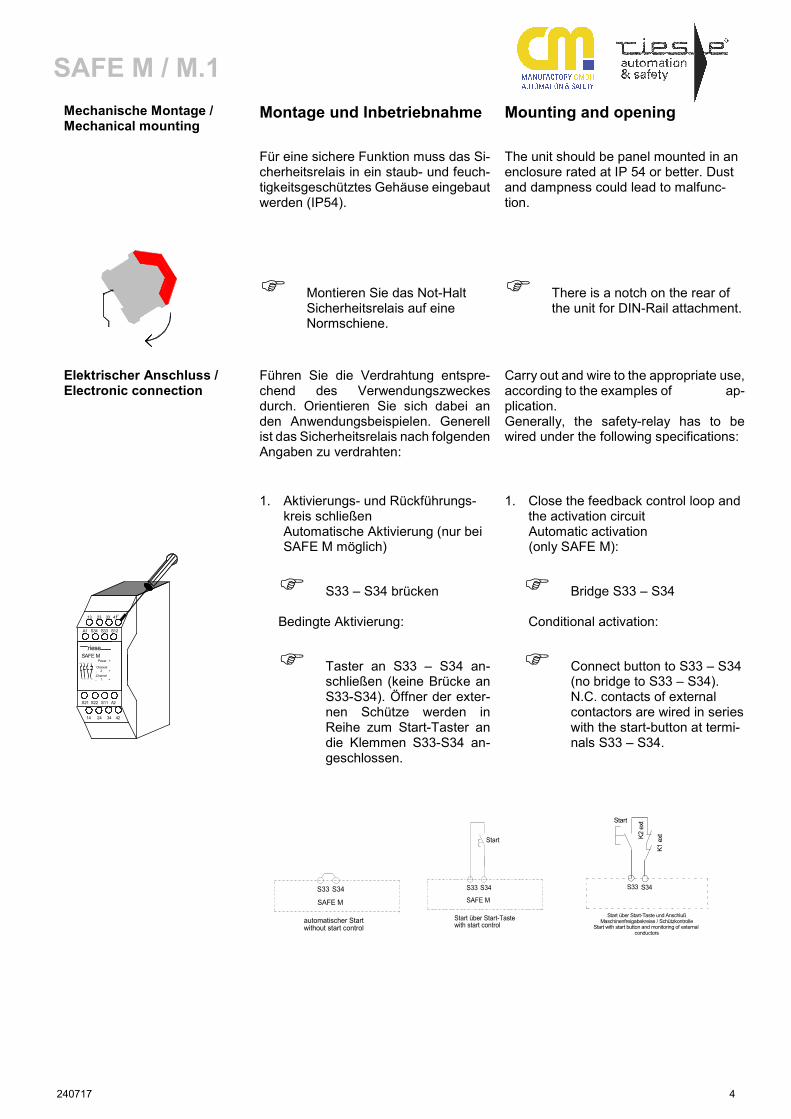
Elektrischer Anschluss / Electronic connection
Führen Sie die Verdrahtung entspre-chend des Verwendungszweckes durch. Orientieren Sie sich dabei an den Anwendungsbeispielen. Generell ist das Sicherheitsrelais nach folgenden Angaben zu verdrahten:
Carry out and wire to the appropriate use, according to the examples of ap-plication. Generally, the safety-relay has to be wired under the following specifications:
1. Aktivierungs- und Rückführungs-kreis schließen Automatische Aktivierung (nur bei SAFE M möglich)
S33 – S34 brücken Bedingte Aktivierung:
Taster an S33 – S34 an-schließen (keine Brücke an S33-S34). Öffner der exter-nen Schütze werden in Reihe zum Start-Taster an die Klemmen S33-S34 an-geschlossen.
1. Close the feedback control loop and the activation circuit Automatic activation (only SAFE M):
Bridge S33 – S34 Conditional activation:
Connect button to S33 – S34 (no bridge to S33 – S34). N.C. contacts of external contactors are wired in series with the start-button at termi-nals S33 – S34.
Power +
S21 S22 S11 A2
14 24 34 42
13 23 33 41
14 24 34 42
Channel 1 +
Channel 2 +
rieseSAFE M
A1 S34 S33 S12
13 23 33 41
S34
automatischer Startwithout start control
SAFE M
S33 S34
Start über Start-Tastewith start control
SAFE M
S33
Start
S34
Start über Start-Taste und AnschlußMaschinenfreigabekreise / Schützkontrolle
Start with start button and monitoring of external conductors
S33
Start
K2
ext
K1
ext
240717 5
SAFE M / M.1
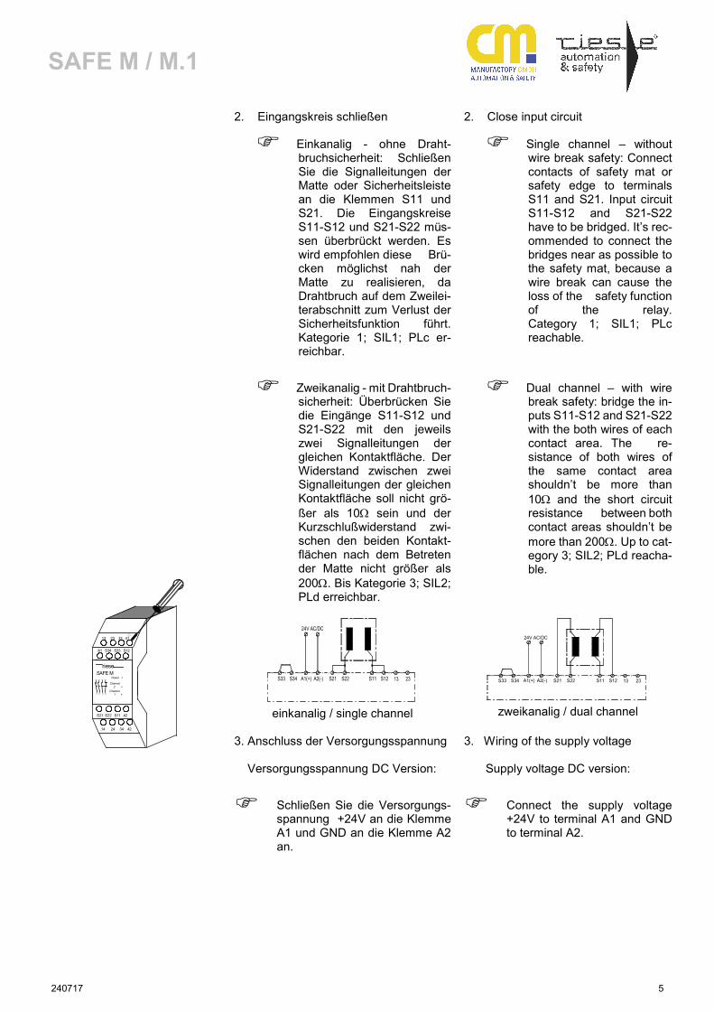
2. Eingangskreis schließen 2. Close input circuit
Einkanalig - ohne Draht-bruchsicherheit: Schließen Sie die Signalleitungen der Matte oder Sicherheitsleiste an die Klemmen S11 und S21. Die Eingangskreise S11-S12 und S21-S22 müs-sen überbrückt werden. Es wird empfohlen diese Brü-cken möglichst nah der Matte zu realisieren, da Drahtbruch auf dem Zweilei-terabschnitt zum Verlust der Sicherheitsfunktion führt. Kategorie 1; SIL1; PLc er-reichbar.
Single channel – without wire break safety: Connect contacts of safety mat or safety edge to terminals S11 and S21. Input circuit S11-S12 and S21-S22 have to be bridged. It’s rec-ommended to connect the bridges near as possible to the safety mat, because a wire break can cause the loss of the safety function of the relay. Category 1; SIL1; PLc reachable.
Zweikanalig - mit Drahtbruch-sicherheit: Überbrücken Sie die Eingänge S11-S12 und S21-S22 mit den jeweils zwei Signalleitungen der gleichen Kontaktfläche. Der Widerstand zwischen zwei Signalleitungen der gleichen Kontaktfläche soll nicht grö-ßer als 10Ω sein und der Kurzschlußwiderstand zwi-schen den beiden Kontakt-flächen nach dem Betreten der Matte nicht größer als 200Ω. Bis Kategorie 3; SIL2; PLd erreichbar.
Dual channel – with wire break safety: bridge the in-puts S11-S12 and S21-S22 with the both wires of each contact area. The re-sistance of both wires of the same contact area shouldn’t be more than 10Ω and the short circuit resistance between both contact areas shouldn’t be more than 200Ω. Up to cat-egory 3; SIL2; PLd reacha-ble.
A1(+)S33 S34 A2(-) S21
24V AC/DC
S11S22 23S12 13
einkanalig / single channel
A1(+)S33 S34 A2(-) S21
24V AC/DC
S11S22 23S12 13
zweikanalig / dual channel
3. Anschluss der Versorgungsspannung Versorgungsspannung DC Version:
Schließen Sie die Versorgungs-spannung +24V an die Klemme A1 und GND an die Klemme A2 an.
3. Wiring of the supply voltage Supply voltage DC version:
Connect the supply voltage +24V to terminal A1 and GND to terminal A2.
Power +
S21 S22 S11 A2
14 24 34 42
13 23 33 41
14 24 34 42
Channel 1 +
Channel 2 +
rieseSAFE M
A1 S34 S33 S12
13 23 33 41
240717 6
SAFE M / M.1
Versorgungsspannung AC Version:
Schließen Sie die Versorgungs-spannung an die Klemmen A1 und A2 an.
Schließen Sie den Schutzleiter an die Klemme PE an. Die Ver-bindung muss lösbar sein. Bei der Gerätevariante 24 V AC/DC darf der Schutzleiter nicht ange-schlossen werden.
Supply voltage AC version:
Connect the supply voltage to terminals A1 and A2.
Connect the protective conduc-tor to the terminal PE. The con-nection has to be unlockable. It is not allowed to connect the protective conductor to PE when using device type 24V AC/DC.
Beachten Sie unbedingt die maximalen Leitungslängen!
Please note the maximum lengths of cables.
Wartung und Reparatur
Maintenance and repair
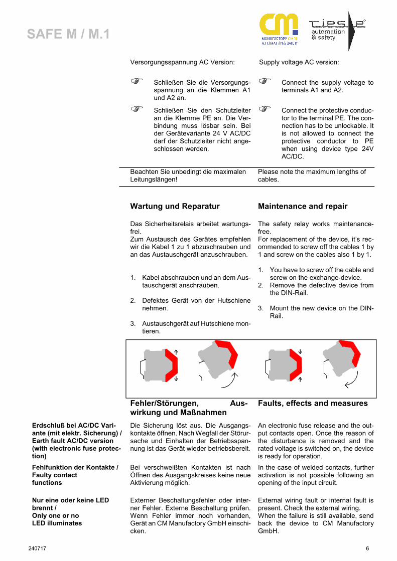
Das Sicherheitsrelais arbeitet wartungs-frei. Zum Austausch des Gerätes empfehlen wir die Kabel 1 zu 1 abzuschrauben und an das Austauschgerät anzuschrauben.
1. Kabel abschrauben und an dem Aus-tauschgerät anschrauben.
2. Defektes Gerät von der Hutschiene
nehmen. 3. Austauschgerät auf Hutschiene mon-
tieren.
The safety relay works maintenance- free. For replacement of the device, it’s rec-ommended to screw off the cables 1 by 1 and screw on the cables also 1 by 1.
1. You have to screw off the cable and
screw on the exchange-device. 2. Remove the defective device from
the DIN-Rail. 3. Mount the new device on the DIN-
Rail.
Fehler/Störungen, Aus-wirkung und Maßnahmen
Faults, effects and measures
Erdschluß bei AC/DC Vari-ante (mit elektr. Sicherung) / Earth fault AC/DC version (with electronic fuse protec-tion)
Die Sicherung löst aus. Die Ausgangs-kontakte öffnen. Nach Wegfall der Störur-sache und Einhalten der Betriebsspan-nung ist das Gerät wieder betriebsbereit.
An electronic fuse release and the out-put contacts open. Once the reason of the disturbance is removed and the rated voltage is switched on, the device is ready for operation.
Fehlfunktion der Kontakte / Faulty contact functions
Bei verschweißten Kontakten ist nach Öffnen des Ausgangskreises keine neue Aktivierung möglich.
In the case of welded contacts, further activation is not possible following an opening of the input circuit.
Nur eine oder keine LED brennt / Only one or no LED illuminates
Externer Beschaltungsfehler oder inter-ner Fehler. Externe Beschaltung prüfen. Wenn Fehler immer noch vorhanden, Gerät an CM Manufactory GmbH einschi-cken.
External wiring fault or internal fault is present. Check the external wiring. When the failure is still available, send back the device to CM Manufactory GmbH.
240717 7
SAFE M / M.1
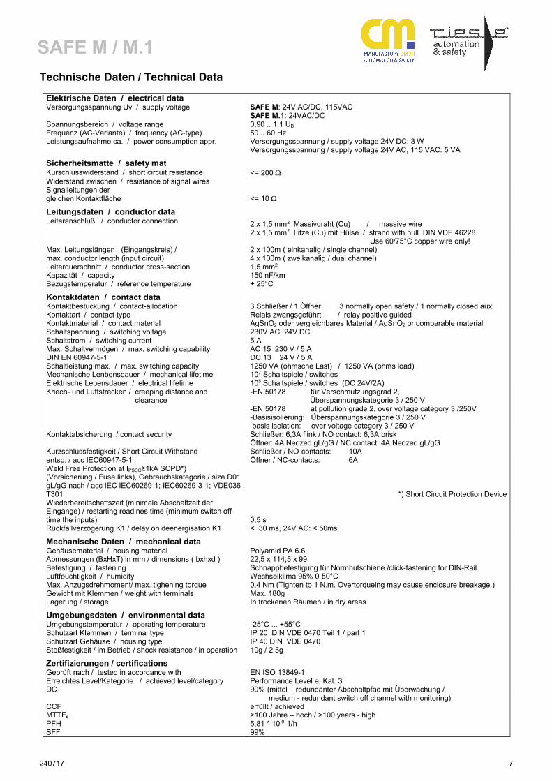
Technische Daten / Technical Data
Elektrische Daten / electrical data Versorgungsspannung Uv / supply voltage SAFE M: 24V AC/DC, 115VAC
SAFE M.1: 24VAC/DC Spannungsbereich / voltage range 0,90 .. 1,1 UB Frequenz (AC-Variante) / frequency (AC-type) 50 .. 60 Hz Leistungsaufnahme ca. / power consumption appr. Versorgungsspannung / supply voltage 24V DC: 3 W
Versorgungsspannung / supply voltage 24V AC, 115 VAC: 5 VA
Sicherheitsmatte / safety mat Kurschlusswiderstand / short circuit resistance <= 200 Ω Widerstand zwischen / resistance of signal wires Signalleitungen der gleichen Kontaktfläche <= 10 Ω
Leitungsdaten / conductor data Leiteranschluß / conductor connection 2 x 1,5 mm2 Massivdraht (Cu) / massive wire
2 x 1,5 mm2 Litze (Cu) mit Hülse / strand with hull DIN VDE 46228 Use 60/75°C copper wire only!
Max. Leitungslängen (Eingangskreis) / max. conductor length (input circuit)
2 x 100m ( einkanalig / single channel) 4 x 100m ( zweikanalig / dual channel)
Leiterquerschnitt / conductor cross-section 1,5 mm2 Kapazität / capacity 150 nF/km Bezugstemperatur / reference temperature + 25°C
Kontaktdaten / contact data Kontaktbestückung / contact-allocation 3 Schließer / 1 Öffner 3 normally open safety / 1 normally closed aux Kontaktart / contact type Relais zwangsgeführt / relay positive guided Kontaktmaterial / contact material AgSnO2 oder vergleichbares Material / AgSnO2 or comparable material Schaltspannung / switching voltage 230V AC, 24V DC Schaltstrom / switching current 5 A Max. Schaltvermögen / max. switching capability DIN EN 60947-5-1
AC 15 230 V / 5 A DC 13 24 V / 5 A
Schaltleistung max. / max. switching capacity 1250 VA (ohmsche Last) / 1250 VA (ohms load) Mechanische Lenbensdauer / mechanical lifetime 107 Schaltspiele / switches Elektrische Lebensdauer / electrical lifetime 105 Schaltspiele / switches (DC 24V/2A) Kriech- und Luftstrecken / creeping distance and clearance
-EN 50178 für Verschmutzungsgrad 2, Überspannungskategorie 3 / 250 V -EN 50178 at pollution grade 2, over voltage category 3 /250V -Basisisolierung: Überspannungskategorie 3 / 250 V basis isolation: over voltage category 3 / 250 V
Kontaktabsicherung / contact security Schließer: 6,3A flink / NO contact: 6,3A brisk Öffner: 4A Neozed gL/gG / NC contact: 4A Neozed gL/gG
Kurzschlussfestigkeit / Short Circuit Withstand entsp. / acc IEC60947-5-1 Weld Free Protection at IPSCC≥1kA SCPD*) (Vorsicherung / Fuse links), Gebrauchskategorie / size D01 gL/gG nach / acc IEC IEC60269-1; IEC60269-3-1; VDE036-T301
Schließer / NO-contacts: 10A Öffner / NC-contacts: 6A
*) Short Circuit Protection Device Wiederbereitschaftszeit (minimale Abschaltzeit der Eingänge) / restarting readines time (minimum switch off time the inputs) 0,5 s Rückfallverzögerung K1 / delay on deenergisation K1 < 30 ms, 24V AC: < 50ms
Mechanische Daten / mechanical data Gehäusematerial / housing material Polyamid PA 6.6 Abmessungen (BxHxT) in mm / dimensions ( bxhxd ) 22,5 x 114,5 x 99 Befestigung / fastening Schnappbefestigung für Normhutschiene /click-fastening for DIN-Rail Luftfeuchtigkeit / humidity Wechselklima 95% 0-50°C Max. Anzugsdrehmoment/ max. tighening torque 0,4 Nm (Tighten to 1 N.m. Overtorqueing may cause enclosure breakage.) Gewicht mit Klemmen / weight with terminals Max. 180g Lagerung / storage In trockenen Räumen / in dry areas
Umgebungsdaten / environmental data Umgebungstemperatur / operating temperature -25°C ... +55°C Schutzart Klemmen / terminal type IP 20 DIN VDE 0470 Teil 1 / part 1 Schutzart Gehäuse / housing type IP 40 DIN VDE 0470 Stoßfestigkeit / im Betrieb / shock resistance / in operation 10g / 2,5g
Zertifizierungen / certifications Geprüft nach / tested in accordance with EN ISO 13849-1 Erreichtes Level/Kategorie / achieved level/category Performance Level e, Kat. 3 DC 90% (mittel – redundanter Abschaltpfad mit Überwachung /
medium - redundant switch off channel with monitoring) CCF erfüllt / achieved MTTFd >100 Jahre – hoch / >100 years - high PFH 5,81 * 10-9 1/h SFF 99%
240717 8
SAFE M / M.1
Gerätevarianten / Devices
Name / Name: Spannung / Voltage: Artikel-Nummer. / Article number:
SAFE M 24 V AC / DC 45029 AR.9647.2000
SAFE M 115V AC 45240 AR.9647.4000
SAFE M.1 24 V AC / DC 45034 AR.9648.2000