Compact and lightweight 1.5 μm lidar with a multi-mode ...
5
REVIEW OF SCIENTIFIC INSTRUMENTS 89, 103106 (2018) Compact and lightweight 1.5 μm lidar with a multi-mode fiber coupling free-running InGaAs/InP single-photon detector Chao Yu, 1,2,a) Jiawei Qiu, 3,a) Haiyun Xia, 2,3,b) Xiankang Dou, 3 Jun Zhang, 1,2,c) and Jian-Wei Pan 1,2 1 Hefei National Laboratory for Physical Sciences at Microscale and Department of Modern Physics, University of Science and Technology of China, Hefei, Anhui 230026, China 2 CAS Center for Excellence in Quantum Information and Quantum Physics, University of Science and Technology of China, Hefei, Anhui 230026, China 3 CAS Key Laboratory of Geospace Environment, University of Science and Technology of China, Hefei, Anhui 230026, China (Received 7 July 2018; accepted 27 September 2018; published online 15 October 2018) We present a compact and lightweight 1.5 μm lidar using a free-running single-photon detector (SPD) based on a multi-mode fiber (MMF) coupling InGaAs/InP negative feedback avalanche diode. The ultimate light detection sensitivity of SPD highly reduces the power requirement of the laser, whilst the enhanced collection efficiency due to MMF coupling significantly reduces the volume and weight of telescopes. We develop a specific algorithm for the corrections of errors caused by the SPD and erbium-doped fiber amplifier to extract accurate backscattering signals. We also perform a compar- ison between single-mode fiber (SMF) coupling and MMF coupling in the lidar receiver, and the results show that the collection efficiency with MMF coupling is five times higher than that with SMF coupling. In order to validate the functionality, we use the lidar system for the application of cloud detection. The lidar system exhibits the ability to detect both the cloud base height and the thickness of multi-layer clouds to an altitude of 12 km with a temporal resolution of 1 s and a spatial resolution of 15 m. Due to the advantages of compactness and lightweight, our lidar system can be installed on unmanned aerial vehicles for wide applications in practice. Published by AIP Publishing. https://doi.org/10.1063/1.5047472 I. INTRODUCTION Aerosols are the extended colloidal dispersion of solid or liquid particles in a gaseous medium such as smoke, fog, sea salt, soil dust, and combustion products. The occurrence, res- idence time, and physical and chemical properties of aerosols vary fast in space and time. For instance, clouds are essen- tially aerosols consisting of minute liquid droplets and frozen crystals suspended in the atmosphere, which fundamentally influence weather, air travel safety, sunlight illumination, and climate. Lidar (light detection and ranging), including coherent lidar and direct detection lidar, provides an effective tech- nology to detect aerosols with high resolution. Compared with coherent lidar, direct detection lidar can directly detect the intensity of backscattering signals with simple system design and data processing, which is well suited for cloud and aerosol detections. Commercial direct detection lidars widely use lasers at wavelengths of 532 nm, 910 nm, and 1064 nm 1,2 due to the fact that mature silicon avalanche photodiodes can be used at these wavelengths. Since 1.5 μm laser has advantages of eye-safe, low atmo- spheric attenuation, and low solar background energy, such wavelength is also an ideal candidate for lidar applications. The performance in terms of the detection range of the 1.5 μm direct detection lidar is considerably limited by the detection a) C. Yu and J. Qiu contributed equally to this work. b) Electronic mail: [email protected] c) Electronic mail: [email protected] of ultraweak backscattering signals. For cloud detection, the reported ranges using 1.5 μm lidars are only ∼6 km 3,4 and no commercial 1.5 μm ceilometers have been reported so far. The widely used commercial ceilometer, Vaisala CL31, is oper- ated at 910 nm, which has the maximum detection altitude of 7.6 km, the minimum temporal resolution of 2 s, and a weight of 30 kg. 5 Near infrared free-running single-photon detectors (SPDs) have the ultimate light detection sensitivity; there- fore, 1.5 μm lidars using SPDs can significantly increase the detection range and resolution of aerosols. There are cur- rently three major free-running SPDs, i.e., superconducting nanowire single-photon detectors (SNSPDs), up-conversion single-photon detectors (UCSPDs), and InGaAs/InP SPDs using negative feedback avalanche diodes (NFADs), as listed in Table I. SNSPDs exhibit the best performance, 6–8 e.g., 93% photon detection efficiency (PDE), 1 cps dark count rate (DCR), zero afterpulse probability, and 25 Mcps maximum count rates (MCR). Although SNSPDs are widely used for lidar academic research studies, 9,10 the requirement of cryo- genic conditions and high cost limit their use for practical applications. UCSPDs require room temperature condition and also have moderate performance, 11–13 e.g., 20% PDE, 60 cps DCR, and 0.94% afterpulse probability; however, the internal waveguide requires only single-mode fiber (SMF) coupling for the incident light. In practical applications, compactness and lightweight are the primary challenges for the lidar system and free-running 0034-6748/2018/89(10)/103106/5/$30.00 89, 103106-1 Published by AIP Publishing.
Transcript of Compact and lightweight 1.5 μm lidar with a multi-mode ...
REVIEW OF SCIENTIFIC INSTRUMENTS 89, 103106 (2018)
Compact and lightweight 1.5 µm lidar with a multi-mode fiber couplingfree-running InGaAs/InP single-photon detector
Chao Yu,1,2,a) Jiawei Qiu,3,a) Haiyun Xia,2,3,b) Xiankang Dou,3 Jun Zhang,1,2,c)
and Jian-Wei Pan1,21Hefei National Laboratory for Physical Sciences at Microscale and Department of Modern Physics,University of Science and Technology of China, Hefei, Anhui 230026, China2CAS Center for Excellence in Quantum Information and Quantum Physics,University of Science and Technology of China, Hefei, Anhui 230026, China3CAS Key Laboratory of Geospace Environment, University of Science and Technology of China,Hefei, Anhui 230026, China
(Received 7 July 2018; accepted 27 September 2018; published online 15 October 2018)
We present a compact and lightweight 1.5 µm lidar using a free-running single-photon detector (SPD)based on a multi-mode fiber (MMF) coupling InGaAs/InP negative feedback avalanche diode. Theultimate light detection sensitivity of SPD highly reduces the power requirement of the laser, whilstthe enhanced collection efficiency due to MMF coupling significantly reduces the volume and weightof telescopes. We develop a specific algorithm for the corrections of errors caused by the SPD anderbium-doped fiber amplifier to extract accurate backscattering signals. We also perform a compar-ison between single-mode fiber (SMF) coupling and MMF coupling in the lidar receiver, and theresults show that the collection efficiency with MMF coupling is five times higher than that withSMF coupling. In order to validate the functionality, we use the lidar system for the application ofcloud detection. The lidar system exhibits the ability to detect both the cloud base height and thethickness of multi-layer clouds to an altitude of 12 km with a temporal resolution of 1 s and a spatialresolution of 15 m. Due to the advantages of compactness and lightweight, our lidar system can beinstalled on unmanned aerial vehicles for wide applications in practice. Published by AIP Publishing.https://doi.org/10.1063/1.5047472
I. INTRODUCTIONAerosols are the extended colloidal dispersion of solid or
liquid particles in a gaseous medium such as smoke, fog, seasalt, soil dust, and combustion products. The occurrence, res-idence time, and physical and chemical properties of aerosolsvary fast in space and time. For instance, clouds are essen-tially aerosols consisting of minute liquid droplets and frozencrystals suspended in the atmosphere, which fundamentallyinfluence weather, air travel safety, sunlight illumination, andclimate. Lidar (light detection and ranging), including coherentlidar and direct detection lidar, provides an effective tech-nology to detect aerosols with high resolution. Comparedwith coherent lidar, direct detection lidar can directly detectthe intensity of backscattering signals with simple systemdesign and data processing, which is well suited for cloud andaerosol detections. Commercial direct detection lidars widelyuse lasers at wavelengths of 532 nm, 910 nm, and 1064 nm1,2
due to the fact that mature silicon avalanche photodiodes canbe used at these wavelengths.
Since 1.5 µm laser has advantages of eye-safe, low atmo-spheric attenuation, and low solar background energy, suchwavelength is also an ideal candidate for lidar applications.The performance in terms of the detection range of the 1.5 µmdirect detection lidar is considerably limited by the detection
a)C. Yu and J. Qiu contributed equally to this work.b)Electronic mail: [email protected])Electronic mail: [email protected]
of ultraweak backscattering signals. For cloud detection, thereported ranges using 1.5 µm lidars are only ∼6 km3,4 and nocommercial 1.5 µm ceilometers have been reported so far. Thewidely used commercial ceilometer, Vaisala CL31, is oper-ated at 910 nm, which has the maximum detection altitude of7.6 km, the minimum temporal resolution of 2 s, and a weightof 30 kg.5
Near infrared free-running single-photon detectors(SPDs) have the ultimate light detection sensitivity; there-fore, 1.5 µm lidars using SPDs can significantly increase thedetection range and resolution of aerosols. There are cur-rently three major free-running SPDs, i.e., superconductingnanowire single-photon detectors (SNSPDs), up-conversionsingle-photon detectors (UCSPDs), and InGaAs/InP SPDsusing negative feedback avalanche diodes (NFADs), as listedin Table I. SNSPDs exhibit the best performance,6–8 e.g.,93% photon detection efficiency (PDE), 1 cps dark count rate(DCR), zero afterpulse probability, and 25 Mcps maximumcount rates (MCR). Although SNSPDs are widely used forlidar academic research studies,9,10 the requirement of cryo-genic conditions and high cost limit their use for practicalapplications. UCSPDs require room temperature condition andalso have moderate performance,11–13 e.g., 20% PDE, 60 cpsDCR, and 0.94% afterpulse probability; however, the internalwaveguide requires only single-mode fiber (SMF) couplingfor the incident light.
In practical applications, compactness and lightweight arethe primary challenges for the lidar system and free-running
0034-6748/2018/89(10)/103106/5/$30.00 89, 103106-1 Published by AIP Publishing.
103106-2 Yu et al. Rev. Sci. Instrum. 89, 103106 (2018)
TABLE I. Comparison of different free-running SPDs.
InGaAs/InP SPD UCSPD11 SNSPD6
Fiber mode SMF/MMF SMF SMF/MMFPolarization Independent Dependent DependentTemperature 223 K 300 K 120 mKVolume Compact Moderate BulkyPDE (%) 10 20 93DCR (cps) 2000 60 1Afterpulse (%) 10 0.94 0MCR (Mcps) 1.6 37 25
InGaAs/InP SPD is the most appropriate solution due to theadvantages of small size, multi-mode fiber (MMF) coupling,being polarization-independent, and low cost.14–19 On onehand, InGaAs/InP SPD is much more compact that SNSPD andUCSPD. On the other hand, MMF coupling highly enhancesthe collection efficiency of backscattering signals distortedby atmospheric turbulence compared with SMF coupling,20
which, therefore, significantly reduces the volume and weightof telescopes.
In this paper, we present a compact and lightweight 1.5 µmlidar system using a MMF coupling free-running InGaAs/InPSPD. We develop an algorithm for the corrections of SPDnoises and amplified spontaneous emission (ASE) noises toobtain accurate backscattering signals. Then we apply thelidar system for cloud detection, and the experimental resultsshow that the lidar system can detect both the cloud baseheight and the thickness of multi-layer clouds to an altitude of12 km with a temporal resolution of 1 s and a spatial resolutionof 15 m.
II. SYSTEM
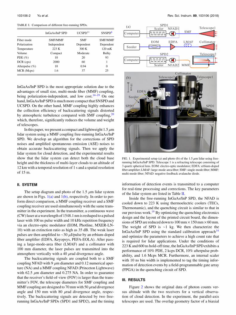
The setup diagram and photo of the 1.5 µm lidar systemare shown in Figs. 1(a) and 1(b), respectively. In order to per-form direct comparison, a MMF coupling receiver and a SMFcoupling receiver are used simultaneously with the same trans-mitter in the experiment. In the transmitter, a continuous wave(CW) laser at a wavelength of 1548.1 nm is reshaped to a pulsedlaser with 100 ns pulse width and 10 kHz repetition frequencyvia an electro-optic modulator (EOM, Photline, MXER-LN-10) with an extinction ratio as high as 35 dB. The weak laserpulses are then amplified to ∼30 µJ/pulse by an erbium-dopedfiber amplifier (EDFA, Keyopsys, PEFA-EOLA). After pass-ing a large-mode-area fiber (LMAF) and a collimator with100 mm diameter, the laser pulses are transmitted into theatmosphere vertically with a 40 µrad divergence angle.
The backscattering signals are coupled both to a SMFcoupling NFAD with 9 µm diameter and 0.12 numerical aper-ture (NA) and a MMF coupling NFAD (Princeton Lightwave)with 62.5 µm diameter and 0.275 NA. In order to guaranteethat the receiver’s field-of-view (FOV) is larger than the trans-mitter’s FOV, the telescope diameters for SMF coupling andMMF coupling are designed to 70 mm with 50 µrad divergenceangle and 150 mm with 80 µrad divergence angle, respec-tively. The backscattering signals are detected by two free-running InGaAs/InP SPDs (SPD1 and SPD2), and the timing
FIG. 1. Experimental setup (a) and photo (b) of the 1.5 µm lidar using free-running InGaAs/InP SPD. Telescope 1 is a refracting telescope consisting of3 quartz spherical lens. EOM: electro-optic modulator; EDFA: erbium-dopedfiber amplifier; LMAF: large-mode-area fiber; SMF: single-mode fiber; MMF:multi-mode fiber; NFAD: negative feedback avalanche diode.
information of detection events is transmitted to a computerfor real-time processing and corrections. The key parametersof the lidar system are listed in Table II.
Inside the free-running InGaAs/InP SPD, the NFAD iscooled down to 223 K using thermoelectric coolers (TECs,Thermonamic), and the quenching circuit is similar to that inour previous work.19 By optimizing the quenching electronicsdesign and the layout of the printed circuit board, the dimen-sions of SPD are reduced down to 100 mm× 150 mm× 60 mm.The weight of SPD is ∼1 kg. We then characterize theInGaAs/InP SPD using the standard calibration approach14
and optimize the parameters to achieve a high count rate thatis required for lidar applications. Under the conditions of223 K and 600 ns hold-off time, the InGaAs/InP SPD exhibits aperformance of 10% PDE, 2 kcps DCR, 10% afterpulse prob-ability, and 1.6 Mcps MCR. Furthermore, an internal scalerwith 10 ns bin width is implemented to tag the timing infor-mation of detection events by a field-programmable gate array(FPGA) in the quenching circuit of SPD.
III. RESULTS
Figure 2 shows the original data of photon counts ver-sus altitude with the two receivers for a vertical observa-tion of cloud detection. In the experiment, the parallel-axistelescopes are used. The overlap geometry factor of a biaxial
103106-3 Yu et al. Rev. Sci. Instrum. 89, 103106 (2018)
TABLE II. Parameters of the lidar system.
Parameter Value
TransmitterWavelength (µm) 1.5Pulse width (ns) 100Pulse energy (µJ) 30Repetition rate (kHz) 10Beam divergence (µrad) 40
Receiver1Detector SMF NFADTelescope diameter (mm) 70Fiber core diameter (µm) 9Fiber NA 0.12Beam divergence (µrad) 50
Receiver2Detector MMF NFADTelescope diameter (mm) 150Fiber core diameter (µm) 62.5Fiber NA 0.275Beam divergence (µrad) 80
SystemMeasurement range (km) 12Spatial resolution (m) 15Temporal resolution (s) 1Weight (kg) 15
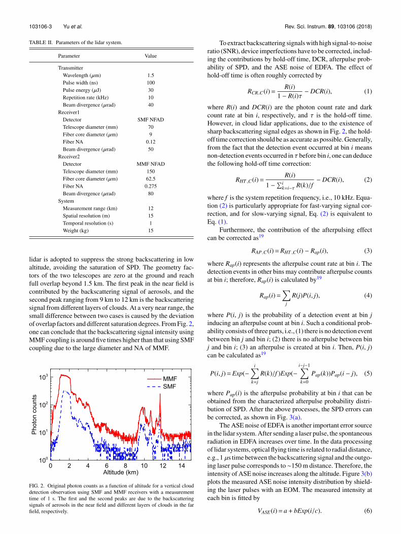
lidar is adopted to suppress the strong backscattering in lowaltitude, avoiding the saturation of SPD. The geometry fac-tors of the two telescopes are zero at the ground and reachfull overlap beyond 1.5 km. The first peak in the near field iscontributed by the backscattering signal of aerosols, and thesecond peak ranging from 9 km to 12 km is the backscatteringsignal from different layers of clouds. At a very near range, thesmall difference between two cases is caused by the deviationof overlap factors and different saturation degrees. From Fig. 2,one can conclude that the backscattering signal intensity usingMMF coupling is around five times higher than that using SMFcoupling due to the large diameter and NA of MMF.
FIG. 2. Original photon counts as a function of altitude for a vertical clouddetection observation using SMF and MMF receivers with a measurementtime of 1 s. The first and the second peaks are due to the backscatteringsignals of aerosols in the near field and different layers of clouds in the farfield, respectively.
To extract backscattering signals with high signal-to-noiseratio (SNR), device imperfections have to be corrected, includ-ing the contributions by hold-off time, DCR, afterpulse prob-ability of SPD, and the ASE noise of EDFA. The effect ofhold-off time is often roughly corrected by
RCR C(i)=R(i)
1 − R(i)τ− DCR(i), (1)
where R(i) and DCR(i) are the photon count rate and darkcount rate at bin i, respectively, and τ is the hold-off time.However, in cloud lidar applications, due to the existence ofsharp backscattering signal edges as shown in Fig. 2, the hold-off time correction should be as accurate as possible. Generally,from the fact that the detection event occurred at bin i meansnon-detection events occurred in τ before bin i, one can deducethe following hold-off time correction:
RHT C(i)=R(i)
1 −∑i
k=i−τ R(k)/f− DCR(i), (2)
where f is the system repetition frequency, i.e., 10 kHz. Equa-tion (2) is particularly appropriate for fast-varying signal cor-rection, and for slow-varying signal, Eq. (2) is equivalent toEq. (1).
Furthermore, the contribution of the afterpulsing effectcan be corrected as19
RAP C(i)=RHT C(i) − Rap(i), (3)
where Rap(i) represents the afterpulse count rate at bin i. Thedetection events in other bins may contribute afterpulse countsat bin i; therefore, Rap(i) is calculated by19
Rap(i)=∑
j
R(j)P(i, j), (4)
where P(i, j) is the probability of a detection event at bin jinducing an afterpulse count at bin i. Such a conditional prob-ability consists of three parts, i.e., (1) there is no detection eventbetween bin j and bin i; (2) there is no afterpulse between binj and bin i; (3) an afterpulse is created at bin i. Then, P(i, j)can be calculated as19
P(i, j)=Exp(−i∑
k=j
R(k)/f )Exp(−i−j−1∑k=0
Pap(k))Pap(i − j), (5)
where Pap(i) is the afterpulse probability at bin i that can beobtained from the characterized afterpulse probability distri-bution of SPD. After the above processes, the SPD errors canbe corrected, as shown in Fig. 3(a).
The ASE noise of EDFA is another important error sourcein the lidar system. After sending a laser pulse, the spontaneousradiation in EDFA increases over time. In the data processingof lidar systems, optical flying time is related to radial distance,e.g., 1 µs time between the backscattering signal and the outgo-ing laser pulse corresponds to ∼150 m distance. Therefore, theintensity of ASE noise increases along the altitude. Figure 3(b)plots the measured ASE noise intensity distribution by shield-ing the laser pulses with an EOM. The measured intensity ateach bin is fitted by
VASE(i)= a + bExp(i/c). (6)
103106-4 Yu et al. Rev. Sci. Instrum. 89, 103106 (2018)
FIG. 3. Error corrections and cloud backscattering signal extraction. (a) Orig-inal signal and the corrected signal after SPD parameter corrections. (b)Measured ASE noise intensity distribution from EDFA as a function of time(corresponding to altitude) by shielding the laser pulses. (c) ASE noise fittingin the backscattering signal. (d) Final extracted backscattering signal.
In the lidar system, the transmission telescope is colli-mated for the wavelength of laser pulses. Due to the widespectrum characteristic, the ASE noises only in the near rangecan be collected inside the receiver’s FOV. The ASE count rateis proportional to the intensity of ASE noise. In the experiment,considering that the aerosol backscattering signals are negli-gible within the range from 13 km to 15 km, we use the datain this range to fit the count rate distribution of ASE noise,RASE(i), according to Eq. (6). The fitted result is shown inFig. 3(c). Then, the final extracted signal is given by
RC(i)=RAP C(i) − RASE(i). (7)
After performing all the corrections, the SNR of backscatteringsignal is significantly enhanced, particularly at the range ofhigh altitude, as shown in Fig. 3(d).
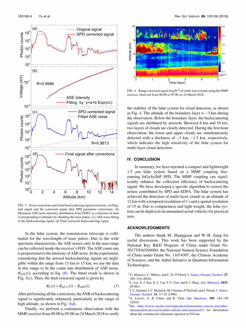
Finally, we perform a continuous observation with theMMF receiver from 00:00 to 05:00 on 24 March 2018 to verify
FIG. 4. Range corrected signal (log Pr2) of multi-layer clouds using the MMFreceiver, observed from 00:00 to 05:00 on 24 March 2018.
the stability of the lidar system for cloud detection, as shownin Fig. 4. The altitude of the boundary layer is ∼3 km duringthe observation. Below the boundary layer, the backscatteringsignals are attributed by aerosols. Between 6 km and 10 km,two layers of clouds are clearly detected. During the first hourobservation, the lower and upper clouds are simultaneouslydetected with a thickness of ∼3 km, ∼1.5 km, respectively,which indicates the high sensitivity of the lidar system formulti-layer cloud detection.
IV. CONCLUSION
In summary, we have reported a compact and lightweight1.5 µm lidar system based on a MMF coupling free-running InGaAs/InP SPD. The MMF coupling can signif-icantly enhance the collection efficiency of backscatteringsignal. We have developed a specific algorithm to correct thenoises contributed by SPD and EDFA. The lidar system hasachieved the detection of multi-layer clouds to an altitude of12 km with a temporal resolution of 1 s and a spatial resolutionof 15 m. Due to compactness and light weight, the lidar sys-tem can be deployed on unmanned aerial vehicles for practicaluses.
ACKNOWLEDGMENTS
The authors thank M. Shangguan and W.-H. Jiang foruseful discussions. This work has been supported by theNational Key R&D Program of China under Grant No.2017YFA0304004, the National Natural Science Foundationof China under Grant No. 11674307, the Chinese Academyof Sciences, and the Anhui Initiative in Quantum InformationTechnologies.
1G. Martucci, C. Milroy, and C. D. O’Dowd, J. Atmos. Oceanic Technol. 27,305–318 (2010).
2L. Liu, X. J. Sun, X. C. Liu, T. C. Gao, and S. J. Zhao, Adv. Meteorol. 2015,853861.
3J. L. Gaumet, J. C. Heinrich, M. Cluzeau, P. Pierrard, and J. Prieur, J. Atmos.Oceanic Technol. 15, 37–45 (1998).
4A. Lavrov, A. B. Utkin, and R. Vilar, Opt. Spectrosc. 109, 144–150(2010).
5See https://www.vaisala.com/en/products/instruments-sensors-and-other-measurement-devices/weather-stations-and-sensors/cl31 for informationabout the commercial ceilometer operated at 910 nm.

103106-5 Yu et al. Rev. Sci. Instrum. 89, 103106 (2018)
6F. Marsili, V. B. Verma, J. A. Stern, S. Harrington, A. E. Lita, T. Gerrits,I. Vayshenker, B. Baek, M. D. Shaw, R. P. Mirin, and S. W. Nam, Nat.Photonics 7, 210–214 (2013).
7X. Yang, H. Li, W. Zhang, L. You, L. Zhang, X. Liu, Z. Wang, W. Peng,X. Xie, and M. Jiang, Opt. Express 22, 16267–16272 (2014).
8J. Wu, L. You, S. Chen, H. Li, Y. He, C. Lv, Z. Wang, and X. Xie, Appl.Opt. 56, 2195–2200 (2017).
9M. Shangguan, H. Xia, C. Wang, J. Qiu, S. Lin, X. Dou, Q. Zhang, andJ.-W. Pan, Opt. Lett. 42, 3541–3544 (2017).
10J. Qiu, H. Xia, X. Dou, M. Li, M. Shangguan, C. Wang, X. Shang, S. Lin,and J. Liu, Opt. Lett. 42, 4454–4457 (2017).
11H. Xia, G.-L. Shentu, M. Shangguan, X.-X. Xia, X. Jia, C. Wang, J. Zhang,J. S. Pelc, M. M. Fejer, Q. Zhang, X. Dou, and J.-W. Pan, Opt. Lett. 40,1579–1582 (2015).
12M. Shangguan, H. Xia, C. Wang, J. Qiu, G.-L. Shentu, Q. Zhang, X. Dou,and J.-W. Pan, Opt. Express 24, 19322–19336 (2016).
13H. Xia, M. Shangguan, C. Wang, G.-L. Shentu, J. Qiu, Q. Zhang, X. Dou,and J.-W. Pan, Opt. Lett. 41, 5218–5221 (2016).
14J. Zhang, M. A. Itzler, H. Zbinden, and J.-W. Pan, Light Sci. Appl. 4, e286(2015).
15X. Jiang, M. A. Itzler, K. O’Donnell, M. Entwistle, and K. Slomkowski,“InGaAs/InP negative feedback avalanche diodes (NFADs),” Proc. SPIE.8033, 80330K (2011).
16Z. Yan, D. R. Hamel, A. K. Heinrichs, X. Jiang, M. A. Itzler, andT. Jennewein, Rev. Sci. Instrum. 83, 073105 (2012).
17T. Lunghi, C. Barreiro, O. Guinnard, R. Houlmann, X. Jiang, M. A. Itzler,and H. Zbinden, J. Mod. Opt. 59, 1481 (2012).
18B. Korzh, N. Walenta, T. Lunghi, N. Gisin, and H. Zbinden, Appl. Phys.Lett. 104, 081108 (2014).
19C. Yu, M. Shangguan, H. Xia, J. Zhang, X. Dou, and J.-W. Pan, Opt. Express25, 14611–14620 (2017).
20Y. Dikmelik and F. M. Davidson, Appl. Opt. 44, 4946–4952 (2005).