CERTIFICATES OF COMPETENCY IN THE MERCHANT NAVY · PDF fileCERTIFICATES OF COMPETENCY IN THE...
27
CERTIFICATES OF COMPETENCY IN THE MERCHANT NAVY – MARINE ENGINEER OFFICER EXAMINATIONS ADMINISTERED BY THE SCOTTISH QUALIFICATIONS AUTHORITY ON BEHALF OF THE MARITIME AND COASTGUARD AGENCY STCW 95 CHIEF ENGINEER REG. III/2 (UNLIMITED) 041-34 – NAVAL ARCHITECTURE FRIDAY, 14 DECEMBER 2012 0915 - 1215 hrs Examination paper inserts: Notes for the guidance of candidates: Materials to be supplied by examination centres: Candidate’s examination workbook Graph paper Worksheet Q2 1. Non-programmable calculators may be used. 2. All formulae used must be stated and the method of working and ALL intermediate steps must be made clear in the answer.
Transcript of CERTIFICATES OF COMPETENCY IN THE MERCHANT NAVY · PDF fileCERTIFICATES OF COMPETENCY IN THE...
CERTIFICATES OF COMPETENCY IN THE MERCHANT NAVY –
MARINE ENGINEER OFFICER
EXAMINATIONS ADMINISTERED BY THE
SCOTTISH QUALIFICATIONS AUTHORITY
ON BEHALF OF THE
MARITIME AND COASTGUARD AGENCY
STCW 95 CHIEF ENGINEER REG. III/2 (UNLIMITED)
041-34 – NAVAL ARCHITECTURE
FRIDAY, 14 DECEMBER 2012
0915 - 1215 hrs
Examination paper inserts:
Notes for the guidance of candidates:
Materials to be supplied by examination centres:
Candidate’s examination workbook
Graph paper
Worksheet Q2
1. Non-programmable calculators may be used.
2. All formulae used must be stated and the method of working and ALL intermediate steps must
be made clear in the answer.

[OVER
NAVAL ARCHITECTURE
Attempt SIX questions only
All questions carry equal marks
Marks for each part question are shown in brackets
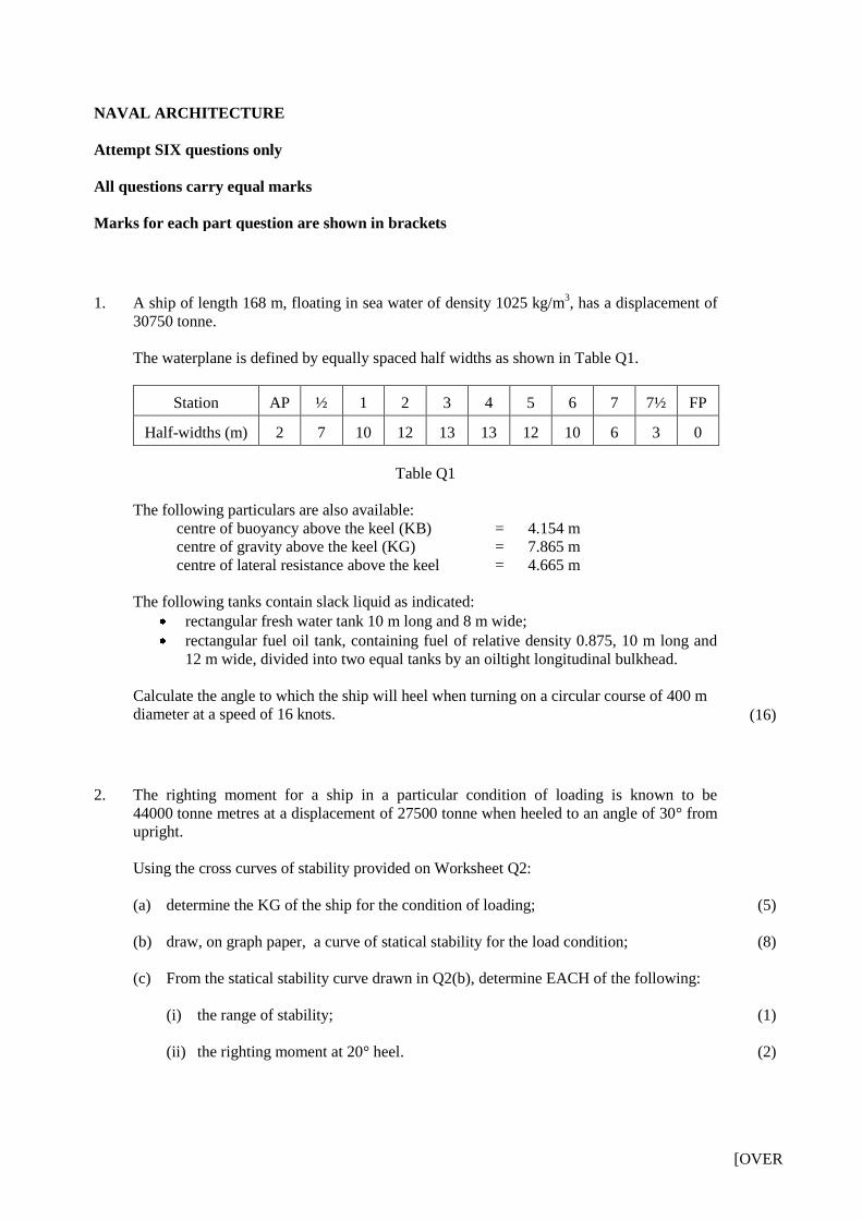
1. A ship of length 168 m, floating in sea water of density 1025 kg/m3, has a displacement of
30750 tonne.
The waterplane is defined by equally spaced half widths as shown in Table Q1.
Station AP ½ 1 2 3 4 5 6 7 7½ FP
Half-widths (m) 2 7 10 12 13 13 12 10 6 3 0
Table Q1
The following particulars are also available:
centre of buoyancy above the keel (KB) = 4.154 m
centre of gravity above the keel (KG) = 7.865 m
centre of lateral resistance above the keel = 4.665 m
The following tanks contain slack liquid as indicated:
rectangular fresh water tank 10 m long and 8 m wide;
rectangular fuel oil tank, containing fuel of relative density 0.875, 10 m long and
12 m wide, divided into two equal tanks by an oiltight longitudinal bulkhead.
Calculate the angle to which the ship will heel when turning on a circular course of 400 m
diameter at a speed of 16 knots.
(16)
2. The righting moment for a ship in a particular condition of loading is known to be
44000 tonne metres at a displacement of 27500 tonne when heeled to an angle of 30° from
upright.
Using the cross curves of stability provided on Worksheet Q2:
(a) determine the KG of the ship for the condition of loading;
(b) draw, on graph paper, a curve of statical stability for the load condition;
(c) From the statical stability curve drawn in Q2(b), determine EACH of the following:
(i) the range of stability;
(ii) the righting moment at 20° heel.
(5)
(8)
(1)
(2)
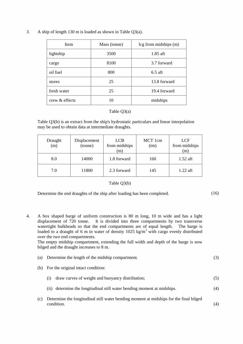
3. A ship of length 130 m is loaded as shown in Table Q3(a).
Item Mass (tonne) lcg from midships (m)
lightship 3500 1.85 aft
cargo 8100 3.7 forward
oil fuel 800 6.5 aft
stores 25 13.8 forward
fresh water 25 19.4 forward
crew & effects 10 midships
Table Q3(a)
Table Q3(b) is an extract from the ship's hydrostatic particulars and linear interpolation
may be used to obtain data at intermediate draughts.
Draught
(m)
Displacement
(tonne)
LCB
from midships
(m)
MCT 1cm
(tm)
LCF
from midships
(m)
8.0 14000 1.8 forward 160 1.52 aft
7.0 11800 2.3 forward 145 1.22 aft
Table Q3(b)
Determine the end draughts of the ship after loading has been completed.
(16)
4. A box shaped barge of uniform construction is 80 m long, 10 m wide and has a light
displacement of 720 tonne. It is divided into three compartments by two transverse
watertight bulkheads so that the end compartments are of equal length. The barge is
loaded to a draught of 6 m in water of density 1025 kg/m3 with cargo evenly distributed
over the two end compartments.
The empty midship compartment, extending the full width and depth of the barge is now
bilged and the draught increases to 8 m.
(a) Determine the length of the midship compartment.
(b) For the original intact condition:
(i) draw curves of weight and buoyancy distribution;
(ii) determine the longitudinal still water bending moment at midships.
(c) Determine the longitudinal still water bending moment at midships for the final bilged
condition.
(3)
(5)
(4)
(4)
[OVER
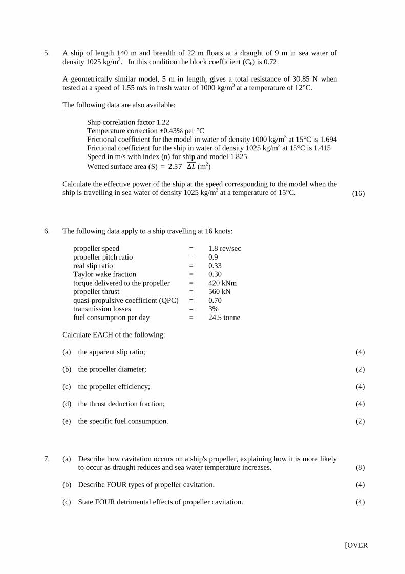
5. A ship of length 140 m and breadth of 22 m floats at a draught of 9 m in sea water of
density 1025 kg/m3. In this condition the block coefficient (Cb) is 0.72.
A geometrically similar model, 5 m in length, gives a total resistance of 30.85 N when
tested at a speed of 1.55 m/s in fresh water of 1000 kg/m3 at a temperature of 12°C.
The following data are also available:
Ship correlation factor 1.22
Temperature correction ±0.43% per °C
Frictional coefficient for the model in water of density 1000 kg/m3 at 15°C is 1.694
Frictional coefficient for the ship in water of density 1025 kg/m3 at 15°C is 1.415
Speed in m/s with index (n) for ship and model 1.825
Wetted surface area (S) = (m2)
Calculate the effective power of the ship at the speed corresponding to the model when the
ship is travelling in sea water of density 1025 kg/m3 at a temperature of 15°C.
(16)
6. The following data apply to a ship travelling at 16 knots:
propeller speed = 1.8 rev/sec
propeller pitch ratio = 0.9
real slip ratio = 0.33
Taylor wake fraction = 0.30
torque delivered to the propeller = 420 kNm
propeller thrust = 560 kN
quasi-propulsive coefficient (QPC) = 0.70
transmission losses = 3%
fuel consumption per day = 24.5 tonne
Calculate EACH of the following:
(a) the apparent slip ratio;
(b) the propeller diameter;
(c) the propeller efficiency;
(d) the thrust deduction fraction;
(e) the specific fuel consumption.
(4)
(2)
(4)
(4)
(2)
7. (a) Describe how cavitation occurs on a ship's propeller, explaining how it is more likely
to occur as draught reduces and sea water temperature increases.
(b) Describe FOUR types of propeller cavitation.
(c) State FOUR detrimental effects of propeller cavitation.
(8)
(4)
(4)
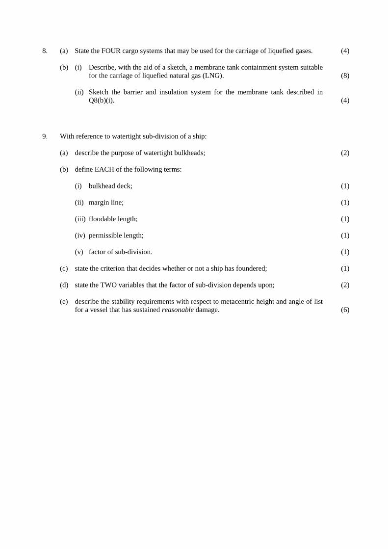
8. (a) State the FOUR cargo systems that may be used for the carriage of liquefied gases.
(b) (i) Describe, with the aid of a sketch, a membrane tank containment system suitable
for the carriage of liquefied natural gas (LNG).
(ii) Sketch the barrier and insulation system for the membrane tank described in
Q8(b)(i).
(4)
(8)
(4)
9. With reference to watertight sub-division of a ship:
(a) describe the purpose of watertight bulkheads;
(b) define EACH of the following terms:
(i) bulkhead deck;
(ii) margin line;
(iii) floodable length;
(iv) permissible length;
(v) factor of sub-division.
(c) state the criterion that decides whether or not a ship has foundered;
(d) state the TWO variables that the factor of sub-division depends upon;
(e) describe the stability requirements with respect to metacentric height and angle of list
for a vessel that has sustained reasonable damage.
(2)
(1)
(1)
(1)
(1)
(1)
(1)
(2)
(6)
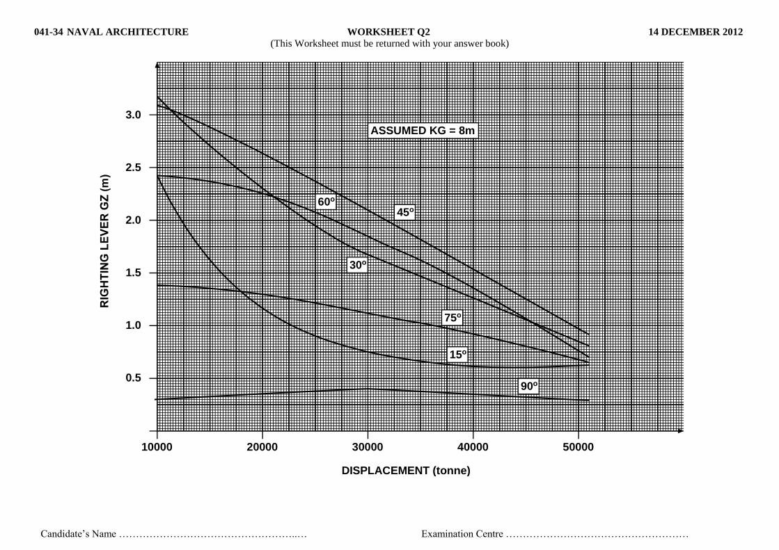
041-34 NAVAL ARCHITECTURE WORKSHEET Q2 14 DECEMBER 2012
(This Worksheet must be returned with your answer book)
Candidate’s Name ……………………………………………..… Examination Centre ………………………………………………
3.0
2.5
2.0
1.5
1.0
0.5
10000 20000 30000 40000 50000
DISPLACEMENT (tonne)
ASSUMED KG = 8m
45o
30o
60o
75o
15o
90o
CERTIFICATES OF COMPETENCY IN THE MERCHANT NAVY –
MARINE ENGINEER OFFICER
EXAMINATIONS ADMINISTERED BY THE
SCOTTISH QUALIFICATIONS AUTHORITY
ON BEHALF OF THE
MARITIME AND COASTGUARD AGENCY
STCW 95 CHIEF ENGINEER REG. III/2 (UNLIMITED)
041-34 – NAVAL ARCHITECTURE
FRIDAY, 19 OCTOBER 2012
0915 - 1215 hrs
Examination paper inserts:
Notes for the guidance of candidates:
Materials to be supplied by examination centres:
Candidate’s examination workbook
Graph paper
1. Non-programmable calculators may be used.
2. All formulae used must be stated and the method of working and ALL intermediate steps must
be made clear in the answer.

[OVER
NAVAL ARCHITECTURE
Attempt SIX questions only
All questions carry equal marks
Marks for each part question are shown in brackets
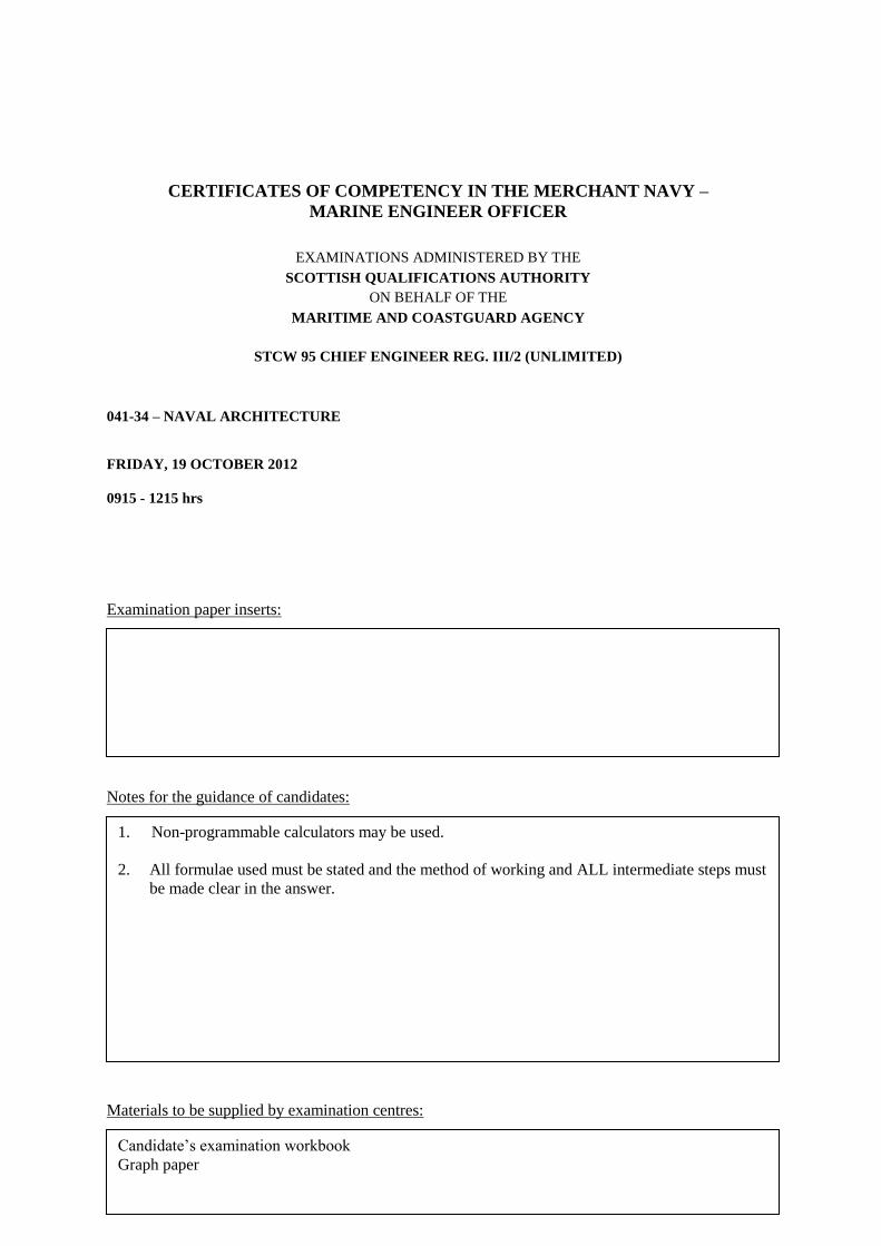
1. A RO-RO ferry of length 80 m has a displacement of 3800 tonne in sea water of density
1025 kg/m3 with BM = 3.4 m.
The breadth of the ship at the waterline, between sections 3 and 7 is constant at 13 m.
To increase stability, sponsons, 1.8 m deep and of constant plan area are to be fitted as
shown in Fig Q1.
Fig Q1
The sponsons extend over the midship length between sections 3 and 7, with sponson
widths as shown in Table Q1.
Section 3 4 5 6 7
Sponson width (m) 0 1.2 1.8 1.2 0
Table Q1
For the new condition there is no change in draught and the load waterline is at mid-depth
of the sponson.
Calculate the increase in BM due to the sponsons.
(16)
SPONSON
0 1 2 3 4 5 6 7 8 9 10
2. The ‘wall sided formula’ gives an expression for righting lever (GZ) as follows:
GZ = sin θ (GM + ½ BM tan2 θ)
(a) Derive an expression for the `angle of loll' of a ship which is initially unstable in still
water, using the wall sided formula.
(b) A box shaped vessel designed to carry timber, is 80 m long, 12 m wide and floats at a
draught of 5 m in sea water of density 1025 kg/m3 with a KG of 4.815 m. A beam
wind acts on the exposed area of the vessel causing it to heel to an angle of 15°.
The heeling moment caused by the wind is given by the expression:
Heeling moment = 0.85 A b v2 cos
2 θ Nm
where: A = exposed area = 627 m2
b = lever = 6.5 m
v = wind speed in m/s
θ = angle of heel in degrees.
Calculate the wind speed in knots, using the wall sided formula for GZ.
(5)
(11)
3. A ship of displacement 11000 tonne has a length 120 m, breadth 16 m, and even keel
draught of 5.5 m in sea water of density 1025 kg/m3. The area of the waterplane is
1440 m2 and the second moment of area of the waterplane about a transverse axis through
midships is 1.2 × 10⁶ m
4 with the LCF at midships.
The ship has a full depth empty rectangular compartment of length 12 m and breadth 10 m.
The centre of the compartment is on the centreline of the ship 40 m forward of midships.
Calculate the end draughts after the compartment is bilged.
Note: For the purposes of calculating the MCT1cm it can be assumed that GML = BML
(16)
[OVER
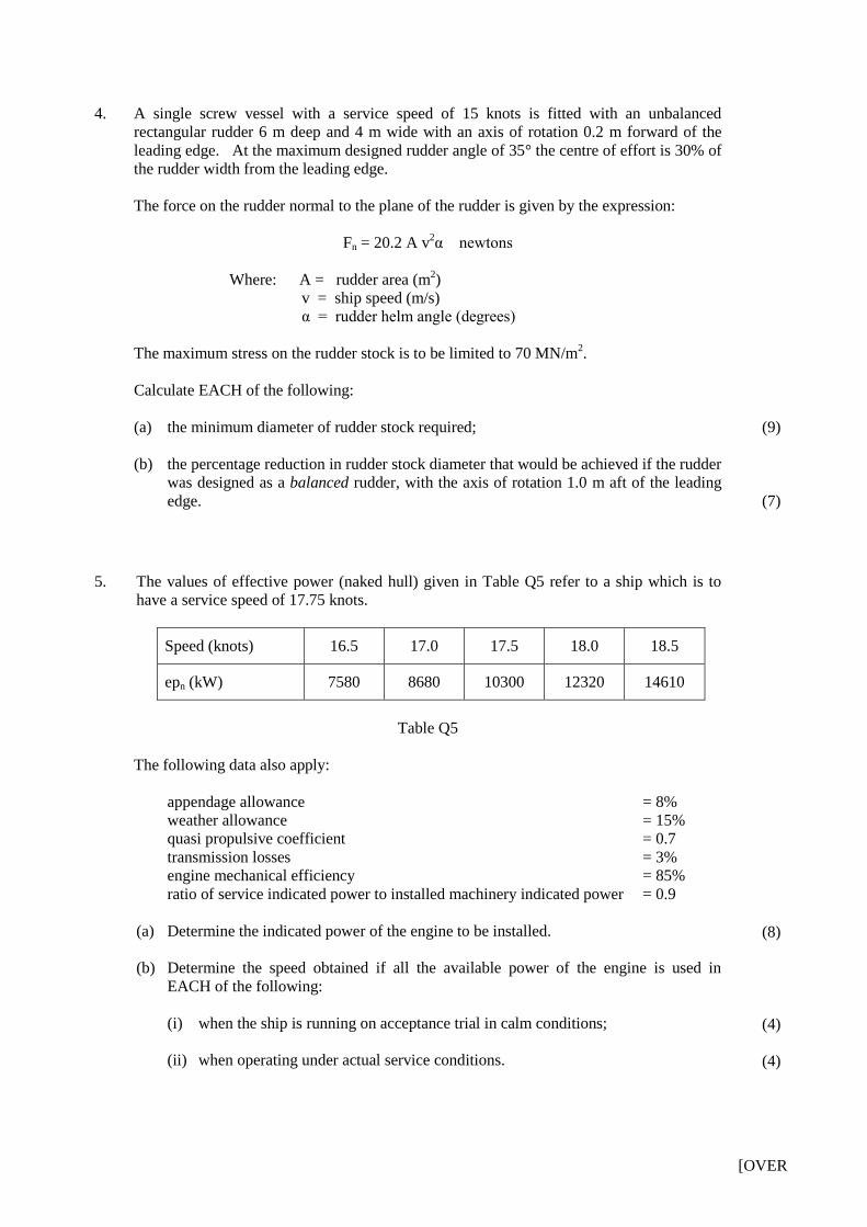
4. A single screw vessel with a service speed of 15 knots is fitted with an unbalanced
rectangular rudder 6 m deep and 4 m wide with an axis of rotation 0.2 m forward of the
leading edge. At the maximum designed rudder angle of 35° the centre of effort is 30% of
the rudder width from the leading edge.
The force on the rudder normal to the plane of the rudder is given by the expression:
Fn = 20.2 A v2α newtons
Where: A = rudder area (m2)
v = ship speed (m/s)
α = rudder helm angle (degrees)
The maximum stress on the rudder stock is to be limited to 70 MN/m2.
Calculate EACH of the following:
(a) the minimum diameter of rudder stock required;
(b) the percentage reduction in rudder stock diameter that would be achieved if the rudder
was designed as a balanced rudder, with the axis of rotation 1.0 m aft of the leading
edge.
(9)
(7)
5. The values of effective power (naked hull) given in Table Q5 refer to a ship which is to
have a service speed of 17.75 knots.
Speed (knots) 16.5 17.0 17.5 18.0 18.5
epn (kW) 7580 8680 10300 12320 14610
Table Q5
The following data also apply:
appendage allowance = 8%
weather allowance = 15%
quasi propulsive coefficient = 0.7
transmission losses = 3%
engine mechanical efficiency = 85%
ratio of service indicated power to installed machinery indicated power = 0.9
(a) Determine the indicated power of the engine to be installed.
(b) Determine the speed obtained if all the available power of the engine is used in
EACH of the following:
(i) when the ship is running on acceptance trial in calm conditions;
(ii) when operating under actual service conditions.
(8)
(4)
(4)
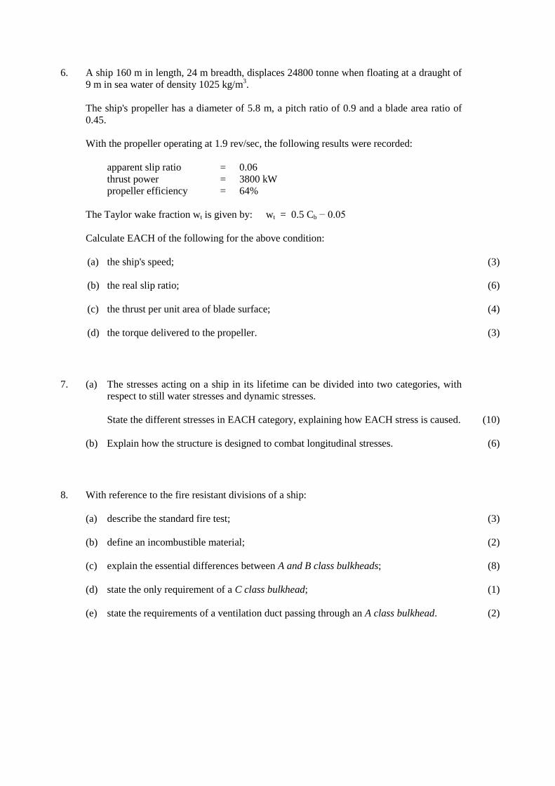
6. A ship 160 m in length, 24 m breadth, displaces 24800 tonne when floating at a draught of
9 m in sea water of density 1025 kg/m3.
The ship's propeller has a diameter of 5.8 m, a pitch ratio of 0.9 and a blade area ratio of
0.45.
With the propeller operating at 1.9 rev/sec, the following results were recorded:
apparent slip ratio = 0.06
thrust power = 3800 kW
propeller efficiency = 64%
The Taylor wake fraction wt is given by: wt = 0.5 Cb − 0.05
Calculate EACH of the following for the above condition:
(a) the ship's speed;
(b) the real slip ratio;
(c) the thrust per unit area of blade surface;
(d) the torque delivered to the propeller.
(3)
(6)
(4)
(3)
7. (a) The stresses acting on a ship in its lifetime can be divided into two categories, with
respect to still water stresses and dynamic stresses.
State the different stresses in EACH category, explaining how EACH stress is caused. (10)
(b) Explain how the structure is designed to combat longitudinal stresses.
(10)
(6)
8. With reference to the fire resistant divisions of a ship:
(a) describe the standard fire test;
(b) define an incombustible material;
(c) explain the essential differences between A and B class bulkheads;
(d) state the only requirement of a C class bulkhead;
(e) state the requirements of a ventilation duct passing through an A class bulkhead.
(3)
(2)
(8)
(1)
(2)
9. (a) Explain, with the aid of an outline sketch, EACH of the following:
(i) balanced rudder;
(ii) semi-balanced rudder;
(iii) unbalanced rudder.
(b) State the principal advantage of fitting a balanced rudder.
(c) A ship travelling at full speed has its rudder put hard over to port, where it is held
until the ship completes a full turning circle.
Describe, with the aid of a sketch, how the ship will heel from the upright condition
during the manoeuvre by illustrating the moments produced by the forces acting on
the ship and the rudder.
(2)
(2)
(2)
(1)
(9)

RTIFICATES OF COMPETENCY IN THE MERCHANT NAVY –
MARINE ENGINEER OFFICER
EXAMINATIONS ADMINISTERED BY THE
SCOTTISH QUALIFICATIONS AUTHORITY
ON BEHALF OF THE
MARITIME AND COASTGUARD AGENCY
STCW 95 CHIEF ENGINEER REG. III/2 (UNLIMITED)
041-34 – NAVAL ARCHITECTURE
FRIDAY, 30 MARCH 2012
0915 - 1215 hrs
Examination paper inserts:
Notes for the guidance of candidates:
Materials to be supplied by examination centres:
Candidate’s examination workbook
Graph paper
1. Non-programmable calculators may be used.
2. All formulae used must be stated and the method of working and ALL intermediate steps must
be made clear in the answer.

[OVER
NAVAL ARCHITECTURE
Attempt SIX questions only
All questions carry equal marks
Marks for each part question are shown in brackets
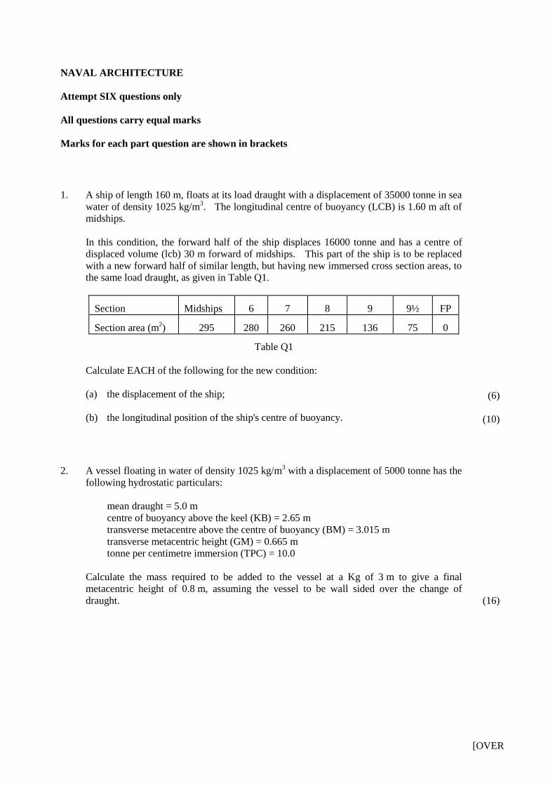
1. A ship of length 160 m, floats at its load draught with a displacement of 35000 tonne in sea
water of density 1025 kg/m3. The longitudinal centre of buoyancy (LCB) is 1.60 m aft of
midships.
In this condition, the forward half of the ship displaces 16000 tonne and has a centre of
displaced volume (lcb) 30 m forward of midships. This part of the ship is to be replaced
with a new forward half of similar length, but having new immersed cross section areas, to
the same load draught, as given in Table Q1.
Section Midships 6 7 8 9 9½ FP
Section area (m2) 295 280 260 215 136 75 0
Table Q1
Calculate EACH of the following for the new condition:
(a) the displacement of the ship;
(b) the longitudinal position of the ship's centre of buoyancy.
(6)
(10)
2. A vessel floating in water of density 1025 kg/m3 with a displacement of 5000 tonne has the
following hydrostatic particulars:
mean draught = 5.0 m
centre of buoyancy above the keel (KB) = 2.65 m
transverse metacentre above the centre of buoyancy (BM) = 3.015 m
transverse metacentric height (GM) = 0.665 m
tonne per centimetre immersion (TPC) = 10.0
Calculate the mass required to be added to the vessel at a Kg of 3 m to give a final
metacentric height of 0.8 m, assuming the vessel to be wall sided over the change of
draught.
(16)
3. A ship of length 150 m has the following hydrostatic particulars when floating at an even
keel draught in sea water.
waterplane area = 2000 m2
displacement = 13500 tonne
longitudinal metacentric height (GML) = 165 m
centre of flotation from midships (LCF) = 2.4 m aft
The ship grounds on a rock which may be assumed to be at a point 60 m forward of
midships and settles such that the end draughts are 6.35 m aft and 5.65 m forward.
Calculate the original draught of the ship.
(16)
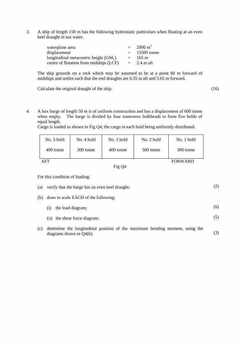
4. A box barge of length 50 m is of uniform construction and has a displacement of 600 tonne
when empty. The barge is divided by four transverse bulkheads to form five holds of
equal length.
Cargo is loaded as shown in Fig Q4, the cargo in each hold being uniformly distributed.
No. 5 hold
400 tonne
No. 4 hold
300 tonne
No. 3 hold
400 tonne
No. 2 hold
500 tonne
No. 1 hold
300 tonne
AFT FORWARD
Fig Q4
For this condition of loading:
(a) verify that the barge has an even keel draught;
(b) draw to scale EACH of the following:
(i) the load diagram;
(ii) the shear force diagram;
(c) determine the longitudinal position of the maximum bending moment, using the
diagrams drawn in Q4(b).
(2)
(6)
(5)
(3)
[OVER
5. A ship of length 160 m and breadth 28 m floats at a draught of 12 m in sea water of density
1025 kg/m3 with a block coefficient of 0.7.
allowance for appendages = 6%
allowance for weather = 14%
quasi-propulsive coefficient (QPC) = 0.71
A geometrically similar model 8 m in length, when tested at a speed of 1.6 m/s in fresh
water of density 1000 kg/m3 gives a total resistance of 82 N.
Calculate the service delivered power for the ship at the corresponding speed to that of the
model.
Note: The frictional coefficient for the model in fresh water is 1.69
The frictional coefficient for the ship in sea water is 1.42
Speed is in m/s with index (n) = 1.825
Wetted surface area (m) =
(16)
6. (a) Explain the term thrust deduction, with respect to a ship’s propeller.
(b) The following data were obtained during a ships acceptance trials:
ship speed = 15.6 knots
delivered power = 2600 kW
effective power = 1750 kW
thrust = 280 kN
propeller efficiency = 65%
apparent slip = 6%
Calculate EACH of the following:
(i) the thrust deduction fraction;
(ii) the Taylor wake fraction;
(iii) the true slip;
(iv) the hull efficiency.
(3)
(3)
(5)
(3)
(2)
7. (a) Sketch outline midship sections for chemical carriers of Types 1, 2 and 3 showing the
location of the cargo.
(b) With reference to the outlines sketched in Q7(a), explain how the location of the
cargo fulfils the requirements of the IMO Bulk Chemical Codes.
(c) Explain how the design of a chemical tanker minimises the problems of incompatible
cargoes.
(d) Explain why corrugated bulkheads are fitted where possible, in preference to plane
bulkheads in chemical carriers.
(3)
(5)
(5)
(3)
8. (a) Explain the circumstances under which whipping stresses may occur in ships.
(b) Describe the use of stress indicators on board a ship.
(c) Sketch a graph of stress versus time indicating whipping.
(d) Describe the structure on a ship that would resist whipping.
(4)
(4)
(2)
(6)
9. (a) State the reasons for carrying out sea trials on a newly built ship.
(b) (i) Outline the purpose of progressive speed trials.
(ii) Describe how such trials are conducted.
(iii) State FOUR other tests which may be conducted during sea trials.
(5)
(2)
(5)
(4)
CERTIFICATES OF COMPETENCY IN THE MERCHANT NAVY –
MARINE ENGINEER OFFICER
EXAMINATIONS ADMINISTERED BY THE
SCOTTISH QUALIFICATIONS AUTHORITY
ON BEHALF OF THE
MARITIME AND COASTGUARD AGENCY
STCW 95 CHIEF ENGINEER REG. III/2 (UNLIMITED)
041-34 – NAVAL ARCHITECTURE
FRIDAY, 20 JULY 2012
0915 - 1215 hrs
Examination paper inserts:
Notes for the guidance of candidates:
Materials to be supplied by examination centres:
Candidate’s examination workbook
Graph paper
Worksheet Q3
1. Non-programmable calculators may be used.
2. All formulae used must be stated and the method of working and ALL intermediate steps must
be made clear in the answer.

[OVER
NAVAL ARCHITECTURE
Attempt SIX questions only
All questions carry equal marks
Marks for each part question are shown in brackets
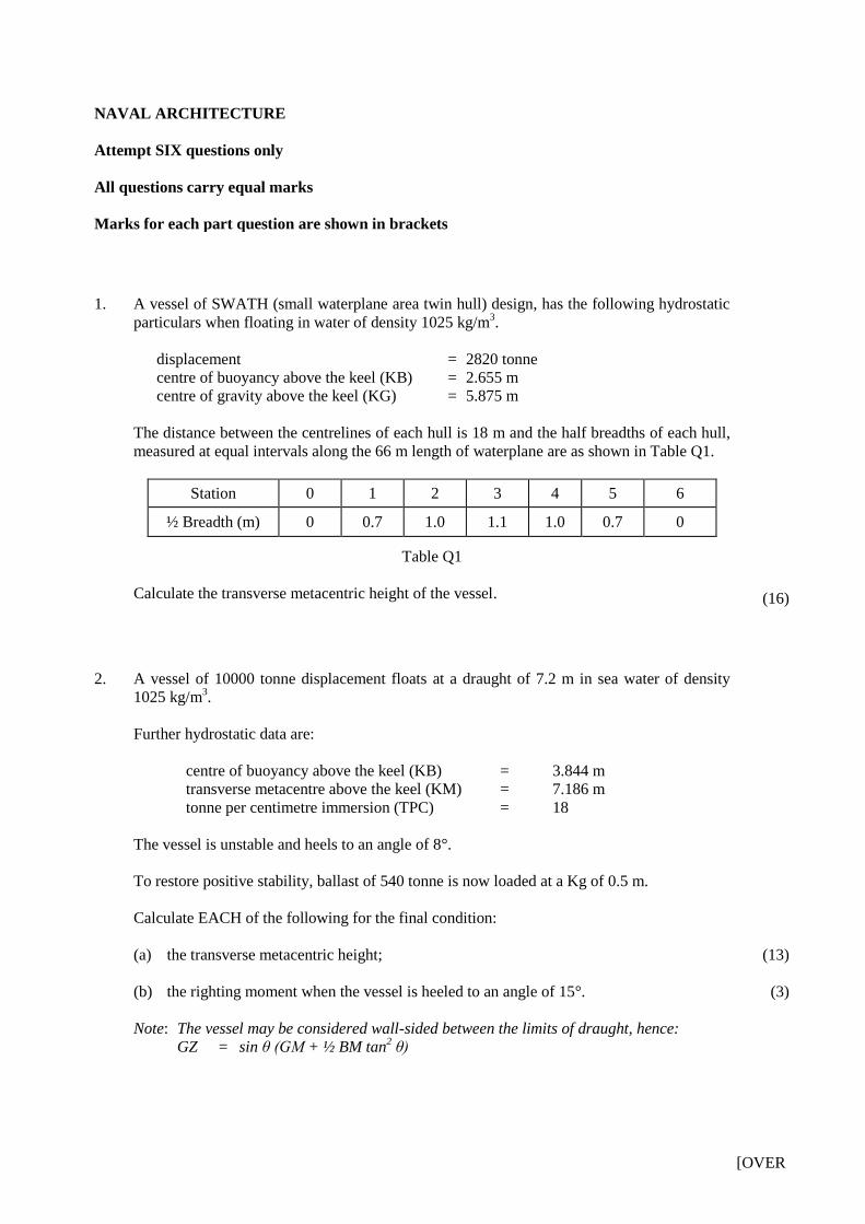
1. A vessel of SWATH (small waterplane area twin hull) design, has the following hydrostatic
particulars when floating in water of density 1025 kg/m3.
displacement = 2820 tonne
centre of buoyancy above the keel (KB) = 2.655 m
centre of gravity above the keel (KG) = 5.875 m
The distance between the centrelines of each hull is 18 m and the half breadths of each hull,
measured at equal intervals along the 66 m length of waterplane are as shown in Table Q1.
Station 0 1 2 3 4 5 6
½ Breadth (m) 0 0.7 1.0 1.1 1.0 0.7 0
Table Q1
Calculate the transverse metacentric height of the vessel.
(16)
2. A vessel of 10000 tonne displacement floats at a draught of 7.2 m in sea water of density
1025 kg/m3.
Further hydrostatic data are:
centre of buoyancy above the keel (KB) = 3.844 m
transverse metacentre above the keel (KM) = 7.186 m
tonne per centimetre immersion (TPC) = 18
The vessel is unstable and heels to an angle of 8°.
To restore positive stability, ballast of 540 tonne is now loaded at a Kg of 0.5 m.
Calculate EACH of the following for the final condition:
(a) the transverse metacentric height;
(b) the righting moment when the vessel is heeled to an angle of 15°.
Note: The vessel may be considered wall-sided between the limits of draught, hence:
GZ = sin θ (GM + ½ BM tan2 θ)
(13)
(3)
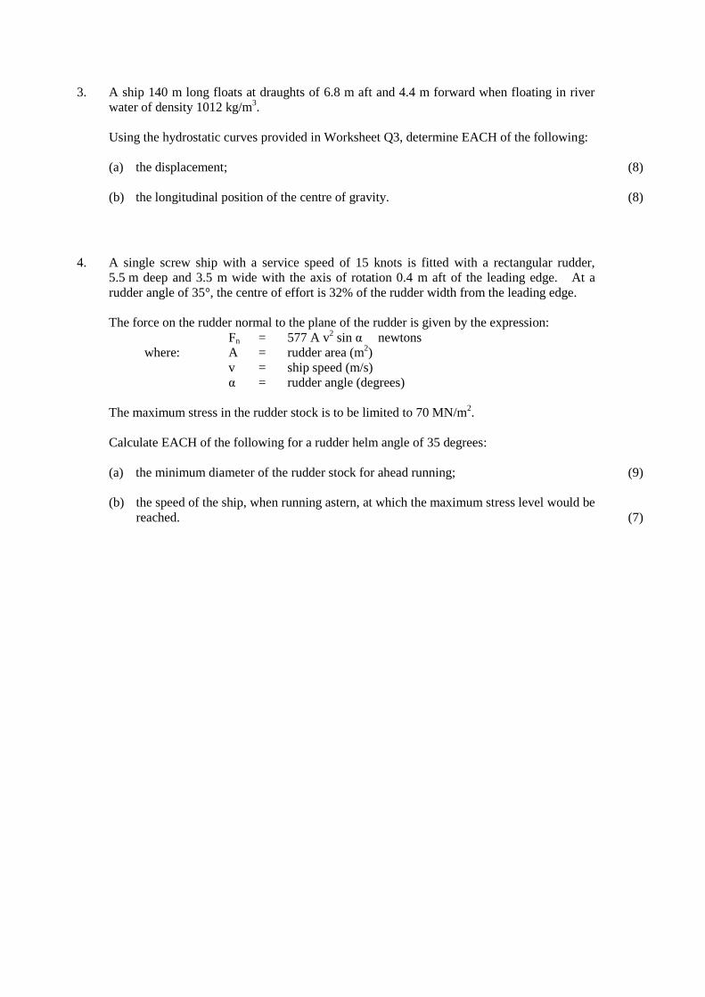
3. A ship 140 m long floats at draughts of 6.8 m aft and 4.4 m forward when floating in river
water of density 1012 kg/m3.
Using the hydrostatic curves provided in Worksheet Q3, determine EACH of the following:
(a) the displacement;
(b) the longitudinal position of the centre of gravity.
(8)
(8)
4. A single screw ship with a service speed of 15 knots is fitted with a rectangular rudder,
5.5 m deep and 3.5 m wide with the axis of rotation 0.4 m aft of the leading edge. At a
rudder angle of 35°, the centre of effort is 32% of the rudder width from the leading edge.
The force on the rudder normal to the plane of the rudder is given by the expression:
Fn = 577 A v2 sin α newtons
where: A = rudder area (m2)
v = ship speed (m/s)
α = rudder angle (degrees)
The maximum stress in the rudder stock is to be limited to 70 MN/m2.
Calculate EACH of the following for a rudder helm angle of 35 degrees:
(a) the minimum diameter of the rudder stock for ahead running;
(b) the speed of the ship, when running astern, at which the maximum stress level would be
reached.
(9)
(7)
[OVER
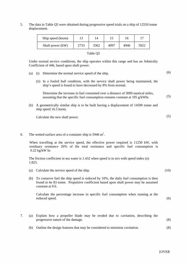
5. The data in Table Q5 were obtained during progressive speed trials on a ship of 12550 tonne
displacement.
Ship speed (knots) 13 14 15 16 17
Shaft power (kW) 2733 3362 4097 4946 5922
Table Q5
Under normal service conditions, the ship operates within this range and has an Admiralty
Coefficient of 446, based upon shaft power.
(a) (i) Determine the normal service speed of the ship.
(ii) In a fouled hull condition, with the service shaft power being maintained, the
ship’s speed is found to have decreased by 8% from normal.
Determine the increase in fuel consumed over a distance of 3000 nautical miles,
assuming that the specific fuel consumption remains constant at 195 g/kWhr.
(b) A geometrically similar ship is to be built having a displacement of 14500 tonne and
ship speed 16.5 knots.
Calculate the new shaft power.
(6)
(5)
(5)
6. The wetted surface area of a container ship is 5946 m2.
When travelling at the service speed, the effective power required is 11250 kW, with
residuary resistance 26% of the total resistance and specific fuel consumption is
0.22 kg/kW hr.
The friction coefficient in sea water is 1.432 when speed is in m/s with speed index (n)
1.825.
(a) Calculate the service speed of the ship.
(b) To conserve fuel the ship speed is reduced by 10%, the daily fuel consumption is then
found to be 83 tonne. Propulsive coefficient based upon shaft power may be assumed
constant at 0.6.
Calculate the percentage increase in specific fuel consumption when running at the
reduced speed.
(10)
(6)
7. (a) Explain how a propeller blade may be eroded due to cavitation, describing the
progressive nature of the damage.
(b) Outline the design features that may be considered to minimise cavitation.
(8)
(8)
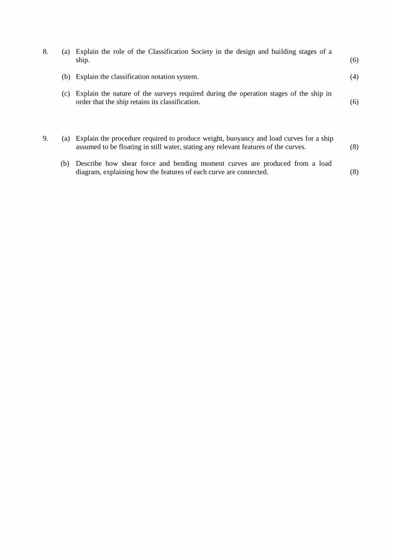
8. (a) Explain the role of the Classification Society in the design and building stages of a
ship.
(b) Explain the classification notation system.
(c) Explain the nature of the surveys required during the operation stages of the ship in
order that the ship retains its classification.
(6)
(4)
(6)
9. (a) Explain the procedure required to produce weight, buoyancy and load curves for a ship
assumed to be floating in still water, stating any relevant features of the curves.
(b) Describe how shear force and bending moment curves are produced from a load
diagram, explaining how the features of each curve are connected.
(8)
(8)
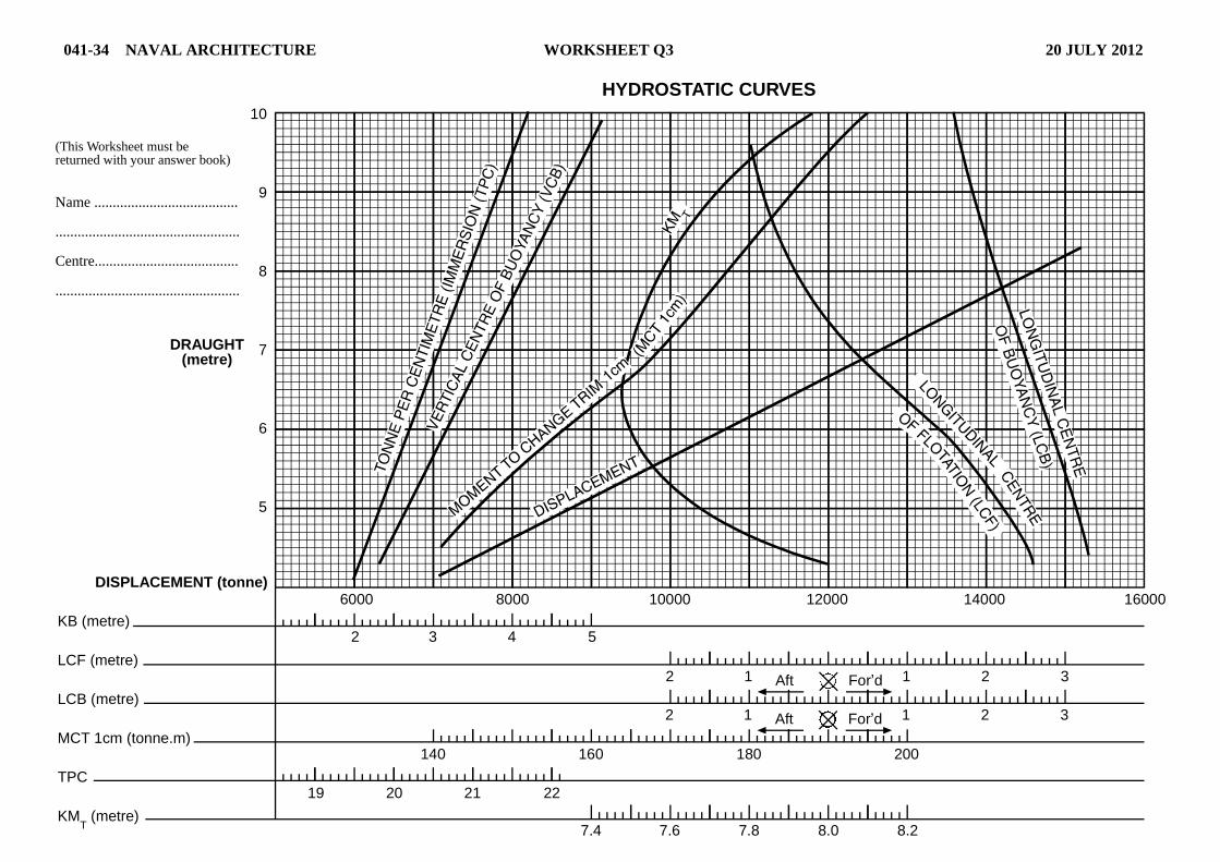
041-34 NAVAL ARCHITECTURE WORKSHEET Q3 20 JULY 2012
DISPLACEMENT (tonne)
KB (metre)
LCF (metre)
LCB (metre)
MCT 1cm (tonne.m)
TPC
KMT (metre)
10
9
8
7
6
5
(This Worksheet must bereturned with your answer book)
Name .......................................
..................................................
Centre.......................................
..................................................
DRAUGHT(metre)
6000 8000 10000 12000 14000 16000
2 3 4 5
2 1 1 2Aft For’d
2 1 1 2Aft For’d
3
3
200180160140
21 22
7.4 7.6 7.8 8.0 8.2
2019
HYDROSTATIC CURVES