PTFE / PFA LINED PIPES AND FITTINGS DIN 2848 - … · Test according to standard ... < 107 Ω based...
19
ARMYLOR ® PTFE / PFA LINED PIPES AND FITTINGS DIN 2848
Transcript of PTFE / PFA LINED PIPES AND FITTINGS DIN 2848 - … · Test according to standard ... < 107 Ω based...
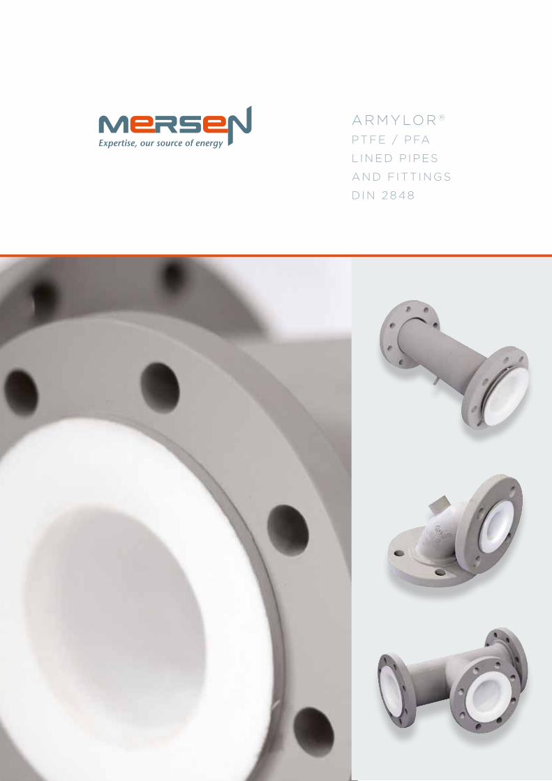
ARMYLOR ®
PTFE / PFA
L INED P IPES
AND F ITT INGS
DIN 2848
CONTENT
EXPERTISE p.1
MERSEN ANTICORROSION EQUIPMENT p.2
PTFE / PFA POLYMERS p.3
PTFE / PFA LINING p.4
STEEL PARTS p.7
LINED COMPONENTS p.9
QUALITY CONTROL p.10
INSTALLATION PROCEDURES p.11
CODING SYSTEM AND REFERENCES p.13
MANUFACTURING PROCESS p.14
PRODUCTS p.15
MERSEN ANTICORROSION EQUIPMENT
21
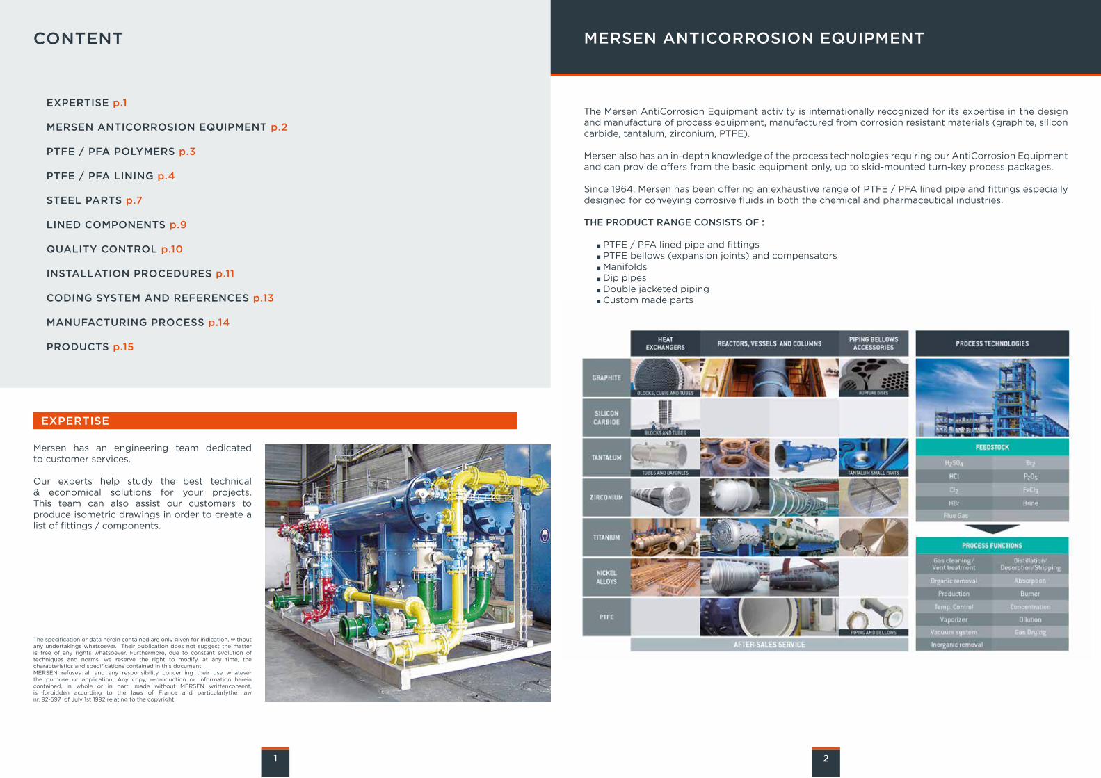
The Mersen AntiCorrosion Equipment activity is internationally recognized for its expertise in the design and manufacture of process equipment, manufactured from corrosion resistant materials (graphite, silicon carbide, tantalum, zirconium, PTFE).
Mersen also has an in-depth knowledge of the process technologies requiring our AntiCorrosion Equipment and can provide offers from the basic equipment only, up to skid-mounted turn-key process packages.
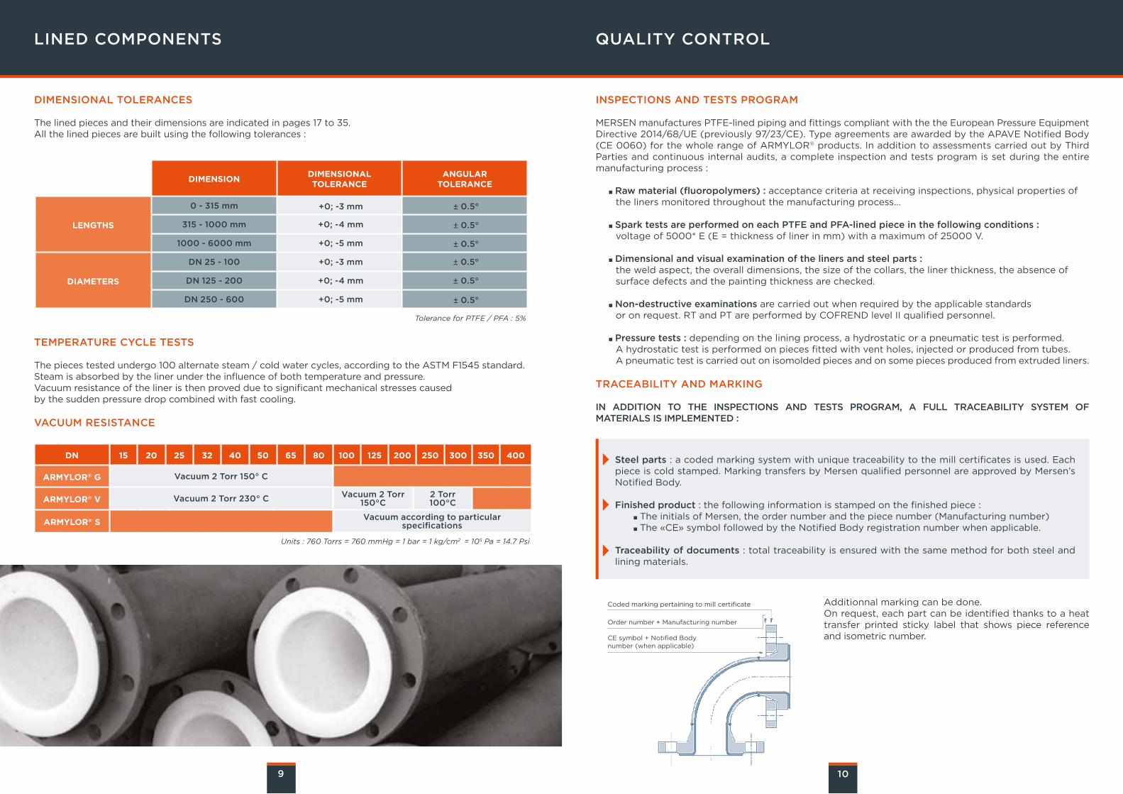
Since 1964, Mersen has been offering an exhaustive range of PTFE / PFA lined pipe and fittings especially designed for conveying corrosive fluids in both the chemical and pharmaceutical industries.
THE PRODUCT RANGE CONSISTS OF :
PTFE / PFA lined pipe and fittings PTFE bellows (expansion joints) and compensators Manifolds Dip pipes Double jacketed piping Custom made parts
Mersen has an engineering team dedicatedto customer services.
Our experts help study the best technical& economical solutions for your projects.This team can also assist our customers to produce isometric drawings in order to create a list of fittings / components.
EXPERTISE
The specification or data herein contained are only given for indication, without any undertakings whatsoever. Their publication does not suggest the matteris free of any rights whatsoever. Furthermore, due to constant evolution of techniques and norms, we reserve the right to modify, at any time, the characteristics and specifications contained in this document. MERSEN refuses all and any responsibility concerning their use whatever the purpose or application. Any copy, reproduction or information hereincontained, in whole or in part, made without MERSEN writtenconsent,is forbidden according to the laws of France and particularlythe lawnr. 92-597 of July 1st 1992 relating to the copyright.
PTFE / PFA LININGPTFE / PFA POLYMERS
DEFINITION
Available lining materials for our product range are as follows :
GENERAL CHARACTERISTICS
Values indicated in the following table are given for virgin PTFE and PFA.These characteristics can vary depending on the material grades from the various suppliers, the transformation process and the batch.
RECEIVING INSPECTIONS
Material certificates from the PTFE / PFA powder manufacturers are checked and identified with batch numbers. On request, FDA certificates (Food and Drug Administration) can be supplied.
Virgin or anti-static* PTFE (Polytetrafluoroethylene), in accordance with ASTM D4894 & 4895 standards.
Virgin or anti-static* PFA (perfluoroalkoxy), according to ASTM D3307** standard.
* Conductive black PTFE or PFA ** Also on request according to DIN 53455 standard
*amorphous phase, **crystal phase
PROPERTIES UNITS PTFE PFA
Physical
Density g/cm3 2.13 - 2.19 2.12 - 2.17
Water absorption : 24h thickness 3,2 mm % <0.01 0.03
Mechanical
Tensile strength MPa 20 - 40 27 - 32
Elongation at break % 250 - 500 300 - 500
Modulus of elasticity under elongation MPa 350 - 750 650 - 700
Modulus of elasticity under flexural stress MPa 440 - 670 590 - 700
Hardness shore D mandhod 50 - 72 60 - 65
Thermal
Flame propagation hard hard
Melting point °C 327 and 342 300 to 310
Other transitions °C -90*,+123,* +27** -80*, 90*
Maximum service temperature °C -200/+260 -150/+260
Temp. of deflection under load (1.82 MPa) °C 50 - 60 50
Linear elongation coefficient 105 / °C 10 - 25 12
Thermal conductivity W / m.K 0.24 0.25
Electrical
Dielectric constant from 60 Hz to 107 Hz 2.2 2.1
Volume resistivity Ω.cm 1018 1018
Surface resistivity Ω 1017 1017
Spark test (thick.mm) kV / mm.K 36(1) 80(2.3)
3 4
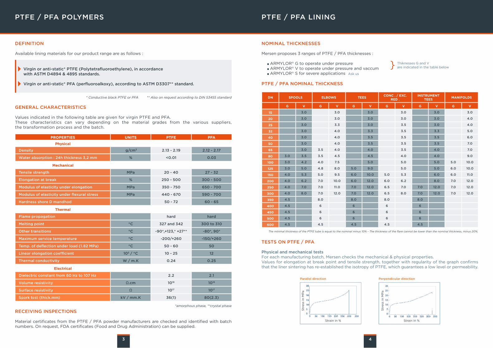
NOMINAL THICKNESSES
Mersen proposes 3 ranges of PTFE / PFA thicknesses :
ARMYLOR® G to operate under pressure ARMYLOR® V to operate under pressure and vaccum ARMYLOR® S for severe applications
PTFE / PFA NOMINAL THICKNESS
} Thiknesses G and V are indicated in the table below
Ask us
The minimal thickness of the PTFE tube is equal to the nominal minus 10% - The thickness of the flare cannot be lower than the nominal thickness, minus 20%.
DN SPOOLS ELBOWS TEESCONC . / EXC.
RED .INSTRUMENT
TEESMANIFOLDS
G V G V G V G V G V G V
15 3.0 3.0 3.0 3.0 3.0 3.0
20 3.0 3.0 3.0 3.0 3.0 4.0
25 3.0 3.3 3.0 3.5 3.0 4.0
32 3.0 4.0 3.3 3.5 3.3 5.0
40 3.0 4.0 3.5 3.5 3.5 6.0
50 3.0 4.0 3.5 3.5 3.5 7.0
65 3.0 3.5 4.0 4.0 3.5 4.0 7.0
80 3.0 3.5 3.5 4.5 4.5 4.0 4.0 9.0
100 3.0 4.2 4.0 7.5 5.0 5.0 5.0 5.0 10.0
125 3.0 5.0 4.8 8.0 5.0 9.0 5.0 5.0 6.0 10.0
150 4.0 5.3 5.0 9.5 6.0 10.0 5.0 5.3 6.0 6.0 11.0
200 4.0 6.2 7.0 10.0 6.0 12.0 6.0 6.2 8.0 7.0 12.0
250 4.0 7.0 7.0 11.0 7.0 12.0 6.5 7.0 7.0 12.0 7.0 12.0
300 4.0 8.0 7.0 12.0 7.0 12.0 6.5 8.0 7.0 12.0 7.0 12.0
350 4.5 8.0 8.0 8.0 8.0
400 4.5 6 6 6 6
450 4.5 6 6 6 6
500 4.5 6 6 6 6
600 4.5 4.5 4.5 4.5 4.5
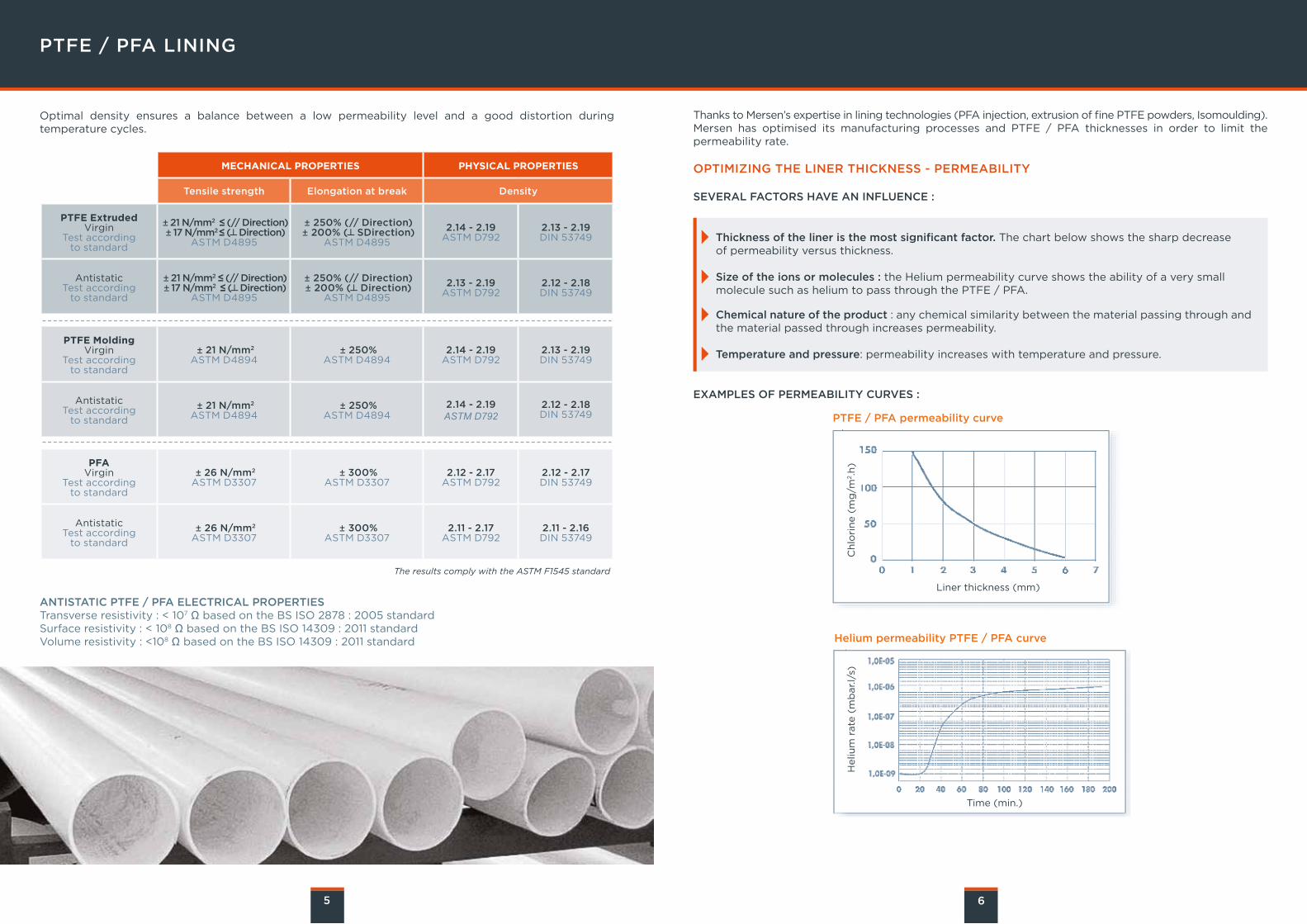
TESTS ON PTFE / PFA
Physical and mechanical testsFor each manufacturing batch, Mersen checks the mechanical & physical properties.Values for elongation at break point and tensile strength, together with regularity of the graph confirms that the liner sintering has re-established the isotropy of PTFE, which guarantees a low level or permeability.
Parallel direction Perpendicular direction
Strain in % Strain in %
Str
ess
in
MP
a
Str
ess
in
MP
a
PTFE / PFA LINING
Optimal density ensures a balance between a low permeability level and a good distortion during temperature cycles.
The results comply with the ASTM F1545 standard
5 6
Thanks to Mersen’s expertise in lining technologies (PFA injection, extrusion of fine PTFE powders, Isomoulding). Mersen has optimised its manufacturing processes and PTFE / PFA thicknesses in order to limit the permeability rate.
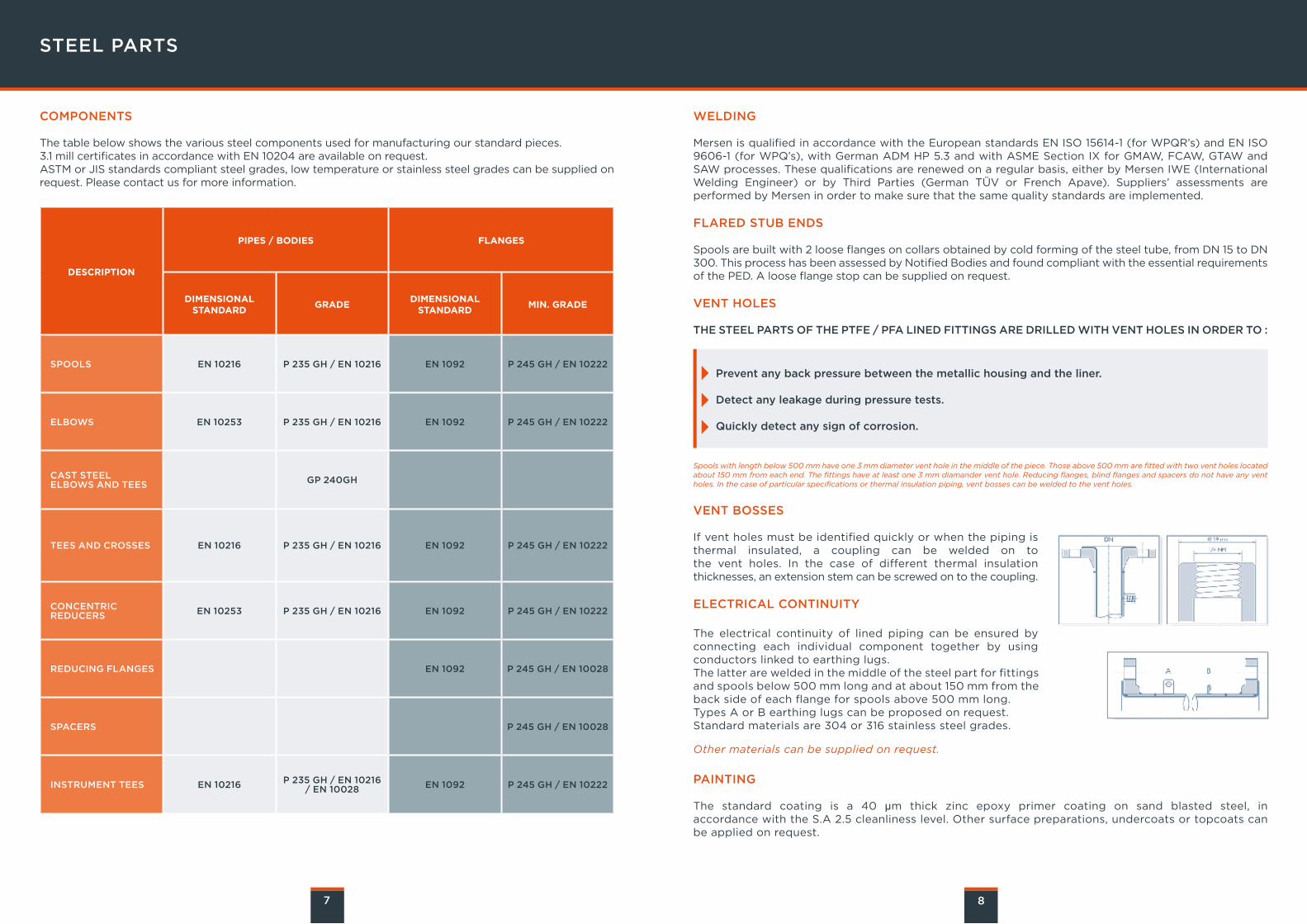
OPTIMIZING THE LINER THICKNESS - PERMEABILITY
SEVERAL FACTORS HAVE AN INFLUENCE :
EXAMPLES OF PERMEABILITY CURVES :
MECHANICAL PROPERTIES PHYSICAL PROPERTIES
Tensile strength Elongation at break Density
PTFE ExtrudedVirgin
Test according to standard
± 21 N/mm2²≤ (// Direction) ± 17 N/mm2 ≤ (┴ Direction)
ASTM D4895
± 250% (// Direction) ± 200% (┴ SDirection)
ASTM D4895
2.14 - 2.19ASTM D792
2.13 - 2.19DIN 53749
AntistaticTest according
to standard
± 21 N/mm2 ≤ (// Direction) ± 17 N/mm2²≤ (┴ Direction)
ASTM D4895
± 250% (// Direction) ± 200% (┴ Direction)
ASTM D4895
2.13 - 2.19ASTM D792
2.12 - 2.18DIN 53749
PTFE MoldingVirgin
Test according to standard
± 21 N/mm2
ASTM D4894 ± 250%
ASTM D4894 2.14 - 2.19
ASTM D7922.13 - 2.19DIN 53749
AntistaticTest according
to standard
± 21 N/mm2
ASTM D4894 ± 250%
ASTM D48942.14 - 2.19ASTM D792
2.12 - 2.18DIN 53749
PFAVirgin
Test according to standard
± 26 N/mm2
ASTM D3307 ± 300%
ASTM D33072.12 - 2.17
ASTM D7922.12 - 2.17DIN 53749
AntistaticTest according
to standard
± 26 N/mm2
ASTM D3307 ± 300%
ASTM D33072.11 - 2.17
ASTM D7922.11 - 2.16DIN 53749
ANTISTATIC PTFE / PFA ELECTRICAL PROPERTIESTransverse resistivity : < 107 Ω based on the BS ISO 2878 : 2005 standardSurface resistivity : < 108 Ω based on the BS ISO 14309 : 2011 standardVolume resistivity : <108 Ω based on the BS ISO 14309 : 2011 standard
PTFE / PFA permeability curve
Helium permeability PTFE / PFA curve
Ch
lori
ne (
mg
/m2.h
)H
eliu
m r
ate
(m
bar.l/
s)
Liner thickness (mm)
Time (min.)
Thickness of the liner is the most significant factor. The chart below shows the sharp decrease of permeability versus thickness.
Size of the ions or molecules : the Helium permeability curve shows the ability of a very small molecule such as helium to pass through the PTFE / PFA.
Chemical nature of the product : any chemical similarity between the material passing through and the material passed through increases permeability.
Temperature and pressure: permeability increases with temperature and pressure.
STEEL PARTS
COMPONENTS
The table below shows the various steel components used for manufacturing our standard pieces.3.1 mill certificates in accordance with EN 10204 are available on request.ASTM or JIS standards compliant steel grades, low temperature or stainless steel grades can be supplied on request. Please contact us for more information.
DESCRIPTION
PIPES / BODIES FLANGES
DIMENSIONAL STANDARD
GRADEDIMENSIONAL
STANDARDMIN. GRADE
SPOOLS EN 10216 P 235 GH / EN 10216 EN 1092 P 245 GH / EN 10222
ELBOWS EN 10253 P 235 GH / EN 10216 EN 1092 P 245 GH / EN 10222
CAST STEEL ELBOWS AND TEES GP 240GH
TEES AND CROSSES EN 10216 P 235 GH / EN 10216 EN 1092 P 245 GH / EN 10222
CONCENTRICREDUCERS EN 10253 P 235 GH / EN 10216 EN 1092 P 245 GH / EN 10222
REDUCING FLANGES EN 1092 P 245 GH / EN 10028
SPACERS P 245 GH / EN 10028
INSTRUMENT TEES EN 10216 P 235 GH / EN 10216/ EN 10028 EN 1092 P 245 GH / EN 10222
7 8
WELDING
Mersen is qualified in accordance with the European standards EN ISO 15614-1 (for WPQR’s) and EN ISO 9606-1 (for WPQ’s), with German ADM HP 5.3 and with ASME Section IX for GMAW, FCAW, GTAW and SAW processes. These qualifications are renewed on a regular basis, either by Mersen IWE (InternationalWelding Engineer) or by Third Parties (German TÜV or French Apave). Suppliers’ assessments are performed by Mersen in order to make sure that the same quality standards are implemented.
FLARED STUB ENDS
Spools are built with 2 loose flanges on collars obtained by cold forming of the steel tube, from DN 15 to DN 300. This process has been assessed by Notified Bodies and found compliant with the essential requirements of the PED. A loose flange stop can be supplied on request.
VENT HOLES
THE STEEL PARTS OF THE PTFE / PFA LINED FITTINGS ARE DRILLED WITH VENT HOLES IN ORDER TO :
Prevent any back pressure between the metallic housing and the liner.
Detect any leakage during pressure tests.
Quickly detect any sign of corrosion.
Spools with length below 500 mm have one 3 mm diameter vent hole in the middle of the piece. Those above 500 mm are fitted with two vent holes located about 150 mm from each end. The fittings have at least one 3 mm diamander vent hole. Reducing flanges, blind flanges and spacers do not have any vent holes. In the case of particular specifications or thermal insulation piping, vent bosses can be welded to the vent holes.
VENT BOSSES
If vent holes must be identified quickly or when the piping is thermal insulated, a coupling can be welded on to the vent holes. In the case of different thermal insulation thicknesses, an extension stem can be screwed on to the coupling.
ELECTRICAL CONTINUITY
The electrical continuity of lined piping can be ensured by connecting each individual component together by using conductors linked to earthing lugs.The latter are welded in the middle of the steel part for fittings and spools below 500 mm long and at about 150 mm from the back side of each flange for spools above 500 mm long.Types A or B earthing lugs can be proposed on request. Standard materials are 304 or 316 stainless steel grades.
Other materials can be supplied on request.
PAINTING
The standard coating is a 40 μm thick zinc epoxy primer coating on sand blasted steel, in accordance with the S.A 2.5 cleanliness level. Other surface preparations, undercoats or topcoats can be applied on request.
LINED COMPONENTS QUALITY CONTROL
DIMENSIONAL TOLERANCES
The lined pieces and their dimensions are indicated in pages 17 to 35.All the lined pieces are built using the following tolerances :
TEMPERATURE CYCLE TESTS
The pieces tested undergo 100 alternate steam / cold water cycles, according to the ASTM F1545 standard.Steam is absorbed by the liner under the influence of both temperature and pressure.Vacuum resistance of the liner is then proved due to significant mechanical stresses caused by the sudden pressure drop combined with fast cooling.
VACUUM RESISTANCE
9 10
INSPECTIONS AND TESTS PROGRAM
MERSEN manufactures PTFE-lined piping and fittings compliant with the the European Pressure Equipment Directive 2014/68/UE (previously 97/23/CE). Type agreements are awarded by the APAVE Notified Body (CE 0060) for the whole range of ARMYLOR® products. In addition to assessments carried out by Third Parties and continuous internal audits, a complete inspection and tests program is set during the entire manufacturing process :
Raw material (fluoropolymers) : acceptance criteria at receiving inspections, physical properties of the liners monitored throughout the manufacturing process...
Spark tests are performed on each PTFE and PFA-lined piece in the following conditions : voltage of 5000* E (E = thickness of liner in mm) with a maximum of 25000 V.
Dimensional and visual examination of the liners and steel parts : the weld aspect, the overall dimensions, the size of the collars, the liner thickness, the absence of surface defects and the painting thickness are checked.
Non-destructive examinations are carried out when required by the applicable standards or on request. RT and PT are performed by COFREND level II qualified personnel.
Pressure tests : depending on the lining process, a hydrostatic or a pneumatic test is performed. A hydrostatic test is performed on pieces fitted with vent holes, injected or produced from tubes. A pneumatic test is carried out on isomolded pieces and on some pieces produced from extruded liners.
TRACEABILITY AND MARKING
IN ADDITION TO THE INSPECTIONS AND TESTS PROGRAM, A FULL TRACEABILITY SYSTEM OF MATERIALS IS IMPLEMENTED :
Tolerance for PTFE / PFA : 5%
Units : 760 Torrs = 760 mmHg = 1 bar = 1 kg/cm2²= 105 Pa = 14.7 Psi
DIMENSIONDIMENSIONALTOLERANCE
ANGULARTOLERANCE
LENGTHS
0 - 315 mm +0; -3 mm ± 0.5°
315 - 1000 mm +0; -4 mm ± 0.5°
1000 - 6000 mm +0; -5 mm ± 0.5°
DIAMETERS
DN 25 - 100 +0; -3 mm ± 0.5°
DN 125 - 200 +0; -4 mm ± 0.5°
DN 250 - 600 +0; -5 mm ± 0.5°
DN 15 20 25 32 40 50 65 80 100 125 200 250 300 350 400
ARMYLOR® G Vacuum 2 Torr 150° C
ARMYLOR® V Vacuum 2 Torr 230° C Vacuum 2 Torr 150°C
2 Torr 100°C
ARMYLOR® SVacuum according to particular
specifications
Steel parts : a coded marking system with unique traceability to the mill certificates is used. Each piece is cold stamped. Marking transfers by Mersen qualified personnel are approved by Mersen’s Notified Body.
Finished product : the following information is stamped on the finished piece : The initials of Mersen, the order number and the piece number (Manufacturing number) The «CE» symbol followed by the Notified Body registration number when applicable.
Traceability of documents : total traceability is ensured with the same method for both steel and lining materials.
Additionnal marking can be done.On request, each part can be identified thanks to a heat transfer printed sticky label that shows piece reference and isometric number.
Coded marking pertaining to mill certificate
Order number + Manufacturing number
CE symbol + Notified Bodynumber (when applicable)
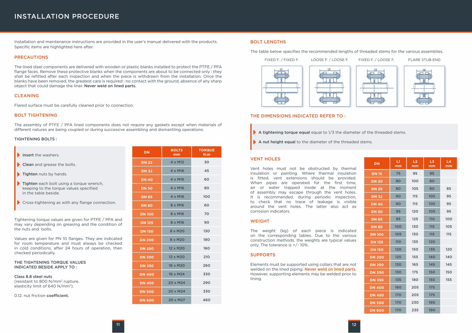
BOLT LENGTHS
The table below specifies the recommended lengths of threaded stems for the various assemblies.
THE DIMENSIONS INDICATED REFER TO :
FIXED F. / FIXED F. LOOSE F. / LOOSE F. FIXED F. / LOOSE F. FLARE STUB END
INSTALLATION PROCEDURE
Installation and maintenance instructions are provided in the user’s manual delivered with the products.Specific items are highlighted here after.
PRECAUTIONS The lined steel components are delivered with wooden or plastic blanks installed to protect the PTFE / PFA flange faces. Remove these protective blanks when the components are about to be connected only : they shall be refitted after each inspection and when the piece is withdrawn from the installation. Once the blanks have been removed, the greatest care is required : no contact with the ground, absence of any sharp object that could damage the liner. Never weld on lined parts.
CLEANING Flared surface must be carefully cleaned prior to connection.
BOLT TIGHTENING The assembly of PTFE / PFA lined components does not require any gaskets except when materials of different natures are being coupled or during successive assembling and dismantling operations.
TIGHTENING BOLTS :
11 12
Insert the washers.
Clean and grease the bolts.
Tighten nuts by hands.
Tighten each bolt using a torque wrench, keeping to the torque values specified in the table beside.
Cross-tightening as with any flange connection.
Tightening torque values are given for PTFE / PFA and may vary depending on greasing and the condition of the nuts and bolts.
Values are given for PN 10 flanges. They are indicated for room temperature and must always be checked in cold conditions, after 24 hours of operation, then checked periodically.
THE TIGHTENING TORQUE VALUESINDICATED BESIDE APPLY TO :
Class 8.8 steel nuts(resistant to 800 N/mm2 rupture, elasticity limit of 640 N/mm2).
0.12. nut friction coefficient.
DNBOLTS
mmTORQUE
N.m
DN 25 4 x M12 30
DN 32 4 x M16 45
DN 40 4 x M16 60
DN 50 4 x M16 80
DN 65 4 x M16 100
DN 80 8 x M16 60
DN 100 8 x M16 70
DN 125 8 x M16 90
DN 150 8 x M20 130
DN 200 8 x M20 180
DN 250 12 x M20 160
DN 300 12 x M20 210
DN 350 16 x M20 260
DN 400 16 x M24 330
DN 450 20 x M24 290
DN 500 20 x M24 330
DN 600 20 x M27 460
DNL1
mmL2
mmL3
mmL4mm
DN 15 75 95 85
DN 20 80 100 90
DN 25 80 105 90 85
DN 32 90 115 105 95
DN 40 90 115 105 95
DN 50 95 120 105 95
DN 65 95 125 110 100
DN 80 100 130 115 105
DN 100 105 130 115 115
DN 125 110 135 120
DN 150 120 150 135 120
DN 200 125 155 140 140
DN 250 130 165 145 145
DN 300 130 175 150 150
DN 350 135 180 155 155
DN 400 160 205 175
DN 450 170 205 175
DN 500 170 230 190
DN 600 170 235 190
VENT HOLES
Vent holes must not be obstructed by thermalinsulation or painting. Where thermal insulation is fitted, vent extensions should be provided. When pipes are operated for the first time, air or water trapped inside at the momentof assembly may escape through the vent holes.It is recommended, during periodic inspection, to check that no trace of leakage is visible around the vent holes. The latter also act ascorrosion indicators.
WEIGHT
The weight (kg) of each piece is indicatedon the corresponding tables. Due to the variousconstruction methods, the weights are typical valuesonly. The tolerance is +/- 10%.
SUPPORTS
Elements must be supported using collars that are not welded on the lined piping. Never weld on lined parts. However, supporting elements may be welded prior to lining.
A tightening torque equal equal to 1/3 the diameter of the threaded stems.
A nut height equal to the diameter of the threaded stems.
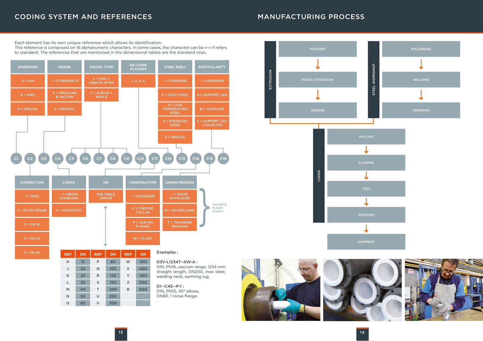
CODING SYSTEM AND REFERENCES MANUFACTURING PROCESS
Each element has its own unique reference which allows its identification. This reference is composed on 16 alphanumeric characters. In some cases, the character can be «-» if refers to standard. The references that are mentioned in the dimensional tables are the standard ones.
13 14
CONNECTION
1 = PN10
2 = PN 20/150LBS
3 = PN 16
4 = PN 50
5 = PN 40
- = VIRGIN STANDARD
A = ANTISTATIC
LINING
SEE TABLE UNDER
DN
- = STANDARD
C = TUB END COLLAR
P = SLIP ON FLANGE
W = FLARE
CONSTRUCTION
- = PASTE EXTRUSION
M = ISO-MOLDING
T = TRANSFERMOLDING
LINING PROCESS
}Accordingto eachproduct
DIMENSION
D = DIN
A = ANSI
S = SPECIAL
- = STANDARD G
V = PRESSURE & VACCUM
S = SPECIAL
RANGE
L = PIPE + LENGTH IN MM
C = ELBOW + ANGLE
PIECES TYPE
1, 2, 3, 4
NB LOOSEFLANGES
- = STANDARD
K = CAST STEEL
X = STAINLESS STEEL
S = SPECIAL
STEEL SHELL
- = STANDARD
A = SUPPORT LEG
B = COUPLING
C = SUPPORT LEG + COUPLING
PARTICULARITY
C1 C2 C3 C4 C5 C6 C7 C8 C9 C10 C11 C12 C13 C14 C15 C16
REP DN REP DN REP DN
H 15 P 80 W 350
J 20 Q 100 X 400
K 25 R 125 Y 450
L 32 S 150 Z 500
M 40 T 200 B 600
N 50 U 250
O 65 V 300
Examples :
D3V-L1234T--XW-A : DIN, PN16, vaccum range, 1234 mm straight length, DN200, inox steel, welding neck, earthing lug.
D1--C45--P-1 : DIN, PN10, 45° elbow, DN80, 1 loose flange..
EX
TR
US
ION
ST
EE
L W
OR
KS
HO
P
POWDER MACHINING
PASTE EXTRUSION WELDING
BAKING GRINDING
LIN
ING
PULLING
FLARING
TEST
PAINTING
SHIPMENT
R = LOWTEMPERATURE
STEEL
PRODUCTS DATA SHEETS
DIN FLANGES PN 10 AND PIPES p.16
FLANGED SPOOLS p.17
ELBOWS p.18
EQUAL TEES p.19
REDUCING TEES p.20-21
CONCENTRIC & ECCENTRIC REDUCERS p.22
REDUCING FLANGES p.23-25
INSTRUMENT TEES p.26
CROSSES p.27
SPACERS p.29
SPECTACLE BLINDS p.30
BLIND FLANGES & LATERAL TEES p.31
MANIFOLDS p.32
DOUBLE JACKETED PIPING p.33
DIP PIPES & ENTRY PIPES p.34
15
DIN FLANGES PN 10 AND PIPES
16
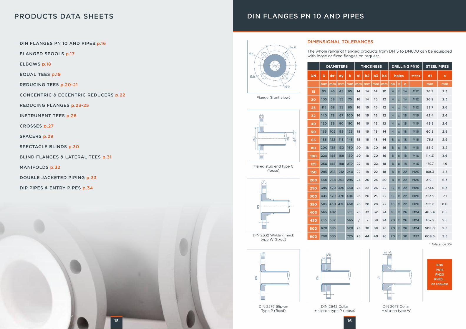
DIMENSIONAL TOLERANCES
The whole range of flanged products from DN15 to DN600 can be equipped with loose or fixed flanges on request.
DIAMETERS THICKNESS DRILLING PN10 STEEL PIPES
DN D dx* dy k b1 b2 b3 b4 holes bolting d1 s
mm mm mm mm mm mm mm mm nb x ø mm mm
15 95 45 45 65 14 14 14 10 4 x 14 M12 26.9 2.3
20 105 58 55 75 16 14 16 12 4 x 14 M12 26.9 2.3
25 115 68 55 85 16 16 16 12 4 x 14 M12 33.7 2.6
32 140 78 67 100 16 16 16 12 4 x 18 M16 42.4 2.6
40 150 88 80 110 16 16 16 12 4 x 18 M16 48.3 2.6
50 165 102 95 125 18 16 18 14 4 x 18 M16 60.3 2.9
65 185 122 118 145 18 16 18 14 8 x 18 M16 76.1 2.9
80 200 138 130 160 20 18 20 16 8 x 18 M16 88.9 3.2
100 220 158 158 180 20 18 20 16 8 x 18 M16 114.3 3.6
125 250 188 188 210 22 18 22 18 8 x 18 M16 139.7 4.0
150 285 212 212 240 22 18 22 18 8 x 22 M20 168.3 4.5
200 340 268 268 295 24 20 24 20 8 x 22 M20 219.1 6.3
250 395 320 320 350 26 22 26 22 12 x 22 M20 273.0 6.3
300 445 370 370 400 26 26 26 22 12 x 22 M20 323.9 7.1
350 505 430 430 460 26 28 28 22 16 x 22 M20 355.6 8.0
400 565 482 515 26 32 32 24 16 x 26 M24 406.4 8.5
450 615 532 565 / / 38 24 20 x 26 M24 457.2 9.5
500 670 585 620 28 38 38 26 20 x 26 M24 508.0 9.5
600 780 685 725 28 44 40 26 20 x 30 M27 609.6 9.5
Flange (front view)
* Tolerance 5%
Flared stub end type C (loose)
DIN 2632 Welding neck type W (fixed)
DIN 2576 Slip-onType P (fixed)
DIN 2642 Collar + slip-on type P (loose)
DIN 2673 Collar + slip-on type W
PN6
PN16
PN20
PN25...
on request
17
ELBOWSFLANGED SPOOLS
18
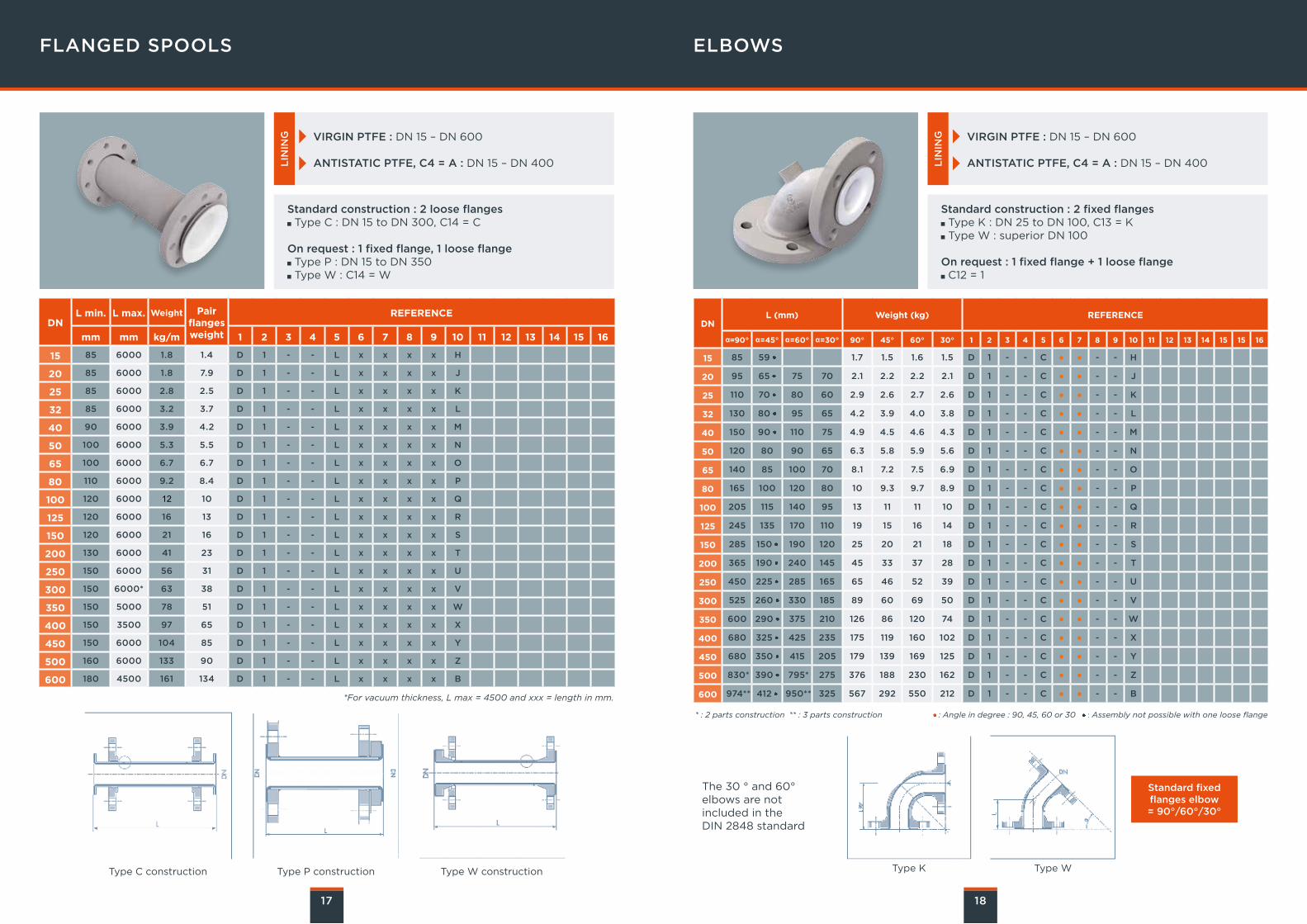
VIRGIN PTFE : DN 15 – DN 600
ANTISTATIC PTFE, C4 = A : DN 15 – DN 400LIN
ING VIRGIN PTFE : DN 15 – DN 600
ANTISTATIC PTFE, C4 = A : DN 15 – DN 400LIN
ING
Standard construction : 2 loose flanges Type C : DN 15 to DN 300, C14 = C
On request : 1 fixed flange, 1 loose flange Type P : DN 15 to DN 350 Type W : C14 = W
Standard construction : 2 fixed flanges Type K : DN 25 to DN 100, C13 = K Type W : superior DN 100
On request : 1 fixed flange + 1 loose flange C12 = 1
DNL min. L max. Weight Pair
flangesweight
REFERENCE
mm mm kg/m 1 2 3 4 5 6 7 8 9 10 11 12 13 14 15 16
15 85 6000 1.8 1.4 D 1 - - L x x x x H
20 85 6000 1.8 7.9 D 1 - - L x x x x J
25 85 6000 2.8 2.5 D 1 - - L x x x x K
32 85 6000 3.2 3.7 D 1 - - L x x x x L
40 90 6000 3.9 4.2 D 1 - - L x x x x M
50 100 6000 5.3 5.5 D 1 - - L x x x x N
65 100 6000 6.7 6.7 D 1 - - L x x x x O
80 110 6000 9.2 8.4 D 1 - - L x x x x P
100 120 6000 12 10 D 1 - - L x x x x Q
125 120 6000 16 13 D 1 - - L x x x x R
150 120 6000 21 16 D 1 - - L x x x x S
200 130 6000 41 23 D 1 - - L x x x x T
250 150 6000 56 31 D 1 - - L x x x x U
300 150 6000* 63 38 D 1 - - L x x x x V
350 150 5000 78 51 D 1 - - L x x x x W
400 150 3500 97 65 D 1 - - L x x x x X
450 150 6000 104 85 D 1 - - L x x x x Y
500 160 6000 133 90 D 1 - - L x x x x Z
600 180 4500 161 134 D 1 - - L x x x x B
*For vacuum thickness, L max = 4500 and xxx = length in mm.
Type C construction Type P construction Type W construction
DNL (mm) Weight (kg) REFERENCE
α=90° α=45° α=60° α=30° 90° 45° 60° 30° 1 2 3 4 5 6 7 8 9 10 11 12 13 14 15 15 16
15 85 59 1.7 1.5 1.6 1.5 D 1 - - C ● ● - - H
20 95 65 75 70 2.1 2.2 2.2 2.1 D 1 - - C ● ● - - J
25 110 70 80 60 2.9 2.6 2.7 2.6 D 1 - - C ● ● - - K
32 130 80 95 65 4.2 3.9 4.0 3.8 D 1 - - C ● ● - - L
40 150 90 110 75 4.9 4.5 4.6 4.3 D 1 - - C ● ● - - M
50 120 80 90 65 6.3 5.8 5.9 5.6 D 1 - - C ● ● - - N
65 140 85 100 70 8.1 7.2 7.5 6.9 D 1 - - C ● ● - - O
80 165 100 120 80 10 9.3 9.7 8.9 D 1 - - C ● ● - - P
100 205 115 140 95 13 11 11 10 D 1 - - C ● ● - - Q
125 245 135 170 110 19 15 16 14 D 1 - - C ● ● - - R
150 285 150 190 120 25 20 21 18 D 1 - - C ● ● - - S
200 365 190 240 145 45 33 37 28 D 1 - - C ● ● - - T
250 450 225 285 165 65 46 52 39 D 1 - - C ● ● - - U
300 525 260 330 185 89 60 69 50 D 1 - - C ● ● - - V
350 600 290 375 210 126 86 120 74 D 1 - - C ● ● - - W
400 680 325 425 235 175 119 160 102 D 1 - - C ● ● - - X
450 680 350 415 205 179 139 169 125 D 1 - - C ● ● - - Y
500 830* 390 795* 275 376 188 230 162 D 1 - - C ● ● - - Z
600 974** 412 950** 325 567 292 550 212 D 1 - - C ● ● - - B
* : 2 parts construction ** : 3 parts construction : Angle in degree : 90, 45, 60 or 30 : Assembly not possible with one loose flange
Standard fixed flanges elbow= 90°/60°/30°
The 30 ° and 60° elbows are notincluded in the DIN 2848 standard
Type K Type W
19
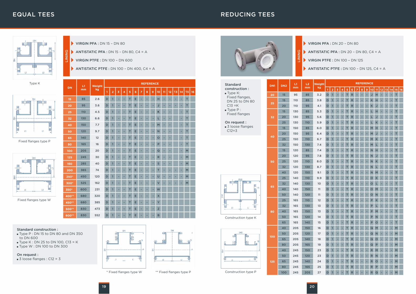
EQUAL TEES
VIRGIN PFA : DN 15 – DN 80
ANTISTATIC PFA : DN 15 – DN 80, C4 = A
VIRGIN PTFE : DN 100 – DN 600
ANTISTATIC PTFE : DN 100 – DN 400, C4 = AL
ININ
G
VIRGIN PFA : DN 20 – DN 80
ANTISTATIC PFA : DN 20 – DN 80, C4 = A
VIRGIN PTFE : DN 100 – DN 125
ANTISTATIC PTFE : DN 100 – DN 125, C4 = A
LIN
ING
Type K
Fixed flanges type P
Fixed flanges type W
REDUCING TEES
20
Construction type K
Construction type P
DNL1
mmWeight
kg
REFERENCE
1 2 3 4 5 6 7 8 9 10 11 12 13 14 15 16
15 85 2.6 D 1 - - T E - - - H - - - - T
20 95 3.6 D 1 - - T E - - - J - - - - T
25 110 4.5 D 1 - - T E - - - K - - - T
32 130 6.6 D 1 - - T E - - - L - - - T
40 150 7.7 D 1 - - T E - - - M - - - T
50 120 9.7 D 1 - - T E - - - N - - - T
65 140 12 D 1 - - T E - - - O - - - T
80 165 16 D 1 - - T E - - - P - - - T
100 205 20 D 1 - - T E - - - Q - - - M
125 245 30 D 1 - - T E - - - R - - - M
150 285 40 D 1 - - T E - - - S - - - M
200 365 74 D 1 - - T E - - - T - - - - M
250* 450 120 D 1 - - T E - - - U - - - - M
300* 525 162 D 1 - - T E - - - V - - - - M
350** 600 231 D 1 - - T E - - - W
400** 680 320 D 1 - - T E - - - X
450** 680 385 D 1 - - T E - - - Y
500** 830 473 D 1 - - T E - - - Z
600** 830 552 D 1 - - T E - - - B
Standard construction : Type P : DN 15 to DN 80 and DN 350 to DN 600
Type K : DN 25 to DN 100, C13 = K Type W : DN 100 to DN 300
On request : 3 loose flanges : C12 = 3
* Fixed flanges type W ** Fixed flanges type P
DN1 DN2L1
mmL2
mmWeight
kg
REFERENCE
1 2 3 4 5 6 7 8 9 10 11 12 13 14 15 16
20 15 95 85 3.2 D 1 - - T R - - - J H - - - T
2515 110 85 3.8 D 1 - - T R - - - K H - - - T
20 110 95 4.1 D 1 - - T R - - - K J - - - T
32
15 130 85 5.3 D 1 - - T R - - - L H - - - T
20 130 95 5.6 D 1 - - T R - - - L J - - - T
25 130 110 5.9 D 1 - - T R - - - L K - - - T
40
15 150 85 6.0 D 1 - - T R - - - M H - - - T
20 150 95 6.4 D 1 - - T R - - - M J - - - T
25 150 110 6.7 D 1 - - T R - - - M K - - - T
32 150 130 7.4 D 1 - - T R - - - M L - - - T
50
15 120 85 7.4 D 1 - - T R - - - N H - - - T
20 120 95 7.8 D 1 - - T R - - - N J - - - T
25 120 110 8.0 D 1 - - T R - - - N K - - - T
32 120 130 8.7 D 1 - - T R - - - N L - - - T
40 120 150 9.1 D 1 - - T R - - - N M - - - T
65
25 140 110 9.9 D 1 - - T R - - - O K - - - T
32 140 130 10 D 1 - - T R - - - O L - - - T
40 140 150 11 D 1 - - T R - - - O M - - - T
50 140 120 11 D 1 - - T R - - - O N - - - T
80
25 165 110 12 D 1 - - T R - - - P K - - - T
32 165 130 13 D 1 - - T R - - - P L - - - T
40 165 150 13 D 1 - - T R - - - P M - - - T
50 165 120 14 D 1 - - T R - - - P N - - - T
65 165 140 15 D 1 - - T R - - - P O - - - T
100
40 205 150 16 D 1 - - T R - - - Q M - - - M
50 205 120 17 D 1 - - T R - - - Q N - - - M
65 205 140 18 D 1 - - T R - - - Q O - - - M
80 205 165 19 D 1 - - T R - - - Q P - - - M
125
40 245 150 23 D 1 - - T R - - - R M - - - M
50 245 120 23 D 1 - - T R - - - R N - - - M
65 245 140 24 D 1 - - T R - - - R O - - - M
80 245 165 25 D 1 - - T R - - - R P - - - M
100 245 205 27 D 1 - - T R - - - R Q - - - M
Standard construction : Type K: Fixed flanges,DN 25 to DN 80C13 =K Type P : Fixed flanges
On request : 3 loose flangesC12=3
21
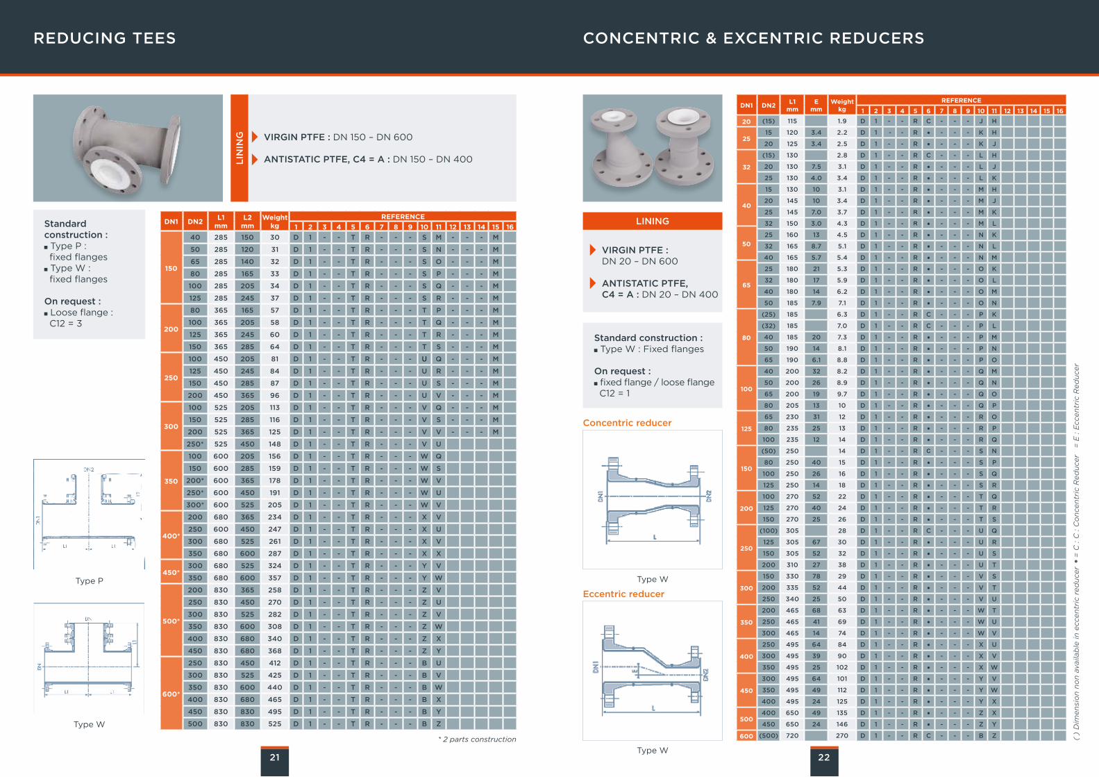
REDUCING TEES
VIRGIN PTFE : DN 150 – DN 600
ANTISTATIC PTFE, C4 = A : DN 150 – DN 400LIN
ING
CONCENTRIC & EXCENTRIC REDUCERS
22Type W
Type W
Type W
Type P
Standard construction : Type W : Fixed flanges
On request : fixed flange / loose flange C12 = 1
Standard construction : Type P :fixed flanges Type W :fixed flanges
On request : Loose flange : C12 = 3
DN1 DN2L1
mmL2
mmWeight
kgREFERENCE
1 2 3 4 5 6 7 8 9 10 11 12 13 14 15 16
150
40 285 150 30 D 1 - - T R - - - S M - - - M
50 285 120 31 D 1 - - T R - - - S N - - - M
65 285 140 32 D 1 - - T R - - - S O - - - M
80 285 165 33 D 1 - - T R - - - S P - - - M
100 285 205 34 D 1 - - T R - - - S Q - - - M
125 285 245 37 D 1 - - T R - - - S R - - - M
200
80 365 165 57 D 1 - - T R - - - T P - - - M
100 365 205 58 D 1 - - T R - - - T Q - - - M
125 365 245 60 D 1 - - T R - - - T R - - - M
150 365 285 64 D 1 - - T R - - - T S - - - M
250
100 450 205 81 D 1 - - T R - - - U Q - - - M
125 450 245 84 D 1 - - T R - - - U R - - - M
150 450 285 87 D 1 - - T R - - - U S - - - M
200 450 365 96 D 1 - - T R - - - U V - - - M
300
100 525 205 113 D 1 - - T R - - - V Q - - - M
150 525 285 116 D 1 - - T R - - - V S - - - M
200 525 365 125 D 1 - - T R - - - V V - - - M
250* 525 450 148 D 1 - - T R - - - V U
350
100 600 205 156 D 1 - - T R - - - W Q
150 600 285 159 D 1 - - T R - - - W S
200* 600 365 178 D 1 - - T R - - - W V
250* 600 450 191 D 1 - - T R - - - W U
300* 600 525 205 D 1 - - T R - - - W V
400*
200 680 365 234 D 1 - - T R - - - X V
250 600 450 247 D 1 - - T R - - - X U
300 680 525 261 D 1 - - T R - - - X V
350 680 600 287 D 1 - - T R - - - X X
450*300 680 525 324 D 1 - - T R - - - Y V
350 680 600 357 D 1 - - T R - - - Y W
500*
200 830 365 258 D 1 - - T R - - - Z V
250 830 450 270 D 1 - - T R - - - Z U
300 830 525 282 D 1 - - T R - - - Z V
350 830 600 308 D 1 - - T R - - - Z W
400 830 680 340 D 1 - - T R - - - Z X
450 830 680 368 D 1 - - T R - - - Z Y
600*
250 830 450 412 D 1 - - T R - - - B U
300 830 525 425 D 1 - - T R - - - B V
350 830 600 440 D 1 - - T R - - - B W
400 830 680 465 D 1 - - T R - - - B X
450 830 830 495 D 1 - - T R - - - B Y
500 830 830 525 D 1 - - T R - - - B Z
DN1 DN2L1
mmE
mmWeight
kg
REFERENCE
1 2 3 4 5 6 7 8 9 10 11 12 13 14 15 16
20 (15) 115 1.9 D 1 - - R C - - - J H
2515 120 3.4 2.2 D 1 - - R ● - - - K H
20 125 3.4 2.5 D 1 - - R ● - - - K J
32
(15) 130 2.8 D 1 - - R C - - - L H
20 130 7.5 3.1 D 1 - - R ● - - - L J
25 130 4.0 3.4 D 1 - - R ● - - - L K
40
15 130 10 3.1 D 1 - - R ● - - - M H
20 145 10 3.4 D 1 - - R ● - - - M J
25 145 7.0 3.7 D 1 - - R ● - - - M K
32 150 3.0 4.3 D 1 - - R ● - - - M L
50
25 160 13 4.5 D 1 - - R ● - - - N K
32 165 8.7 5.1 D 1 - - R ● - - - N L
40 165 5.7 5.4 D 1 - - R ● - - - N M
65
25 180 21 5.3 D 1 - - R ● - - - O K
32 180 17 5.9 D 1 - - R ● - - - O L
40 180 14 6.2 D 1 - - R ● - - - O M
50 185 7.9 7.1 D 1 - - R ● - - - O N
80
(25) 185 6.3 D 1 - - R C - - - P K
(32) 185 7.0 D 1 - - R C - - - P L
40 185 20 7.3 D 1 - - R ● - - - P M
50 190 14 8.1 D 1 - - R ● - - - P N
65 190 6.1 8.8 D 1 - - R ● - - - P O
100
40 200 32 8.2 D 1 - - R ● - - - Q M
50 200 26 8.9 D 1 - - R ● - - - Q N
65 200 19 9.7 D 1 - - R ● - - - Q O
80 205 13 10 D 1 - - R ● - - - Q P
125
65 230 31 12 D 1 - - R ● - - - R O
80 235 25 13 D 1 - - R ● - - - R P
100 235 12 14 D 1 - - R ● - - - R Q
150
(50) 250 14 D 1 - - R C - - - S N
80 250 40 15 D 1 - - R ● - - - S P
100 250 26 16 D 1 - - R ● - - - S Q
125 250 14 18 D 1 - - R ● - - - S R
200
100 270 52 22 D 1 - - R ● - - - T Q
125 270 40 24 D 1 - - R ● - - - T R
150 270 25 26 D 1 - - R ● - - - T S
250
(100) 305 28 D 1 - - R C - - - U Q
125 305 67 30 D 1 - - R ● - - - U R
150 305 52 32 D 1 - - R ● - - - U S
200 310 27 38 D 1 - - R ● - - - U T
300
150 330 78 29 D 1 - - R ● - - - V S
200 335 52 44 D 1 - - R ● - - - V T
250 340 25 50 D 1 - - R ● - - - V U
350
200 465 68 63 D 1 - - R ● - - - W T
250 465 41 69 D 1 - - R ● - - - W U
300 465 14 74 D 1 - - R ● - - - W V
400
250 495 64 84 D 1 - - R ● - - - X U
300 495 39 90 D 1 - - R ● - - - X V
350 495 25 102 D 1 - - R ● - - - X W
450
300 495 64 101 D 1 - - R ● - - - Y V
350 495 49 112 D 1 - - R ● - - - Y W
400 495 24 125 D 1 - - R ● - - - Y X
500400 650 49 135 D 1 - - R ● - - - Z X
450 650 24 146 D 1 - - R ● - - - Z Y
600 (500) 720 270 D 1 - - R C - - - B Z* 2 parts construction
VIRGIN PTFE : DN 20 – DN 600
ANTISTATIC PTFE, C4 = A : DN 20 – DN 400
LINING
Eccentric reducer
Concentric reducer
( )
Dim
en
sio
n n
on
ava
ilab
le in
ecc
en
tric
red
uce
r ●
= C
: C
: C
on
cen
tric
Red
uce
r =
E : E
ccen
tric
Red
uce
r
23
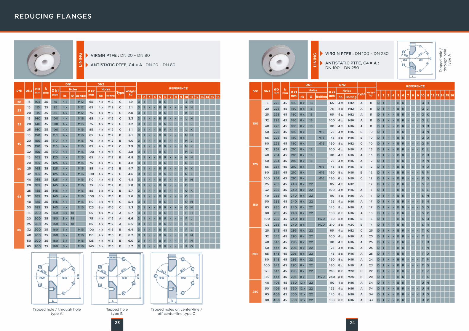
REDUCING FLANGES
Tapped hole / through holetype A
Tapped holetype B
Tapped holes on center-line /off center-line type C
24
VIRGIN PTFE : DN 20 – DN 80
ANTISTATIC PTFE, C4 = A : DN 20 – DN 80LIN
ING VIRGIN PTFE : DN 100 – DN 250
ANTISTATIC PTFE, C4 = A :DN 100 – DN 250L
ININ
G
DN1 DN2ØDmm
bmm
DN1 DN2REFERENCEØ k1
mmHoles
Ø k2mm
HolesType Weight
kgks Ø Bolting nb Bolting 1 2 3 4 5 6 7 8 9 10 11 12 13 14 15 16
20 15 105 35 75 4 x M12 65 4 x M12 C 1.9 D 1 - - B R - - - J H
2515 115 35 85 4 x M12 65 4 x M12 C 2.1 D 1 - - B R - - - K H
20 115 35 85 4 x M12 75 4 x M12 C 2.0 D 1 - - B R - - - K J
32
15 140 35 100 4 x M16 65 4 x M12 C 3.3 D 1 - - B R - - - L H
20 140 35 100 4 x M16 75 4 x M12 C 3.2 D 1 - - B R - - - L J
25 140 35 100 4 x M16 85 4 x M12 C 3.1 D 1 - - B R - - - L K
40
15 150 35 110 4 x M16 65 4 x M12 B 4.1 D 1 - - B R - - - M H
20 150 35 110 4 x M16 75 4 x M12 B 4.0 D 1 - - B R - - - M J
25 150 35 110 4 x M16 85 4 x M12 C 3.9 D 1 - - B R - - - M K
32 150 35 110 4 x M16 100 4 x M16 C 3.8 D 1 - - B R - - - M L
50
15 165 35 125 4 x M16 65 4 x M12 B 4.8 D 1 - - B R - - - N H
20 165 35 125 4 x M16 75 4 x M12 B 4.8 D 1 - - B R - - - N J
25 165 35 125 4 x M16 85 4 x M12 B 4.7 D 1 - - B R - - - N K
32 165 35 125 4 x M16 100 4 x M12 C 4.6 D 1 - - B R - - - N L
40 165 35 125 4 x M16 110 4 x M16 C 4.5 D 1 - - B R - - - N M
65
20 185 35 145 4 x M16 75 8 x M12 B 5.8 D 1 - - B R - - - O J
25 185 35 145 4 x M16 85 8 x M12 B 5.7 D 1 - - B R - - - O K
32 185 35 145 4 x M16 100 8 x M16 B 5.6 D 1 - - B R - - - O L
40 185 35 145 4 x M16 110 8 x M16 C 5.4 D 1 - - B R - - - O M
50 185 35 145 4 x M16 125 8 x M16 C 5.3 D 1 - - B R - - - O N
80
15 200 35 160 8 x 18 65 4 x M12 A 6.7 D 1 - - B R - - - P H
20 200 35 160 8 x 18 75 4 x M12 A 6.6 D 1 - - B R - - - P J
25 200 35 160 8 x 18 85 4 x M12 A 6.5 D 1 - - B R - - - P K
32 200 35 160 8 x M16 100 4 x M16 B 6.4 D 1 - - B R - - - P L
40 200 35 160 8 x M16 110 4 x M16 B 6.2 D 1 - - B R - - - P M
50 200 35 160 8 x M16 125 4 x M16 B 6.0 D 1 - - B R - - - P N
65 200 35 160 8 x M16 145 8 x M16 B 5.7 D 1 - - B R - - - P O
DN1 DN2ØDmm
bmm
DN1 DN2 REFERENCE
Ø k1mm
HolesØ k2mm
HolesType
Weightkg 1 2 3 4 5 6 7 8 9 10 11 12 13 14 15 16nb Ø Bolting nb Bolting
100
15 228 45 180 8 x 18 65 4 x M12 A 11 D 1 - - B R - - - Q H
20 228 45 180 8 x 18 75 4 x M12 A 11 D 1 - - B R - - - Q J
25 228 45 180 8 x 18 85 4 x M12 A 11 D 1 - - B R - - - Q K
32 228 45 180 8 x 18 100 4 x M16 A 11 D 1 - - B R - - - Q L
40 228 45 180 8 x 18 110 4 x M16 A 11 D 1 - - B R - - - Q M
50 228 45 180 8 x M16 125 4 x M16 B 10 D 1 - - B R - - - Q N
65 228 45 180 8 x M16 145 8 x M16 B 10 D 1 - - B R - - - Q O
80 228 45 180 8 x M16 160 8 x M12 C 10 D 1 - - B R - - - Q P
125
32 254 45 210 8 x 18 100 4 x M16 A 13 D 1 - - B R - - - R L
40 254 45 210 8 x 18 110 4 x M16 A 13 D 1 - - B R - - - R M
50 254 45 210 8 x 18 125 4 x M16 A 12 D 1 - - B R - - - R N
65 254 45 210 8 x M16 145 8 x M16 B 12 D 1 - - B R - - - R O
80 254 45 210 8 x M16 160 8 x M16 B 12 D 1 - - B R - - - R P
100 254 45 210 8 x M16 180 8 x M16 C 12 D 1 - - B R - - - R Q
150
25 285 45 240 8 x 22 85 4 x M12 17 D 1 - - B R - - - S K
32 285 45 240 8 x 22 100 4 x M16 A 17 D 1 - - B R - - - S L
40 285 45 240 8 x 22 110 4 x M16 A 17 D 1 - - B R - - - S M
50 285 45 240 8 x 22 125 4 x M16 A 17 D 1 - - B R - - - S N
65 285 45 240 8 x 22 145 8 x M16 A 17 D 1 - - B R - - - S O
80 285 45 240 8 x 22 160 8 x M16 A 16 D 1 - - B R - - - S P
100 285 45 240 8 x M20 180 8 x M16 B 15 D 1 - - B R - - - S Q
125 285 45 240 8 x M20 210 8 x M20 B 14 D 1 - - B R - - - S R
200
25 343 45 295 8 x 22 85 4 x M12 C 25 D 1 - - B R - - - T K
32 343 45 295 8 x 22 100 4 x M16 A 25 D 1 - - B R - - - T L
40 343 45 295 8 x 22 110 4 x M16 A 25 D 1 - - B R - - - T M
50 343 45 295 8 x 22 125 4 x M16 A 25 D 1 - - B R - - - T N
65 343 45 295 8 x 22 145 8 x M16 A 25 D 1 - - B R - - - T O
80 343 45 295 8 x 22 160 8 x M16 A 24 D 1 - - B R - - - T P
100 343 45 295 8 x 22 180 8 x M16 A 23 D 1 - - B R - - - T Q
125 343 45 295 8 x 22 210 8 x M20 B 22 D 1 - - B R - - - T R
150 343 45 295 8 x M20 240 8 x M20 B 20 D 1 - - B R - - - T S
250
40 406 45 350 12 x 22 110 4 x M16 A 34 D 1 - - B R - - - U M
50 406 45 350 12 x 22 125 4 x M16 A 34 D 1 - - B R - - - U N
65 406 45 350 12 x 22 145 8 x M16 A 34 D 1 - - B R - - - U O
80 406 45 350 12 x 22 160 8 x M16 A 33 D 1 - - B R - - - U P
Tap
ped
ho
le /
th
rou
gh
ho
leTyp
e A
25
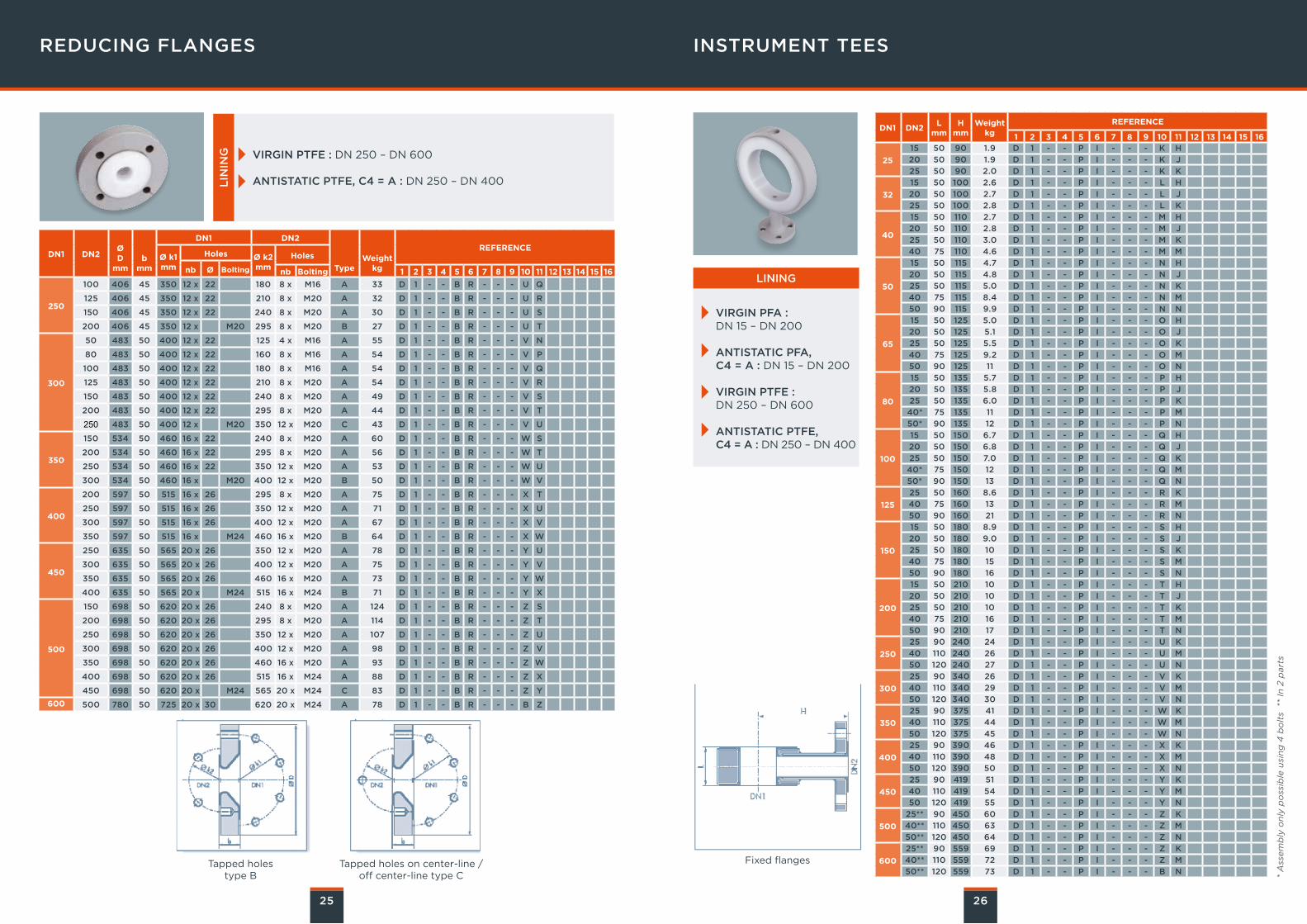
REDUCING FLANGES INSTRUMENT TEES
VIRGIN PTFE : DN 250 – DN 600
ANTISTATIC PTFE, C4 = A : DN 250 – DN 400LIN
ING
26
Tapped holestype B
Tapped holes on center-line /off center-line type C
DN1 DN2ØD
mmb
mm
DN1 DN2
TypeWeight
kg
REFERENCEØ k1mm
Holes Ø k2mm
Holes
nb Ø Bolting nb Bolting 1 2 3 4 5 6 7 8 9 10 11 12 13 14 15 16
250
100 406 45 350 12 x 22 180 8 x M16 A 33 D 1 - - B R - - - U Q
125 406 45 350 12 x 22 210 8 x M20 A 32 D 1 - - B R - - - U R
150 406 45 350 12 x 22 240 8 x M20 A 30 D 1 - - B R - - - U S
200 406 45 350 12 x M20 295 8 x M20 B 27 D 1 - - B R - - - U T
300
50 483 50 400 12 x 22 125 4 x M16 A 55 D 1 - - B R - - - V N
80 483 50 400 12 x 22 160 8 x M16 A 54 D 1 - - B R - - - V P
100 483 50 400 12 x 22 180 8 x M16 A 54 D 1 - - B R - - - V Q
125 483 50 400 12 x 22 210 8 x M20 A 54 D 1 - - B R - - - V R
150 483 50 400 12 x 22 240 8 x M20 A 49 D 1 - - B R - - - V S
200 483 50 400 12 x 22 295 8 x M20 A 44 D 1 - - B R - - - V T
250 483 50 400 12 x M20 350 12 x M20 C 43 D 1 - - B R - - - V U
350
150 534 50 460 16 x 22 240 8 x M20 A 60 D 1 - - B R - - - W S
200 534 50 460 16 x 22 295 8 x M20 A 56 D 1 - - B R - - - W T
250 534 50 460 16 x 22 350 12 x M20 A 53 D 1 - - B R - - - W U
300 534 50 460 16 x M20 400 12 x M20 B 50 D 1 - - B R - - - W V
400
200 597 50 515 16 x 26 295 8 x M20 A 75 D 1 - - B R - - - X T
250 597 50 515 16 x 26 350 12 x M20 A 71 D 1 - - B R - - - X U
300 597 50 515 16 x 26 400 12 x M20 A 67 D 1 - - B R - - - X V
350 597 50 515 16 x M24 460 16 x M20 B 64 D 1 - - B R - - - X W
450
250 635 50 565 20 x 26 350 12 x M20 A 78 D 1 - - B R - - - Y U
300 635 50 565 20 x 26 400 12 x M20 A 75 D 1 - - B R - - - Y V
350 635 50 565 20 x 26 460 16 x M20 A 73 D 1 - - B R - - - Y W
400 635 50 565 20 x M24 515 16 x M24 B 71 D 1 - - B R - - - Y X
500
150 698 50 620 20 x 26 240 8 x M20 A 124 D 1 - - B R - - - Z S
200 698 50 620 20 x 26 295 8 x M20 A 114 D 1 - - B R - - - Z T
250 698 50 620 20 x 26 350 12 x M20 A 107 D 1 - - B R - - - Z U
300 698 50 620 20 x 26 400 12 x M20 A 98 D 1 - - B R - - - Z V
350 698 50 620 20 x 26 460 16 x M20 A 93 D 1 - - B R - - - Z W
400 698 50 620 20 x 26 515 16 x M24 A 88 D 1 - - B R - - - Z X
450 698 50 620 20 x M24 565 20 x M24 C 83 D 1 - - B R - - - Z Y
600 500 780 50 725 20 x 30 620 20 x M24 A 78 D 1 - - B R - - - B Z
DN1 DN2L
mmH
mmWeight
kgREFERENCE
1 2 3 4 5 6 7 8 9 10 11 12 13 14 15 16
25
15 50 90 1.9 D 1 - - P I - - - K H
20 50 90 1.9 D 1 - - P I - - - K J
25 50 90 2.0 D 1 - - P I - - - K K
32
15 50 100 2.6 D 1 - - P I - - - L H
20 50 100 2.7 D 1 - - P I - - - L J
25 50 100 2.8 D 1 - - P I - - - L K
40
15 50 110 2.7 D 1 - - P I - - - M H
20 50 110 2.8 D 1 - - P I - - - M J
25 50 110 3.0 D 1 - - P I - - - M K
40 75 110 4.6 D 1 - - P I - - - M M
50
15 50 115 4.7 D 1 - - P I - - - N H
20 50 115 4.8 D 1 - - P I - - - N J
25 50 115 5.0 D 1 - - P I - - - N K
40 75 115 8.4 D 1 - - P I - - - N M
50 90 115 9.9 D 1 - - P I - - - N N
65
15 50 125 5.0 D 1 - - P I - - - O H
20 50 125 5.1 D 1 - - P I - - - O J
25 50 125 5.5 D 1 - - P I - - - O K
40 75 125 9.2 D 1 - - P I - - - O M
50 90 125 11 D 1 - - P I - - - O N
80
15 50 135 5.7 D 1 - - P I - - - P H
20 50 135 5.8 D 1 - - P I - - - P J
25 50 135 6.0 D 1 - - P I - - - P K
40* 75 135 11 D 1 - - P I - - - P M
50* 90 135 12 D 1 - - P I - - - P N
100
15 50 150 6.7 D 1 - - P I - - - Q H
20 50 150 6.8 D 1 - - P I - - - Q J
25 50 150 7.0 D 1 - - P I - - - Q K
40* 75 150 12 D 1 - - P I - - - Q M
50* 90 150 13 D 1 - - P I - - - Q N
125
25 50 160 8.6 D 1 - - P I - - - R K
40 75 160 13 D 1 - - P I - - - R M
50 90 160 21 D 1 - - P I - - - R N
150
15 50 180 8.9 D 1 - - P I - - - S H
20 50 180 9.0 D 1 - - P I - - - S J
25 50 180 10 D 1 - - P I - - - S K
40 75 180 15 D 1 - - P I - - - S M
50 90 180 16 D 1 - - P I - - - S N
200
15 50 210 10 D 1 - - P I - - - T H
20 50 210 10 D 1 - - P I - - - T J
25 50 210 10 D 1 - - P I - - - T K
40 75 210 16 D 1 - - P I - - - T M
50 90 210 17 D 1 - - P I - - - T N
250
25 90 240 24 D 1 - - P I - - - U K
40 110 240 26 D 1 - - P I - - - U M
50 120 240 27 D 1 - - P I - - - U N
300
25 90 340 26 D 1 - - P I - - - V K
40 110 340 29 D 1 - - P I - - - V M
50 120 340 30 D 1 - - P I - - - V N
350
25 90 375 41 D 1 - - P I - - - W K
40 110 375 44 D 1 - - P I - - - W M
50 120 375 45 D 1 - - P I - - - W N
400
25 90 390 46 D 1 - - P I - - - X K
40 110 390 48 D 1 - - P I - - - X M
50 120 390 50 D 1 - - P I - - - X N
450
25 90 419 51 D 1 - - P I - - - Y K
40 110 419 54 D 1 - - P I - - - Y M
50 120 419 55 D 1 - - P I - - - Y N
500
25** 90 450 60 D 1 - - P I - - - Z K
40** 110 450 63 D 1 - - P I - - - Z M
50** 120 450 64 D 1 - - P I - - - Z N
600
25** 90 559 69 D 1 - - P I - - - Z K
40** 110 559 72 D 1 - - P I - - - Z M
50** 120 559 73 D 1 - - P I - - - B N
VIRGIN PFA : DN 15 – DN 200
ANTISTATIC PFA, C4 = A : DN 15 – DN 200
VIRGIN PTFE :DN 250 – DN 600
ANTISTATIC PTFE, C4 = A : DN 250 – DN 400
LINING
Fixed flanges
* A
ssem
bly
on
ly p
oss
ible
usi
ng
4 b
olt
s *
* In
2 p
art
s
27
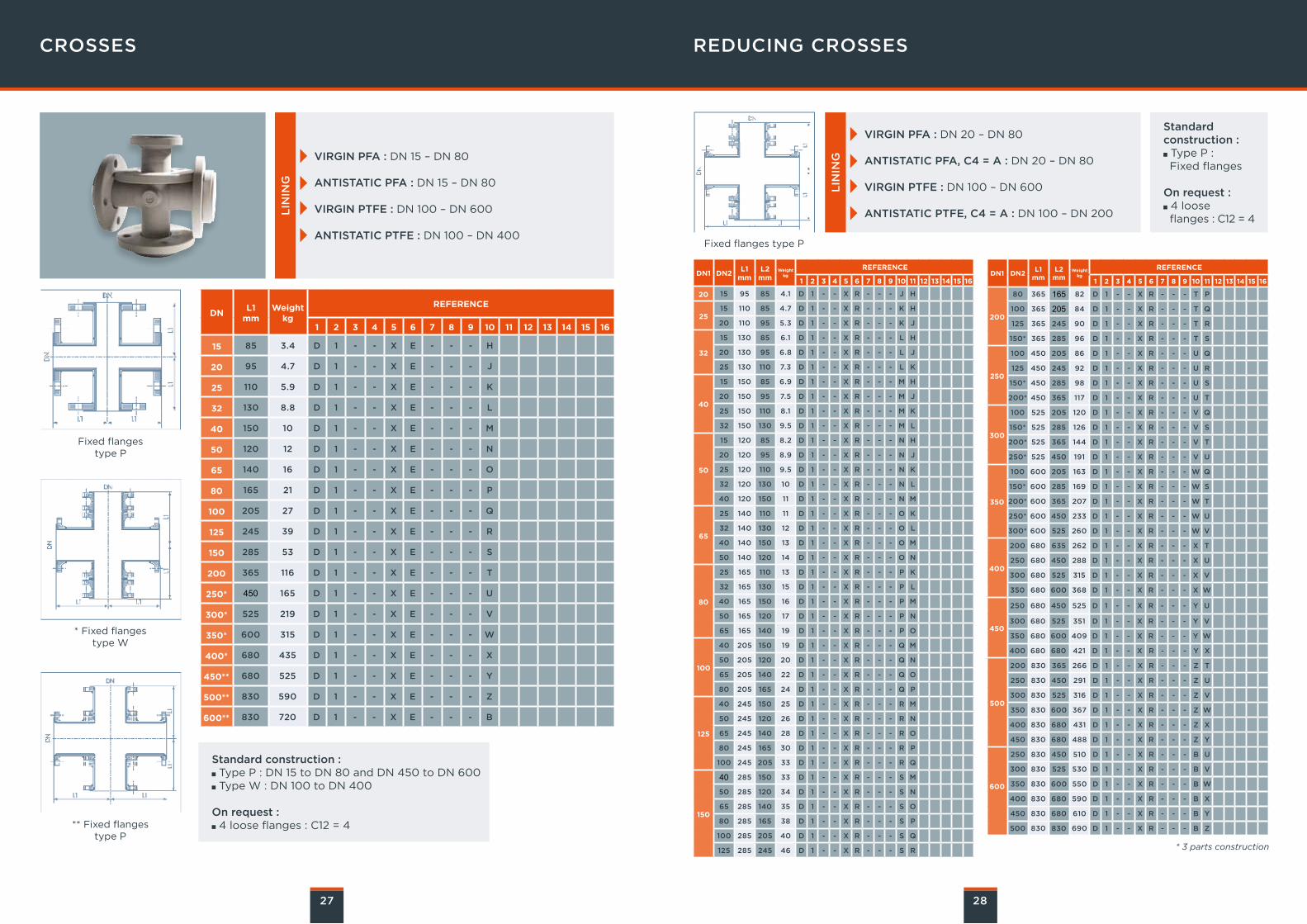
CROSSES
VIRGIN PFA : DN 15 – DN 80
ANTISTATIC PFA : DN 15 – DN 80
VIRGIN PTFE : DN 100 – DN 600
ANTISTATIC PTFE : DN 100 – DN 400
LIN
ING
** Fixed flangestype P
* Fixed flangestype W
Fixed flangestype P
Standard construction : Type P : DN 15 to DN 80 and DN 450 to DN 600 Type W : DN 100 to DN 400
On request : 4 loose flanges : C12 = 4
REDUCING CROSSES
28
VIRGIN PFA : DN 20 – DN 80
ANTISTATIC PFA, C4 = A : DN 20 – DN 80
VIRGIN PTFE : DN 100 – DN 600
ANTISTATIC PTFE, C4 = A : DN 100 – DN 200
LIN
ING
DNL1
mmWeight
kg
REFERENCE
1 2 3 4 5 6 7 8 9 10 11 12 13 14 15 16
15 85 3.4 D 1 - - X E - - - H
20 95 4.7 D 1 - - X E - - - J
25 110 5.9 D 1 - - X E - - - K
32 130 8.8 D 1 - - X E - - - L
40 150 10 D 1 - - X E - - - M
50 120 12 D 1 - - X E - - - N
65 140 16 D 1 - - X E - - - O
80 165 21 D 1 - - X E - - - P
100 205 27 D 1 - - X E - - - Q
125 245 39 D 1 - - X E - - - R
150 285 53 D 1 - - X E - - - S
200 365 116 D 1 - - X E - - - T
250* 450 165 D 1 - - X E - - - U
300* 525 219 D 1 - - X E - - - V
350* 600 315 D 1 - - X E - - - W
400* 680 435 D 1 - - X E - - - X
450** 680 525 D 1 - - X E - - - Y
500** 830 590 D 1 - - X E - - - Z
600** 830 720 D 1 - - X E - - - B
Fixed flanges type P
Standard construction : Type P : Fixed flanges
On request : 4 looseflanges : C12 = 4
DN1 DN2L1
mmL2
mmWeight
kg
REFERENCE
1 2 3 4 5 6 7 8 9 10 11 12 13 14 15 16
20 15 95 85 4.1 D 1 - - X R - - - J H
2515 110 85 4.7 D 1 - - X R - - - K H
20 110 95 5.3 D 1 - - X R - - - K J
32
15 130 85 6.1 D 1 - - X R - - - L H
20 130 95 6.8 D 1 - - X R - - - L J
25 130 110 7.3 D 1 - - X R - - - L K
40
15 150 85 6.9 D 1 - - X R - - - M H
20 150 95 7.5 D 1 - - X R - - - M J
25 150 110 8.1 D 1 - - X R - - - M K
32 150 130 9.5 D 1 - - X R - - - M L
50
15 120 85 8.2 D 1 - - X R - - - N H
20 120 95 8.9 D 1 - - X R - - - N J
25 120 110 9.5 D 1 - - X R - - - N K
32 120 130 10 D 1 - - X R - - - N L
40 120 150 11 D 1 - - X R - - - N M
65
25 140 110 11 D 1 - - X R - - - O K
32 140 130 12 D 1 - - X R - - - O L
40 140 150 13 D 1 - - X R - - - O M
50 140 120 14 D 1 - - X R - - - O N
80
25 165 110 13 D 1 - - X R - - - P K
32 165 130 15 D 1 - - X R - - - P L
40 165 150 16 D 1 - - X R - - - P M
50 165 120 17 D 1 - - X R - - - P N
65 165 140 19 D 1 - - X R - - - P O
100
40 205 150 19 D 1 - - X R - - - Q M
50 205 120 20 D 1 - - X R - - - Q N
65 205 140 22 D 1 - - X R - - - Q O
80 205 165 24 D 1 - - X R - - - Q P
125
40 245 150 25 D 1 - - X R - - - R M
50 245 120 26 D 1 - - X R - - - R N
65 245 140 28 D 1 - - X R - - - R O
80 245 165 30 D 1 - - X R - - - R P
100 245 205 33 D 1 - - X R - - - R Q
150
40 285 150 33 D 1 - - X R - - - S M
50 285 120 34 D 1 - - X R - - - S N
65 285 140 35 D 1 - - X R - - - S O
80 285 165 38 D 1 - - X R - - - S P
100 285 205 40 D 1 - - X R - - - S Q
125 285 245 46 D 1 - - X R - - - S R
DN1 DN2L1
mmL2
mmWeight
kg
REFERENCE
1 2 3 4 5 6 7 8 9 10 11 12 13 14 15 16
200
80 365 165 82 D 1 - - X R - - - T P
100 365 205 84 D 1 - - X R - - - T Q
125 365 245 90 D 1 - - X R - - - T R
150* 365 285 96 D 1 - - X R - - - T S
250
100 450 205 86 D 1 - - X R - - - U Q
125 450 245 92 D 1 - - X R - - - U R
150* 450 285 98 D 1 - - X R - - - U S
200* 450 365 117 D 1 - - X R - - - U T
300
100 525 205 120 D 1 - - X R - - - V Q
150* 525 285 126 D 1 - - X R - - - V S
200* 525 365 144 D 1 - - X R - - - V T
250* 525 450 191 D 1 - - X R - - - V U
350
100 600 205 163 D 1 - - X R - - - W Q
150* 600 285 169 D 1 - - X R - - - W S
200* 600 365 207 D 1 - - X R - - - W T
250* 600 450 233 D 1 - - X R - - - W U
300* 600 525 260 D 1 - - X R - - - W V
400
200 680 635 262 D 1 - - X R - - - X T
250 680 450 288 D 1 - - X R - - - X U
300 680 525 315 D 1 - - X R - - - X V
350 680 600 368 D 1 - - X R - - - X W
450
250 680 450 525 D 1 - - X R - - - Y U
300 680 525 351 D 1 - - X R - - - Y V
350 680 600 409 D 1 - - X R - - - Y W
400 680 680 421 D 1 - - X R - - - Y X
500
200 830 365 266 D 1 - - X R - - - Z T
250 830 450 291 D 1 - - X R - - - Z U
300 830 525 316 D 1 - - X R - - - Z V
350 830 600 367 D 1 - - X R - - - Z W
400 830 680 431 D 1 - - X R - - - Z X
450 830 680 488 D 1 - - X R - - - Z Y
600
250 830 450 510 D 1 - - X R - - - B U
300 830 525 530 D 1 - - X R - - - B V
350 830 600 550 D 1 - - X R - - - B W
400 830 680 590 D 1 - - X R - - - B X
450 830 680 610 D 1 - - X R - - - B Y
500 830 830 690 D 1 - - X R - - - B Z
* 3 parts construction
29
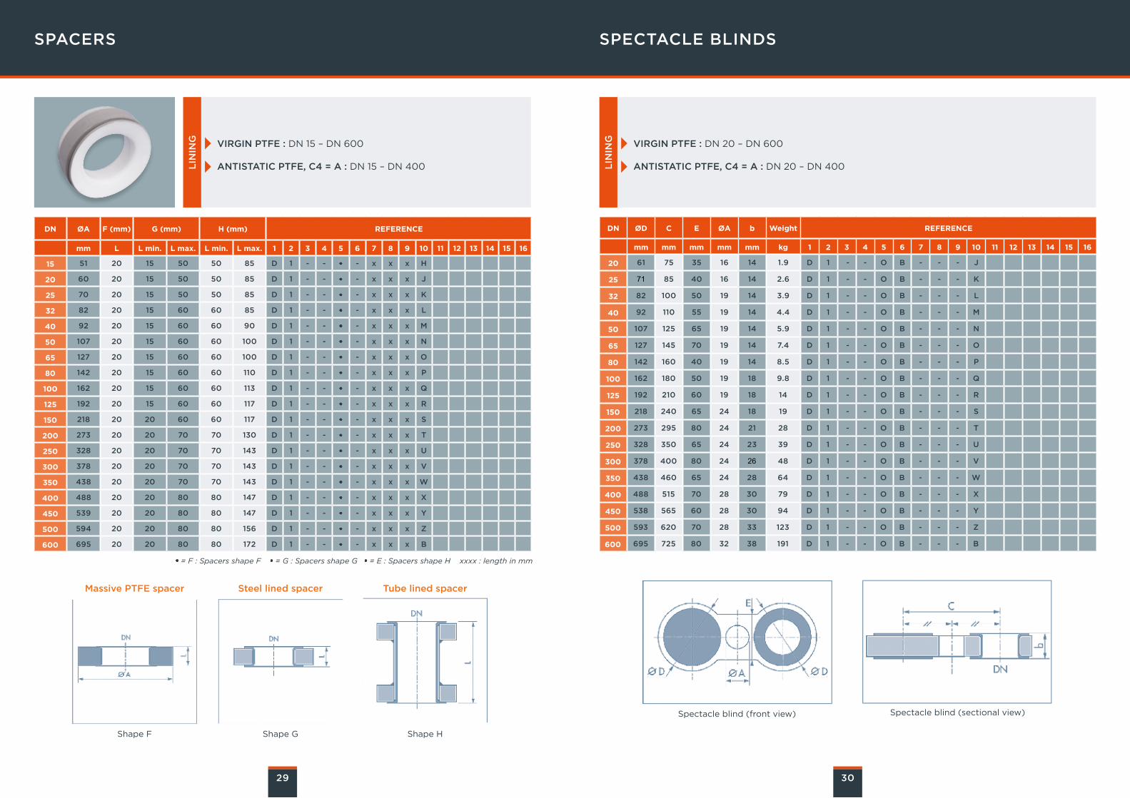
SPACERS
VIRGIN PTFE : DN 15 – DN 600
ANTISTATIC PTFE, C4 = A : DN 15 – DN 400
VIRGIN PTFE : DN 20 – DN 600
ANTISTATIC PTFE, C4 = A : DN 20 – DN 400LIN
ING
LIN
ING
= F : Spacers shape F = G : Spacers shape G = E : Spacers shape H xxxx : length in mm
Shape F
Massive PTFE spacer
Shape G
Spectacle blind (front view)
Steel lined spacer
Shape H
Tube lined spacer
SPECTACLE BLINDS
30
DN ØA F (mm) G (mm) H (mm) REFERENCE
mm L L min. L max. L min. L max. 1 2 3 4 5 6 7 8 9 10 11 12 13 14 15 16
15 51 20 15 50 50 85 D 1 - - - x x x H
20 60 20 15 50 50 85 D 1 - - - x x x J
25 70 20 15 50 50 85 D 1 - - - x x x K
32 82 20 15 60 60 85 D 1 - - - x x x L
40 92 20 15 60 60 90 D 1 - - - x x x M
50 107 20 15 60 60 100 D 1 - - - x x x N
65 127 20 15 60 60 100 D 1 - - - x x x O
80 142 20 15 60 60 110 D 1 - - - x x x P
100 162 20 15 60 60 113 D 1 - - - x x x Q
125 192 20 15 60 60 117 D 1 - - - x x x R
150 218 20 20 60 60 117 D 1 - - - x x x S
200 273 20 20 70 70 130 D 1 - - - x x x T
250 328 20 20 70 70 143 D 1 - - - x x x U
300 378 20 20 70 70 143 D 1 - - - x x x V
350 438 20 20 70 70 143 D 1 - - - x x x W
400 488 20 20 80 80 147 D 1 - - - x x x X
450 539 20 20 80 80 147 D 1 - - - x x x Y
500 594 20 20 80 80 156 D 1 - - - x x x Z
600 695 20 20 80 80 172 D 1 - - - x x x B
DN ØD C E ØA b Weight REFERENCE
mm mm mm mm mm kg 1 2 3 4 5 6 7 8 9 10 11 12 13 14 15 16
20 61 75 35 16 14 1.9 D 1 - - O B - - - J
25 71 85 40 16 14 2.6 D 1 - - O B - - - K
32 82 100 50 19 14 3.9 D 1 - - O B - - - L
40 92 110 55 19 14 4.4 D 1 - - O B - - - M
50 107 125 65 19 14 5.9 D 1 - - O B - - - N
65 127 145 70 19 14 7.4 D 1 - - O B - - - O
80 142 160 40 19 14 8.5 D 1 - - O B - - - P
100 162 180 50 19 18 9.8 D 1 - - O B - - - Q
125 192 210 60 19 18 14 D 1 - - O B - - - R
150 218 240 65 24 18 19 D 1 - - O B - - - S
200 273 295 80 24 21 28 D 1 - - O B - - - T
250 328 350 65 24 23 39 D 1 - - O B - - - U
300 378 400 80 24 26 48 D 1 - - O B - - - V
350 438 460 65 24 28 64 D 1 - - O B - - - W
400 488 515 70 28 30 79 D 1 - - O B - - - X
450 538 565 60 28 30 94 D 1 - - O B - - - Y
500 593 620 70 28 33 123 D 1 - - O B - - - Z
600 695 725 80 32 38 191 D 1 - - O B - - - B
Spectacle blind (sectional view)
31
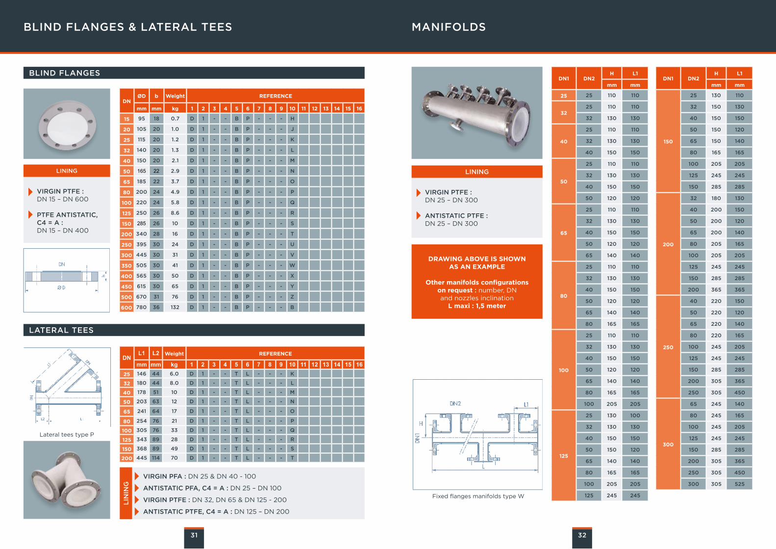
BLIND FLANGES & LATERAL TEES
Lateral tees type P
MANIFOLDS
32
Fixed flanges manifolds type W
DNØD b Weight REFERENCE
mm mm kg 1 2 3 4 5 6 7 8 9 10 11 12 13 14 15 16
15 95 18 0.7 D 1 - - B P - - - H
20 105 20 1.0 D 1 - - B P - - - J
25 115 20 1.2 D 1 - - B P - - - K
32 140 20 1.3 D 1 - - B P - - - L
40 150 20 2.1 D 1 - - B P - - - M
50 165 22 2.9 D 1 - - B P - - - N
65 185 22 3.7 D 1 - - B P - - - O
80 200 24 4.9 D 1 - - B P - - - P
100 220 24 5.8 D 1 - - B P - - - Q
125 250 26 8.6 D 1 - - B P - - - R
150 285 26 10 D 1 - - B P - - - S
200 340 28 16 D 1 - - B P - - - T
250 395 30 24 D 1 - - B P - - - U
300 445 30 31 D 1 - - B P - - - V
350 505 30 41 D 1 - - B P - - - W
400 565 30 50 D 1 - - B P - - - X
450 615 30 65 D 1 - - B P - - - Y
500 670 31 76 D 1 - - B P - - - Z
600 780 36 132 D 1 - - B P - - - B
VIRGIN PTFE : DN 15 – DN 600
PTFE ANTISTATIC, C4 = A :DN 15 – DN 400
LINING
DNL1 L2 Weight REFERENCE
mm mm kg 1 2 3 4 5 6 7 8 9 10 11 12 13 14 15 1625 146 44 6.0 D 1 - - T L - - - K
32 180 44 8.0 D 1 - - T L - - - L
40 178 51 10 D 1 - - T L - - - M
50 203 63 12 D 1 - - T L - - - N
65 241 64 17 D 1 - - T L - - - O
80 254 76 21 D 1 - - T L - - - P
100 305 76 33 D 1 - - T L - - - Q
125 343 89 28 D 1 - - T L - - - R
150 368 89 49 D 1 - - T L - - - S
200 445 114 70 D 1 - - T L - - - T
LATERAL TEES
BLIND FLANGES
VIRGIN PFA : DN 25 & DN 40 - 100
ANTISTATIC PFA, C4 = A : DN 25 – DN 100
VIRGIN PTFE : DN 32, DN 65 & DN 125 - 200
ANTISTATIC PTFE, C4 = A : DN 125 – DN 200
LIN
ING
DN1 DN2H L1
mm mm
25 25 110 110
3225 110 110
32 130 130
40
25 110 110
32 130 130
40 150 150
50
25 110 110
32 130 130
40 150 150
50 120 120
65
25 110 110
32 130 130
40 150 150
50 120 120
65 140 140
80
25 110 110
32 130 130
40 150 150
50 120 120
65 140 140
80 165 165
100
25 110 110
32 130 130
40 150 150
50 120 120
65 140 140
80 165 165
100 205 205
125
25 130 100
32 130 130
40 150 150
50 150 120
65 140 140
80 165 165
100 205 205
125 245 245
DN1 DN2H L1
mm mm
150
25 130 110
32 150 130
40 150 150
50 150 120
65 150 140
80 165 165
100 205 205
125 245 245
150 285 285
200
32 180 130
40 200 150
50 200 120
65 200 140
80 205 165
100 205 205
125 245 245
150 285 285
200 365 365
250
40 220 150
50 220 120
65 220 140
80 220 165
100 245 205
125 245 245
150 285 285
200 305 365
250 305 450
300
65 245 140
80 245 165
100 245 205
125 245 245
150 285 285
200 305 365
250 305 450
300 305 525
DRAWING ABOVE IS SHOWNAS AN EXAMPLE
Other manifolds configurations on request : number, DN and nozzles inclination
L maxi : 1,5 meter
VIRGIN PTFE : DN 25 – DN 300
ANTISTATIC PTFE : DN 25 – DN 300
LINING
33
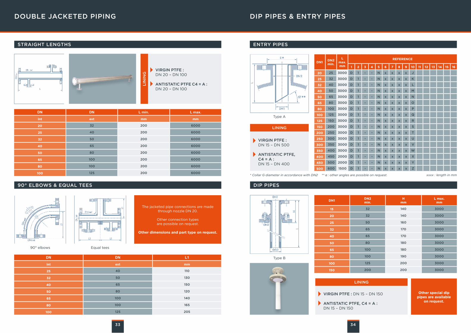
DOUBLE JACKETED PIPING
90° elbows Equal tees
VIRGIN PTFE : DN 20 – DN 100
ANTISTATIC PTFE C4 = A : DN 20 – DN 100
LIN
ING
DIP PIPES & ENTRY PIPES
34
The jacketed pipe connections are made through nozzle DN 20.
Other connection types are possible on request.
Other dimensions and part type on request.
Other special dip pipes are available
on request.
DN DN L min. L max.
int ext mm mm
20 32 200 6000
25 40 200 6000
32 50 200 6000
40 65 200 6000
50 80 200 6000
65 100 200 6000
80 100 200 6000
100 125 200 6000
DN DN L1
int ext mm
25 40 110
32 50 130
40 65 150
50 80 120
65 100 140
80 100 165
100 125 205
STRAIGHT LENGTHS ENTRY PIPES
90° ELBOWS & EQUAL TEES DIP PIPES
DN1DN2min.
L max.mm
REFERENCE
1 2 3 4 5 6 7 8 9 10 11 12 13 14 15 16
20 25 3000 D 1 - - N x x x x J
25 32 3000 D 1 - - N x x x x K
32 40 3000 D 1 - - N x x x x L
40 50 3000 D 1 - - N x x x x M
50 65 3000 D 1 - - N x x x x N
65 80 3000 D 1 - - N x x x x O
80 100 3000 D 1 - - N x x x x P
100 125 3000 D 1 - - N x x x x Q
125 150 3000 D 1 - - N x x x x R
150 200 3000 D 1 - - N x x x x S
200 250 3000 D 1 - - N x x x x T
250 300 3000 D 1 - - N x x x x U
300 350 3000 D 1 - - N x x x x V
350 400 3000 D 1 - - N x x x x W
400 450 2000 D 1 - - N x x x x X
450 500 2000 D 1 - - N x x x x Y
500 600 1500 D 1 - - N x x x x Z
DN1DN2 min.
Hmm
L max.mm
15 32 140 3000
20 32 140 3000
25 50 160 3000
32 65 170 3000
40 65 170 3000
50 80 180 3000
65 100 180 3000
80 100 190 3000
100 125 200 3000
150 200 200 3000
Type A
Type B
VIRGIN PTFE : DN 15 – DN 500
ANTISTATIC PTFE, C4 = A : DN 15 – DN 400
LINING
xxxx : length in mm* Collar G diameter in accordance with DN2 ** α : other angles are possible on request.
VIRGIN PTFE : DN 15 – DN 150
ANTISTATIC PTFE, C4 = A : DN 15 – DN 150
LINING

B2
2_
4_
E N
OV
EM
BE
R 2
016
| d
esig
n g
rap
hiq
ue
: A
GE
NC
E B
ER
LIO
Z
G LO B A L E X P E R T I N E L E C T R I C A L
P OW E R A N D A DVA N C E D M AT E R I A L S